US11070772B2 - Endoscope image-capturing device and endoscope device - Google Patents
Endoscope image-capturing device and endoscope device Download PDFInfo
- Publication number
- US11070772B2 US11070772B2 US15/198,351 US201615198351A US11070772B2 US 11070772 B2 US11070772 B2 US 11070772B2 US 201615198351 A US201615198351 A US 201615198351A US 11070772 B2 US11070772 B2 US 11070772B2
- Authority
- US
- United States
- Prior art keywords
- case
- electro
- image
- capturing device
- endoscope
- Prior art date
- Legal status (The legal status is an assumption and is not a legal conclusion. Google has not performed a legal analysis and makes no representation as to the accuracy of the status listed.)
- Active, expires
Links
- 238000006243 chemical reaction Methods 0.000 claims abstract description 71
- 238000007789 sealing Methods 0.000 claims abstract description 62
- 230000003287 optical effect Effects 0.000 claims abstract description 39
- 229920005989 resin Polymers 0.000 claims description 17
- 239000011347 resin Substances 0.000 claims description 17
- 238000012545 processing Methods 0.000 claims description 9
- 230000000903 blocking effect Effects 0.000 claims description 6
- 238000003780 insertion Methods 0.000 description 33
- 230000037431 insertion Effects 0.000 description 33
- 239000013307 optical fiber Substances 0.000 description 23
- 239000002131 composite material Substances 0.000 description 20
- 230000008878 coupling Effects 0.000 description 18
- 238000010168 coupling process Methods 0.000 description 18
- 238000005859 coupling reaction Methods 0.000 description 18
- 238000010586 diagram Methods 0.000 description 14
- 230000004048 modification Effects 0.000 description 12
- 238000012986 modification Methods 0.000 description 12
- 238000001029 thermal curing Methods 0.000 description 11
- 230000005540 biological transmission Effects 0.000 description 8
- 238000005476 soldering Methods 0.000 description 7
- 230000001954 sterilising effect Effects 0.000 description 7
- 238000004659 sterilization and disinfection Methods 0.000 description 7
- 238000004891 communication Methods 0.000 description 6
- 238000007654 immersion Methods 0.000 description 6
- 239000012212 insulator Substances 0.000 description 5
- 239000007788 liquid Substances 0.000 description 5
- 239000007769 metal material Substances 0.000 description 5
- 239000011521 glass Substances 0.000 description 4
- -1 polypropylene Polymers 0.000 description 4
- 239000011810 insulating material Substances 0.000 description 3
- 239000000463 material Substances 0.000 description 3
- 238000000034 method Methods 0.000 description 3
- 230000004044 response Effects 0.000 description 3
- YCKRFDGAMUMZLT-UHFFFAOYSA-N Fluorine atom Chemical compound [F] YCKRFDGAMUMZLT-UHFFFAOYSA-N 0.000 description 2
- 239000004696 Poly ether ether ketone Substances 0.000 description 2
- 239000004952 Polyamide Substances 0.000 description 2
- 239000004642 Polyimide Substances 0.000 description 2
- 239000004743 Polypropylene Substances 0.000 description 2
- 230000015556 catabolic process Effects 0.000 description 2
- 238000006731 degradation reaction Methods 0.000 description 2
- 230000000694 effects Effects 0.000 description 2
- 239000003822 epoxy resin Substances 0.000 description 2
- 239000011737 fluorine Substances 0.000 description 2
- 229910052731 fluorine Inorganic materials 0.000 description 2
- 230000006870 function Effects 0.000 description 2
- 238000003384 imaging method Methods 0.000 description 2
- 230000000149 penetrating effect Effects 0.000 description 2
- 229920002647 polyamide Polymers 0.000 description 2
- 229920001707 polybutylene terephthalate Polymers 0.000 description 2
- 229920000647 polyepoxide Polymers 0.000 description 2
- 229920002530 polyetherether ketone Polymers 0.000 description 2
- 229920001721 polyimide Polymers 0.000 description 2
- 229920001155 polypropylene Polymers 0.000 description 2
- 239000004810 polytetrafluoroethylene Substances 0.000 description 2
- 229920001343 polytetrafluoroethylene Polymers 0.000 description 2
- 229920002050 silicone resin Polymers 0.000 description 2
- 239000000758 substrate Substances 0.000 description 2
- 239000004677 Nylon Substances 0.000 description 1
- 229910001069 Ti alloy Inorganic materials 0.000 description 1
- RTAQQCXQSZGOHL-UHFFFAOYSA-N Titanium Chemical compound [Ti] RTAQQCXQSZGOHL-UHFFFAOYSA-N 0.000 description 1
- 230000004075 alteration Effects 0.000 description 1
- 230000004888 barrier function Effects 0.000 description 1
- 239000000919 ceramic Substances 0.000 description 1
- 230000000295 complement effect Effects 0.000 description 1
- 238000013461 design Methods 0.000 description 1
- 229920006351 engineering plastic Polymers 0.000 description 1
- RTZKZFJDLAIYFH-UHFFFAOYSA-N ether Substances CCOCC RTZKZFJDLAIYFH-UHFFFAOYSA-N 0.000 description 1
- 238000010438 heat treatment Methods 0.000 description 1
- 229910044991 metal oxide Inorganic materials 0.000 description 1
- 150000004706 metal oxides Chemical class 0.000 description 1
- 229920001778 nylon Polymers 0.000 description 1
- 230000002093 peripheral effect Effects 0.000 description 1
- 230000035699 permeability Effects 0.000 description 1
- 229920001643 poly(ether ketone) Polymers 0.000 description 1
- 229920002312 polyamide-imide Polymers 0.000 description 1
- 239000004417 polycarbonate Substances 0.000 description 1
- 229920000515 polycarbonate Polymers 0.000 description 1
- 239000005033 polyvinylidene chloride Substances 0.000 description 1
- 238000004382 potting Methods 0.000 description 1
- 230000008569 process Effects 0.000 description 1
- 230000009467 reduction Effects 0.000 description 1
- 230000003014 reinforcing effect Effects 0.000 description 1
- 239000004065 semiconductor Substances 0.000 description 1
- 230000008054 signal transmission Effects 0.000 description 1
- 229910001256 stainless steel alloy Inorganic materials 0.000 description 1
- 229910052719 titanium Inorganic materials 0.000 description 1
- 239000010936 titanium Substances 0.000 description 1
- 238000009834 vaporization Methods 0.000 description 1
- 230000008016 vaporization Effects 0.000 description 1
- 238000003466 welding Methods 0.000 description 1
Images


Classifications
-
- H—ELECTRICITY
- H04—ELECTRIC COMMUNICATION TECHNIQUE
- H04N—PICTORIAL COMMUNICATION, e.g. TELEVISION
- H04N7/00—Television systems
- H04N7/22—Adaptations for optical transmission
-
- A—HUMAN NECESSITIES
- A61—MEDICAL OR VETERINARY SCIENCE; HYGIENE
- A61B—DIAGNOSIS; SURGERY; IDENTIFICATION
- A61B1/00—Instruments for performing medical examinations of the interior of cavities or tubes of the body by visual or photographical inspection, e.g. endoscopes; Illuminating arrangements therefor
- A61B1/00002—Operational features of endoscopes
- A61B1/00011—Operational features of endoscopes characterised by signal transmission
- A61B1/00013—Operational features of endoscopes characterised by signal transmission using optical means
-
- A—HUMAN NECESSITIES
- A61—MEDICAL OR VETERINARY SCIENCE; HYGIENE
- A61B—DIAGNOSIS; SURGERY; IDENTIFICATION
- A61B1/00—Instruments for performing medical examinations of the interior of cavities or tubes of the body by visual or photographical inspection, e.g. endoscopes; Illuminating arrangements therefor
- A61B1/00064—Constructional details of the endoscope body
- A61B1/00071—Insertion part of the endoscope body
- A61B1/0008—Insertion part of the endoscope body characterised by distal tip features
-
- A—HUMAN NECESSITIES
- A61—MEDICAL OR VETERINARY SCIENCE; HYGIENE
- A61B—DIAGNOSIS; SURGERY; IDENTIFICATION
- A61B1/00—Instruments for performing medical examinations of the interior of cavities or tubes of the body by visual or photographical inspection, e.g. endoscopes; Illuminating arrangements therefor
- A61B1/00112—Connection or coupling means
-
- A—HUMAN NECESSITIES
- A61—MEDICAL OR VETERINARY SCIENCE; HYGIENE
- A61B—DIAGNOSIS; SURGERY; IDENTIFICATION
- A61B1/00—Instruments for performing medical examinations of the interior of cavities or tubes of the body by visual or photographical inspection, e.g. endoscopes; Illuminating arrangements therefor
- A61B1/04—Instruments for performing medical examinations of the interior of cavities or tubes of the body by visual or photographical inspection, e.g. endoscopes; Illuminating arrangements therefor combined with photographic or television appliances
- A61B1/045—Control thereof
-
- A—HUMAN NECESSITIES
- A61—MEDICAL OR VETERINARY SCIENCE; HYGIENE
- A61B—DIAGNOSIS; SURGERY; IDENTIFICATION
- A61B1/00—Instruments for performing medical examinations of the interior of cavities or tubes of the body by visual or photographical inspection, e.g. endoscopes; Illuminating arrangements therefor
- A61B1/04—Instruments for performing medical examinations of the interior of cavities or tubes of the body by visual or photographical inspection, e.g. endoscopes; Illuminating arrangements therefor combined with photographic or television appliances
- A61B1/05—Instruments for performing medical examinations of the interior of cavities or tubes of the body by visual or photographical inspection, e.g. endoscopes; Illuminating arrangements therefor combined with photographic or television appliances characterised by the image sensor, e.g. camera, being in the distal end portion
-
- A—HUMAN NECESSITIES
- A61—MEDICAL OR VETERINARY SCIENCE; HYGIENE
- A61B—DIAGNOSIS; SURGERY; IDENTIFICATION
- A61B1/00—Instruments for performing medical examinations of the interior of cavities or tubes of the body by visual or photographical inspection, e.g. endoscopes; Illuminating arrangements therefor
- A61B1/06—Instruments for performing medical examinations of the interior of cavities or tubes of the body by visual or photographical inspection, e.g. endoscopes; Illuminating arrangements therefor with illuminating arrangements
- A61B1/0661—Endoscope light sources
- A61B1/0669—Endoscope light sources at proximal end of an endoscope
-
- H—ELECTRICITY
- H04—ELECTRIC COMMUNICATION TECHNIQUE
- H04N—PICTORIAL COMMUNICATION, e.g. TELEVISION
- H04N23/00—Cameras or camera modules comprising electronic image sensors; Control thereof
- H04N23/50—Constructional details
- H04N23/51—Housings
-
- H04N5/2252—
-
- H—ELECTRICITY
- H04—ELECTRIC COMMUNICATION TECHNIQUE
- H04N—PICTORIAL COMMUNICATION, e.g. TELEVISION
- H04N7/00—Television systems
- H04N7/015—High-definition television systems
-
- A—HUMAN NECESSITIES
- A61—MEDICAL OR VETERINARY SCIENCE; HYGIENE
- A61B—DIAGNOSIS; SURGERY; IDENTIFICATION
- A61B1/00—Instruments for performing medical examinations of the interior of cavities or tubes of the body by visual or photographical inspection, e.g. endoscopes; Illuminating arrangements therefor
- A61B1/00002—Operational features of endoscopes
- A61B1/00043—Operational features of endoscopes provided with output arrangements
- A61B1/00045—Display arrangement
- A61B1/00048—Constructional features of the display
-
- H04N2005/2255—
-
- H—ELECTRICITY
- H04—ELECTRIC COMMUNICATION TECHNIQUE
- H04N—PICTORIAL COMMUNICATION, e.g. TELEVISION
- H04N23/00—Cameras or camera modules comprising electronic image sensors; Control thereof
- H04N23/50—Constructional details
- H04N23/555—Constructional details for picking-up images in sites, inaccessible due to their dimensions or hazardous conditions, e.g. endoscopes or borescopes
Definitions
- the present disclosure relates to an endoscope image-capturing device and an endoscope device.
- An endoscope device in the medical field captures an image of the inside of an observation target (living body) such as a human by using an image sensor so as to observe the inside of this living body (refer to Japanese Patent Application Laid-open No. 2012-245045 and Japanese Patent Application Laid-open No. 2005-66129, for example).
- the endoscope device (endoscope system) disclosed in Japanese Patent Application Laid-open No. 2012-245045 is a head-separated endoscope device including an insertion unit (endoscope scope) inserted into the living body, an endoscope image-capturing device (camera head) including an image sensor configured to capture an object image condensed by the insertion unit, a control device (image processor) configured to process an image signal output from the image sensor, and a cable electrically coupling between the image sensor and the control device.
- this image sensor is arranged in a sealed casing the inside of which is sealed (held watertightly and airtightly).
- a sealing connector such as a waterproof connector or a hermetic connector is attached to an opening of the sealed casing to transmit the image signal from the image sensor arranged inside the sealed casing to the outside of the sealed casing while maintaining the sealability (watertightness and airtightness) of the sealed casing.
- the image signal from the sealing connector is transmitted to a control device such as an image processor through a cable (refer to Japanese Patent Application Laid-open No. 2012-245045).
- an endoscope device disclosed in Japanese Patent Application Laid-open No. 2005-66129 is a head-separated endoscope device.
- the endoscope image-capturing device (camera head) disclosed in Japanese Patent Application Laid-open No. 2005-66129 is provided, inside this endoscope image-capturing device, with an electro-optic conversion element (E/O converter) configured to convert an image signal (electric signal) from the image sensor into an optical signal.
- the endoscope image-capturing device is configured to transmit the image signal from the image sensor as the optical signal to the control device through the cable. Transmission of the image signal as an optical signal is advantageous, in particular, for an increase in the data amount of the image signal for high image quality such as what is called 4K and 8K and a speeding up of signal transmission.
- the sealing connector disclosed in Japanese Patent Application Laid-open No. 2012-245045 includes a plurality of conductive pins penetrating between the inside and outside of the sealed casing. These conductive pins electrically couple the image sensor and the cable (control device). In other words, a typical sealing connector transmits an electric signal.
- the electro-optic conversion element includes a light source configured to emit light such as laser light. This light source is repeatedly turned on and off in optical communication, and thus typically has a lifetime shorter than that of the image sensor.
- a sealed structure sealed casing necessary for the image sensor needs to be temporarily unlocked to replace the electro-optic conversion element due to its failure and lifetime, and after the replacement, the sealability needs to be achieved again, which is reflected on the cost of the replacement.
- the electro-optic conversion element is provided outside the sealed casing.
- An image signal from the image sensor is transmitted as an electric signal to the outside of the sealed casing through the sealing connector.
- this image signal (electric signal) is converted into an optical signal by the electro-optic conversion element arranged outside the sealed casing.
- this optical signal is transmitted to the control device through the cable.
- the electro-optic conversion element is provided outside the sealed casing, making it difficult to protect the electro-optic conversion element against a medicinal solution used in sterilization involving wiping and liquid immersion and high-temperature and high-pressure vapor in autoclave processing.
- An endoscope image-capturing device includes: a first case inside of which is sealed; an image sensor arranged inside the first case; an electro-optic conversion element arranged outside the first case and configured to convert an image signal output from the image sensor into an optical signal; and a sealing member sealing the electro-optic conversion element.
- FIG. 1 illustrates a schematic configuration of an endoscope device according to an embodiment of the present disclosure
- FIG. 2 is a perspective diagram of a camera head illustrated in FIG. 1 when viewed from a base end side (side with which a composite cable is coupled);
- FIG. 3 is a perspective diagram of a sealed unit illustrated in FIG. 2 when viewed from a base end side (side with which an electro-optic combined module is coupled);
- FIG. 4 is a perspective diagram of a sealing connector illustrated in FIG. 3 when viewed from the inside of the sealed unit;
- FIG. 5 is a perspective diagram of the electro-optic combined module according to the embodiment of the present disclosure when viewed from a head side (side with which the sealed unit coupled);
- FIG. 6 is a perspective diagram of the internal structure of the electro-optic combined module illustrated in FIG. 5 when viewed from a base end side (side with which the composite cable coupled);
- FIG. 7 illustrates the internal structure of the electro-optic combined module illustrated in FIG. 5 when viewed from a side
- FIG. 8 is a perspective diagram of a receptacle illustrated in FIGS. 5 to 7 when viewed from a base end side (side with which first and second printed-circuit boards are coupled);
- FIG. 9 illustrates an array of a plurality of contacts illustrated in FIG. 8 ;
- FIG. 10 is a sectional view schematically illustrating an electro-optic conversion element mounted on a first printed-circuit board illustrated in FIGS. 6 and 7 ;
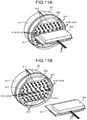
- FIG. 11A is a perspective diagram illustrating that the first printed-circuit board is attached to the receptacle illustrated in FIGS. 6 and 7 when viewed from a base end side of the receptacle;
- FIG. 11B is an exploded perspective view illustrating that the first printed-circuit board is removed from the receptacle illustrated in FIGS. 6 and 7 when viewed from the base end side of the receptacle;
- FIG. 12 illustrates a method of filling inside a second case illustrated in FIGS. 5 and 7 with a filling member
- FIG. 13 illustrates modification 1 of the embodiment of the present disclosure
- FIG. 14 illustrates the shapes of first conductive pins illustrated in FIG. 13 ;
- FIG. 15 illustrates modification 2 of the embodiment of the present disclosure.
- FIG. 1 illustrates a schematic configuration of an endoscope device 1 according to an embodiment of the present disclosure.
- the endoscope device 1 is used in the medical field to observe the inside of an observation target (living body) such as a human.
- the endoscope device 1 includes an insertion unit 2 , a light source device 3 , a light guide 4 , a camera head 5 , a composite cable 6 , a display device 7 , and a control device 8 .
- the insertion unit 2 is hard and elongated, and inserted into the living body.
- An optical system for condensing an object image is provided in the insertion unit 2 .
- the light source device 3 is coupled with one end of the light guide 4 to supply, through this one end of the light guide 4 , light for illuminating inside the living body.
- the light guide 4 has one end detachably coupled with the light source device 3 , and the other end detachably coupled with the insertion unit 2 .
- the light guide 4 transfers the light supplied from the light source device 3 from the one end to the other end so as to supply the light to the insertion unit 2 .
- the light supplied to the insertion unit 2 is emitted through a head of this insertion unit 2 to irradiate inside the living body. Then, the light (object image) emitted to the inside of the living body is condensed through the optical system in the insertion unit 2 .
- the camera head 5 has the functionality of an endoscope image-capturing device according to the present disclosure.
- the camera head 5 is detachably coupled with a base end of the insertion unit 2 .
- the camera head 5 captures the object image condensed through the insertion unit 2 and performs an electro-optic conversion on an image signal (electric signal) through this image capturing to obtain and output an optical signal.
- the configuration of the camera head 5 is described later in detail.
- the composite cable 6 includes a plurality of optical fibers 61 (refer to FIG. 6 ) and a plurality of electric signal cables 62 (refer to FIG. 6 ) under an outer cover 60 (refer to FIG. 6 ) as an outermost layer.
- the composite cable 6 has one end detachably coupled with the control device 8 and the other end coupled with the camera head 5 .
- the optical fibers 61 are arranged at a central position when viewed in a cross-section of the composite cable 6 , and communicate an optical signal between the camera head 5 and the control device 8 .
- the electric signal cables 62 are arranged at a peripheral part of the optical fibers 61 when viewed in the cross-section of the composite cable 6 , and communicate an electric signal between the camera head 5 and the control device 8 .
- the display device 7 displays an image under control of the control device 8 .
- the display device 7 has a monitor size of 55 inches or larger, but the present disclosure is not limited thereto.
- the display device 7 may have other monitor sizes.
- the control device 8 acquires the optical signal (image signal) output from the camera head 5 through each optical fiber 61 , and performs an electro-optic conversion on this optical signal into an electric signal. Then, the control device 8 performs predetermined processing on the electric signal provided with the electro-optic conversion and displays the image captured by the camera head 5 on the display device 7 . The control device 8 also outputs a control signal or other signals (electric signals) to the camera head 5 through the electric signal cables 62 .
- FIG. 2 is a perspective diagram of the camera head 5 when viewed from a base end side (side with which the composite cable 6 is coupled).
- the camera head 5 includes a coupler 51 , a sealed unit 52 , and an electro-optic combined module 9 (refer to FIG. 6 ).
- FIG. 2 a tubular cover 53 covering a base end side of the sealed unit 52 and the electro-optic combined module 9 is attached, and thus the electro-optic combined module 9 is not illustrated.
- the coupler 51 is used to detachably couple the camera head 5 with the base end of the insertion unit 2 , and is provided to the head of the camera head 5 .
- FIG. 3 is a perspective diagram of the sealed unit 52 when viewed from a base end side (side with which the electro-optic combined module 9 is coupled).
- the sealed unit 52 includes a sealed-unit side case 521 , a sealing connector 522 ( FIG. 3 ), and an image sensor 523 (refer to FIG. 4 ).
- the sealed-unit side case 521 has the functionality of a first case according to the present disclosure.
- the sealed-unit side case 521 is made of, for example, titanium, titanium alloy, or stainless steel alloy.
- the sealed-unit side case 521 is a rectangular housing having openings 5211 ( FIG. 3 illustrates the opening 5211 on a base end side only) on its head side (side with which the base end of the insertion unit 2 is coupled) and its base end side (side with which the electro-optic combined module 9 is coupled).
- the opening (not illustrated) on the head side is sealed with a translucent member (not illustrated) such as glass that transmits the object image condensed through the insertion unit 2 .
- a translucent member such as glass that transmits the object image condensed through the insertion unit 2 .
- the opening 5211 on the base end side is engaged and sealed with the sealing connector 522 .
- the inside of the sealed-unit side case 521 is sealed with the translucent member and the sealing connector 522 described above.
- the sealed-unit side case 521 houses a lens unit (not illustrated), a driving motor (not illustrated), and the image sensor 523 .
- the lens unit images the object image condensed through the insertion unit 2 on an imaging plane of the image sensor 523 .
- the lens unit is movable in the direction of an optical axis.
- the driving motor moves the lens unit in the optical axis to perform adjustment of the focal length and focus of the lens unit.
- the image sensor 523 includes a charge coupled device (CCD) or a complementary metal oxide semiconductor (CMOS) that receives light condensed through the lens unit and converts the light into an electric signal.
- CCD charge coupled device
- CMOS complementary metal oxide semiconductor
- the present disclosure is not limited thereto, and a plurality of image sensors 523 may be provided.
- the total number of effective pixels as the sum of the numbers of effective pixels of one or a plurality of image sensors 523 is eight megapixels (for example, what is called 4K resolution of 3840 ⁇ 2160 pixels) or larger, but the present disclosure is not limited thereto, and the total numbers of effective pixels may be other numbers.
- the sealed structure of the sealed unit 52 including the sealed-unit side case 521 and the sealing connector 522 may be a watertight structure, but includes the image sensor 523 , which is expensive and provided with fine adjustment of the optical axis for image capturing with an external and/or internal optical system.
- the sealed unit 52 preferably has an airtight structure having a sealing level higher than that of the watertight structure.
- the sealing connector 522 is preferably a hermetic connector.
- FIG. 4 is a perspective diagram of the sealing connector 522 when viewed from the inside of the sealed unit 52 .
- the sealing connector 522 has the functionality of a blocking part according to the present disclosure, and as illustrated in FIG. 3 , is fixed to the opening 5211 of the sealed-unit side case 521 by welding, for example.
- the sealing connector 522 is a circular connector and includes a first outer frame 5221 , a plate 5222 , and a plurality of conductive pins 5223 as illustrated in FIG. 3 or 4 .
- the first outer frame 5221 is made of a metal material and has a cylinder shape.
- the plate 5222 is made of a metal material and is a circular plate.
- the plate 5222 blocks the first outer frame 5221 .
- the conductive pins 5223 each have the functionality of a terminal according to the present disclosure and have a cylindrical shape.
- the conductive pins 5223 are inserted into a plurality of openings (not illustrated) penetrating between the front and back surfaces of the plate 5222 , respectively. These openings, in which the conductive pins 5223 are inserted, are sealed by a plurality of insulating members made of an insulating material such as glass. In other words, the conductive pins 5223 are attached to the plate 5222 while being insulated from each other without conducting with the plate 5222 by the insulating members described above.
- first conductive pins 5224 refer to the conductive pins 5223 provided in a first region Ar 1 illustrated by the dashed and single-dotted line in FIG. 4 among the conductive pins 5223 .
- Second conductive pins 5225 refer to the conductive pins 5223 provided in two second regions Art illustrated with the dashed and double-dotted line in FIG. 4 among the conductive pins 5223 .
- the first region Ar 1 includes a central axis Ax in the first outer frame 5221 when viewed in the direction of the central axis Ax ( FIG. 4 ) of the first outer frame 5221 , and is a strip-shaped region extending in the horizontal direction in FIG. 4 .
- the two second regions Ar 2 are regions other than the first region Ar 1 in the first outer frame 5221 , and are strip-shaped regions parallel to the first region Ar 1 and extending in the horizontal direction in FIG. 4 .
- the first conductive pins 5224 are arranged side by side in two lines extending in the vertical direction of FIG. 4 in the first region Ar 1 .
- the second conductive pins 5225 are arranged side by side in two lines extending in the vertical direction of FIG. 4 in each second region Ar 2 .
- a sealed-unit side printed-circuit board 524 that relays (electrically couples) the conductive pins 5223 and the image sensor 523 is attached to the sealing connector 522 toward the inside of the sealed unit 52 .
- the sealed-unit side printed-circuit board 524 relays an image signal (electric signal) output from the image sensor 523 to the first conductive pins 5224 .
- the sealed-unit side printed-circuit board 524 also relays, to the image sensor 523 , a control signal or other signals (electric signals) output from the control device 8 through the composite cable 6 , the electro-optic combined module 9 , and the second conductive pins 5225 .
- FIG. 5 is a perspective diagram of the electro-optic combined module 9 when viewed from a head side (side with which the sealed unit 52 is coupled).
- FIG. 6 is a perspective diagram of the internal structure of the electro-optic combined module 9 when viewed from a base end side (side with which the composite cable 6 is coupled).
- FIG. 7 illustrates the internal structure of the electro-optic combined module 9 when viewed from a side.
- the electro-optic combined module 9 is mechanically and electrically coupled with the sealing connector 522 .
- the electro-optic combined module 9 converts an image signal (electric signal) output from the image sensor 523 into an optical signal and outputs the optical signal through the composite cable 6 (the optical fibers 61 ).
- the electro-optic combined module 9 relays a control signal or other signals (electric signals) output from the control device 8 through the electric signal cables 62 , to the sealing connector 522 (the image sensor 523 ).
- the electro-optic combined module 9 includes a receptacle 91 , a first printed-circuit board 92 ( FIGS. 6 and 7 ), two second printed-circuit boards 93 ( FIGS. 6 and 7 ), a module-side case 94 ( FIGS. 5 and 7 ), and a filling member 95 ( FIG. 7 ).
- FIG. 6 does not illustrate the module-side case 94 , the filling member 95 , and a protection member 611 (refer to FIG. 10 ) to be described later.
- FIG. 8 is a perspective diagram of the receptacle 91 when viewed from a base end side (side opposite to a side with which the sealing connector 522 coupled (side with which the first and the second printed-circuit boards 92 and 93 are coupled)).
- the receptacle 91 includes a circular connector mechanically and electrically coupled with the sealing connector 522 , and is provided to the head of the electro-optic combined module 9 .
- the receptacle 91 includes a second outer frame 911 , an insulator 912 , and a plurality of contacts 913 .
- the second outer frame 911 is made of a metal material and has a cylindrical shape.
- the insulator 912 is made of an insulating material and blocks the second outer frame 911 .
- the insulating material of the insulator 912 is preferably a material that is advantageous in terms of resistance against high temperature, vapor, and sterilization.
- a material include resin such as polypropylene (PP), polyvinylidene chloride (PVDC), polyether ether ketone (PEEK), polyaceta (POM), polyamide (PA) such as nylon, polycarbonate (PC), polytetrafluoroethylene (PTFE), polyimide (PI), polyamide-imide (PAI), polybutylene terephthalate (PBT), and engineering plastic known as PEKEKK (polyether ketone ether ketone ketone), as well as glass and ceramics.
- resin such as polypropylene (PP), polyvinylidene chloride (PVDC), polyether ether ketone (PEEK), polyaceta (POM), polyamide (PA) such as nylon, polycarbonate
- the insulator 912 has insertion holes 9121 into which the conductive pins 5223 of the sealing connector 522 may be inserted when the sealing connector 522 and the receptacle 91 are coupled.
- the insertion holes 9121 are each formed in such a staged shape that its part on a head side (side with which the sealing connector 522 is coupled) of the receptacle 91 has a circular shape along the shape (cylindrical shape) of the conductive pins 5223 and its part on the base end side of the receptacle 91 has a rectangle shape surrounding this head side in a sectional view when viewed in the direction of a central axis Ax′ ( FIG. 8 ) of the second outer frame 911 .
- the contacts 913 are provided on a base end side in the insertion holes 9121 .
- the contacts 913 are electrically coupled with the conductive pins 5223 when the conductive pins 5223 of the sealing connector 522 are inserted into the insertion holes 9121 .
- FIG. 9 illustrates an array of the contacts 913 .
- first contacts 914 refer to the contacts 913 provided in a first region Ar 1 ′ illustrated with the dashed and single-dotted line in FIG. 9 among the contacts 913 .
- Second contacts 915 refer to the contacts 913 provided in two second regions Ar 2 ′ illustrated with the dashed and double-dotted line in FIG. 9 among the contacts 913 .
- the first region Ar 1 ′ is opposite to the first region Ar 1 illustrated in FIG. 4 .
- the first region Ar 1 ′ is a strip-shaped region including the central axis Ax′ in the second outer frame 911 when viewed in the direction of the central axis Ax′ ( FIG. 9 ) of the second outer frame 911 and extending in the horizontal direction in FIG. 9 .
- the two second regions Ar 2 ′ are opposite to the respective two second regions Ar 2 illustrated in FIG. 4 .
- the two second regions Ar 2 ′ are regions other than the first region Ar 1 ′ in the second outer frame 911 , which are parallel to the first region Ar 1 ′, and are strip-shaped regions extending in the horizontal direction in FIG. 9 .
- the first contacts 914 are arrayed in a similar manner to the first conductive pins 5224 .
- the first contacts 914 are arranged side by side in two lines extending in the vertical direction of FIG. 9 in the first region Ar 1 ′.
- the second contacts 915 are arranged in a similar manner to the second conductive pins 5225 .
- the second contacts 915 are arranged side by side in two lines extending in the vertical direction of FIG. 9 in each second regions Ar 2 ′.
- the first contacts 914 arrayed as described above have identical shapes. The following describes the shape of one of the first contacts 914 .
- the first contacts 914 each include a first contact body 9141 and a first pin-shaped part 9142 .
- the first contact body 9141 is provided in the insertion holes 9121 , has a substantially U shape when viewed in the direction of the central axis Ax′, and extends along the central axis Ax′.
- the first contact body 9141 is electrically coupled with the conductive pins 5223 with its U-shaped inner periphery part being in contact with an outer periphery part of the conductive pins 5223 when the conductive pins 5223 are inserted into the insertion holes 9121 .
- the first pin-shaped part 9142 has a curved surface and protrudes from a U-shaped base end part of the first contact body 9141 toward the base end side (side on which the first and the second printed-circuit boards 92 and 93 are arranged) of the receptacle 91 , and is formed as a plate spring that may be elasticity deformed.
- the first contacts 914 arranged side by side in the first column on an upper side in FIG. 9 in the first region Ar 1 ′ are provided to the insertion holes 9121 so that the opening part of the U shape of each first contact body 9141 faces upward (the first pin-shaped part 9142 is positioned on a lower side).
- the first contacts 914 arranged side by side in the second column on the lower side are provided to the insertion holes 9121 so that the opening part of the U shape of each first contact body 9141 faces downward (the first pin-shaped part 9142 is positioned on the upper side).
- the second contacts 915 arrayed as described above have identical shapes. The following describes the shape of one of the second contacts 915 .
- the second contacts 915 each include a second contact body 9151 and a second pin-shaped part 9152 .
- the second contact body 9151 has the same shape and function as those of the first contact body 9141 .
- the second pin-shaped part 9152 linearly protrudes along the central axis Ax′ from a base end part of the U shape of the second contact body 9151 toward the base end side of the receptacle 91 .
- the second contacts 915 arranged in the second region Ar 2 ′ on the upper side in FIG. 9 are provided to the insertion holes 9121 so that the opening part of the U shape of the second contact body 9151 faces upward (the second pin-shaped part 9152 is positioned on the lower side).
- the second contacts 915 arranged in the second region Ar 2 ′ on the lower side are provided to the insertion holes 9121 so that the opening part of the U shape of the second contact body 9151 faces downward (the second pin-shaped part 9152 is positioned on the upper side).
- FIG. 10 is a sectional view schematically illustrating an electro-optic conversion element 921 mounted on the first printed-circuit board 92 .
- the first printed-circuit board 92 has the functionality of a printed-circuit board according to the present disclosure, and is a rigid substrate on which, for example, the electro-optic conversion element 921 ( FIG. 10 ) that converts an electric signal into an optical signal is mounted.
- the first printed-circuit board 92 is electrically coupled with the first contacts 914 of the receptacle 91 , and relays, to the electro-optic conversion element 921 , an image signal (electric signal) output from the image sensor 523 through the sealed-unit side printed-circuit board 524 , the first conductive pins 5224 , and the first contacts 914 .
- the electro-optic conversion element 921 is coupled with the optical fibers (only one of the optical fibers 61 is illustrated in FIG. 10 ) each coated by the protection member 611 made of, for example, silicone resin.
- the electro-optic conversion element 921 converts an image signal (electric signal) into an optical signal and outputs the optical signal to the optical fibers 61 .
- electro-optic conversion element 921 only one electro-optic conversion element 921 is provided, but the present disclosure is not limited thereto, and a plurality of electro-optic conversion elements 921 may be provided.
- a plurality of optical fibers 61 are provided, but the present disclosure is not limited thereto, and a necessary number of optical fiber 61 , for example, one optical fiber 61 may be provided.
- a shield case 922 is attached to a surface of the first printed-circuit board 92 , on which the electro-optic conversion element 921 is mounted.
- the shield case 922 is made of a metal material and has the functionality of a shield member that shields electromagnetic noise. As illustrated in FIG. 10 , the shield case 922 has a substantially rectangular parallelepiped container shape without one side surface, and is attached to the surface of the first printed-circuit board 92 so that the electro-optic conversion element 921 is positioned in its inside (the shield case 922 covers an outer surface of the electro-optic conversion element 921 ). In other words, the shield case 922 shields influence of electromagnetic noise on the electro-optic conversion element 921 from the outside and the second printed-circuit board 93 and/or on other components from the electro-optic conversion element 921 .
- a cut part 9221 into which the optical fibers 61 are inserted is formed on the shield case 922 .
- the optical fibers 61 are coupled with the electro-optic conversion element 921 arranged inside the shield case 922 through the cut part 9221 .
- a shield case 923 ( FIGS. 6 and 7 ) having the same shape and function as those of the shield case 922 is attached to cover the outer surface of this another element.
- the first printed-circuit board 92 described above is arranged on the base end side of the receptacle 91 along the central axis Ax′.
- FIG. 11A is a perspective diagram illustrating that the first printed-circuit board 92 is attached to the receptacle 91 when viewed from the base end side of the receptacle 91 .
- FIG. 11B is an exploded perspective view illustrating that the first printed-circuit board 92 is removed from the configuration of FIG. 11A .
- the first printed-circuit board 92 is attached to the receptacle 91 as described below.
- the first printed-circuit board 92 is inserted between the first contacts 914 (first pin-shaped parts 9142 ) in the first column on an upper side and the first contacts 914 (first pin-shaped parts 9142 ) in the second column on a lower side in FIGS. 11A and 11B .
- the first pin-shaped parts 9142 in the first and the second columns are pressed against the first printed-circuit board 92 and elastically deformed to hold the first printed-circuit board 92 therebetween.
- the first pin-shaped parts 9142 in the first and the second columns are electrically coupled with lands (not illustrated) formed on the front and back surfaces of the first printed-circuit board 92 .
- the first printed-circuit board 92 is fixed to the receptacle 91 by soldering the first pin-shaped parts 9142 and the lands in the above-described state.
- the two second printed-circuit boards 93 are each a flexible substrate at least part of which is bendable.
- the two second printed-circuit boards 93 relay, to the second contacts 915 , a control signal or other signals (electric signals) output from the control device 8 through the electric signal cables 62 .
- the control signal or other signals (electric signals) relayed to the second contacts 915 are output to the image sensor 523 through the second conductive pins 5225 and the sealed-unit side printed-circuit board 524 .
- These two second printed-circuit boards 93 have identical configurations. The following describes the configuration of one of the second printed-circuit board 93 .
- the second printed-circuit board 93 includes a first coupling part 931 ( FIG. 6 ), a second coupling part 932 , and a bridge part 933 ( FIG. 6 ) bridged between the first and the second coupling parts 931 and 932 .
- the first coupling part 931 has a shape corresponding to one of the second regions Ar 2 ′.
- the first coupling part 931 has a plurality of holes 9311 ( FIG. 6 ) corresponding to the respective second contacts 915 (second pin-shaped parts 9152 ) arranged in this second regions Ar 2 ′.
- the first coupling part 931 is placed on an end face of the insulator 912 on a base end side while the second contacts 915 are inserted into the respective holes 9311 , and fixed to the receptacle 91 by soldering lands 9312 provided around the holes 9311 and the second pin-shaped parts 9152 .
- the second coupling part 932 is arranged at a position overlapping the first printed-circuit board 92 in FIG. 6 or 7 by folding the bridge part 933 for the first coupling part 931 fixed to the receptacle 91 .
- a plurality of lands 9321 each having a substantial rectangular shape are formed on a surface of the second coupling part 932 .
- the second coupling part 932 is electrically coupled with the electric signal cables 62 by soldering the electric signal cables 62 with the lands 9321 .
- the module-side case 94 has a tubular shape, and has an opening part (opening part on the left side in FIG. 7 ) on one end engaged with the base end side of the receptacle 91 (side opposite to the side with which the sealing connector 522 are coupled).
- the module-side case 94 covers the first and the second printed-circuit boards 92 and 93 , and a part of the composite cable 6 (parts of the optical fibers 61 and the electric signal cables 62 ).
- the module-side case 94 has a plurality of fill holes 941 formed on the other end (on the right side in FIG. 7 ).
- the fill holes 941 communicate between the inside and outside of the module-side case 94 as illustrated in FIG. 7 .
- the filling member 95 is inserted into the fill holes 941 .
- the filling member 95 is filled inside the module-side case 94 .
- the filling member 95 is a thermal curing resin such as epoxy resin and fluorine resin each having a low moisture permeability and a high barrier against gas.
- the material of the filling member 95 is not limited to epoxy resin or fluorine resin, but is, for example, silicone resin.
- FIG. 12 illustrates a method of filling inside the module-side case 94 with the filling member 95 . Specifically, FIG. 12 corresponds to FIG. 7 .
- a worker inserts the composite cable 6 into the module-side case 94 , and attaches the first and the second printed-circuit boards 92 and 93 , which are attached to the composite cable 6 , to the receptacle 91 by soldering as described above. Then, the worker engages the base end side of the receptacle 91 with an opening part of the module-side case 94 on one end (opening part on a lower side in FIG. 12 ).
- the worker places the receptacle 91 on a desk or the like in such a manner that the receptacle 91 is on a lower side of the module-side case 94 . Then, the worker inserts the needle of an injector SY ( FIG. 12 ) filled with uncured thermal curing resin (the filling member 95 ) in advance into one of the fill holes 941 of the module-side case 94 , and fills inside the module-side case 94 with this thermal curing resin.
- the uncured thermal curing resin (filling member 95 ) is gradually accumulated from one end side of the module-side case 94 (lower side in FIG. 12 ), and fills up to the other end of the module-side case 94 ( FIG. 7 ).
- the filling member 95 seals the electro-optic conversion element 921 while covering the outer surface of the shield case 922 on the first printed-circuit board 92 ( FIG. 7 ).
- the module-side case 94 , the shield case 922 , the first printed-circuit board 92 , and the filling member 95 form a sealed space (the inside of the shield case 922 ) so that the electro-optic conversion element 921 is arranged (sealed) in this space, and thus have the functionality of a sealing member according to the present disclosure.
- the module-side case 94 and/or the shield case 922 have the functionality of a second case according to the present disclosure.
- the above-described space (inside of the shield case 922 ) is held watertightly by the filling member 95 .
- the filling member 95 entirely fills inside the module-side case 94 , but the present disclosure is not limited thereto.
- the filling member 95 may fill at least the openings of the module-side case 94 and the shield case 922 .
- the above-described space (inside of the shield case 922 ) is held watertightly by the filling member 95 , but a space in which the electro-optic conversion element 921 is provided may be held airtightly by configuring, for example, the module-side case 94 to be airtight. In this case, the inside of the module-side case 94 does not need to be filled with the filling member 95 .
- the image sensor 523 is arranged inside the sealed-unit side case 521 which is sealed by the sealing connector 522 .
- the electro-optic conversion element 921 (the first printed-circuit board 92 ) is arranged outside the sealed-unit side case 521 .
- an image signal from the image sensor 523 is transmitted, as an electric signal, to the outside of the sealed-unit side case 521 through the conductive pins 5223 (first conductive pins 5224 ) of the sealing connector 522 , and converted into an optical signal at the electro-optic conversion element 921 .
- the electro-optic conversion element 921 is arranged in the space (inside of the shield case 922 ) sealed by the module-side case 94 , the shield case 922 , the first printed-circuit board 92 , and the filling member 95 .
- the electro-optic conversion element 921 is sealed in such a manner that its outer surface is covered by the filling member 95 on the first printed-circuit board 92 .
- the camera head 5 achieves a small configuration that optically transmits an image signal at low cost.
- the module-side case 94 , the shield case 922 , the first printed-circuit board 92 , and the filling member 95 may protect the electro-optic conversion element 921 against a medicinal solution used in sterilization involving wiping and liquid immersion and high-temperature and high-pressure vapor in autoclave processing.
- the filling member 95 fills inside the module-side case 94 .
- the filling member 95 may protect the entire members (the first and the second printed-circuit boards 92 and 93 , and part of the composite cable 6 (part of the optical fibers 61 and the electric signal cables 62 )) arranged inside the module-side case 94 against high-temperature and high-pressure vapor in autoclave processing.
- the shield case 922 covering the outer surface of the electro-optic conversion element 921 is attached to the first printed-circuit board 92 . While covering the outer surface of the shield case 922 , the filling member 95 seals the electro-optic conversion element 921 .
- the filling member 95 may fill inside the shield case 922 .
- the shield case 922 is unnecessary because the strength of this coupling part is sufficiently maintained, and influence of electromagnetic noise on the electro-optic conversion element 921 and/or due to the electro-optic conversion element 921 is sufficiently small, the outer surface of the electro-optic conversion element 921 on the first printed-circuit board 92 coupled with the optical fibers 61 may be directly covered and sealed by the filling member 95 .
- each optical fiber 61 is coated by the protection member 611 before the uncured thermal curing resin (filling member 95 ) fills inside the module-side case 94 .
- the sealing connector 522 that transmits only an electric signal is adopted as the blocking part according to the present disclosure.
- a sealing connector with an additional configuration for transmitting an optical signal would have a complicated configuration, resulting in an increase in the cost and size of the sealing connector.
- using the sealing connector 522 that transmits only an electric signal may reduce an increase in the cost and size of the sealing connector 522 , thereby reducing an increase in the cost and size of the camera head 5 .
- the total number of effective pixels of the image sensor 523 is eight megapixels or larger.
- optical transmission of the image signals is particularly advantageous.
- the display device 7 has a monitor size of 55 inches or larger.
- the monitor size is 55 inches or larger as in this example, an operator has an extremely high sense of immersion into a displayed image, and thus optical transmission of a large data amount of image signals is particularly advantageous to display a high-definition image on the display device 7 having such a monitor size.
- FIG. 13 illustrates modification 1 of the embodiment according to the present disclosure.
- FIG. 13 is an exploded perspective view of a camera head 5 A according to the present modification 1 when viewed from a base end side.
- FIG. 14 illustrates the shapes of first conductive pins 5224 A illustrated in FIG. 13 .
- FIG. 13 does not illustrate the module-side case 94 and the filling member 95 .
- the electro-optic combined module 9 includes the receptacle 91 and is detachably coupled with the sealed unit 52 (sealing connector 522 ) through this receptacle 91 , but the present disclosure is not limited thereto.
- an electro-optic combined module 9 A that does not include the receptacle 91 included in the electro-optic combined module 9 described in the above embodiment may be used, and the first and the second printed-circuit boards 92 and 93 of this electro-optic combined module 9 A may be directly attached to a sealing connector 522 A by soldering.
- the first conductive pins 5224 have shapes different from those of the sealing connector 522 described in the above embodiment.
- the first conductive pins 5224 A according to the present modification 1 on an external side (side with which the electro-optic combined module 9 A is coupled) of the sealed unit 52 each have a curved surface and protrude toward the outside of the sealed unit 52 , and are each formed as a plate spring that may be elastically deformed.
- the first printed-circuit board 92 is inserted between the first conductive pins 5224 A in the first column on an upper side in FIG. 14 and the first conductive pins 5224 A in the second column on a lower side.
- the first conductive pins 5224 A in the first and the second columns are pressed against the first printed-circuit board 92 and elasticity deformed to hold the first printed-circuit board 92 therebetween.
- the first conductive pins 5224 A in the first and the second columns are electrically coupled with lands (not illustrated) formed on the front and back surfaces of the first printed-circuit board 92 .
- the first printed-circuit board 92 is directly fixed to the sealing connector 522 A by soldering the first conductive pins 5224 A and the lands in the above-described state.
- the two second printed-circuit boards 93 are directly fixed to the sealing connector 522 A by soldering the lands 9312 provided around the holes 9311 of the first coupling part 931 and the second conductive pins 5225 while the second conductive pins 5225 are inserted into the holes 9311 and this first coupling part 931 is placed on an external end face of the sealed unit 52 of the plate 5222 .
- the module-side case 94 which covers the first and the second printed-circuit boards 92 and 93 and the part of the composite cable 6 (part of the optical fibers 61 and the electric signal cables 62 ), has its opening part on one end engaged with the sealing connector 522 A.
- the filling member 95 fills a space surrounded by the sealing connector 522 A and the module-side case 94 (space in which the first and the second printed-circuit boards 92 and 93 and part of the composite cable 6 are arranged).
- FIG. 15 illustrates modification 2 of the embodiment according to the present disclosure. Specifically, FIG. 15 schematically illustrates an endoscope device 1 B according to the present modification 2 .
- the present disclosure is applied to the endoscope device 1 in which the insertion unit 2 and the camera head 5 are detachably coupled, but is not limited thereto.
- the present disclosure is applicable to the endoscope device 1 B including an endoscope image-capturing device 5 B illustrated in FIG. 15 .
- the endoscope device 1 B includes the endoscope image-capturing device 5 B in addition to the composite cable 6 , the display device 7 , and the control device 8 described in the above embodiment.
- the endoscope image-capturing device 5 B includes a sealed unit 52 B in addition to the electro-optic combined module 9 described in the above embodiment.
- the sealed unit 52 B includes a sealed-unit side case 525 , an optical system 526 , and a printed-circuit board 527 in addition to the sealing connector 522 , the image sensor 523 , and the sealed-unit side printed-circuit board 524 described in the above embodiment.
- the sealed-unit side case 525 has the functionality of the first case according to the present disclosure.
- the sealed-unit side case 525 is made of a metal material and has a substantially tubular shape.
- the sealed-unit side case 525 has an elongate shape at a part on one end (part on the left side in FIG. 15 ), and serves as an insertion unit 5251 inserted into the inside of the living body. At a part on the other end (part on the right side in FIG. 15 ), the sealed-unit side case 525 has a diameter larger than that of the insertion unit 5251 , and serves as a hold part 5252 held by a doctor, for example.
- the insertion unit 5251 of the sealed-unit side case 525 has an opening 5251 B sealed by a translucent member 5253 such as glass.
- the hold part 5252 has an opening 5252 B engaged with and sealed by the sealing connector 522 .
- the inside of the sealed-unit side case 525 is held airtightly and watertightly by the translucent member 5253 and the sealing connector 522 .
- the insertion unit 5251 houses the optical system 526 and the image sensor 523 .
- the optical system 526 is arranged adjacent to the translucent member 5253 on a head side of the insertion unit 5251 .
- the optical system 526 condenses an object image through the translucent member 5253 to image this object image on the imaging plane of the image sensor 523 .
- the image sensor 523 is the same as the image sensor 523 described in the above embodiment, and is arranged adjacent to the optical system 526 on the head side of the insertion unit 5251 .
- the hold part 5252 houses the printed-circuit board 527 and the sealed-unit side printed-circuit board 524 .
- the printed-circuit board 527 is electrically coupled with the image sensor 523 through a signal line SL ( FIG. 15 ) distributed inside the sealed-unit side case 525 , and is electrically coupled with the sealed-unit side printed-circuit board 524 attached to the sealing connector 522 .
- the printed-circuit board 527 provides predetermined processing (A/D conversion, for example) on an image signal output from the image sensor 523 and outputs the image signal to the sealed-unit side printed-circuit board 524 (first conductive pins 5224 ).
- the printed-circuit board 527 drives the image sensor 523 through the signal line SL in response to a control signal output from the control device 8 through the composite cable 6 , the electro-optic combined module 9 , the second conductive pins 5225 , and the sealed-unit side printed-circuit board 524 .
- the filling member 95 substantially thoroughly fills inside the module-side case 94 , but the present disclosure is not limited thereto.
- the electro-optic conversion element 921 on the first printed-circuit board 92 has its outer surface covered and sealed by resin, the electro-optic conversion element 921 may be sealed by potting, for example.
- the camera heads 5 and 5 A and the endoscope image-capturing device 5 B perform signal communication between the insides (the image sensor 523 ) of the sealed units 52 and 52 B and the electro-optic combined module 9 (the first and the second printed-circuit boards 92 and 93 ) through the conductive pins 5223 of the sealing connectors 522 and 522 A and the contacts 913 of the receptacle 91 , but the present disclosure is not limited thereto.
- the signal communication may be performed by wireless signal communication using, for example, a magnetic field. This eliminates the need to provide the conductive pins 5223 and the contacts 913 in the sealed units 52 and 52 B and the electro-optic combined module 9 .
- the electro-optic conversion element 921 includes, for example, a light emitting unit such as a laser diode and emits communication light such as laser light from this light emitting unit. Performance degradation of optical transmission of this light emitting unit may be caused by a reduction in the amount of emission light due to long-time drive.
- the endoscope devices 1 and 1 B in the embodiment described above and its modifications 1 and 2 may be provided with a replacement notifying unit that notifies replacement timing of the light emitting unit to an operator or a serviceperson.
- the replacement notifying unit includes an energization time counting unit that counts an energization time of the light emitting unit, a non-transitory memory that stores energization time information on the energization time obtained by this energization time counting unit, a comparing unit that compares an energization time based on the energization time information stored in this non-transitory memory to a predetermined replacement time, and a notifying unit that notifies, when this comparing unit determines that the energization time exceeds the predetermined replacement time, the operator or the serviceperson of this determination.
- Timing of the notification by the notifying unit may be timing when the energization time exceeds the predetermined replacement time, timing before the energization time exceeds the predetermined replacement time (the energization time is reaching the predetermined replacement time), or both.
- the predetermined replacement time described above may be set as appropriate for the timing.
- the energization time counting unit may be replaced with a light quantity measuring unit that measures the light quantity of at least part of light from the light emitting unit, and may perform a notification when this light quantity is equal to or smaller than a predetermined replacement light quantity.
- the operator or the serviceperson replaces the electro-optic conversion element 921 .
- a part to be replaced may be the entire composite cable 6 including the electro-optic conversion element 921 , only the electro-optic conversion element 921 , or the entire electro-optic combined modules 9 and 9 A.
- the electro-optic conversion element 921 is provided to the camera head 5 , the camera head 5 may be replaced. This enables optical transmission constantly without performance degradation.
- an image sensor is arranged in a first case the inside of which is sealed.
- An electro-optic conversion element is arranged outside the first case, receives an image signal from the image sensor arranged inside the first case through wireless communication or through a sealing connector such as a hermetic connector attached to the first case, and converts this image signal into an optical signal.
- the electro-optic conversion element is sealed by a sealing member.
- the endoscope image-capturing device may achieve a small configuration that optically transmits an image signal at low cost and may protect, with the sealing member, the electro-optic conversion element against a medicinal solution used in sterilization involving wiping and liquid immersion and high-temperature and high-pressure vapor in autoclave processing.
- An endoscope device includes the endoscope image-capturing device described above and thus provides the same advantageous effect as the above-described advantageous effect of the endoscope image-capturing device.
Landscapes
- Health & Medical Sciences (AREA)
- Life Sciences & Earth Sciences (AREA)
- Surgery (AREA)
- Engineering & Computer Science (AREA)
- Biomedical Technology (AREA)
- Molecular Biology (AREA)
- Pathology (AREA)
- Radiology & Medical Imaging (AREA)
- Nuclear Medicine, Radiotherapy & Molecular Imaging (AREA)
- Biophysics (AREA)
- Physics & Mathematics (AREA)
- Heart & Thoracic Surgery (AREA)
- Medical Informatics (AREA)
- Optics & Photonics (AREA)
- Animal Behavior & Ethology (AREA)
- General Health & Medical Sciences (AREA)
- Public Health (AREA)
- Veterinary Medicine (AREA)
- Multimedia (AREA)
- Signal Processing (AREA)
- Endoscopes (AREA)
- Instruments For Viewing The Inside Of Hollow Bodies (AREA)
Abstract
Description
Claims (15)
Priority Applications (2)
| Application Number | Priority Date | Filing Date | Title |
|---|---|---|---|
| US17/337,418 US11611725B2 (en) | 2015-07-02 | 2021-06-03 | Endoscope image-capturing device and endoscope device |
| US18/172,328 US11910133B2 (en) | 2015-07-02 | 2023-02-22 | Endoscope image-capturing device and endoscope device |
Applications Claiming Priority (3)
| Application Number | Priority Date | Filing Date | Title |
|---|---|---|---|
| JPJP2015-133614 | 2015-07-02 | ||
| JP2015-133614 | 2015-07-02 | ||
| JP2015133614A JP6595232B2 (en) | 2015-07-02 | 2015-07-02 | Endoscope imaging apparatus, endoscope apparatus, and endoscope cable |
Related Child Applications (1)
| Application Number | Title | Priority Date | Filing Date |
|---|---|---|---|
| US17/337,418 Continuation US11611725B2 (en) | 2015-07-02 | 2021-06-03 | Endoscope image-capturing device and endoscope device |
Publications (2)
| Publication Number | Publication Date |
|---|---|
| US20170006264A1 US20170006264A1 (en) | 2017-01-05 |
| US11070772B2 true US11070772B2 (en) | 2021-07-20 |
Family
ID=57683410
Family Applications (3)
| Application Number | Title | Priority Date | Filing Date |
|---|---|---|---|
| US15/198,351 Active 2037-03-04 US11070772B2 (en) | 2015-07-02 | 2016-06-30 | Endoscope image-capturing device and endoscope device |
| US17/337,418 Active 2036-07-28 US11611725B2 (en) | 2015-07-02 | 2021-06-03 | Endoscope image-capturing device and endoscope device |
| US18/172,328 Active US11910133B2 (en) | 2015-07-02 | 2023-02-22 | Endoscope image-capturing device and endoscope device |
Family Applications After (2)
| Application Number | Title | Priority Date | Filing Date |
|---|---|---|---|
| US17/337,418 Active 2036-07-28 US11611725B2 (en) | 2015-07-02 | 2021-06-03 | Endoscope image-capturing device and endoscope device |
| US18/172,328 Active US11910133B2 (en) | 2015-07-02 | 2023-02-22 | Endoscope image-capturing device and endoscope device |
Country Status (2)
| Country | Link |
|---|---|
| US (3) | US11070772B2 (en) |
| JP (1) | JP6595232B2 (en) |
Cited By (1)
| Publication number | Priority date | Publication date | Assignee | Title |
|---|---|---|---|---|
| US11611725B2 (en) * | 2015-07-02 | 2023-03-21 | Sony Olympus Medical Solutions Inc. | Endoscope image-capturing device and endoscope device |
Families Citing this family (10)
| Publication number | Priority date | Publication date | Assignee | Title |
|---|---|---|---|---|
| US10130241B2 (en) | 2016-05-20 | 2018-11-20 | Karl Storz Imaging, Inc. | Apparatus and method of providing an interface to an electrically powered instrument |
| US10133013B2 (en) | 2016-05-20 | 2018-11-20 | Karl Storz Imaging, Inc. | Apparatus and method of providing an interface to an electrically powered instrument |
| US10575712B2 (en) | 2016-05-20 | 2020-03-03 | Karl Storz Imaging, Inc. | Medical scope device with improved radio frequency data interface |
| JP6863787B2 (en) * | 2017-03-17 | 2021-04-21 | ソニー・オリンパスメディカルソリューションズ株式会社 | Endoscope system |
| WO2018179610A1 (en) * | 2017-03-27 | 2018-10-04 | ソニー・オリンパスメディカルソリューションズ株式会社 | Control device, endoscope system, processing method, and program |
| TWI646939B (en) * | 2017-11-10 | 2019-01-11 | Goldtek Technology Co., Ltd. | Micro endoscope device |
| DE102017131171A1 (en) * | 2017-12-22 | 2019-06-27 | Olympus Winter & Ibe Gmbh | Videoscope |
| DE102019003840A1 (en) * | 2019-06-03 | 2020-12-03 | Karl Storz Se & Co. Kg | Video endoscope and procedure for configuring a video endoscope |
| US11883002B2 (en) * | 2021-09-09 | 2024-01-30 | Karl Storz Se & Co. Kg | Endoscope connector and endoscope adapter |
| WO2024138685A1 (en) * | 2022-12-30 | 2024-07-04 | 武汉迈瑞生物医疗科技有限公司 | Endoscope assembly and endoscope system |
Citations (35)
| Publication number | Priority date | Publication date | Assignee | Title |
|---|---|---|---|---|
| JPS60208726A (en) | 1984-04-02 | 1985-10-21 | ウエルチ・アリン・インコ−ポレ−テツド | Image sensor assembly |
| US5575757A (en) * | 1992-10-09 | 1996-11-19 | Smith & Nephew Endoscopy Inc. | Endoscope with focusing mechanism |
| JPH10258034A (en) | 1997-03-19 | 1998-09-29 | Olympus Optical Co Ltd | Photographing apparatus for endoscope |
| US6458078B1 (en) | 1999-10-05 | 2002-10-01 | Olympus Winter & Ibe Gmbh | Endoscope fitted with an electric system and a light guide |
| US20040092978A1 (en) * | 2002-04-15 | 2004-05-13 | Surti Vihar C. | Clip device |
| US20040210108A1 (en) * | 2002-08-22 | 2004-10-21 | Olympus Optical Co., Ltd. | Imaging system |
| JP2005066129A (en) | 2003-08-26 | 2005-03-17 | Olympus Corp | Electronic endoscope apparatus |
| US20060259044A1 (en) * | 2003-10-08 | 2006-11-16 | Yoshio Onuki | Medical procedure tool |
| US20070019156A1 (en) * | 2005-07-15 | 2007-01-25 | California Institute Of Technology | Optomechanical and digital ocular sensor reader systems |
| US20070286231A1 (en) | 2006-05-29 | 2007-12-13 | Pentax Corporation | Optical signal transmitting and receiving apparatus |
| JP2008011504A (en) | 2006-05-29 | 2008-01-17 | Pentax Corp | Optical signal transmitter / receiver |
| US20080080051A1 (en) * | 2006-09-28 | 2008-04-03 | Pentax Corporation | Distal end optical unit for electronic endoscope |
| US20090149715A1 (en) * | 2007-12-05 | 2009-06-11 | Vioptix, Inc. | Surgical Elevator Oximeter |
| US20100066235A1 (en) * | 2008-09-18 | 2010-03-18 | Canon Kabushiki Kaisha | Image display apparatus |
| US20100073470A1 (en) * | 2008-09-22 | 2010-03-25 | Fujifilm Corporation | Imaging apparatus and endoscope |
| US20100245549A1 (en) * | 2007-11-02 | 2010-09-30 | The Trustees Of Columbia University In The City Of New York | Insertable surgical imaging device |
| US20100261961A1 (en) * | 2006-12-21 | 2010-10-14 | Intuitive Surgical Operations, Inc. | Hermetically sealed distal sensor endoscope |
| US20110263942A1 (en) * | 2010-04-23 | 2011-10-27 | Medical Intubation Technology Corporation | Endoscope apparatus |
| US20110285866A1 (en) * | 2010-05-18 | 2011-11-24 | Satish Kumar Bhrugumalla | Multi-Channel Imager |
| JP2012245045A (en) | 2011-05-25 | 2012-12-13 | Olympus Medical Systems Corp | Medical device |
| US20120320176A1 (en) * | 2011-06-20 | 2012-12-20 | Olympus Corporation | Electronic endoscope apparatus |
| US20130012777A1 (en) * | 2011-07-04 | 2013-01-10 | Eckhart Baum | Endoscopic Arrangement |
| WO2013027408A1 (en) | 2011-08-24 | 2013-02-28 | パナソニック株式会社 | Recording medium, playback device, recording device, and recording method |
| US20140142383A1 (en) * | 2012-11-22 | 2014-05-22 | Gyrus Acmi, Inc. (D.B.A. Olympus Surgical Technologies America) | Endoscope Camera Head Memory |
| US20140213850A1 (en) * | 2009-06-18 | 2014-07-31 | Endochoice Inc. | Compact Multi-Viewing Element Endoscope System |
| US20140296643A1 (en) * | 2009-06-18 | 2014-10-02 | Endochoice, Inc. | Image Capture Assembly for Use in a Multi-Viewing Elements Endoscope |
| JP2014198144A (en) | 2013-03-29 | 2014-10-23 | ソニー株式会社 | Image processing apparatus, image processing method, information processing program, fluorescence observation system, and fluorescence navigation surgery system |
| US20150065800A1 (en) | 2012-05-18 | 2015-03-05 | Olympus Winter & Ibe Gmbh | Video endoscope |
| US20150085094A1 (en) * | 2012-05-30 | 2015-03-26 | Olympus Corporation | Image pickup apparatus, semiconductor apparatus, and image pickup unit |
| US20150148608A1 (en) * | 2013-11-28 | 2015-05-28 | Fujifilm Corporation | Switching valve unit and endoscope apparatus |
| US20150245763A1 (en) * | 2014-02-28 | 2015-09-03 | Fujifilm Corporation | Rigid endoscope with hermetic seal |
| US20150313679A1 (en) * | 2013-09-24 | 2015-11-05 | Sony Olympus Medical Solutions Inc. | Medical robot arm apparatus, medical robot arm control system, medical robot arm control method, and program |
| US20170049301A1 (en) * | 2014-06-27 | 2017-02-23 | Sony Olympus Medical Solutions Inc. | Optical connector and medical equipment |
| US20170251990A1 (en) * | 2014-10-17 | 2017-09-07 | Leila KHERADPIR | Navigation carts for a medical procedure |
| US20180084996A1 (en) * | 2015-03-31 | 2018-03-29 | Visunex Medical Systems Co. Ltd. | A wireless imaging apparatus and related methods |
Family Cites Families (53)
| Publication number | Priority date | Publication date | Assignee | Title |
|---|---|---|---|---|
| US4856495A (en) | 1986-09-25 | 1989-08-15 | Olympus Optical Co., Ltd. | Endoscope apparatus |
| US5674182A (en) | 1993-02-26 | 1997-10-07 | Olympus Optical Co., Ltd. | Endoscope system including endoscope and protection cover |
| US5556367A (en) | 1993-03-05 | 1996-09-17 | Olympus Optical Co., Ltd. | Cover type endoscope apparatus |
| US5643174A (en) | 1993-08-18 | 1997-07-01 | Sumitomo Bakelite Company Limited | Endoscopic guide tube with embedded coil spring |
| JP3017957B2 (en) | 1997-04-17 | 2000-03-13 | オリンパス光学工業株式会社 | Endoscope |
| US6846285B2 (en) | 1998-09-16 | 2005-01-25 | Olympus Optical Co., Ltd. | Endoscope apparatus with drum part to wind insertion part therearound |
| SE9900454D0 (en) | 1999-02-10 | 1999-02-10 | Safe Conduct Ab | trocar |
| US10973397B2 (en) | 1999-03-01 | 2021-04-13 | West View Research, Llc | Computerized information collection and processing apparatus |
| EP1101438B1 (en) | 1999-11-18 | 2006-10-18 | Fuji Photo Film Co., Ltd. | Method and apparatus for acquiring fluorescence images |
| DE10084189T1 (en) | 1999-12-09 | 2002-03-07 | Olympus Optical Co | Imaging unit for endoscopes |
| EP1407715B1 (en) | 2001-07-18 | 2010-09-29 | Sumitomo Bakelite Company Limited | Medical treating instrument |
| US20030050603A1 (en) | 2001-09-12 | 2003-03-13 | Todd Erik F. | Cannula that provides bi-directional fluid flow that is regulated by a single valve |
| US7736301B1 (en) | 2001-12-18 | 2010-06-15 | Advanced Cardiovascular Systems, Inc. | Rotatable ferrules and interfaces for use with an optical guidewire |
| JP4009473B2 (en) | 2002-03-08 | 2007-11-14 | オリンパス株式会社 | Capsule endoscope |
| JP4394394B2 (en) | 2003-08-18 | 2010-01-06 | Hoya株式会社 | Endoscope switching valve |
| WO2005049105A2 (en) | 2003-11-10 | 2005-06-02 | Angiotech International Ag | Medical implants and anti-scarring agents |
| US7118292B2 (en) | 2005-01-24 | 2006-10-10 | Emcore Corporation | Coaxial cooled laser modules with integrated thermal electric cooler and optical components |
| JP4619217B2 (en) | 2005-07-06 | 2011-01-26 | Hoya株式会社 | Ultrasound endoscope suction valve |
| AU2006228045B2 (en) | 2005-10-14 | 2011-11-24 | Covidien Lp | Apparatus for laparoscopic or endoscopic procedures |
| US20100145146A1 (en) | 2005-12-28 | 2010-06-10 | Envisionier Medical Technologies, Inc. | Endoscopic digital recording system with removable screen and storage device |
| JP2007260066A (en) * | 2006-03-28 | 2007-10-11 | Pentax Corp | Endoscope device |
| WO2007125918A1 (en) | 2006-04-25 | 2007-11-08 | Olympus Medical Systems Corp. | Encapsulated endoscope |
| DE102006000399A1 (en) | 2006-08-10 | 2008-02-14 | Novineon Healthcare Technology Partners Gmbh | Medical instrument |
| JP5331307B2 (en) | 2007-01-24 | 2013-10-30 | オリンパス株式会社 | Capsule endoscope and capsule endoscope system |
| US7682367B2 (en) | 2007-02-28 | 2010-03-23 | Tyco Healthcare Group Lp | Surgical stapling apparatus |
| US20110046637A1 (en) | 2008-01-14 | 2011-02-24 | The University Of Western Ontario | Sensorized medical instrument |
| US8155479B2 (en) | 2008-03-28 | 2012-04-10 | Intuitive Surgical Operations Inc. | Automated panning and digital zooming for robotic surgical systems |
| US20100191050A1 (en) | 2009-01-23 | 2010-07-29 | Ethicon Endo-Surgery, Inc. | Variable length accessory for guiding a flexible endoscopic tool |
| US9901244B2 (en) | 2009-06-18 | 2018-02-27 | Endochoice, Inc. | Circuit board assembly of a multiple viewing elements endoscope |
| US9706903B2 (en) | 2009-06-18 | 2017-07-18 | Endochoice, Inc. | Multiple viewing elements endoscope system with modular imaging units |
| JP2011008316A (en) | 2009-06-23 | 2011-01-13 | Seiko Epson Corp | Information processing device, image display device, and information processing method |
| US8559118B2 (en) | 2009-11-18 | 2013-10-15 | DigitalOptics Corporation Europe Limited | Fixed focal length optical lens architecture providing a customized depth of focus optical system |
| WO2012013660A1 (en) | 2010-07-26 | 2012-02-02 | Steerable Instruments Bvba | Endoscopic pressure detection assembly |
| EP2618846A1 (en) | 2010-09-24 | 2013-07-31 | Mallinckrodt LLC | Aptamer conjugates for targeting of therapeutic and/or diagnostic nanocarriers |
| WO2012040529A2 (en) | 2010-09-24 | 2012-03-29 | Jeffrey Brennan | Imaging systems and methods incorporating non-mechanical scanning beam actuation |
| US9089338B2 (en) | 2010-11-05 | 2015-07-28 | Ethicon Endo-Surgery, Inc. | Medical device packaging with window for insertion of reusable component |
| KR101952463B1 (en) | 2011-02-21 | 2019-02-26 | 아사히 가세이 케미칼즈 가부시키가이샤 | Coating material containing organic/inorganic composite, organic/inorganic composite film and antireflection member |
| JP5450704B2 (en) | 2012-03-26 | 2014-03-26 | 株式会社フジクラ | Electrical cable and imaging mechanism with external cylinder, endoscope, electrical cable and method of manufacturing imaging mechanism with external cylinder |
| EP2832281B1 (en) | 2012-03-30 | 2017-07-12 | Olympus Corporation | Sealing structure and antenna device |
| WO2013183276A1 (en) | 2012-06-07 | 2013-12-12 | パナソニック株式会社 | Device for measuring rotation angle of catheter tip, method for measuring rotation angle of catheter tip, and program for measuring rotation angle of catheter tip |
| JP6112796B2 (en) | 2012-07-17 | 2017-04-12 | オリンパス株式会社 | Semiconductor device mounting structure |
| US9386910B2 (en) | 2012-07-18 | 2016-07-12 | Apollo Endosurgery, Inc. | Endoscope overtube for insertion through a natural body orifice |
| EP2923628A4 (en) | 2012-11-21 | 2016-10-26 | Olympus Corp | Flow passage switching valve unit for endoscope, and endoscope |
| DE102013001026A1 (en) | 2013-01-22 | 2014-07-24 | Karl Storz Gmbh & Co. Kg | Endoscopic and / or medical device and cooling device for an endoscope or a medical instrument |
| US10616491B2 (en) | 2013-02-01 | 2020-04-07 | Deka Products Limited Partnership | Endoscope with pannable camera and related method |
| EP2950701B1 (en) | 2013-02-01 | 2021-03-10 | DEKA Products Limited Partnership | Endoscope with pannable camera |
| US9986899B2 (en) | 2013-03-28 | 2018-06-05 | Endochoice, Inc. | Manifold for a multiple viewing elements endoscope |
| US9993142B2 (en) | 2013-03-28 | 2018-06-12 | Endochoice, Inc. | Fluid distribution device for a multiple viewing elements endoscope |
| JP6110935B2 (en) | 2013-03-29 | 2017-04-05 | 富士フイルム株式会社 | Surgical device and mantle |
| WO2014171284A1 (en) | 2013-04-19 | 2014-10-23 | オリンパスメディカルシステムズ株式会社 | Endoscope device |
| FR3009951B1 (en) | 2013-09-05 | 2017-01-20 | Protip | INTRA-LARYNGEAL PROSTHESIS |
| JP6215806B2 (en) | 2014-09-29 | 2017-10-18 | 富士フイルム株式会社 | Endoscope |
| JP6595232B2 (en) * | 2015-07-02 | 2019-10-23 | ソニー・オリンパスメディカルソリューションズ株式会社 | Endoscope imaging apparatus, endoscope apparatus, and endoscope cable |
-
2015
- 2015-07-02 JP JP2015133614A patent/JP6595232B2/en active Active
-
2016
- 2016-06-30 US US15/198,351 patent/US11070772B2/en active Active
-
2021
- 2021-06-03 US US17/337,418 patent/US11611725B2/en active Active
-
2023
- 2023-02-22 US US18/172,328 patent/US11910133B2/en active Active
Patent Citations (47)
| Publication number | Priority date | Publication date | Assignee | Title |
|---|---|---|---|---|
| JPS60208726A (en) | 1984-04-02 | 1985-10-21 | ウエルチ・アリン・インコ−ポレ−テツド | Image sensor assembly |
| US5575757A (en) * | 1992-10-09 | 1996-11-19 | Smith & Nephew Endoscopy Inc. | Endoscope with focusing mechanism |
| JPH10258034A (en) | 1997-03-19 | 1998-09-29 | Olympus Optical Co Ltd | Photographing apparatus for endoscope |
| US6030339A (en) | 1997-03-19 | 2000-02-29 | Olympus Optical Co., Ltd. | Imaging assembly for endoscopes making it possible to detachably attach units thereof, in which electric optical system and imaging device are incorporated respectively, to each other and to autoclave them |
| US6458078B1 (en) | 1999-10-05 | 2002-10-01 | Olympus Winter & Ibe Gmbh | Endoscope fitted with an electric system and a light guide |
| US20040092978A1 (en) * | 2002-04-15 | 2004-05-13 | Surti Vihar C. | Clip device |
| US20040210108A1 (en) * | 2002-08-22 | 2004-10-21 | Olympus Optical Co., Ltd. | Imaging system |
| JP2005066129A (en) | 2003-08-26 | 2005-03-17 | Olympus Corp | Electronic endoscope apparatus |
| US20060259044A1 (en) * | 2003-10-08 | 2006-11-16 | Yoshio Onuki | Medical procedure tool |
| US8206407B2 (en) * | 2003-10-08 | 2012-06-26 | Olympus Corporation | Medical procedure tool |
| US20070019156A1 (en) * | 2005-07-15 | 2007-01-25 | California Institute Of Technology | Optomechanical and digital ocular sensor reader systems |
| US20070286231A1 (en) | 2006-05-29 | 2007-12-13 | Pentax Corporation | Optical signal transmitting and receiving apparatus |
| JP2008011504A (en) | 2006-05-29 | 2008-01-17 | Pentax Corp | Optical signal transmitter / receiver |
| US20080080051A1 (en) * | 2006-09-28 | 2008-04-03 | Pentax Corporation | Distal end optical unit for electronic endoscope |
| US20170172394A1 (en) * | 2006-12-21 | 2017-06-22 | Intuitive Surgical Operations, Inc. | Endoscope with Distal Hermetically Sealed Sensor |
| US9005113B2 (en) * | 2006-12-21 | 2015-04-14 | Intuitive Surgical Operations, Inc. | Hermetically sealed endoscope |
| US20100261961A1 (en) * | 2006-12-21 | 2010-10-14 | Intuitive Surgical Operations, Inc. | Hermetically sealed distal sensor endoscope |
| US20150190037A1 (en) * | 2006-12-21 | 2015-07-09 | Intuitive Surgical Operations, Inc. | Stereo camera for hermetically sealed endoscope |
| US20140018613A1 (en) * | 2006-12-21 | 2014-01-16 | Intuitive Surgical Operations, Inc. | Hermetically sealed endoscope |
| US20160220107A1 (en) * | 2006-12-21 | 2016-08-04 | Intuitive Surgical Operations, Inc. | Hermetically sealed endoscope with optical component attached to inner protective window |
| US20100245549A1 (en) * | 2007-11-02 | 2010-09-30 | The Trustees Of Columbia University In The City Of New York | Insertable surgical imaging device |
| US8810638B2 (en) * | 2007-11-02 | 2014-08-19 | The Trustees Of Columbia University In The City Of New York | Insertable surgical imaging device |
| US20090149715A1 (en) * | 2007-12-05 | 2009-06-11 | Vioptix, Inc. | Surgical Elevator Oximeter |
| US20100066235A1 (en) * | 2008-09-18 | 2010-03-18 | Canon Kabushiki Kaisha | Image display apparatus |
| US8345092B2 (en) * | 2008-09-22 | 2013-01-01 | Fujifilm Corporation | Imaging apparatus and endoscope |
| US20100073470A1 (en) * | 2008-09-22 | 2010-03-25 | Fujifilm Corporation | Imaging apparatus and endoscope |
| US20140213850A1 (en) * | 2009-06-18 | 2014-07-31 | Endochoice Inc. | Compact Multi-Viewing Element Endoscope System |
| US20140296643A1 (en) * | 2009-06-18 | 2014-10-02 | Endochoice, Inc. | Image Capture Assembly for Use in a Multi-Viewing Elements Endoscope |
| US8414474B2 (en) * | 2010-04-23 | 2013-04-09 | Medical Intubation Technology Corporation | Multiple view angle endoscope apparatus |
| US20110263942A1 (en) * | 2010-04-23 | 2011-10-27 | Medical Intubation Technology Corporation | Endoscope apparatus |
| US20110285866A1 (en) * | 2010-05-18 | 2011-11-24 | Satish Kumar Bhrugumalla | Multi-Channel Imager |
| JP2012245045A (en) | 2011-05-25 | 2012-12-13 | Olympus Medical Systems Corp | Medical device |
| US20120320176A1 (en) * | 2011-06-20 | 2012-12-20 | Olympus Corporation | Electronic endoscope apparatus |
| US20130012777A1 (en) * | 2011-07-04 | 2013-01-10 | Eckhart Baum | Endoscopic Arrangement |
| US9247867B2 (en) * | 2011-07-04 | 2016-02-02 | Karl Storz Gmbh & Co. Kg | Endoscopic arrangement |
| WO2013027408A1 (en) | 2011-08-24 | 2013-02-28 | パナソニック株式会社 | Recording medium, playback device, recording device, and recording method |
| US20150065800A1 (en) | 2012-05-18 | 2015-03-05 | Olympus Winter & Ibe Gmbh | Video endoscope |
| JP2015519937A (en) | 2012-05-18 | 2015-07-16 | オリンパス ビンテル ウント イーベーエー ゲーエムベーハーOlympus Winter & Ibe Gesellschaft Mit Beschrankter Haftung | Video endoscope |
| US20150085094A1 (en) * | 2012-05-30 | 2015-03-26 | Olympus Corporation | Image pickup apparatus, semiconductor apparatus, and image pickup unit |
| US20140142383A1 (en) * | 2012-11-22 | 2014-05-22 | Gyrus Acmi, Inc. (D.B.A. Olympus Surgical Technologies America) | Endoscope Camera Head Memory |
| JP2014198144A (en) | 2013-03-29 | 2014-10-23 | ソニー株式会社 | Image processing apparatus, image processing method, information processing program, fluorescence observation system, and fluorescence navigation surgery system |
| US20150313679A1 (en) * | 2013-09-24 | 2015-11-05 | Sony Olympus Medical Solutions Inc. | Medical robot arm apparatus, medical robot arm control system, medical robot arm control method, and program |
| US20150148608A1 (en) * | 2013-11-28 | 2015-05-28 | Fujifilm Corporation | Switching valve unit and endoscope apparatus |
| US20150245763A1 (en) * | 2014-02-28 | 2015-09-03 | Fujifilm Corporation | Rigid endoscope with hermetic seal |
| US20170049301A1 (en) * | 2014-06-27 | 2017-02-23 | Sony Olympus Medical Solutions Inc. | Optical connector and medical equipment |
| US20170251990A1 (en) * | 2014-10-17 | 2017-09-07 | Leila KHERADPIR | Navigation carts for a medical procedure |
| US20180084996A1 (en) * | 2015-03-31 | 2018-03-29 | Visunex Medical Systems Co. Ltd. | A wireless imaging apparatus and related methods |
Non-Patent Citations (1)
| Title |
|---|
| Japanese Office Action dated Mar. 12, 2019 in Japanese Patent Application No. 2015-133614, 4 pages. |
Cited By (2)
| Publication number | Priority date | Publication date | Assignee | Title |
|---|---|---|---|---|
| US11611725B2 (en) * | 2015-07-02 | 2023-03-21 | Sony Olympus Medical Solutions Inc. | Endoscope image-capturing device and endoscope device |
| US11910133B2 (en) * | 2015-07-02 | 2024-02-20 | Sony Olympus Medical Solutions Inc. | Endoscope image-capturing device and endoscope device |
Also Published As
| Publication number | Publication date |
|---|---|
| JP2017012553A (en) | 2017-01-19 |
| US20170006264A1 (en) | 2017-01-05 |
| US20210289175A1 (en) | 2021-09-16 |
| US20230199154A1 (en) | 2023-06-22 |
| JP6595232B2 (en) | 2019-10-23 |
| US11611725B2 (en) | 2023-03-21 |
| US11910133B2 (en) | 2024-02-20 |
Similar Documents
| Publication | Publication Date | Title |
|---|---|---|
| US11910133B2 (en) | Endoscope image-capturing device and endoscope device | |
| US11125990B2 (en) | Endoscope distal end portion, endoscope, and method of manufacturing endoscope distal end portion | |
| US9904047B2 (en) | Imaging mechanism, endoscope, and method of manufacturing imaging mechanism | |
| US20150335230A1 (en) | Photoelectric composite module, camera head, and endoscopic device | |
| US20100016667A1 (en) | Capsule medical device and method of manufacturing capsule medical device | |
| US11122969B2 (en) | Endoscopic device | |
| US20180239124A1 (en) | Optical connector, optical connector set, image pickup unit, image pickup system, and optical transmission module | |
| US20190021582A1 (en) | Imaging unit and endoscope | |
| JP2009082503A (en) | Imaging apparatus and endoscope provided with the imaging apparatus | |
| EP2987448A1 (en) | Image capturing device and electronic endoscope | |
| US10741942B2 (en) | Cable mounting structure and endoscope | |
| US12011145B2 (en) | Endoscope distal end structure and endoscope | |
| US12042131B2 (en) | Endoscope distal end portion having conductive elastically deformable member and endoscope having the distal end portion | |
| US10925464B2 (en) | Imaging unit and endoscope | |
| CN205379285U (en) | Optical unit and endoscope having the same | |
| JP2002112957A (en) | Electronic endoscope system | |
| US10980408B2 (en) | Medical camera head and medical camera apparatus | |
| US20150295000A1 (en) | Imaging apparatus | |
| US20210333539A1 (en) | Endoscope distal end structure and endoscope | |
| US20210345861A1 (en) | Holding frame, endoscope distal end structure, and endoscope | |
| US20180045948A1 (en) | Stereo image pickup unit | |
| JP3279398B2 (en) | Endoscope imaging device | |
| JP6838109B2 (en) | Medical equipment | |
| US20220265131A1 (en) | Endoscope distal end structure and endoscope |
Legal Events
| Date | Code | Title | Description |
|---|---|---|---|
| AS | Assignment |
Owner name: SONY OLYMPUS MEDICAL SOLUTIONS INC., JAPAN Free format text: ASSIGNMENT OF ASSIGNORS INTEREST;ASSIGNOR:TOMATSU, KEI;REEL/FRAME:039725/0339 Effective date: 20160805 |
|
| STPP | Information on status: patent application and granting procedure in general |
Free format text: NON FINAL ACTION MAILED |
|
| STPP | Information on status: patent application and granting procedure in general |
Free format text: RESPONSE TO NON-FINAL OFFICE ACTION ENTERED AND FORWARDED TO EXAMINER |
|
| STPP | Information on status: patent application and granting procedure in general |
Free format text: FINAL REJECTION MAILED |
|
| STPP | Information on status: patent application and granting procedure in general |
Free format text: DOCKETED NEW CASE - READY FOR EXAMINATION |
|
| STPP | Information on status: patent application and granting procedure in general |
Free format text: NON FINAL ACTION MAILED |
|
| STPP | Information on status: patent application and granting procedure in general |
Free format text: RESPONSE TO NON-FINAL OFFICE ACTION ENTERED AND FORWARDED TO EXAMINER |
|
| STPP | Information on status: patent application and granting procedure in general |
Free format text: FINAL REJECTION MAILED |
|
| STPP | Information on status: patent application and granting procedure in general |
Free format text: RESPONSE AFTER FINAL ACTION FORWARDED TO EXAMINER |
|
| STPP | Information on status: patent application and granting procedure in general |
Free format text: ADVISORY ACTION MAILED |
|
| STPP | Information on status: patent application and granting procedure in general |
Free format text: NON FINAL ACTION MAILED |
|
| STPP | Information on status: patent application and granting procedure in general |
Free format text: RESPONSE TO NON-FINAL OFFICE ACTION ENTERED AND FORWARDED TO EXAMINER |
|
| STPP | Information on status: patent application and granting procedure in general |
Free format text: NOTICE OF ALLOWANCE MAILED -- APPLICATION RECEIVED IN OFFICE OF PUBLICATIONS |
|
| STPP | Information on status: patent application and granting procedure in general |
Free format text: PUBLICATIONS -- ISSUE FEE PAYMENT VERIFIED |
|
| STCF | Information on status: patent grant |
Free format text: PATENTED CASE |
|
| MAFP | Maintenance fee payment |
Free format text: PAYMENT OF MAINTENANCE FEE, 4TH YEAR, LARGE ENTITY (ORIGINAL EVENT CODE: M1551); ENTITY STATUS OF PATENT OWNER: LARGE ENTITY Year of fee payment: 4 |