US11069655B2 - Semiconductor device including two or more chips mounted over wiring substrate - Google Patents
Semiconductor device including two or more chips mounted over wiring substrate Download PDFInfo
- Publication number
- US11069655B2 US11069655B2 US15/816,949 US201715816949A US11069655B2 US 11069655 B2 US11069655 B2 US 11069655B2 US 201715816949 A US201715816949 A US 201715816949A US 11069655 B2 US11069655 B2 US 11069655B2
- Authority
- US
- United States
- Prior art keywords
- area
- semiconductor device
- pads
- electrode pads
- chip
- Prior art date
- Legal status (The legal status is an assumption and is not a legal conclusion. Google has not performed a legal analysis and makes no representation as to the accuracy of the status listed.)
- Active
Links
Images


Classifications
-
- H—ELECTRICITY
- H01—ELECTRIC ELEMENTS
- H01L—SEMICONDUCTOR DEVICES NOT COVERED BY CLASS H10
- H01L25/00—Assemblies consisting of a plurality of individual semiconductor or other solid state devices ; Multistep manufacturing processes thereof
- H01L25/03—Assemblies consisting of a plurality of individual semiconductor or other solid state devices ; Multistep manufacturing processes thereof all the devices being of a type provided for in the same subgroup of groups H01L27/00 - H01L33/00, or in a single subclass of H10K, H10N, e.g. assemblies of rectifier diodes
- H01L25/04—Assemblies consisting of a plurality of individual semiconductor or other solid state devices ; Multistep manufacturing processes thereof all the devices being of a type provided for in the same subgroup of groups H01L27/00 - H01L33/00, or in a single subclass of H10K, H10N, e.g. assemblies of rectifier diodes the devices not having separate containers
- H01L25/065—Assemblies consisting of a plurality of individual semiconductor or other solid state devices ; Multistep manufacturing processes thereof all the devices being of a type provided for in the same subgroup of groups H01L27/00 - H01L33/00, or in a single subclass of H10K, H10N, e.g. assemblies of rectifier diodes the devices not having separate containers the devices being of a type provided for in group H01L27/00
- H01L25/0652—Assemblies consisting of a plurality of individual semiconductor or other solid state devices ; Multistep manufacturing processes thereof all the devices being of a type provided for in the same subgroup of groups H01L27/00 - H01L33/00, or in a single subclass of H10K, H10N, e.g. assemblies of rectifier diodes the devices not having separate containers the devices being of a type provided for in group H01L27/00 the devices being arranged next and on each other, i.e. mixed assemblies
-
- G—PHYSICS
- G11—INFORMATION STORAGE
- G11C—STATIC STORES
- G11C5/00—Details of stores covered by group G11C11/00
- G11C5/02—Disposition of storage elements, e.g. in the form of a matrix array
-
- H—ELECTRICITY
- H01—ELECTRIC ELEMENTS
- H01L—SEMICONDUCTOR DEVICES NOT COVERED BY CLASS H10
- H01L23/00—Details of semiconductor or other solid state devices
- H01L23/48—Arrangements for conducting electric current to or from the solid state body in operation, e.g. leads, terminal arrangements ; Selection of materials therefor
- H01L23/488—Arrangements for conducting electric current to or from the solid state body in operation, e.g. leads, terminal arrangements ; Selection of materials therefor consisting of soldered or bonded constructions
- H01L23/498—Leads, i.e. metallisations or lead-frames on insulating substrates, e.g. chip carriers
- H01L23/49838—Geometry or layout
-
- H—ELECTRICITY
- H01—ELECTRIC ELEMENTS
- H01L—SEMICONDUCTOR DEVICES NOT COVERED BY CLASS H10
- H01L24/00—Arrangements for connecting or disconnecting semiconductor or solid-state bodies; Methods or apparatus related thereto
- H01L24/01—Means for bonding being attached to, or being formed on, the surface to be connected, e.g. chip-to-package, die-attach, "first-level" interconnects; Manufacturing methods related thereto
- H01L24/02—Bonding areas ; Manufacturing methods related thereto
- H01L24/04—Structure, shape, material or disposition of the bonding areas prior to the connecting process
- H01L24/06—Structure, shape, material or disposition of the bonding areas prior to the connecting process of a plurality of bonding areas
-
- H—ELECTRICITY
- H01—ELECTRIC ELEMENTS
- H01L—SEMICONDUCTOR DEVICES NOT COVERED BY CLASS H10
- H01L24/00—Arrangements for connecting or disconnecting semiconductor or solid-state bodies; Methods or apparatus related thereto
- H01L24/93—Batch processes
- H01L24/95—Batch processes at chip-level, i.e. with connecting carried out on a plurality of singulated devices, i.e. on diced chips
- H01L24/97—Batch processes at chip-level, i.e. with connecting carried out on a plurality of singulated devices, i.e. on diced chips the devices being connected to a common substrate, e.g. interposer, said common substrate being separable into individual assemblies after connecting
-
- H—ELECTRICITY
- H01—ELECTRIC ELEMENTS
- H01L—SEMICONDUCTOR DEVICES NOT COVERED BY CLASS H10
- H01L25/00—Assemblies consisting of a plurality of individual semiconductor or other solid state devices ; Multistep manufacturing processes thereof
- H01L25/03—Assemblies consisting of a plurality of individual semiconductor or other solid state devices ; Multistep manufacturing processes thereof all the devices being of a type provided for in the same subgroup of groups H01L27/00 - H01L33/00, or in a single subclass of H10K, H10N, e.g. assemblies of rectifier diodes
- H01L25/04—Assemblies consisting of a plurality of individual semiconductor or other solid state devices ; Multistep manufacturing processes thereof all the devices being of a type provided for in the same subgroup of groups H01L27/00 - H01L33/00, or in a single subclass of H10K, H10N, e.g. assemblies of rectifier diodes the devices not having separate containers
- H01L25/065—Assemblies consisting of a plurality of individual semiconductor or other solid state devices ; Multistep manufacturing processes thereof all the devices being of a type provided for in the same subgroup of groups H01L27/00 - H01L33/00, or in a single subclass of H10K, H10N, e.g. assemblies of rectifier diodes the devices not having separate containers the devices being of a type provided for in group H01L27/00
- H01L25/0657—Stacked arrangements of devices
-
- H—ELECTRICITY
- H01—ELECTRIC ELEMENTS
- H01L—SEMICONDUCTOR DEVICES NOT COVERED BY CLASS H10
- H01L21/00—Processes or apparatus adapted for the manufacture or treatment of semiconductor or solid state devices or of parts thereof
- H01L21/02—Manufacture or treatment of semiconductor devices or of parts thereof
- H01L21/04—Manufacture or treatment of semiconductor devices or of parts thereof the devices having at least one potential-jump barrier or surface barrier, e.g. PN junction, depletion layer or carrier concentration layer
- H01L21/50—Assembly of semiconductor devices using processes or apparatus not provided for in a single one of the subgroups H01L21/06 - H01L21/326, e.g. sealing of a cap to a base of a container
- H01L21/56—Encapsulations, e.g. encapsulation layers, coatings
- H01L21/561—Batch processing
-
- H—ELECTRICITY
- H01—ELECTRIC ELEMENTS
- H01L—SEMICONDUCTOR DEVICES NOT COVERED BY CLASS H10
- H01L2224/00—Indexing scheme for arrangements for connecting or disconnecting semiconductor or solid-state bodies and methods related thereto as covered by H01L24/00
- H01L2224/01—Means for bonding being attached to, or being formed on, the surface to be connected, e.g. chip-to-package, die-attach, "first-level" interconnects; Manufacturing methods related thereto
- H01L2224/02—Bonding areas; Manufacturing methods related thereto
- H01L2224/023—Redistribution layers [RDL] for bonding areas
- H01L2224/0237—Disposition of the redistribution layers
- H01L2224/02375—Top view
-
- H—ELECTRICITY
- H01—ELECTRIC ELEMENTS
- H01L—SEMICONDUCTOR DEVICES NOT COVERED BY CLASS H10
- H01L2224/00—Indexing scheme for arrangements for connecting or disconnecting semiconductor or solid-state bodies and methods related thereto as covered by H01L24/00
- H01L2224/01—Means for bonding being attached to, or being formed on, the surface to be connected, e.g. chip-to-package, die-attach, "first-level" interconnects; Manufacturing methods related thereto
- H01L2224/02—Bonding areas; Manufacturing methods related thereto
- H01L2224/03—Manufacturing methods
-
- H—ELECTRICITY
- H01—ELECTRIC ELEMENTS
- H01L—SEMICONDUCTOR DEVICES NOT COVERED BY CLASS H10
- H01L2224/00—Indexing scheme for arrangements for connecting or disconnecting semiconductor or solid-state bodies and methods related thereto as covered by H01L24/00
- H01L2224/01—Means for bonding being attached to, or being formed on, the surface to be connected, e.g. chip-to-package, die-attach, "first-level" interconnects; Manufacturing methods related thereto
- H01L2224/02—Bonding areas; Manufacturing methods related thereto
- H01L2224/04—Structure, shape, material or disposition of the bonding areas prior to the connecting process
- H01L2224/0401—Bonding areas specifically adapted for bump connectors, e.g. under bump metallisation [UBM]
-
- H—ELECTRICITY
- H01—ELECTRIC ELEMENTS
- H01L—SEMICONDUCTOR DEVICES NOT COVERED BY CLASS H10
- H01L2224/00—Indexing scheme for arrangements for connecting or disconnecting semiconductor or solid-state bodies and methods related thereto as covered by H01L24/00
- H01L2224/01—Means for bonding being attached to, or being formed on, the surface to be connected, e.g. chip-to-package, die-attach, "first-level" interconnects; Manufacturing methods related thereto
- H01L2224/02—Bonding areas; Manufacturing methods related thereto
- H01L2224/04—Structure, shape, material or disposition of the bonding areas prior to the connecting process
- H01L2224/04042—Bonding areas specifically adapted for wire connectors, e.g. wirebond pads
-
- H—ELECTRICITY
- H01—ELECTRIC ELEMENTS
- H01L—SEMICONDUCTOR DEVICES NOT COVERED BY CLASS H10
- H01L2224/00—Indexing scheme for arrangements for connecting or disconnecting semiconductor or solid-state bodies and methods related thereto as covered by H01L24/00
- H01L2224/01—Means for bonding being attached to, or being formed on, the surface to be connected, e.g. chip-to-package, die-attach, "first-level" interconnects; Manufacturing methods related thereto
- H01L2224/02—Bonding areas; Manufacturing methods related thereto
- H01L2224/04—Structure, shape, material or disposition of the bonding areas prior to the connecting process
- H01L2224/05—Structure, shape, material or disposition of the bonding areas prior to the connecting process of an individual bonding area
- H01L2224/0554—External layer
- H01L2224/0556—Disposition
- H01L2224/05567—Disposition the external layer being at least partially embedded in the surface
-
- H—ELECTRICITY
- H01—ELECTRIC ELEMENTS
- H01L—SEMICONDUCTOR DEVICES NOT COVERED BY CLASS H10
- H01L2224/00—Indexing scheme for arrangements for connecting or disconnecting semiconductor or solid-state bodies and methods related thereto as covered by H01L24/00
- H01L2224/01—Means for bonding being attached to, or being formed on, the surface to be connected, e.g. chip-to-package, die-attach, "first-level" interconnects; Manufacturing methods related thereto
- H01L2224/02—Bonding areas; Manufacturing methods related thereto
- H01L2224/04—Structure, shape, material or disposition of the bonding areas prior to the connecting process
- H01L2224/06—Structure, shape, material or disposition of the bonding areas prior to the connecting process of a plurality of bonding areas
- H01L2224/061—Disposition
- H01L2224/0612—Layout
- H01L2224/0615—Mirror array, i.e. array having only a reflection symmetry, i.e. bilateral symmetry
- H01L2224/06154—Mirror array, i.e. array having only a reflection symmetry, i.e. bilateral symmetry covering only portions of the surface to be connected
- H01L2224/06155—Covering only the peripheral area of the surface to be connected, i.e. peripheral arrangements
-
- H—ELECTRICITY
- H01—ELECTRIC ELEMENTS
- H01L—SEMICONDUCTOR DEVICES NOT COVERED BY CLASS H10
- H01L2224/00—Indexing scheme for arrangements for connecting or disconnecting semiconductor or solid-state bodies and methods related thereto as covered by H01L24/00
- H01L2224/01—Means for bonding being attached to, or being formed on, the surface to be connected, e.g. chip-to-package, die-attach, "first-level" interconnects; Manufacturing methods related thereto
- H01L2224/10—Bump connectors; Manufacturing methods related thereto
- H01L2224/12—Structure, shape, material or disposition of the bump connectors prior to the connecting process
- H01L2224/13—Structure, shape, material or disposition of the bump connectors prior to the connecting process of an individual bump connector
- H01L2224/13001—Core members of the bump connector
- H01L2224/13075—Plural core members
- H01L2224/1308—Plural core members being stacked
- H01L2224/13082—Two-layer arrangements
-
- H—ELECTRICITY
- H01—ELECTRIC ELEMENTS
- H01L—SEMICONDUCTOR DEVICES NOT COVERED BY CLASS H10
- H01L2224/00—Indexing scheme for arrangements for connecting or disconnecting semiconductor or solid-state bodies and methods related thereto as covered by H01L24/00
- H01L2224/01—Means for bonding being attached to, or being formed on, the surface to be connected, e.g. chip-to-package, die-attach, "first-level" interconnects; Manufacturing methods related thereto
- H01L2224/10—Bump connectors; Manufacturing methods related thereto
- H01L2224/12—Structure, shape, material or disposition of the bump connectors prior to the connecting process
- H01L2224/13—Structure, shape, material or disposition of the bump connectors prior to the connecting process of an individual bump connector
- H01L2224/13001—Core members of the bump connector
- H01L2224/13099—Material
- H01L2224/131—Material with a principal constituent of the material being a metal or a metalloid, e.g. boron [B], silicon [Si], germanium [Ge], arsenic [As], antimony [Sb], tellurium [Te] and polonium [Po], and alloys thereof
-
- H—ELECTRICITY
- H01—ELECTRIC ELEMENTS
- H01L—SEMICONDUCTOR DEVICES NOT COVERED BY CLASS H10
- H01L2224/00—Indexing scheme for arrangements for connecting or disconnecting semiconductor or solid-state bodies and methods related thereto as covered by H01L24/00
- H01L2224/01—Means for bonding being attached to, or being formed on, the surface to be connected, e.g. chip-to-package, die-attach, "first-level" interconnects; Manufacturing methods related thereto
- H01L2224/10—Bump connectors; Manufacturing methods related thereto
- H01L2224/15—Structure, shape, material or disposition of the bump connectors after the connecting process
- H01L2224/16—Structure, shape, material or disposition of the bump connectors after the connecting process of an individual bump connector
- H01L2224/161—Disposition
- H01L2224/16151—Disposition the bump connector connecting between a semiconductor or solid-state body and an item not being a semiconductor or solid-state body, e.g. chip-to-substrate, chip-to-passive
- H01L2224/16221—Disposition the bump connector connecting between a semiconductor or solid-state body and an item not being a semiconductor or solid-state body, e.g. chip-to-substrate, chip-to-passive the body and the item being stacked
- H01L2224/16225—Disposition the bump connector connecting between a semiconductor or solid-state body and an item not being a semiconductor or solid-state body, e.g. chip-to-substrate, chip-to-passive the body and the item being stacked the item being non-metallic, e.g. insulating substrate with or without metallisation
- H01L2224/16238—Disposition the bump connector connecting between a semiconductor or solid-state body and an item not being a semiconductor or solid-state body, e.g. chip-to-substrate, chip-to-passive the body and the item being stacked the item being non-metallic, e.g. insulating substrate with or without metallisation the bump connector connecting to a bonding area protruding from the surface of the item
-
- H—ELECTRICITY
- H01—ELECTRIC ELEMENTS
- H01L—SEMICONDUCTOR DEVICES NOT COVERED BY CLASS H10
- H01L2224/00—Indexing scheme for arrangements for connecting or disconnecting semiconductor or solid-state bodies and methods related thereto as covered by H01L24/00
- H01L2224/01—Means for bonding being attached to, or being formed on, the surface to be connected, e.g. chip-to-package, die-attach, "first-level" interconnects; Manufacturing methods related thereto
- H01L2224/26—Layer connectors, e.g. plate connectors, solder or adhesive layers; Manufacturing methods related thereto
- H01L2224/28—Structure, shape, material or disposition of the layer connectors prior to the connecting process
- H01L2224/29—Structure, shape, material or disposition of the layer connectors prior to the connecting process of an individual layer connector
- H01L2224/29001—Core members of the layer connector
- H01L2224/29099—Material
- H01L2224/2919—Material with a principal constituent of the material being a polymer, e.g. polyester, phenolic based polymer, epoxy
-
- H—ELECTRICITY
- H01—ELECTRIC ELEMENTS
- H01L—SEMICONDUCTOR DEVICES NOT COVERED BY CLASS H10
- H01L2224/00—Indexing scheme for arrangements for connecting or disconnecting semiconductor or solid-state bodies and methods related thereto as covered by H01L24/00
- H01L2224/01—Means for bonding being attached to, or being formed on, the surface to be connected, e.g. chip-to-package, die-attach, "first-level" interconnects; Manufacturing methods related thereto
- H01L2224/26—Layer connectors, e.g. plate connectors, solder or adhesive layers; Manufacturing methods related thereto
- H01L2224/31—Structure, shape, material or disposition of the layer connectors after the connecting process
- H01L2224/32—Structure, shape, material or disposition of the layer connectors after the connecting process of an individual layer connector
- H01L2224/321—Disposition
- H01L2224/32135—Disposition the layer connector connecting between different semiconductor or solid-state bodies, i.e. chip-to-chip
- H01L2224/32145—Disposition the layer connector connecting between different semiconductor or solid-state bodies, i.e. chip-to-chip the bodies being stacked
-
- H—ELECTRICITY
- H01—ELECTRIC ELEMENTS
- H01L—SEMICONDUCTOR DEVICES NOT COVERED BY CLASS H10
- H01L2224/00—Indexing scheme for arrangements for connecting or disconnecting semiconductor or solid-state bodies and methods related thereto as covered by H01L24/00
- H01L2224/01—Means for bonding being attached to, or being formed on, the surface to be connected, e.g. chip-to-package, die-attach, "first-level" interconnects; Manufacturing methods related thereto
- H01L2224/26—Layer connectors, e.g. plate connectors, solder or adhesive layers; Manufacturing methods related thereto
- H01L2224/31—Structure, shape, material or disposition of the layer connectors after the connecting process
- H01L2224/32—Structure, shape, material or disposition of the layer connectors after the connecting process of an individual layer connector
- H01L2224/321—Disposition
- H01L2224/32151—Disposition the layer connector connecting between a semiconductor or solid-state body and an item not being a semiconductor or solid-state body, e.g. chip-to-substrate, chip-to-passive
- H01L2224/32221—Disposition the layer connector connecting between a semiconductor or solid-state body and an item not being a semiconductor or solid-state body, e.g. chip-to-substrate, chip-to-passive the body and the item being stacked
- H01L2224/32225—Disposition the layer connector connecting between a semiconductor or solid-state body and an item not being a semiconductor or solid-state body, e.g. chip-to-substrate, chip-to-passive the body and the item being stacked the item being non-metallic, e.g. insulating substrate with or without metallisation
-
- H—ELECTRICITY
- H01—ELECTRIC ELEMENTS
- H01L—SEMICONDUCTOR DEVICES NOT COVERED BY CLASS H10
- H01L2224/00—Indexing scheme for arrangements for connecting or disconnecting semiconductor or solid-state bodies and methods related thereto as covered by H01L24/00
- H01L2224/01—Means for bonding being attached to, or being formed on, the surface to be connected, e.g. chip-to-package, die-attach, "first-level" interconnects; Manufacturing methods related thereto
- H01L2224/42—Wire connectors; Manufacturing methods related thereto
- H01L2224/47—Structure, shape, material or disposition of the wire connectors after the connecting process
- H01L2224/48—Structure, shape, material or disposition of the wire connectors after the connecting process of an individual wire connector
- H01L2224/481—Disposition
- H01L2224/48151—Connecting between a semiconductor or solid-state body and an item not being a semiconductor or solid-state body, e.g. chip-to-substrate, chip-to-passive
- H01L2224/48221—Connecting between a semiconductor or solid-state body and an item not being a semiconductor or solid-state body, e.g. chip-to-substrate, chip-to-passive the body and the item being stacked
- H01L2224/48225—Connecting between a semiconductor or solid-state body and an item not being a semiconductor or solid-state body, e.g. chip-to-substrate, chip-to-passive the body and the item being stacked the item being non-metallic, e.g. insulating substrate with or without metallisation
- H01L2224/48227—Connecting between a semiconductor or solid-state body and an item not being a semiconductor or solid-state body, e.g. chip-to-substrate, chip-to-passive the body and the item being stacked the item being non-metallic, e.g. insulating substrate with or without metallisation connecting the wire to a bond pad of the item
- H01L2224/48228—Connecting between a semiconductor or solid-state body and an item not being a semiconductor or solid-state body, e.g. chip-to-substrate, chip-to-passive the body and the item being stacked the item being non-metallic, e.g. insulating substrate with or without metallisation connecting the wire to a bond pad of the item the bond pad being disposed in a recess of the surface of the item
-
- H—ELECTRICITY
- H01—ELECTRIC ELEMENTS
- H01L—SEMICONDUCTOR DEVICES NOT COVERED BY CLASS H10
- H01L2224/00—Indexing scheme for arrangements for connecting or disconnecting semiconductor or solid-state bodies and methods related thereto as covered by H01L24/00
- H01L2224/01—Means for bonding being attached to, or being formed on, the surface to be connected, e.g. chip-to-package, die-attach, "first-level" interconnects; Manufacturing methods related thereto
- H01L2224/42—Wire connectors; Manufacturing methods related thereto
- H01L2224/47—Structure, shape, material or disposition of the wire connectors after the connecting process
- H01L2224/49—Structure, shape, material or disposition of the wire connectors after the connecting process of a plurality of wire connectors
- H01L2224/491—Disposition
- H01L2224/4912—Layout
- H01L2224/49171—Fan-out arrangements
-
- H—ELECTRICITY
- H01—ELECTRIC ELEMENTS
- H01L—SEMICONDUCTOR DEVICES NOT COVERED BY CLASS H10
- H01L2224/00—Indexing scheme for arrangements for connecting or disconnecting semiconductor or solid-state bodies and methods related thereto as covered by H01L24/00
- H01L2224/01—Means for bonding being attached to, or being formed on, the surface to be connected, e.g. chip-to-package, die-attach, "first-level" interconnects; Manufacturing methods related thereto
- H01L2224/42—Wire connectors; Manufacturing methods related thereto
- H01L2224/47—Structure, shape, material or disposition of the wire connectors after the connecting process
- H01L2224/49—Structure, shape, material or disposition of the wire connectors after the connecting process of a plurality of wire connectors
- H01L2224/491—Disposition
- H01L2224/4912—Layout
- H01L2224/49175—Parallel arrangements
-
- H—ELECTRICITY
- H01—ELECTRIC ELEMENTS
- H01L—SEMICONDUCTOR DEVICES NOT COVERED BY CLASS H10
- H01L2224/00—Indexing scheme for arrangements for connecting or disconnecting semiconductor or solid-state bodies and methods related thereto as covered by H01L24/00
- H01L2224/01—Means for bonding being attached to, or being formed on, the surface to be connected, e.g. chip-to-package, die-attach, "first-level" interconnects; Manufacturing methods related thereto
- H01L2224/42—Wire connectors; Manufacturing methods related thereto
- H01L2224/47—Structure, shape, material or disposition of the wire connectors after the connecting process
- H01L2224/49—Structure, shape, material or disposition of the wire connectors after the connecting process of a plurality of wire connectors
- H01L2224/491—Disposition
- H01L2224/4912—Layout
- H01L2224/49177—Combinations of different arrangements
-
- H—ELECTRICITY
- H01—ELECTRIC ELEMENTS
- H01L—SEMICONDUCTOR DEVICES NOT COVERED BY CLASS H10
- H01L2224/00—Indexing scheme for arrangements for connecting or disconnecting semiconductor or solid-state bodies and methods related thereto as covered by H01L24/00
- H01L2224/73—Means for bonding being of different types provided for in two or more of groups H01L2224/10, H01L2224/18, H01L2224/26, H01L2224/34, H01L2224/42, H01L2224/50, H01L2224/63, H01L2224/71
- H01L2224/732—Location after the connecting process
- H01L2224/73201—Location after the connecting process on the same surface
- H01L2224/73203—Bump and layer connectors
- H01L2224/73204—Bump and layer connectors the bump connector being embedded into the layer connector
-
- H—ELECTRICITY
- H01—ELECTRIC ELEMENTS
- H01L—SEMICONDUCTOR DEVICES NOT COVERED BY CLASS H10
- H01L2224/00—Indexing scheme for arrangements for connecting or disconnecting semiconductor or solid-state bodies and methods related thereto as covered by H01L24/00
- H01L2224/73—Means for bonding being of different types provided for in two or more of groups H01L2224/10, H01L2224/18, H01L2224/26, H01L2224/34, H01L2224/42, H01L2224/50, H01L2224/63, H01L2224/71
- H01L2224/732—Location after the connecting process
- H01L2224/73251—Location after the connecting process on different surfaces
- H01L2224/73265—Layer and wire connectors
-
- H—ELECTRICITY
- H01—ELECTRIC ELEMENTS
- H01L—SEMICONDUCTOR DEVICES NOT COVERED BY CLASS H10
- H01L2224/00—Indexing scheme for arrangements for connecting or disconnecting semiconductor or solid-state bodies and methods related thereto as covered by H01L24/00
- H01L2224/80—Methods for connecting semiconductor or other solid state bodies using means for bonding being attached to, or being formed on, the surface to be connected
- H01L2224/83—Methods for connecting semiconductor or other solid state bodies using means for bonding being attached to, or being formed on, the surface to be connected using a layer connector
-
- H—ELECTRICITY
- H01—ELECTRIC ELEMENTS
- H01L—SEMICONDUCTOR DEVICES NOT COVERED BY CLASS H10
- H01L2224/00—Indexing scheme for arrangements for connecting or disconnecting semiconductor or solid-state bodies and methods related thereto as covered by H01L24/00
- H01L2224/80—Methods for connecting semiconductor or other solid state bodies using means for bonding being attached to, or being formed on, the surface to be connected
- H01L2224/85—Methods for connecting semiconductor or other solid state bodies using means for bonding being attached to, or being formed on, the surface to be connected using a wire connector
-
- H—ELECTRICITY
- H01—ELECTRIC ELEMENTS
- H01L—SEMICONDUCTOR DEVICES NOT COVERED BY CLASS H10
- H01L2224/00—Indexing scheme for arrangements for connecting or disconnecting semiconductor or solid-state bodies and methods related thereto as covered by H01L24/00
- H01L2224/93—Batch processes
- H01L2224/95—Batch processes at chip-level, i.e. with connecting carried out on a plurality of singulated devices, i.e. on diced chips
- H01L2224/96—Batch processes at chip-level, i.e. with connecting carried out on a plurality of singulated devices, i.e. on diced chips the devices being encapsulated in a common layer, e.g. neo-wafer or pseudo-wafer, said common layer being separable into individual assemblies after connecting
-
- H—ELECTRICITY
- H01—ELECTRIC ELEMENTS
- H01L—SEMICONDUCTOR DEVICES NOT COVERED BY CLASS H10
- H01L2224/00—Indexing scheme for arrangements for connecting or disconnecting semiconductor or solid-state bodies and methods related thereto as covered by H01L24/00
- H01L2224/93—Batch processes
- H01L2224/95—Batch processes at chip-level, i.e. with connecting carried out on a plurality of singulated devices, i.e. on diced chips
- H01L2224/97—Batch processes at chip-level, i.e. with connecting carried out on a plurality of singulated devices, i.e. on diced chips the devices being connected to a common substrate, e.g. interposer, said common substrate being separable into individual assemblies after connecting
-
- H—ELECTRICITY
- H01—ELECTRIC ELEMENTS
- H01L—SEMICONDUCTOR DEVICES NOT COVERED BY CLASS H10
- H01L2225/00—Details relating to assemblies covered by the group H01L25/00 but not provided for in its subgroups
- H01L2225/03—All the devices being of a type provided for in the same subgroup of groups H01L27/00 - H01L33/648 and H10K99/00
- H01L2225/04—All the devices being of a type provided for in the same subgroup of groups H01L27/00 - H01L33/648 and H10K99/00 the devices not having separate containers
- H01L2225/065—All the devices being of a type provided for in the same subgroup of groups H01L27/00 - H01L33/648 and H10K99/00 the devices not having separate containers the devices being of a type provided for in group H01L27/00
- H01L2225/06503—Stacked arrangements of devices
- H01L2225/0651—Wire or wire-like electrical connections from device to substrate
-
- H—ELECTRICITY
- H01—ELECTRIC ELEMENTS
- H01L—SEMICONDUCTOR DEVICES NOT COVERED BY CLASS H10
- H01L2225/00—Details relating to assemblies covered by the group H01L25/00 but not provided for in its subgroups
- H01L2225/03—All the devices being of a type provided for in the same subgroup of groups H01L27/00 - H01L33/648 and H10K99/00
- H01L2225/04—All the devices being of a type provided for in the same subgroup of groups H01L27/00 - H01L33/648 and H10K99/00 the devices not having separate containers
- H01L2225/065—All the devices being of a type provided for in the same subgroup of groups H01L27/00 - H01L33/648 and H10K99/00 the devices not having separate containers the devices being of a type provided for in group H01L27/00
- H01L2225/06503—Stacked arrangements of devices
- H01L2225/06555—Geometry of the stack, e.g. form of the devices, geometry to facilitate stacking
- H01L2225/06565—Geometry of the stack, e.g. form of the devices, geometry to facilitate stacking the devices having the same size and there being no auxiliary carrier between the devices
-
- H—ELECTRICITY
- H01—ELECTRIC ELEMENTS
- H01L—SEMICONDUCTOR DEVICES NOT COVERED BY CLASS H10
- H01L23/00—Details of semiconductor or other solid state devices
- H01L23/28—Encapsulations, e.g. encapsulating layers, coatings, e.g. for protection
- H01L23/31—Encapsulations, e.g. encapsulating layers, coatings, e.g. for protection characterised by the arrangement or shape
- H01L23/3107—Encapsulations, e.g. encapsulating layers, coatings, e.g. for protection characterised by the arrangement or shape the device being completely enclosed
- H01L23/3121—Encapsulations, e.g. encapsulating layers, coatings, e.g. for protection characterised by the arrangement or shape the device being completely enclosed a substrate forming part of the encapsulation
- H01L23/3128—Encapsulations, e.g. encapsulating layers, coatings, e.g. for protection characterised by the arrangement or shape the device being completely enclosed a substrate forming part of the encapsulation the substrate having spherical bumps for external connection
-
- H—ELECTRICITY
- H01—ELECTRIC ELEMENTS
- H01L—SEMICONDUCTOR DEVICES NOT COVERED BY CLASS H10
- H01L23/00—Details of semiconductor or other solid state devices
- H01L23/48—Arrangements for conducting electric current to or from the solid state body in operation, e.g. leads, terminal arrangements ; Selection of materials therefor
- H01L23/488—Arrangements for conducting electric current to or from the solid state body in operation, e.g. leads, terminal arrangements ; Selection of materials therefor consisting of soldered or bonded constructions
- H01L23/498—Leads, i.e. metallisations or lead-frames on insulating substrates, e.g. chip carriers
- H01L23/49811—Additional leads joined to the metallisation on the insulating substrate, e.g. pins, bumps, wires, flat leads
-
- H—ELECTRICITY
- H01—ELECTRIC ELEMENTS
- H01L—SEMICONDUCTOR DEVICES NOT COVERED BY CLASS H10
- H01L23/00—Details of semiconductor or other solid state devices
- H01L23/48—Arrangements for conducting electric current to or from the solid state body in operation, e.g. leads, terminal arrangements ; Selection of materials therefor
- H01L23/488—Arrangements for conducting electric current to or from the solid state body in operation, e.g. leads, terminal arrangements ; Selection of materials therefor consisting of soldered or bonded constructions
- H01L23/498—Leads, i.e. metallisations or lead-frames on insulating substrates, e.g. chip carriers
- H01L23/49827—Via connections through the substrates, e.g. pins going through the substrate, coaxial cables
-
- H—ELECTRICITY
- H01—ELECTRIC ELEMENTS
- H01L—SEMICONDUCTOR DEVICES NOT COVERED BY CLASS H10
- H01L23/00—Details of semiconductor or other solid state devices
- H01L23/48—Arrangements for conducting electric current to or from the solid state body in operation, e.g. leads, terminal arrangements ; Selection of materials therefor
- H01L23/488—Arrangements for conducting electric current to or from the solid state body in operation, e.g. leads, terminal arrangements ; Selection of materials therefor consisting of soldered or bonded constructions
- H01L23/498—Leads, i.e. metallisations or lead-frames on insulating substrates, e.g. chip carriers
- H01L23/49866—Leads, i.e. metallisations or lead-frames on insulating substrates, e.g. chip carriers characterised by the materials
- H01L23/49894—Materials of the insulating layers or coatings
-
- H—ELECTRICITY
- H01—ELECTRIC ELEMENTS
- H01L—SEMICONDUCTOR DEVICES NOT COVERED BY CLASS H10
- H01L23/00—Details of semiconductor or other solid state devices
- H01L23/562—Protection against mechanical damage
-
- H—ELECTRICITY
- H01—ELECTRIC ELEMENTS
- H01L—SEMICONDUCTOR DEVICES NOT COVERED BY CLASS H10
- H01L24/00—Arrangements for connecting or disconnecting semiconductor or solid-state bodies; Methods or apparatus related thereto
- H01L24/01—Means for bonding being attached to, or being formed on, the surface to be connected, e.g. chip-to-package, die-attach, "first-level" interconnects; Manufacturing methods related thereto
- H01L24/02—Bonding areas ; Manufacturing methods related thereto
- H01L24/04—Structure, shape, material or disposition of the bonding areas prior to the connecting process
- H01L24/05—Structure, shape, material or disposition of the bonding areas prior to the connecting process of an individual bonding area
-
- H—ELECTRICITY
- H01—ELECTRIC ELEMENTS
- H01L—SEMICONDUCTOR DEVICES NOT COVERED BY CLASS H10
- H01L24/00—Arrangements for connecting or disconnecting semiconductor or solid-state bodies; Methods or apparatus related thereto
- H01L24/01—Means for bonding being attached to, or being formed on, the surface to be connected, e.g. chip-to-package, die-attach, "first-level" interconnects; Manufacturing methods related thereto
- H01L24/42—Wire connectors; Manufacturing methods related thereto
- H01L24/47—Structure, shape, material or disposition of the wire connectors after the connecting process
- H01L24/48—Structure, shape, material or disposition of the wire connectors after the connecting process of an individual wire connector
-
- H—ELECTRICITY
- H01—ELECTRIC ELEMENTS
- H01L—SEMICONDUCTOR DEVICES NOT COVERED BY CLASS H10
- H01L2924/00—Indexing scheme for arrangements or methods for connecting or disconnecting semiconductor or solid-state bodies as covered by H01L24/00
-
- H—ELECTRICITY
- H01—ELECTRIC ELEMENTS
- H01L—SEMICONDUCTOR DEVICES NOT COVERED BY CLASS H10
- H01L2924/00—Indexing scheme for arrangements or methods for connecting or disconnecting semiconductor or solid-state bodies as covered by H01L24/00
- H01L2924/0001—Technical content checked by a classifier
- H01L2924/00012—Relevant to the scope of the group, the symbol of which is combined with the symbol of this group
-
- H—ELECTRICITY
- H01—ELECTRIC ELEMENTS
- H01L—SEMICONDUCTOR DEVICES NOT COVERED BY CLASS H10
- H01L2924/00—Indexing scheme for arrangements or methods for connecting or disconnecting semiconductor or solid-state bodies as covered by H01L24/00
- H01L2924/013—Alloys
- H01L2924/014—Solder alloys
-
- H—ELECTRICITY
- H01—ELECTRIC ELEMENTS
- H01L—SEMICONDUCTOR DEVICES NOT COVERED BY CLASS H10
- H01L2924/00—Indexing scheme for arrangements or methods for connecting or disconnecting semiconductor or solid-state bodies as covered by H01L24/00
- H01L2924/10—Details of semiconductor or other solid state devices to be connected
- H01L2924/11—Device type
- H01L2924/14—Integrated circuits
- H01L2924/143—Digital devices
- H01L2924/1434—Memory
- H01L2924/1435—Random access memory [RAM]
- H01L2924/1436—Dynamic random-access memory [DRAM]
-
- H—ELECTRICITY
- H01—ELECTRIC ELEMENTS
- H01L—SEMICONDUCTOR DEVICES NOT COVERED BY CLASS H10
- H01L2924/00—Indexing scheme for arrangements or methods for connecting or disconnecting semiconductor or solid-state bodies as covered by H01L24/00
- H01L2924/15—Details of package parts other than the semiconductor or other solid state devices to be connected
- H01L2924/151—Die mounting substrate
- H01L2924/1517—Multilayer substrate
- H01L2924/15182—Fan-in arrangement of the internal vias
- H01L2924/15183—Fan-in arrangement of the internal vias in a single layer of the multilayer substrate
-
- H—ELECTRICITY
- H01—ELECTRIC ELEMENTS
- H01L—SEMICONDUCTOR DEVICES NOT COVERED BY CLASS H10
- H01L2924/00—Indexing scheme for arrangements or methods for connecting or disconnecting semiconductor or solid-state bodies as covered by H01L24/00
- H01L2924/15—Details of package parts other than the semiconductor or other solid state devices to be connected
- H01L2924/151—Die mounting substrate
- H01L2924/153—Connection portion
- H01L2924/1531—Connection portion the connection portion being formed only on the surface of the substrate opposite to the die mounting surface
- H01L2924/15311—Connection portion the connection portion being formed only on the surface of the substrate opposite to the die mounting surface being a ball array, e.g. BGA
-
- H—ELECTRICITY
- H01—ELECTRIC ELEMENTS
- H01L—SEMICONDUCTOR DEVICES NOT COVERED BY CLASS H10
- H01L2924/00—Indexing scheme for arrangements or methods for connecting or disconnecting semiconductor or solid-state bodies as covered by H01L24/00
- H01L2924/15—Details of package parts other than the semiconductor or other solid state devices to be connected
- H01L2924/181—Encapsulation
Definitions
- the present invention relates to a semiconductor device, and more particularly to such a device having two or more semiconductor chips mounted over a wiring substrate.
- the present invention may also relate to a method of manufacturing such a device.
- Japanese Patent Application Laid-Open No. 2000-315776 discloses a semiconductor device configured to have a plurality of semiconductor chips mounted into one package to support large capacity.
- Japanese Patent Application Laid-Open No. 2012-230981 discloses a semiconductor device having at least two semiconductor chips mounted thereon and effective in reducing the amount of warpage occurring between the semiconductor chips and stabilizing a warpage shape.
- Japanese Patent Application Laid-Open No. 2000-315776 and Japanese Patent Application Laid-Open No. 2012-230981.
- Japanese Patent Application Laid-Open No. 2012-230981 points out that a two-bump-shaped recessed warpage occurs when two semiconductor chips are arranged with a space of 2.5 mm, a reduction in size of a wiring substrate, an improvement in manufacturing efficiency, and so forth are not considered.
- a semiconductor device comprising: a wiring substrate; and a first single semiconductor substrate mounted over the wiring substrate, the first single semiconductor substrate comprising a first circuit formation area and a second circuit formation area that is provided independently from the first circuit formation area, the first circuit formation area comprising a plurality of first circuit blocks and a plurality of first electrode pads that are disposed in a first layout, the second circuit formation area comprising a plurality of second circuit blocks and a plurality of second electrode pads that are disposed in a second layout, and the first layout being identical to the second layout.
- a semiconductor device comprising: a wiring substrate; and a first composite chip mounted over the wiring substrate, the first composite chip including a first area, a second area and a third area that is sandwiched between the first and second areas, the first composite chip further including a first memory circuit formed in the first area and a second memory circuit formed in the second area, the first and second memory circuits being substantially free from electrically connecting to each other via the third area.
- a semiconductor device comprising: a composite chip including a first area, a second area and a third area that is sandwiched between the first and second areas, the composite chip further including a first memory circuit formed in the first area, a plurality of first electrode pads that are coupled to the first memory circuit, a second memory circuit formed in the second area, a plurality of second electrode pads that are coupled to the second memory circuit and a protective layer selectively formed over the first and second areas so as to expose the first and second electrode pads; a plurality of first rewiring pads formed over the protective layer in the first area, each of the first rewiring pads being coupled to an associated one of the first electrode pads; and a plurality of second rewiring pads formed over the protective layer in the second area, each of the rewiring pads being coupled to an associated one of the second electrode pads.
- FIG. 1 is a plan view depicting the structure of a semiconductor device of a first embodiment according to the present invention
- FIG. 2A is an A-A′ sectional view of FIG. 1 depicting the structure of the semiconductor device of the first embodiment according to the present invention
- FIG. 2B is a B-B′ sectional view of FIG. 1 depicting the structure of the semiconductor device of the first embodiment according to the present invention
- FIG. 3 is a block diagram depicting the structure of a composite chip according the present invention.
- FIG. 4A is a plan view depicting the semiconductor wafer according to the present invention, and FIG. 4B is a C-C′ sectional view of FIG. 4A ;
- FIG. 5A is a plan view depicting a process of dicing the semiconductor wafer according to the present invention
- FIG. 5B is a D-D′ sectional view of FIG. 5A ;
- FIG. 6A is a plan view depicting a first semiconductor chip and a second semiconductor chip connected by a dicing area
- FIG. 6B is an E-E′ sectional view of FIG. 6A ;
- FIG. 7A to FIG. 7F are sectional views depicting a flow of assembling the semiconductor device of the first embodiment according to the present invention.
- FIG. 8 is a plan view depicting the structure of a semiconductor device of a second embodiment according to the present invention.
- FIG. 9 is an F-F′ sectional view of FIG. 8 ;
- FIG. 10 is a plan view depicting the structure of a semiconductor device of a third embodiment according to the present invention.
- FIG. 11 is a plan view depicting the structure of a semiconductor device of a fourth embodiment according to the present invention.
- FIG. 12 is a plan view depicting the structure of a semiconductor device of a fifth embodiment according to the present invention.
- FIG. 13 is a plan view depicting the structure of a semiconductor device of a sixth embodiment according to the present invention.
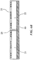
- FIG. 14A is a G-G′ sectional view of FIG. 13
- FIG. 14B is an H-H′ sectional view of FIG. 13 .
- FIG. 1 is a plan view depicting the structure of a semiconductor device of a first embodiment according to the present invention.
- FIG. 2A is an A-A′ sectional view of the semiconductor device depicted in FIG. 1
- FIG. 2B is a B-B′ sectional view of the semiconductor device depicted in FIG. 1 .
- the structure of the semiconductor device of the first embodiment is described with reference to FIG. 1 , FIG. 2A , and FIG. 2B as appropriate.
- the semiconductor device of the first embodiment includes a wiring substrate 10 and a first composite chip 20 .
- the wiring substrate 10 and the first composite chip 20 are wire-bonded by conductive wires 40 .
- the semiconductor device of the first embodiment is configured to have the wiring substrate 10 , the first composite chip 20 , and the wires 40 covered with a sealing resin layer 50 .
- the wiring substrate 10 includes, on its one surface, a plurality of first connection pads 11 , a plurality of second connection pads 12 , a plurality of third connection pads 13 , and a plurality of fourth connection pads 14 exposed from openings of an insulating film.
- the wiring substrate 10 is configured of, for example, an insulating base material with both surfaces each covered with an insulating film, for example, a solder resist film.
- the wiring substrate 10 includes, on a surface opposite to the surface including the first connection pads 11 and others, lands 90 where solder balls 80 are mounted.
- the first composite chips 20 are configured to have a long side of a first semiconductor chip 21 and a long side of a second semiconductor chip 22 mechanically-connected to each other by a dicing area 23 . Since the dicing area 23 does not include wiring, the first semiconductor chip 21 and the second semiconductor chip 22 are not electrically connected to each other.
- the first composite chip 20 is mounted over the wiring substrate 10 by a first adhesive member 60 , for example, a DAF (Die Attach Film).
- the first composite chip 20 according to the present invention is not restricted to the example in which the long sides of two semiconductor chips are connected to each other.
- the first composite chip 20 may be configured to have two or more semiconductor chips connected to each other by a dicing area, or to have short sides of the semiconductor chips connected to each other by a dicing area, for example.
- the dicing area 23 has a width on the order of 20 ⁇ m to 80 ⁇ m.
- a clearance between semiconductor chips is required to be at least on the order of 200 ⁇ m. Therefore, the first composite chip 20 according to the present invention having the first semiconductor chip 21 and the second semiconductor chip 22 connected to each other by the dicing area 23 can configure the small wiring substrate 10 compared with the case in which semiconductor chips are individually mounted over the wiring substrate. That is, since the size of the wiring substrate 10 can be reduced, the size of the semiconductor device of the first embodiment according to the present invention can be reduced.
- first semiconductor chip 21 and the second semiconductor chip 22 each include, on one surface, a plurality of first electrode pads 24 along one short side and a plurality of second electrode pads 25 along the other short side.
- the first and second electrode pads of the second semiconductor chip are arranged in a same layout as the first and second electrode pads of the first semiconductor chip.
- the number of second electrode pads 25 included in each of the first semiconductor chip 21 and the second semiconductor chip 22 is more than the number of first electrode pads 24 .
- a passivation film (protective layer) is formed to protect a circuit formation surface so that the first electrode pads 24 and the second electrode pads 25 are exposed.
- the first connection pads 11 and the first electrode pads 24 included in the first semiconductor chip 21 are wire-bonded by the conductive wires 40 .
- the second connection pads 12 and the second electrode pads 25 included in the first semiconductor chip 21 are wire-bonded by the conductive wires 40 . With this, the wiring substrate 10 and the first semiconductor chip 21 are electrically connected to each other.
- connection pads 13 and the first electrode pads 24 included in the second semiconductor chip 22 are wire-bonded by the conductive wires 40 .
- the fourth connection pads 14 and the second electrode pads 25 included in the second semiconductor chip 22 are wire-bonded by the conductive wires 40 .
- the third connection pads 13 are arranged at positions where a distance from the third connection pads 13 to the first electrode pads 24 included in the second semiconductor chip 22 is longer than a distance from the first connection pads 11 to the first electrode pads 24 included in the first semiconductor chip 21 .
- the first composite chip 20 is mounted so that a space on the short side including the first electrode pads 24 over the wiring substrate 10 is wider than a space on the short side including the second electrode pads 25 . By widening the space on the first electrode pad 24 side with more pads, wire routing can be easily made.
- FIG. 3 is a block diagram depicting an example of the structure of the composite chip according to the present invention.
- the example of the composite chip according to the present invention is described in detail with reference to FIG. 3 as appropriate.
- the composite chip according to the present invention is, for example, a composite chip comprising a single semiconductor substrate that is connected two semiconductor chips by a dicing area.
- the semiconductor chips each having a DRAM (Dynamic Random Access Memory) circuit formed thereon.
- the composite chip has a first memory chip 200 and a second memory chip 300 connected to each other by a dicing area.
- the first memory chip 200 and the second memory chip 300 each have a similar memory circuit area (a circuit formation area) which functions independently.
- the first memory chip 200 is described as an example.
- the first memory chip 200 includes a plurality of circuit blocks, for example, a memory cell array 210 , a row control circuit 220 , a column control circuit 230 , an access control circuit 240 , an input/output control circuit 250 , and an impedance control circuit 260 .
- the memory cell array 210 includes a plurality of word lines WL and a plurality of bit lines BL. Also, a memory cell MC is arranged at each of points of intersection of the word lines WL and the bit lines BL.
- the type of memory for use as the memory cell MC is not particularly restrictive.
- As the memory cell MC for example, a DRAM cell, a flash memory cell, a ReRAM (Resistance Random Access Memory) cell, or the like can be used.
- the row control circuit 220 selects a word line WL.
- the column control circuit 230 selects a bit line BL.
- the access control circuit 240 controls operations of the row control circuit 220 and the column control circuit 230 .
- the access control circuit 240 includes an internal clock generating circuit, a command decoder, an address buffer, a mode register, and others.
- a clock signal CLK is externally inputted via a clock terminal 241 .
- a command address signal CA is externally inputted via a command address terminal 242 .
- the access control circuit 240 Based on the clock signal CLK and the command address signal CA, the access control circuit 240 generates various control signals such as, for example, a row control signal RCTL and a column control signal CCTL.
- the access control circuit 240 when the command address signal CA accesses a row address, the access control circuit 240 outputs a row control signal RCTL to the row control circuit 220 .
- the row control circuit 220 selects a word line WL corresponding to the row control signal RCTL.
- the row control signal RCTL includes a row address, a sense amplifier enable signal, and others.
- the access control circuit 240 when the command address signal CA accesses a column address, the access control circuit 240 outputs a column control signal CCTL to the column control circuit 230 .
- the column control circuit 230 selects a bit line BL corresponding to the column control signal CCTL.
- the column control signal CCTL includes a column address, a column switch timing signal, and others.
- the access control circuit 240 outputs an input/output control signal IOCTL to the input/output control circuit 250 at the time of accessing the column address.
- the input/output control signal IOCTL is a signal for controlling an input/output operation for data data, and includes, for example, an input/output timing signal, a driver strength signal, and others.
- the input/output control circuit 250 reads data data from the memory cell array 210 at the time of read operation, and outputs the read data data from a data output terminal DQ to outside. Also, at the time of write operation, the input/output control circuit 250 writes data data inputted from outside to the data input terminal DQ into the memory cell array 210 .
- the access control circuit 240 outputs a code latch signal ZQL to the impedance control circuit 260 when the command address signal CA indicates a first impedance adjustment command. Also, when the command address signal CA indicates a second impedance adjustment command, the access control circuit 240 outputs an impedance adjustment start signal ZQS to the impedance control circuit 260 .
- the access control circuit 240 When receiving a first impedance adjustment command, the access control circuit 240 can output the code latch signal ZQL both at the time of read operation and at the time of write operation. By contrast, when receiving a second impedance adjustment command, the access control circuit 240 cannot output the impedance adjustment start signal ZQS at the time of read operation and at the time of write operation.
- the impedance control circuit 260 generates an impedance adjustment signal DRZQ according to the impedance adjustment command. Also, the impedance control circuit 260 outputs the generated impedance adjustment signal DRZQ to the input/output control circuit 250 .
- the output impedance of the input/output control circuit 250 is adjusted based on the impedance adjustment signal DRZQ.
- FIG. 4A is a plan view depicting part of a semiconductor wafer
- FIG. 4B is a C-C′ sectional view of the semiconductor wafer depicted in FIG. 4A .
- a plurality of semiconductor chips configuring a semiconductor wafer are sectioned by the dicing areas 23 .
- the semiconductor wafer is held on a dicing tape 100 via the first adhesive member 60 , for example, a DAF.
- FIG. 5A is a plan view depicting dicing of the semiconductor wafer according to the present invention
- FIG. 5B is a D-D′ sectional view of the semiconductor wafer depicted in FIG. 5A .
- the semiconductor wafer is cut by, for example, a dicing blade.
- the first composite chip 20 can be formed by cutting the semiconductor wafer for every two semiconductor chips adjacent to each other in a long side direction, that is, cutting every other dicing areas 23 in the long side direction.
- the first composite chip comprising the single semiconductor substrate on which two semiconductor chips are connected by the dicing area is obtained.
- the dicing areas 23 to be cut can be arbitrarily changed. For example, by cutting every other dicing areas in the long side direction and the short side direction, a composition chip having four semiconductor chips connected to each other can be formed. Therefore, in the present invention, a composite chip can be formed only by cutting the semiconductor wafer without adding a new process.
- FIG. 6A is a plan view of a first composite chip 20 obtained by cutting the semiconductor wafer depicted in FIG. 4 and FIG. 5 by the dicing areas 23 .
- FIG. 6B is an E-E′ sectional view of the first composite chip depicted in FIG. 6A .
- the first composite chip 20 includes the first adhesive member 60 on a surface opposite to the surface where the first electrode pads 24 and the second electrode pads 25 are provided.
- FIG. 7A to FIG. 7F are sectional views depicting a flow of assembling the semiconductor device of the first embodiment according to the present invention.
- FIG. 7A to FIG. 7F as appropriate, the assembling flow of the first embodiment of the semiconductor device according to the present invention is described in detail.
- FIG. 7A depicts the wiring substrate 10 .
- the wiring substrate 10 is configured to have both surfaces of an insulating base material each covered with an insulating film.
- the wiring substrate 10 includes the first connection pads 11 to the fourth connection pads 14 on one surface and includes the plurality of lands 90 on the other surface. Also, the wiring substrate 10 is sectioned by dicing lines, and is cut along the dicing lines after completion of assembling.
- FIG. 7B depicts a process of mounting the first composite chip 20 over the wiring substrate 10 .
- the first composite chip 20 is mounted over a product formation area of the wiring substrate 10 via the first adhesive member 60 .
- the first adhesive member 60 for example, a DAF can be used.
- the first composite chip 20 is configured to have the first semiconductor chip 21 and the second semiconductor chip 22 mechanically-connected to each other by the dicing area 23 .
- FIG. 7C depicts a process of wire-bonding the wiring substrate 10 and the first composite chip 20 via the conductive wires 40 .
- the second connection pads 12 are wire-bonded to the second electrode pads 25 included in the first semiconductor chip 21 .
- the first connection pads 11 are wire-bonded to the first electrode pads 24 included in the first semiconductor chip 21 .
- connection pads 14 are wire-bonded to the second electrode pads 25 of the second semiconductor chip 22 .
- third connection pads 13 are wire-bonded to the first electrode pads 24 included in the second semiconductor chip 22 .
- the wiring substrate 10 and the first composite chip 20 are electrically connected to each other.
- FIG. 7D depicts a process of sealing the wiring substrate 10 , the first composite chip 20 , and the wires 40 with resin.
- the wiring substrate 10 , the first composite chip 20 , and the conductive wires 40 are sealed so as to be covered with sealing resin, for example, thermosetting epoxy resin.
- the sealing resin forms the sealing resin layer 50 after curing by heat.
- sealing can be made with resin without consideration of a filling ratio of the sealing resin, thereby allowing an improvement in manufacturing efficiency. Furthermore, with the gap between the semiconductor chips eliminated, warpage or twist of the semiconductor device can be reduced, thereby allowing inhibition of a defect in transportation of the semiconductor device after sealing with resin and a reduction in mounting accuracy of the solder balls.
- FIG. 7E depicts a process of mounting the solder balls 80 .
- the solder balls 80 are mounted over the lands 90 by, for example, a solder ball mounter.
- FIG. 7F depicts a process of dicing the semiconductor device.
- the semiconductor device is cut along the dicing lines by the dicing blade included in a dicing apparatus not depicted.
- FIG. 8 is a plan view of a semiconductor device of a second embodiment according to the present invention
- FIG. 9 is an F-F′ sectional view of the semiconductor device depicted in FIG. 8 .
- the semiconductor device of the second embodiment according to the present invention is described in detail.
- the semiconductor device of the second embodiment includes first rewiring pads 27 along a long side facing a dicing area 23 on one surface of a first semiconductor chip 21 . Also, the semiconductor device includes second rewiring pads 28 along a long side facing the dicing area 23 on one surface of a second semiconductor chip 22 . Furthermore, the semiconductor device of the second embodiment includes a RDL (Re-Distribution Layer) 26 on one surface of each of the first semiconductor chip 21 and the second semiconductor chip 22 .
- the first rewiring pads 27 are rewired by part of the first electrode pads 24 and the RDL (Redistribution wirings) 26 included in the first semiconductor chip 21 .
- the second rewiring pads 28 are rewired by part of the first electrode pads 24 and the RDL 26 of the second semiconductor chip 22 .
- an insulating layer 29 is formed on the RDL 26 formed on each of the first semiconductor chip 21 and the second semiconductor chip 22 .
- the insulating layer 29 insulates the RDL 26 from the surrounding for electrical protection.
- FIG. 10 is a plan view depicting a semiconductor device of a third embodiment according to the present invention.
- the semiconductor device of the third embodiment according to the present invention is described in detail.
- a first semiconductor chip 21 and a second semiconductor chip 22 includes first electrode pads 24 along one long side and second electrode pads 25 along the other long side. Also, the first semiconductor chip 21 and the second semiconductor chip 22 each include first rewiring pads 27 along one short side and second rewiring pads 28 along the other short side.
- the second electrode pads 25 included in the first semiconductor chip 21 are electrically coupled to the first rewiring pads 27 and the second rewiring pads 28 included in the first semiconductor chip 21 by the RDL 26 .
- the first electrode pads 24 of the second semiconductor chip 22 are electrically coupled to the first rewiring pads 27 and the second rewiring pads 28 included in the second semiconductor chip 22 by the RDL 26 .
- the semiconductor device of the third embodiment allows connection between the wiring substrate 10 and the first composite chip 20 even when the first electrode pads 24 and the second electrode pads 25 are included on the long side facing the dicing area 23 .
- FIG. 11 is a sectional view depicting a semiconductor device of a fourth embodiment according to the present invention.
- the semiconductor device of the fourth embodiment according to the present invention is described in detail.
- a wiring substrate 10 includes bump connection pads 130 in place of the first to fourth connection pads 14
- a first composite chip 20 includes bump electrode pads 140 in place of an adhesive member 50 .
- the bump connection pads 130 and the bump electrode pads 140 are electrically coupled to each other by bumps 120 . That is, the first composite chip 20 is not wire-bonded but flip-chip mounted onto the wiring substrate 10 . Also, the bump electrode pads 140 are coated with solder, for example, solder paste, so that the first composite chip 20 can be efficiently flip-chip mounted on the wiring substrate 10 . The solder with which the bump electrode pads 140 is coated forms a solder layer 150 after flip-chip mounting.
- a space between the wiring substrate 10 and the first composite chip 20 is coated with a resin filler 110 which improves resin characteristics.
- the resin filler 110 is an insulator, and also plays a role of electrically protecting the bumps 120 .
- the semiconductor device can be easily manufactured compared with wire bonding. Also, with the first composite chip 20 being flip-chip mounted on the wiring substrate 10 in the semiconductor device of the fourth embodiment, the thickness can be made thinner.
- FIG. 12 is a plan view depicting a semiconductor device of a fifth embodiment according to the present invention.
- the semiconductor device of the fifth embodiment according to the present invention is described in detail.
- the semiconductor device of the fifth embodiment includes a first composite chip 20 having a first semiconductor chip 21 and a second semiconductor chip 22 connected opposite to each other by a dicing area 23 .
- the semiconductor device of the fifth embodiment is configured to have first electrode pads of the first semiconductor chip 21 and the second semiconductor chip 22 arranged to face each other.
- first electrode pads of the first semiconductor chip 21 and the second semiconductor chip 22 arranged to face each other.
- the arrangement of the connection pads on the wiring substrate 10 can be favorably configured, and also the size of the wiring substrate 10 can be reduced.
- FIG. 13 is a plan view depicting a semiconductor device of a sixth embodiment according to the present invention.
- FIG. 14 is a sectional view depicting the semiconductor device of the sixth embodiment according to the present invention. In the following, with reference to FIG. 13 and FIG. 14 as appropriate, the semiconductor device of the sixth embodiment according to the present invention is described in detail.
- the semiconductor device of the sixth embodiment includes a wiring substrate 10 , a first composite chip 20 , and a second composite chip 30 .
- the structure of connection between the wiring substrate 10 and the first composite chip 20 is similar to that of the semiconductor device of the first embodiment, and therefore description is omitted herein.
- the second composite chip 30 is configured to have a third semiconductor chip 31 and a fourth semiconductor chip 32 connected to each other by a dicing area 33 .
- the third semiconductor chip 31 and the fourth semiconductor chip 32 each include third electrode pads 34 and fourth electrode pads 35 .
- the second composite chip 30 is mounted over the first composite chip 20 by a second adhesive member 70 such as, for example, a FOW (Film On Wire).
- the second adhesive member 70 is configured to be thicker than the first adhesive member 60 , and is arranged so as to bury at least part of a plurality of wires for connecting the first composite chip 20 and the wiring substrate 10 to each other.
- the second composite chip 30 has the third semiconductor chip 31 and the fourth semiconductor chip 32 mounted over the first composite chip 20 so as to be stacked over the first semiconductor chip 21 and the second semiconductor chip 22 , respectively.
- the second composite chip 30 may have the third semiconductor chip 31 mounted over the second semiconductor chip 22 and may have the fourth semiconductor chip 32 mounted over the first semiconductor chip 21 .
- two composite chips are mounted in the semiconductor device of the sixth embodiment, this does not restrict the present invention and, for example, a composite chip may further be mounted over the second composite chip 30 .
- Electrical connection between the second composite chip 30 and the wiring substrate 10 is established by connecting the third electrode pads 34 and the fourth electrode pads 35 and respective connection pads included in the wiring substrate 10 corresponding thereto via wires 40 .
- the first composite chip 20 , the second composite chip 30 , and the plurality of wires 40 are configured to be entirely covered with a sealing resin layer 50 .
- the first composite chip 20 and the second composite chip 30 are configured so that the semiconductor chips are connected to each other by a dicing area. Therefore, as with the first embodiment, the size of the semiconductor device can be reduced without consideration of a filling ratio of resin. Furthermore, in the semiconductor device of the sixth embodiment, not only the size but also warpage and twist of the semiconductor device can be reduced. For example, in a semiconductor device in which the first semiconductor chip 21 and the second semiconductor chip 22 are arranged as being separated from each other and a third semiconductor chip 31 and a fourth semiconductor chip 32 are further mounted thereon, the risk of occurrence of a void is increased at the time of filling with resin.
- a step difference is increased every time a composite chip is mounted, and therefore the risk of occurrence of a void is further increased as the number of steps is increased.
- the structure in the semiconductor device of the sixth embodiment is such that the semiconductor chips connected to each other by the dicing area are mounted as being stacked, a groove between the chips is eliminated. Therefore, in the semiconductor device of the sixth embodiment, the occurrence of a void due to a groove between the semiconductor chips can be reduced even if the number of semiconductor chips to be mounted is increased.
- the present invention is not restricted to the embodiments described above, and it goes without saying that the present invention can be variously modified in a range not deviating from the gist of the present invention.
- a composite chip comprising a structure in which at least two semiconductor chips are mechanically-connected to each other by a dicing area.
- a semiconductor device comprising: a wiring substrate; and a first semiconductor chip and a second semiconductor chip that are mounted over a same plane of the wiring substrate, the first semiconductor chip and the second semiconductor chip being mechanically-connected to each other by a dicing area to form a first composite chip.
- the semiconductor device as claimed in Note 3 further comprising: a third semiconductor chip and a fourth semiconductor chip provided over the first composite chip, and the third semiconductor chip and the fourth semiconductor chip are mechanically-connected to each other by a dicing area to form a second composite chip.
- each of the first semiconductor chip and the second semiconductor chip is a semiconductor chip in a shape of a substantially rectangular plate and having a similar circuit configuration, and long sides of the first semiconductor chip and the second semiconductor chip face each other to be connected by the dicing area.
- a vertical distance between one short side of each of the first semiconductor chip and the second semiconductor chip and an edge of the wiring substrate facing the one short side is larger than a vertical distance between another short side of each of the first semiconductor chip and the second semiconductor chip and an edge of the wiring substrate facing the other short side.
- the wiring substrate has a plurality of first connection pads electrically coupled to a plurality of electrode pads of the first semiconductor chip and a plurality of second connection pads electrically coupled to a plurality of electrode pads of the second semiconductor chip, and a connection distance between the plurality of electrode pads and the plurality of second connection pads of the second semiconductor chip is larger than a connection distance between the plurality of electrode pads and the plurality of first connection pads of the first semiconductor chip.
- a semiconductor device comprising: a wiring substrate; and a composite chip including a plurality of semiconductor chips by a dicing area, the composite chip being mounted on the wiring substrate.
- each of the plurality of semiconductor chips forming the composite chip is a semiconductor chip in a substantially rectangular shape and having a similar circuit configuration.
- a method of manufacturing a semiconductor device comprising: cutting, from out of a semiconductor wafer where a plurality of semiconductor chips are formed, a first composite chip including a first semiconductor chip and a second semiconductor chip mechanically-connected to each other by a dicing area; and mounting the first composite chip over a wiring substrate.
- the method as claimed in Note 14, further comprising: cutting, from out of the semiconductor wafer, a second composite chip including a third semiconductor chip and a fourth semiconductor chip mechanically-connected to each other by a dicing area; and stacking the second composite chip stacked over the first composite chip.
- the method as claimed in Note 16 further comprising: forming a sealing resin layer over the wiring substrate so as to cover the first and second composite chips.
- each of the first semiconductor chip and the second semiconductor chip is a semiconductor chip in a shape of a substantially rectangular plate and having a similar circuit configuration, and long sides of the first semiconductor chip and the second semiconductor chip face each other to be connected by the dicing area.
- the wiring substrate has a plurality of first connection pads electrically coupled to a plurality of electrode pads of the first semiconductor chip and a plurality of second connection pads electrically coupled to a plurality of electrode pads of the second semiconductor chip, and a connection distance between the plurality of electrode pads and the plurality of second connection pads of the second semiconductor chip is larger than a connection distance between the plurality of electrode pads and the plurality of first connection pads of the first semiconductor chip.
Abstract
Description
Claims (13)
Priority Applications (1)
| Application Number | Priority Date | Filing Date | Title |
|---|---|---|---|
| US15/816,949 US11069655B2 (en) | 2013-10-22 | 2017-11-17 | Semiconductor device including two or more chips mounted over wiring substrate |
Applications Claiming Priority (8)
| Application Number | Priority Date | Filing Date | Title |
|---|---|---|---|
| JP2013218905 | 2013-10-22 | ||
| JP2013218905 | 2013-10-22 | ||
| JP2013-218905 | 2013-10-22 | ||
| JP2014111402A JP2015109408A (en) | 2013-10-22 | 2014-05-29 | Composite chip, semiconductor device, and manufacturing method of semiconductor device |
| JP2014-111402 | 2014-05-29 | ||
| JP2014111402 | 2014-05-29 | ||
| US14/519,753 US9837377B2 (en) | 2013-10-22 | 2014-10-21 | Semiconductor device including two or more chips mounted over wiring substrate |
| US15/816,949 US11069655B2 (en) | 2013-10-22 | 2017-11-17 | Semiconductor device including two or more chips mounted over wiring substrate |
Related Parent Applications (1)
| Application Number | Title | Priority Date | Filing Date |
|---|---|---|---|
| US14/519,753 Division US9837377B2 (en) | 2013-10-22 | 2014-10-21 | Semiconductor device including two or more chips mounted over wiring substrate |
Publications (2)
| Publication Number | Publication Date |
|---|---|
| US20180076173A1 US20180076173A1 (en) | 2018-03-15 |
| US11069655B2 true US11069655B2 (en) | 2021-07-20 |
Family
ID=52825484
Family Applications (2)
| Application Number | Title | Priority Date | Filing Date |
|---|---|---|---|
| US14/519,753 Active US9837377B2 (en) | 2013-10-22 | 2014-10-21 | Semiconductor device including two or more chips mounted over wiring substrate |
| US15/816,949 Active US11069655B2 (en) | 2013-10-22 | 2017-11-17 | Semiconductor device including two or more chips mounted over wiring substrate |
Family Applications Before (1)
| Application Number | Title | Priority Date | Filing Date |
|---|---|---|---|
| US14/519,753 Active US9837377B2 (en) | 2013-10-22 | 2014-10-21 | Semiconductor device including two or more chips mounted over wiring substrate |
Country Status (2)
| Country | Link |
|---|---|
| US (2) | US9837377B2 (en) |
| JP (1) | JP2015109408A (en) |
Families Citing this family (5)
| Publication number | Priority date | Publication date | Assignee | Title |
|---|---|---|---|---|
| US10020252B2 (en) * | 2016-11-04 | 2018-07-10 | Micron Technology, Inc. | Wiring with external terminal |
| US10141932B1 (en) | 2017-08-04 | 2018-11-27 | Micron Technology, Inc. | Wiring with external terminal |
| US10304497B2 (en) | 2017-08-17 | 2019-05-28 | Micron Technology, Inc. | Power supply wiring in a semiconductor memory device |
| KR20210047413A (en) * | 2019-10-21 | 2021-04-30 | 삼성전자주식회사 | Flash memory device and computing device incuding flash meory cells |
| US11270759B2 (en) * | 2019-10-21 | 2022-03-08 | Samsung Electronics Co., Ltd. | Flash memory device and computing device including flash memory cells |
Citations (9)
| Publication number | Priority date | Publication date | Assignee | Title |
|---|---|---|---|---|
| JP2000315776A (en) | 1999-05-06 | 2000-11-14 | Hitachi Ltd | Semiconductor device |
| US20040164385A1 (en) * | 2001-06-07 | 2004-08-26 | Yoshiyuki Kado | Semiconductor device and manufacturing method thereof |
| US20090194850A1 (en) | 2008-02-01 | 2009-08-06 | Erdem Kaltalioglu | Crack Stops for Semiconductor Devices |
| US20090212425A1 (en) * | 2008-02-25 | 2009-08-27 | Renesas Technology Corp. | Semiconductor device and a method of manufacturing the same |
| US20110156232A1 (en) * | 2009-12-30 | 2011-06-30 | Sunpil Youn | Semiconductor memory device, semiconductor package and system having stack-structured semiconductor chips |
| US20110287607A1 (en) | 2010-04-02 | 2011-11-24 | Electro Scientific Industries, Inc. | Method and apparatus for improved wafer singulation |
| US20120273971A1 (en) | 2011-04-26 | 2012-11-01 | Elpida Memory, Inc. | Semiconductor device and method of manufacturing the same |
| US20130280826A1 (en) * | 2010-02-16 | 2013-10-24 | Deca Technologies Inc. | Adaptive patterning for panelized packaging |
| US20150069576A1 (en) * | 2013-09-12 | 2015-03-12 | Infineon Technologies Ag | Semiconductor Device and Method for Manufacturing a Semiconductor Device |
-
2014
- 2014-05-29 JP JP2014111402A patent/JP2015109408A/en active Pending
- 2014-10-21 US US14/519,753 patent/US9837377B2/en active Active
-
2017
- 2017-11-17 US US15/816,949 patent/US11069655B2/en active Active
Patent Citations (11)
| Publication number | Priority date | Publication date | Assignee | Title |
|---|---|---|---|---|
| JP2000315776A (en) | 1999-05-06 | 2000-11-14 | Hitachi Ltd | Semiconductor device |
| US6388318B1 (en) | 1999-05-06 | 2002-05-14 | Hitachi, Ltd. | Surface mount-type package of ball grid array with multi-chip mounting |
| US20040164385A1 (en) * | 2001-06-07 | 2004-08-26 | Yoshiyuki Kado | Semiconductor device and manufacturing method thereof |
| US20090194850A1 (en) | 2008-02-01 | 2009-08-06 | Erdem Kaltalioglu | Crack Stops for Semiconductor Devices |
| US20090212425A1 (en) * | 2008-02-25 | 2009-08-27 | Renesas Technology Corp. | Semiconductor device and a method of manufacturing the same |
| US20110156232A1 (en) * | 2009-12-30 | 2011-06-30 | Sunpil Youn | Semiconductor memory device, semiconductor package and system having stack-structured semiconductor chips |
| US20130280826A1 (en) * | 2010-02-16 | 2013-10-24 | Deca Technologies Inc. | Adaptive patterning for panelized packaging |
| US20110287607A1 (en) | 2010-04-02 | 2011-11-24 | Electro Scientific Industries, Inc. | Method and apparatus for improved wafer singulation |
| US20120273971A1 (en) | 2011-04-26 | 2012-11-01 | Elpida Memory, Inc. | Semiconductor device and method of manufacturing the same |
| JP2012230981A (en) | 2011-04-26 | 2012-11-22 | Elpida Memory Inc | Semiconductor device and manufacturing method of the same |
| US20150069576A1 (en) * | 2013-09-12 | 2015-03-12 | Infineon Technologies Ag | Semiconductor Device and Method for Manufacturing a Semiconductor Device |
Also Published As
| Publication number | Publication date |
|---|---|
| US20180076173A1 (en) | 2018-03-15 |
| US20150108637A1 (en) | 2015-04-23 |
| JP2015109408A (en) | 2015-06-11 |
| US9837377B2 (en) | 2017-12-05 |
Similar Documents
| Publication | Publication Date | Title |
|---|---|---|
| US11069655B2 (en) | Semiconductor device including two or more chips mounted over wiring substrate | |
| US10811387B2 (en) | Methods of operating microelectronic devices including a controller | |
| US7598617B2 (en) | Stack package utilizing through vias and re-distribution lines | |
| US7768115B2 (en) | Stack chip and stack chip package having the same | |
| US8952513B2 (en) | Stack type semiconductor package and method of fabricating the same | |
| US10658332B2 (en) | Stack packages including bridge dies | |
| US10002853B2 (en) | Stacked semiconductor package having a support and method for fabricating the same | |
| KR20080002073A (en) | Stack chip having redistributed chip pad and stack chip package using the same | |
| US10756062B2 (en) | Semiconductor chip and semiconductor package including the same | |
| US8338962B2 (en) | Semiconductor package substrate and semiconductor package having the same | |
| US20130114323A1 (en) | Semiconductor device and data storage apparatus | |
| KR20210101802A (en) | Semiconductor packages and method of manufacturing semiconductor packages | |
| US10651132B2 (en) | Semiconductor device | |
| US20150214178A1 (en) | Microelectronic unit and package with positional reversal | |
| US20230343752A1 (en) | Semiconductor package | |
| US11791303B2 (en) | Semiconductor package including semiconductor chips | |
| JPH03194954A (en) | Semiconductor device and electronic device mounted with the semiconductor device | |
| US20230122804A1 (en) | Semiconductor package and a method of manufacturing the semiconductor package | |
| US20230413585A1 (en) | Semiconductor package and method of manufacturing the semiconductor package | |
| TWI543317B (en) | Semiconductor device | |
| JP2006040983A (en) | Method of manufacturing semiconductor device |
Legal Events
| Date | Code | Title | Description |
|---|---|---|---|
| FEPP | Fee payment procedure |
Free format text: ENTITY STATUS SET TO UNDISCOUNTED (ORIGINAL EVENT CODE: BIG.); ENTITY STATUS OF PATENT OWNER: LARGE ENTITY |
|
| AS | Assignment |
Owner name: MICRON TECHNOLOGY, INC., IDAHO Free format text: ASSIGNMENT OF ASSIGNORS INTEREST;ASSIGNORS:SENSHO USAMI;KAZUHIKO SHIBATA;YUTAKA KAGAYA;REEL/FRAME:045774/0387 Effective date: 20141021 |
|
| STPP | Information on status: patent application and granting procedure in general |
Free format text: NON FINAL ACTION MAILED |
|
| STPP | Information on status: patent application and granting procedure in general |
Free format text: RESPONSE TO NON-FINAL OFFICE ACTION ENTERED AND FORWARDED TO EXAMINER |
|
| STPP | Information on status: patent application and granting procedure in general |
Free format text: FINAL REJECTION MAILED |
|
| STPP | Information on status: patent application and granting procedure in general |
Free format text: ADVISORY ACTION MAILED |
|
| STPP | Information on status: patent application and granting procedure in general |
Free format text: DOCKETED NEW CASE - READY FOR EXAMINATION |
|
| STPP | Information on status: patent application and granting procedure in general |
Free format text: NOTICE OF ALLOWANCE MAILED -- APPLICATION RECEIVED IN OFFICE OF PUBLICATIONS |
|
| STPP | Information on status: patent application and granting procedure in general |
Free format text: PUBLICATIONS -- ISSUE FEE PAYMENT RECEIVED |
|
| STPP | Information on status: patent application and granting procedure in general |
Free format text: PUBLICATIONS -- ISSUE FEE PAYMENT VERIFIED Free format text: AWAITING TC RESP, ISSUE FEE PAYMENT VERIFIED |
|
| STPP | Information on status: patent application and granting procedure in general |
Free format text: PUBLICATIONS -- ISSUE FEE PAYMENT VERIFIED |
|
| STCF | Information on status: patent grant |
Free format text: PATENTED CASE |