US11061274B2 - Backlight module and display device - Google Patents
Backlight module and display device Download PDFInfo
- Publication number
- US11061274B2 US11061274B2 US16/631,178 US201916631178A US11061274B2 US 11061274 B2 US11061274 B2 US 11061274B2 US 201916631178 A US201916631178 A US 201916631178A US 11061274 B2 US11061274 B2 US 11061274B2
- Authority
- US
- United States
- Prior art keywords
- led lamps
- led
- angle
- backlight module
- coupling
- Prior art date
- Legal status (The legal status is an assumption and is not a legal conclusion. Google has not performed a legal analysis and makes no representation as to the accuracy of the status listed.)
- Active
Links
- 238000010168 coupling process Methods 0.000 claims abstract description 125
- 230000008878 coupling Effects 0.000 claims abstract description 124
- 238000005859 coupling reaction Methods 0.000 claims abstract description 124
- 238000009792 diffusion process Methods 0.000 claims abstract description 80
- 239000012788 optical film Substances 0.000 claims abstract description 24
- 238000005286 illumination Methods 0.000 claims description 61
- 239000010408 film Substances 0.000 claims description 57
- 238000006243 chemical reaction Methods 0.000 claims description 42
- 239000004973 liquid crystal related substance Substances 0.000 description 33
- 230000000694 effects Effects 0.000 description 22
- 238000000034 method Methods 0.000 description 6
- 239000002245 particle Substances 0.000 description 6
- 239000000463 material Substances 0.000 description 2
- 238000012986 modification Methods 0.000 description 2
- 230000004048 modification Effects 0.000 description 2
- 238000002834 transmittance Methods 0.000 description 2
- 230000009286 beneficial effect Effects 0.000 description 1
- 238000005516 engineering process Methods 0.000 description 1
- 238000004519 manufacturing process Methods 0.000 description 1
- 229920003229 poly(methyl methacrylate) Polymers 0.000 description 1
- 239000004417 polycarbonate Substances 0.000 description 1
- 229920000515 polycarbonate Polymers 0.000 description 1
- 239000004926 polymethyl methacrylate Substances 0.000 description 1
Images


Classifications
-
- G—PHYSICS
- G02—OPTICS
- G02F—OPTICAL DEVICES OR ARRANGEMENTS FOR THE CONTROL OF LIGHT BY MODIFICATION OF THE OPTICAL PROPERTIES OF THE MEDIA OF THE ELEMENTS INVOLVED THEREIN; NON-LINEAR OPTICS; FREQUENCY-CHANGING OF LIGHT; OPTICAL LOGIC ELEMENTS; OPTICAL ANALOGUE/DIGITAL CONVERTERS
- G02F1/00—Devices or arrangements for the control of the intensity, colour, phase, polarisation or direction of light arriving from an independent light source, e.g. switching, gating or modulating; Non-linear optics
- G02F1/01—Devices or arrangements for the control of the intensity, colour, phase, polarisation or direction of light arriving from an independent light source, e.g. switching, gating or modulating; Non-linear optics for the control of the intensity, phase, polarisation or colour
- G02F1/13—Devices or arrangements for the control of the intensity, colour, phase, polarisation or direction of light arriving from an independent light source, e.g. switching, gating or modulating; Non-linear optics for the control of the intensity, phase, polarisation or colour based on liquid crystals, e.g. single liquid crystal display cells
- G02F1/133—Constructional arrangements; Operation of liquid crystal cells; Circuit arrangements
- G02F1/1333—Constructional arrangements; Manufacturing methods
- G02F1/1335—Structural association of cells with optical devices, e.g. polarisers or reflectors
- G02F1/1336—Illuminating devices
- G02F1/133602—Direct backlight
- G02F1/133603—Direct backlight with LEDs
-
- G—PHYSICS
- G02—OPTICS
- G02F—OPTICAL DEVICES OR ARRANGEMENTS FOR THE CONTROL OF LIGHT BY MODIFICATION OF THE OPTICAL PROPERTIES OF THE MEDIA OF THE ELEMENTS INVOLVED THEREIN; NON-LINEAR OPTICS; FREQUENCY-CHANGING OF LIGHT; OPTICAL LOGIC ELEMENTS; OPTICAL ANALOGUE/DIGITAL CONVERTERS
- G02F1/00—Devices or arrangements for the control of the intensity, colour, phase, polarisation or direction of light arriving from an independent light source, e.g. switching, gating or modulating; Non-linear optics
- G02F1/01—Devices or arrangements for the control of the intensity, colour, phase, polarisation or direction of light arriving from an independent light source, e.g. switching, gating or modulating; Non-linear optics for the control of the intensity, phase, polarisation or colour
- G02F1/13—Devices or arrangements for the control of the intensity, colour, phase, polarisation or direction of light arriving from an independent light source, e.g. switching, gating or modulating; Non-linear optics for the control of the intensity, phase, polarisation or colour based on liquid crystals, e.g. single liquid crystal display cells
- G02F1/133—Constructional arrangements; Operation of liquid crystal cells; Circuit arrangements
- G02F1/1333—Constructional arrangements; Manufacturing methods
- G02F1/1335—Structural association of cells with optical devices, e.g. polarisers or reflectors
- G02F1/1336—Illuminating devices
- G02F1/133602—Direct backlight
- G02F1/133606—Direct backlight including a specially adapted diffusing, scattering or light controlling members
-
- G—PHYSICS
- G02—OPTICS
- G02F—OPTICAL DEVICES OR ARRANGEMENTS FOR THE CONTROL OF LIGHT BY MODIFICATION OF THE OPTICAL PROPERTIES OF THE MEDIA OF THE ELEMENTS INVOLVED THEREIN; NON-LINEAR OPTICS; FREQUENCY-CHANGING OF LIGHT; OPTICAL LOGIC ELEMENTS; OPTICAL ANALOGUE/DIGITAL CONVERTERS
- G02F1/00—Devices or arrangements for the control of the intensity, colour, phase, polarisation or direction of light arriving from an independent light source, e.g. switching, gating or modulating; Non-linear optics
- G02F1/01—Devices or arrangements for the control of the intensity, colour, phase, polarisation or direction of light arriving from an independent light source, e.g. switching, gating or modulating; Non-linear optics for the control of the intensity, phase, polarisation or colour
- G02F1/13—Devices or arrangements for the control of the intensity, colour, phase, polarisation or direction of light arriving from an independent light source, e.g. switching, gating or modulating; Non-linear optics for the control of the intensity, phase, polarisation or colour based on liquid crystals, e.g. single liquid crystal display cells
- G02F1/133—Constructional arrangements; Operation of liquid crystal cells; Circuit arrangements
- G02F1/1333—Constructional arrangements; Manufacturing methods
- G02F1/1335—Structural association of cells with optical devices, e.g. polarisers or reflectors
- G02F1/1336—Illuminating devices
- G02F1/133614—Illuminating devices using photoluminescence, e.g. phosphors illuminated by UV or blue light
Definitions
- the present application relates to the field of display technologies, and in particular, to a backlight module.
- the present invention provides a backlight module, which is used to solve the technical problem that the current backlight module has poor mixing effect.
- the light source comprises at least two LED strips coupled to the back plate, the LED strips comprise a plurality of first LED lamps and a plurality of second LED lamps, and the first LED lamps are disposed in a coupling area;
- a diffusion plate arranged in the receiving cavity and disposed in a light emitting direction of the LED strip, wherein a distance between the diffusion plate and the LED lamps on the LED strip is less than a default value
- the LED lamp which is at an end of the LED strip and adjacent to a coupling position has an illuminating inner diameter on the diffusion plate, and the illuminating inner diameter is greater than an edge length to the coupling position.
- an illumination angle of the LED lamp is a first angle, and the first angle is greater than a threshold value.
- an illumination angle of the first LED lamp is the first angle
- an illumination angle of the second LED lamp is a second angle
- the first angle is greater than the second angle
- illumination angles of the first LED lamp and the second LED lamp are both the first angle.
- a distance between two adjacent first LED lamps is less than a distance between two adjacent second LED lamps.
- the distances between the first LED lamps are different, and the distance between the first LED lamps close to a coupling slit is short.
- the distances between the first LED lamps are the same.
- the distances between the first LED lamps are gradually reduced in a direction toward the coupling slit.
- the first LED lamps are white LED lamps and the second LED lamps are white LED lamps.
- the first LED lamp is a blue LED lamp
- a conversion film is provided in a light emitting direction of the first LED lamp, and the conversion film converts blue light into white light.
- the conversion film is disposed on a side of the diffusion plate close to the LED strip.
- a back plate forming a receiving cavity
- the light source comprises at least two LED strips coupled to the back plate, the LED strips comprise a plurality of first LED lamps and a plurality of second LED lamps, the first LED lamps are disposed in a coupling area, the first LED lamps are white LED lamps, and the second LED lamps are white LED lamps;
- a diffusion plate arranged in the receiving cavity and disposed in a light emitting direction of the LED strip, wherein a distance between the diffusion plate and the LED lamps on the LED strip is less than a default value
- the LED lamp which is at an end of the LED strip and adjacent to a coupling position has an illuminating inner diameter on the diffusion plate, and the illuminating inner diameter is greater than an edge length to the coupling position.
- an illumination angle of the LED lamp is a first angle, and the first angle is greater than a threshold value.
- an illumination angle of the first LED lamp is the first angle
- an illumination angle of the second LED lamp is a second angle
- the first angle is greater than the second angle
- illumination angles of the first LED lamp and the second LED lamp are both the first angle.
- a distance between two adjacent first LED lamps is less than a distance between two adjacent second LED lamps.
- the distances between the first LED lamps are different, and the distance between the first LED lamps close to a coupling slit is short.
- the distances between the first LED lamps are the same.
- the distances between the first LED lamps are gradually reduced in a direction toward the coupling slit.
- the first LED lamps are white LED lamps and the second LED lamps are white LED lamps.
- the first LED lamp is a blue LED lamp
- a conversion film is provided in a light emitting direction of the first LED lamp, and the conversion film converts blue light into white light.
- the conversion film is disposed on a side of the diffusion plate close to the LED strip.
- the beneficial effects of the present invention are as follows:
- the present invention provides a backlight module.
- the backlight module includes a light source, an optical film, a diffusion plate, a back plate, and LED strips disposed on the back plate.
- the back plate forms a receiving cavity.
- the light source is arranged in the receiving cavity and disposed on a bottom surface of the back plate.
- the light source includes at least two coupled LED strips.
- the diffusion plate is arranged in the receiving cavity and disposed in a light emitting direction of the LED strips. A distance between the diffusion plate and LED lamps on the LED strips is less than a default value.
- the optical film is arranged in the receiving cavity and disposed in a light emitting direction of the diffusion plate.
- the LED lamps which are at an end of the LED strips and adjacent to a coupling position have an illuminating inner diameter on the diffusion plate, and the illuminating inner diameter is greater than an edge length to the coupling position.
- the LED lamps which are at an end of the LED strips and adjacent to a coupling position have an illuminating inner diameter on the diffusion plate, and thus improves technical problems of poor light mixing in backlight modules.
- FIG. 1 is a first cross-sectional view of a backlight module according to an embodiment of the present invention.
- FIG. 2 is a second cross-sectional view of the backlight module according to the embodiment of the present invention.
- FIG. 3 is a third cross-sectional view of the backlight module according to the embodiment of the present invention.
- FIG. 4 is a fourth cross-sectional view of the backlight module according to the embodiment of the present invention.
- FIG. 5 is a fifth cross-sectional view of the backlight module according to the embodiment of the present invention.
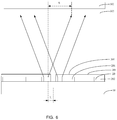
- FIG. 6 is a sixth cross-sectional view of the backlight module according to the embodiment of the present invention.
- FIG. 7 is a seventh cross-sectional view of the backlight module according to the embodiment of the present invention.
- the present invention can solve the problem in the prior art that current backlight modules have poor light mixing effect.
- a coupling area is an area of one or more LED lamps on one side of a coupling slit.
- a distance is a width of a LED lamp plus a gap distance from an adjacent LED lamp.
- a blue LED lamp is an LED lamp that emits blue light
- a white LED lamp is an LED lamp that emits white light.
- S is an inner diameter length projected onto a diffusion film by the first LED lamp close to the coupling slit.
- a distance between the first LED lamp close to the coupling slit and the coupling slit is L.
- a first angle and a second angle are both defined as half of a light emitting angle of the LED lamp.
- a threshold value is an angle value when a light mixing distance becomes small and S is equal to L.
- the back plate 10 forms a receiving cavity.
- the light source is arranged in the receiving cavity and is disposed on a bottom surface of the back plate 10 .
- the light source comprises at least two coupled LED strips 20 .
- the LED strips 20 comprise a plurality of first LED lamps 201 and a plurality of second LED lamps 202 , and the first LED lamps 201 are disposed in a coupling area.
- the diffusion plate 303 is arranged in the receiving cavity and disposed in a light emitting direction of the LED strips 20 .
- the LED lamps which are at an end of the LED strips and adjacent to a coupling position has an illuminating inner diameter on the diffusion plate 303 , and the illuminating inner diameter is greater than an edge length to the coupling position.
- the backlight module includes a light source, an optical film, a diffusion plate, a back plate, and LED strips disposed on the back plate.
- the back plate forms a receiving cavity.
- the light source is arranged in the receiving cavity and disposed on a bottom surface of the back plate.
- the light source includes at least two coupled LED strips.
- the diffusion plate is arranged in the receiving cavity and disposed in a light emitting direction of the LED strips. A distance between the diffusion plate and the LED lamps on the LED strips is less than a default value.
- the optical film is arranged in the receiving cavity and disposed in a light emitting direction of the diffusion plate.
- the LED lamps which are at an end of the LED strips and adjacent to a coupling position has an illuminating inner diameter on the diffusion plate, and the illuminating inner diameter is greater than an edge length to the coupling position.
- the LED lamps which are at an end of the LED strips and adjacent to a coupling position has an illuminating inner diameter on the diffusion plate, and thus improves the light mixing effect and improves the technical problem of poor light mixing effect of the backlight module.
- an illumination angle of the LED lamps is a first angle, and the first angle is greater than a threshold value.
- the threshold value is an angle required when S is equal to L, and an illumination angle of a blue light is an illumination angle of a blue LED lamp without manual processing.
- an illumination angle of the first LED lamp 201 is the first angle R 1
- an illumination angle of a second LED lamp 202 is a second angle R 2
- the first angle R 1 is greater than the second angle R 2 .
- the illumination angle of the first LED lamp 201 in the coupling area is large. When the light mixing distance is a fixed value, the illumination angle of the LED lamp close to the coupling slit is larger, and the light mixing effect is better.
- illumination angles of the first LED lamp 201 and the second LED lamp 202 are both the first angle R 1 .
- the illumination angle is made larger than the natural illumination angle of the white LED lamp. All of the first LED lamps 201 and the second LED lamps 202 are made into blue LED lamps, and can also achieve a larger illumination angle.
- a distance between two adjacent first LED lamps 201 is less than a distance between two adjacent second LED lamps 202 . It can only change the distances of the first LED lamps 201 close to the coupling position. The small distance can make the number of LED lights set per unit area greater, obtaining more light intensity while improving the light mixing effect.
- the distances between the first LED lamps 201 are gradually reduced in a direction toward the coupling slit. This arrangement allows for a denser setting of the LED lamps close to the coupling slits. Under a same voltage, the LED light setting density is higher and the light mixing effect is better when the illumination angle is constant.
- the distances between the first LED lamps are different, and the distance between the first LED lamps close to a coupling slit is short.
- the distances between the first LED lamps 201 are the same, and the first LED lamps 201 have uniform density in the coupling area.
- the distance between two adjacent first LED lamps 201 is the same, the process is easier to implement, and the cost is saved.
- the first LED lamps 201 are white LED lamps
- the second LED lamps 202 are white LED lamps.
- the first LED lamps 201 and the second LED lamps 202 are both set as white LED lamps to make the process simpler and more common.
- the embodiment can also achieve better light mixing effect by improving the distance or the illuminating angle of the first LED lamps 201 .
- the first LED lamps 201 are blue LED lamps
- a conversion film 301 is provided in a light emitting direction of the first LED lamps 201
- the conversion film 301 converts blue light into white light.
- the conversion film 301 can be coated in a non-light board area. The blue light emitted by the blue LED lamps turns white light through luminescent particles.
- the conversion film 301 is disposed on a side of the diffusion plate 303 close to the LED strips 20 .
- the blue light emitted by the blue LED lamps passes through the luminescent particles disposed on one side of the diffusion plate to become white light, and does not affect the normal illumination of the display panel.
- the whole conversion film 301 is disposed on one side of the diffusion plate. Because the normal coupling scheme is that the conversion film 301 is disposed on the blue LED lamps to form white LED lamps, and then through the coupling, the conversion film 301 at the coupling portion may have a problem that a fluorescent film is broken, affecting the continuity of the light and also causing dark lines.
- the film formed by the conversion film 301 can be a continuous film on the entire surface, which alleviates the problem of the fracture of the fluorescent film at the coupling.
- the first LED lamps 201 and the second LED lamps 202 are white LED lamps, and the conversion film 301 is coated on the blue LED lamps to form a whole layer of white LED lamps.
- the second LED lamps 202 are white LED lamps, and the conversion film 301 is coated on the second LED lamps 202 to form a whole layer of white LED lamps.
- the present invention further provides a liquid crystal display panel comprising a backlight module and a display screen.
- the backlight module comprises a light source, an optical film 302 , a diffusion plate 303 , a back plate 10 , and LED strips on the back plate 10 .
- the back plate 10 forms a receiving cavity.
- the light source is arranged in the receiving cavity and is disposed on a bottom surface of the back plate 10 .
- the light source comprises at least two coupled LED strips 20 .
- the LED strips 20 comprise a plurality of first LED lamps 201 and a plurality of second LED lamps 202 , and the first LED lamps 201 are disposed in a coupling area.
- the diffusion plate 303 is arranged in the receiving cavity and disposed in a light emitting direction of the LED strips 20 .
- a distance between the diffusion plate and the LED lamps on the LED strips 20 is less than a default value.
- the optical film 302 is arranged in the receiving cavity and disposed in a light emitting direction of the diffusion plate 303 .
- the LED lamp which is at an end of the LED strips and adjacent to a coupling position has an illuminating inner diameter on the diffusion plate 303 , and the illuminating inner diameter is greater than an edge length to the coupling position.
- the liquid crystal display panel comprises the backlight module and the display screen.
- the backlight module comprises the light source, the optical film 302 , the diffusion plate 303 , the back plate 10 , and the LED strips on the back plate 10 .
- the back plate 10 forms the receiving cavity.
- the light source is arranged in the receiving cavity and is disposed on the bottom surface of the back plate 10 .
- the light source comprises the at least two coupled LED strips 20 .
- the LED strips 20 comprise the plurality of first LED lamps 201 and the plurality of second LED lamps 202 , and the first LED lamps 201 are disposed in the coupling area.
- the diffusion plate 303 is arranged in the receiving cavity and disposed in the light emitting direction of the LED strips 20 .
- the distance between the diffusion plate and the LED lamps on the LED strips 20 is less than the default value.
- the optical film 302 is arranged in the receiving cavity and disposed in the light emitting direction of the diffusion plate 303 .
- the LED lamps which are at the end of the LED strips and adjacent to the coupling position have the illuminating inner diameter on the diffusion plate 303 , and the illuminating inner diameter is greater than the edge length to the coupling position.
- the first LED lamps 201 close to the coupling slit have the illuminating inner diameter on the diffusion plate 303 , and the illuminating inner diameter is greater than the edge length to the coupling position, which improves the light mixing effect and improves the technical problem of poor light mixing effect of the backlight module.
- an illumination angle of the LED lamp in the liquid crystal display panel, as shown in FIG. 2 , in the coupling area, is a first angle, and the first angle is greater than a threshold value.
- An illumination angle of blue light is usually greater than an illumination angle of white light, and the illumination angle of the blue light is an illumination angle of a blue LED lamp without manual processing.
- an illumination angle of the first LED lamp 201 is a first angle R 1
- an illumination angle of the second LED lamp 202 is a second angle R 2
- the first angle R 1 is greater than the second angle R 2 .
- the illumination angle of the first LED lamp 201 in the coupling area is large. When the light mixing distance is a fixed value, the illumination angle of the LED lamp close to the coupling slit is larger, and the light mixing effect is better.
- illumination angles of the first LED lamp 201 and the second LED lamp 202 are both the first angle R 1 .
- the illumination angle is made larger than the natural illumination angle of the white LED lamp. All of the first LED lamps 201 and the second LED lamps 202 are made into blue LED lamps, and can also achieve a larger illumination angle.
- a distance between two adjacent first LED lamps 201 is less than a distance between two adjacent second LED lamps 202 . It can only change the distances of the first LED lamps 201 close to the coupling position. The small distance can make the number of LED lights set per unit area greater, obtaining more light intensity and improving the light mixing effect.
- the distances between the first LED lamps 201 are gradually reduced in a direction toward the coupling slit. This arrangement allows for a denser setting of the LEDs close to the coupling slits. Under a same voltage, the LED light setting density is higher and the light mixing effect is better when the illumination angle is constant.
- the distances between the first LED lamps 201 are the same, and the first LED lamps 201 have uniform density in the coupling area.
- the distance between two adjacent first LED lamps 201 is the same, the process is easier to implement, and the cost is saved.
- the first LED lamps 201 are white LED lamps
- the second LED lamps 202 are white LED lamps.
- the first LED lamps 201 and the second LED lamps 202 are both set as white LED lamps to make the process simpler and more common.
- the embodiment can also achieve better light mixing effect by improving the distance or the illuminating angle of the first LED lamps 201 .
- the first LED lamps 201 are blue LED lamps
- a conversion film 301 is provided in a light emitting direction of the first LED lamps 201
- the conversion film 301 converts blue light into white light.
- the conversion film 301 can be coated in a non-light board area. The blue light emitted by the blue LED lamps turns white light through luminescent particles.
- the conversion film 301 is disposed on a side of the diffusion plate 303 close to the LED strips 20 .
- the blue light emitted by the blue LED lamps passes through the luminescent particles disposed on one side of the diffusion plate to become white light, and does not affect the normal illumination of the display panel.
- the whole conversion film 301 is disposed on one side of the diffusion plate. Because the normal coupling scheme is that the conversion film 301 is disposed on the blue LED lamps to form white LED lamps, and then through the coupling, the conversion film 301 at the coupling portion may have a problem that a fluorescent film is broken, affecting the continuity of the light and also causing dark lines.
- the film formed by the conversion film 301 can be a continuous film on the entire surface, which alleviates the problem of the fracture of the fluorescent film at the coupling.
- the first LED lamps 201 and the second LED lamps 202 are white LED lamps, and the conversion film 301 is coated on the blue LED lamps to form a whole layer of white LED lamps.
- the second LED lamps 202 are white LED lamps, and the conversion film 301 is coated on the second LED lamps 202 to form a whole layer of white LED lamps.
- the present invention further provides a liquid crystal display device comprising a liquid crystal display panel.
- the liquid crystal display panel comprises a backlight module and a display screen.
- the backlight module comprises a light source, an optical film 302 , a diffusion plate 303 , a back plate 10 , and LED strips on the back plate 10 .
- the back plate 10 forms a receiving cavity.
- the light source is arranged in the receiving cavity and is disposed on a bottom surface of the back plate 10 .
- the light source comprises at least two coupled LED strips 20 .
- the LED strips 20 comprise a plurality of first LED lamps 201 and a plurality of second LED lamps 202 , and the first LED lamps 201 are disposed in a coupling area.
- the diffusion plate 303 is arranged in the receiving cavity and disposed in a light emitting direction of the LEDs strip 20 . A distance between the diffusion plate and the LED lamps on the LED strips 20 is less than a default value.
- the optical film 302 is arranged in the receiving cavity and disposed in a light emitting direction of the diffusion plate 303 . Wherein, the LED lamps which are at an end of the LED strips and adjacent to a coupling position have an illuminating inner diameter on the diffusion plate 303 , and the illuminating inner diameter is greater than an edge length to the coupling position.
- the liquid crystal display device comprises the liquid crystal display panel, and the liquid crystal display panel comprises the backlight module and the display screen.
- the backlight module comprises the light source, the optical film 302 , the diffusion plate 303 , the back plate 10 , and the LED strips on the back plate 10 .
- the back plate 10 forms the receiving cavity.
- the light source is arranged in the receiving cavity and is disposed on the bottom surface of the back plate 10 .
- the light source comprises the at least two coupled LED strips 20 .
- the LED strips 20 comprise the plurality of first LED lamps 201 and the plurality of second LED lamps 202 , and the first LED lamps 201 are disposed in the coupling area.
- the diffusion plate 303 is arranged in the receiving cavity and disposed in the light emitting direction of the LED strips 20 .
- the distance between the diffusion plate and the LED lamps on the LED strips 20 is less than the default value.
- the optical film 302 is arranged in the receiving cavity and disposed in the light emitting direction of the diffusion plate 303 .
- the LED lamps which are at the end of the LED strips and adjacent to the coupling position have the illuminating inner diameter on the diffusion plate 303 , and the illuminating inner diameter is greater than the edge length to the coupling position.
- the first LED lamps 201 close to the coupling slit have the illuminating inner diameter on the diffusion plate 303 , and the illuminating inner diameter is greater than the edge length to the coupling position, which improves the light mixing effect and improves the technical problem of poor light mixing effect of the backlight module.
- an illumination angle of the LED lamp in the liquid crystal display device, as shown in FIG. 2 , in the coupling area, is a first angle, and the first angle is greater than a threshold value.
- An illumination angle of blue light is usually greater than an illumination angle of white light, and the illumination angle of the blue light is an illumination angle of a blue LED lamp without manual processing.
- an illumination angle of the first LED lamp 201 is a first angle R 1
- an illumination angle of the second LED lamp 202 is a second angle R 2
- the first angle R 1 is greater than the second angle R 2 .
- the illumination angle of the first LED lamp 201 in the coupling area is large. When a light mixing distance is a fixed value, the illumination angle of the LED lamp close to the coupling slit is larger, and the light mixing effect is better.
- illumination angles of the first LED lamp 201 and the second LED lamp 202 are both the first angle R 1 .
- the illumination angle is made larger than the natural illumination angle of the white LED lamp. All of the first LED lamps 201 and the second LED lamps 202 are made into blue LED lamps, and can also achieve a large illumination angle.
- a distance between two adjacent first LED lamps 201 is less than a distance between two adjacent second LED lamps 202 . It can only change the distances of the first LED lamps 201 close to the coupling position. The small distance can make the number of LED lights set per unit area greater, obtaining more light intensity and improving the light mixing effect.
- the distances between the first LED lamps are different, and the distances between the first LED lamps close to the coupling slit are small.
- the distances between the first LED lamps 201 are gradually reduced in a direction toward the coupling slit. This arrangement allows for a denser setting of the LEDs close to the coupling slits. Under a same voltage, the LED light setting density is higher and the light mixing effect is better when the illumination angle is constant.
- the distances between the first LED lamps 201 are the same, and the first LED lamps 201 have uniform density in the coupling area.
- the distance between adjacent two first LED lamps 201 is the same, the process is easier to implement, and the cost is saved.
- the first LED lamps 201 are white LED lamps
- the second LED lamps 202 are white LED lamps.
- the first LED lamps 201 and the second LED lamps 202 are both set as white LED lamps to make the process simpler and more common.
- the embodiment can also achieve better light mixing effect by improving the distance or the illuminating angle of the first LED lamps 201 .
- the first LED lamps 201 are blue LED lamps
- a conversion film 301 is provided in a light emitting direction of the first LED lamps 201
- the conversion film 301 converts blue light into white light.
- the conversion film 301 can be coated in a non-light board area. The blue light emitted by the blue LED lamps turns white light through luminescent particles.
- the conversion film 301 is disposed on a side of the diffusion plate 303 close to the LED strips 20 .
- the blue light emitted by the blue LED lamps passes through the luminescent particles disposed on one side of the diffusion plate to become white light, and does not affect the normal illumination of the display panel.
- the whole conversion film 301 is disposed on one side of the diffusion plate. Because the normal coupling scheme is that the conversion film 301 is disposed on the blue LED lamp to form a white LED lamp, and then through the coupling, the conversion film 301 at the coupling portion may have a problem that a fluorescent film is broken, affecting the continuity of the light, and also causing dark lines.
- the film formed by the conversion film 301 can be a continuous film on the entire surface, which alleviates the problem of the fracture of the fluorescent film at the coupling.
- the first LED lamps 201 and the second LED lamps 202 are white LED lamps, and the conversion film 301 is coated on the blue LED lamps to form a whole layer of white LED lamps.
- the second LED lamps 202 are white LED lamps, and the conversion film 301 is coated on the second LED lamps 202 to form a whole layer of white LED lamps.
- a large-sized light guide plate is formed by coupling a plurality of small-sized light guide plates.
- the LED chips are distributed in an edge-light manner around each small-sized light guide plate.
- the backlight structure can be reduced, and a single large-sized light guide plate is divided into thousands of small light guide plates, which solves the problem of processing and light propagation of large-sized light guide plates, and reduces the thickness of the backlight.
- dark lines appear at slits between adjacent light guide plates, which affects the uniformity of the entire backlight.
- a proper light mixing distance in the backlight is needed.
- a light mixing distance of more than 3 mm is required, and a thin and light design is difficult to provide sufficient light mixing distance, thereby leading to occurrence of dark lines.
- the present invention makes S greater than or equal to L, and does not affect the light mixing effect and alleviates the dark lines when the light mixing distance is reduced.
- a light mixing layer is disposed between the optical film 302 and the backing plate 10 .
- the transmittance of the light mixing layer is preferably greater than or equal to 90%, and a material of the light mixing layer may be polymethyl methacrylate or polycarbonate. In addition, it can also be made of other materials with higher light transmittance and lighter weight.
- the present invention provides a backlight module.
- the backlight module includes a light source, an optical film, a diffusion plate, a back plate, and LED strips disposed on the back plate.
- the back plate forms a receiving cavity.
- the light source is arranged in the receiving cavity and disposed on a bottom surface of the back plate.
- the light source includes at least two coupled LED strips.
- the diffusion plate is arranged in the receiving cavity and disposed in a light emitting direction of the LED strips. A distance between the diffusion plate and the LED lamps on the LED strips is less than a default value.
- the optical film is arranged in the receiving cavity and disposed in a light emitting direction of the diffusion plate.
- the LED lamps which are at an end of the LED strips and adjacent to a coupling position have an illuminating inner diameter on the diffusion plate, and the illuminating inner diameter is greater than an edge length to the coupling position.
- the LED lamps which are at an end of the LED strips and adjacent to a coupling position have an illuminating inner diameter on the diffusion plate, and thus improves technical problems of poor light mixing in backlight modules.
Landscapes
- Physics & Mathematics (AREA)
- Nonlinear Science (AREA)
- Mathematical Physics (AREA)
- Chemical & Material Sciences (AREA)
- Crystallography & Structural Chemistry (AREA)
- General Physics & Mathematics (AREA)
- Optics & Photonics (AREA)
- Planar Illumination Modules (AREA)
Abstract
Description
Claims (16)
Applications Claiming Priority (3)
| Application Number | Priority Date | Filing Date | Title |
|---|---|---|---|
| CN201910690639.X | 2019-07-29 | ||
| CN201910690639.XA CN110361891B (en) | 2019-07-29 | 2019-07-29 | Backlight module |
| PCT/CN2019/114236 WO2021017229A1 (en) | 2019-07-29 | 2019-10-30 | Backlight module and display device |
Publications (2)
| Publication Number | Publication Date |
|---|---|
| US20210033924A1 US20210033924A1 (en) | 2021-02-04 |
| US11061274B2 true US11061274B2 (en) | 2021-07-13 |
Family
ID=68222699
Family Applications (1)
| Application Number | Title | Priority Date | Filing Date |
|---|---|---|---|
| US16/631,178 Active US11061274B2 (en) | 2019-07-29 | 2019-10-30 | Backlight module and display device |
Country Status (3)
| Country | Link |
|---|---|
| US (1) | US11061274B2 (en) |
| CN (1) | CN110361891B (en) |
| WO (1) | WO2021017229A1 (en) |
Families Citing this family (3)
| Publication number | Priority date | Publication date | Assignee | Title |
|---|---|---|---|---|
| CN110361891B (en) * | 2019-07-29 | 2021-01-15 | 武汉华星光电技术有限公司 | Backlight module |
| CN111913324A (en) * | 2020-08-18 | 2020-11-10 | 深圳市康冠科技股份有限公司 | Mini-LED backlight module and display device |
| CN115047674B (en) | 2022-06-14 | 2023-04-25 | 惠科股份有限公司 | Backlight module and display device |
Citations (13)
| Publication number | Priority date | Publication date | Assignee | Title |
|---|---|---|---|---|
| CN102147074A (en) | 2010-02-10 | 2011-08-10 | 深圳帝光电子有限公司 | Direct type ultrathin LED backlight module |
| CN102537761A (en) | 2010-12-15 | 2012-07-04 | 奇美电子股份有限公司 | Direct type light emitting diode light source |
| US20140111970A1 (en) | 2012-10-19 | 2014-04-24 | Unity Opto Technology Co., Ltd. | Backlight module |
| CN107966825A (en) | 2017-12-26 | 2018-04-27 | 广州弥德科技有限公司 | A kind of splice type directive property backlight and the display system using the backlight |
| US20190043940A1 (en) * | 2017-08-01 | 2019-02-07 | Innolux Corporation | Tile display devices and display devices |
| CN109387981A (en) * | 2018-12-20 | 2019-02-26 | 惠州市华星光电技术有限公司 | A kind of backlight module and liquid crystal display panel |
| CN208606014U (en) | 2018-08-21 | 2019-03-15 | 信利半导体有限公司 | A kind of backlight module |
| CN109613758A (en) | 2019-02-02 | 2019-04-12 | 京东方科技集团股份有限公司 | Backlight Modules and Display Devices |
| CN109656058A (en) | 2019-01-14 | 2019-04-19 | 惠州市华星光电技术有限公司 | A kind of backlight module and its display device |
| CN109782487A (en) | 2019-02-19 | 2019-05-21 | 惠州市华星光电技术有限公司 | Liquid crystal display |
| KR20190060519A (en) | 2017-11-24 | 2019-06-03 | 엘지디스플레이 주식회사 | Optical lens and backlight unit including the same and Liquid crystal display device |
| CN110061116A (en) | 2019-04-29 | 2019-07-26 | 惠州市华星光电技术有限公司 | Mini-LED backlight and preparation method thereof |
| US20200176430A1 (en) | 2016-11-01 | 2020-06-04 | Innolux Corporation | Display devices and methods for forming the same |
Family Cites Families (7)
| Publication number | Priority date | Publication date | Assignee | Title |
|---|---|---|---|---|
| CN203731203U (en) * | 2013-12-26 | 2014-07-23 | Tcl海外电子(惠州)有限公司 | Backlight module, liquid crystal display and television set |
| US10067369B2 (en) * | 2015-11-06 | 2018-09-04 | Champ Vision Display Inc. | Display apparatus with a prism module including a corner prism set disposed on a corner region |
| CN109219770B (en) * | 2016-06-20 | 2022-03-22 | 大日本印刷株式会社 | Light control film, driving method of light control film, light control member, vehicle |
| CN106444158A (en) * | 2016-12-07 | 2017-02-22 | 超亮显示系统(深圳)股份有限公司 | Large-size liquid crystal screen LED matrix direct type highlight backlight module |
| CN208999719U (en) * | 2018-08-30 | 2019-06-18 | 上海九山电子科技有限公司 | LED backlight lamp bar, backlight module and display device |
| CN109976037B (en) * | 2019-04-04 | 2021-12-03 | Tcl华星光电技术有限公司 | Lateral backlight source and display device thereof |
| CN110361891B (en) * | 2019-07-29 | 2021-01-15 | 武汉华星光电技术有限公司 | Backlight module |
-
2019
- 2019-07-29 CN CN201910690639.XA patent/CN110361891B/en active Active
- 2019-10-30 WO PCT/CN2019/114236 patent/WO2021017229A1/en not_active Ceased
- 2019-10-30 US US16/631,178 patent/US11061274B2/en active Active
Patent Citations (16)
| Publication number | Priority date | Publication date | Assignee | Title |
|---|---|---|---|---|
| CN102147074A (en) | 2010-02-10 | 2011-08-10 | 深圳帝光电子有限公司 | Direct type ultrathin LED backlight module |
| CN102537761A (en) | 2010-12-15 | 2012-07-04 | 奇美电子股份有限公司 | Direct type light emitting diode light source |
| US20140111970A1 (en) | 2012-10-19 | 2014-04-24 | Unity Opto Technology Co., Ltd. | Backlight module |
| CN103775905A (en) | 2012-10-19 | 2014-05-07 | 东贝光电科技股份有限公司 | Backlight module |
| US8876316B2 (en) * | 2012-10-19 | 2014-11-04 | Unity Opto Technology Co., Ltd. | Backlight module |
| US20200176430A1 (en) | 2016-11-01 | 2020-06-04 | Innolux Corporation | Display devices and methods for forming the same |
| US20190043940A1 (en) * | 2017-08-01 | 2019-02-07 | Innolux Corporation | Tile display devices and display devices |
| CN109326226A (en) | 2017-08-01 | 2019-02-12 | 群创光电股份有限公司 | Tiled display device and display device |
| KR20190060519A (en) | 2017-11-24 | 2019-06-03 | 엘지디스플레이 주식회사 | Optical lens and backlight unit including the same and Liquid crystal display device |
| CN107966825A (en) | 2017-12-26 | 2018-04-27 | 广州弥德科技有限公司 | A kind of splice type directive property backlight and the display system using the backlight |
| CN208606014U (en) | 2018-08-21 | 2019-03-15 | 信利半导体有限公司 | A kind of backlight module |
| CN109387981A (en) * | 2018-12-20 | 2019-02-26 | 惠州市华星光电技术有限公司 | A kind of backlight module and liquid crystal display panel |
| CN109656058A (en) | 2019-01-14 | 2019-04-19 | 惠州市华星光电技术有限公司 | A kind of backlight module and its display device |
| CN109613758A (en) | 2019-02-02 | 2019-04-12 | 京东方科技集团股份有限公司 | Backlight Modules and Display Devices |
| CN109782487A (en) | 2019-02-19 | 2019-05-21 | 惠州市华星光电技术有限公司 | Liquid crystal display |
| CN110061116A (en) | 2019-04-29 | 2019-07-26 | 惠州市华星光电技术有限公司 | Mini-LED backlight and preparation method thereof |
Also Published As
| Publication number | Publication date |
|---|---|
| CN110361891B (en) | 2021-01-15 |
| WO2021017229A1 (en) | 2021-02-04 |
| US20210033924A1 (en) | 2021-02-04 |
| CN110361891A (en) | 2019-10-22 |
Similar Documents
| Publication | Publication Date | Title |
|---|---|---|
| US8564739B2 (en) | LED backlight system for LCD displays | |
| CN101509619B (en) | Planar illuminating device and display apparatus | |
| US8801219B2 (en) | Backlight assembly having LEDs and side reflectors and display apparatus having the same | |
| CN101324725B (en) | LCD device and backlight device | |
| JP2004206916A (en) | Planar light source | |
| US11061274B2 (en) | Backlight module and display device | |
| EP2531007B1 (en) | Backlight assembly and display apparatus including the same | |
| JP2001042327A (en) | Light guide plate used in parallel and back light using the same | |
| US20050200773A1 (en) | Backlight module and liquid crystal display device | |
| KR20120065756A (en) | Liquid crystal display device | |
| US7494242B2 (en) | Backlight assembly including a diffuser plate having indented portions and a reflective plate having lamp insertion portions | |
| KR20090053629A (en) | Backlight unit and liquid crystal display device having same | |
| KR100879952B1 (en) | Direct Illuminated Backlight Unit | |
| KR20110024270A (en) | Backlight unit and liquid crystal display device having same | |
| KR20050045446A (en) | Back light and method for manufacturing the same | |
| CN201335304Y (en) | LED backlight structure | |
| KR100981276B1 (en) | Back light unit comprising light guide panel | |
| KR20090073433A (en) | Light guide plate and backlight unit including the same | |
| KR102053438B1 (en) | BackLight Unit and Liquid Crystal Display device Comprising The Same | |
| KR101921166B1 (en) | Liquid crystal display device | |
| KR101232144B1 (en) | backlight unit | |
| KR101159496B1 (en) | Back light unit of liquid crystal display device | |
| US20080062704A1 (en) | High uniformity diffuser lens structure | |
| KR20140108056A (en) | Back Light Unit And Liquid Crystal Display Device Comprising The Same | |
| KR20120116576A (en) | Liquid crystal display device |
Legal Events
| Date | Code | Title | Description |
|---|---|---|---|
| AS | Assignment |
Owner name: WUHAN CHINA STAR OPTOELECTRONICS TECHNOLOGY CO., LTD., CHINA Free format text: ASSIGNMENT OF ASSIGNORS INTEREST;ASSIGNOR:LIU, FANCHENG;REEL/FRAME:051515/0255 Effective date: 20190709 |
|
| FEPP | Fee payment procedure |
Free format text: ENTITY STATUS SET TO UNDISCOUNTED (ORIGINAL EVENT CODE: BIG.); ENTITY STATUS OF PATENT OWNER: LARGE ENTITY |
|
| STPP | Information on status: patent application and granting procedure in general |
Free format text: FINAL REJECTION MAILED |
|
| STPP | Information on status: patent application and granting procedure in general |
Free format text: DOCKETED NEW CASE - READY FOR EXAMINATION |
|
| STPP | Information on status: patent application and granting procedure in general |
Free format text: NOTICE OF ALLOWANCE MAILED -- APPLICATION RECEIVED IN OFFICE OF PUBLICATIONS |
|
| STPP | Information on status: patent application and granting procedure in general |
Free format text: PUBLICATIONS -- ISSUE FEE PAYMENT RECEIVED |
|
| STPP | Information on status: patent application and granting procedure in general |
Free format text: PUBLICATIONS -- ISSUE FEE PAYMENT VERIFIED |
|
| STCF | Information on status: patent grant |
Free format text: PATENTED CASE |
|
| MAFP | Maintenance fee payment |
Free format text: PAYMENT OF MAINTENANCE FEE, 4TH YEAR, LARGE ENTITY (ORIGINAL EVENT CODE: M1551); ENTITY STATUS OF PATENT OWNER: LARGE ENTITY Year of fee payment: 4 |