US11056996B2 - Mechanical solar tracker for energy and shade - Google Patents
Mechanical solar tracker for energy and shade Download PDFInfo
- Publication number
- US11056996B2 US11056996B2 US16/791,331 US202016791331A US11056996B2 US 11056996 B2 US11056996 B2 US 11056996B2 US 202016791331 A US202016791331 A US 202016791331A US 11056996 B2 US11056996 B2 US 11056996B2
- Authority
- US
- United States
- Prior art keywords
- sleeve
- cam follower
- solar tracker
- cam
- sun
- Prior art date
- Legal status (The legal status is an assumption and is not a legal conclusion. Google has not performed a legal analysis and makes no representation as to the accuracy of the status listed.)
- Active
Links
- 238000013461 design Methods 0.000 description 41
- 238000000034 method Methods 0.000 description 37
- 239000000463 material Substances 0.000 description 16
- 230000008859 change Effects 0.000 description 4
- 238000013178 mathematical model Methods 0.000 description 4
- 230000007704 transition Effects 0.000 description 4
- 238000004364 calculation method Methods 0.000 description 3
- 238000005259 measurement Methods 0.000 description 3
- 230000007246 mechanism Effects 0.000 description 3
- 230000008569 process Effects 0.000 description 3
- 230000005855 radiation Effects 0.000 description 3
- 238000005070 sampling Methods 0.000 description 3
- 210000005010 torso Anatomy 0.000 description 3
- 230000008901 benefit Effects 0.000 description 2
- 238000006243 chemical reaction Methods 0.000 description 2
- 239000002184 metal Substances 0.000 description 2
- 230000004048 modification Effects 0.000 description 2
- 238000012986 modification Methods 0.000 description 2
- PEDCQBHIVMGVHV-UHFFFAOYSA-N Glycerine Chemical compound OCC(O)CO PEDCQBHIVMGVHV-UHFFFAOYSA-N 0.000 description 1
- 241001465754 Metazoa Species 0.000 description 1
- 239000004677 Nylon Substances 0.000 description 1
- 241001247287 Pentalinon luteum Species 0.000 description 1
- 241000233805 Phoenix Species 0.000 description 1
- 238000009825 accumulation Methods 0.000 description 1
- NIXOWILDQLNWCW-UHFFFAOYSA-N acrylic acid group Chemical group C(C=C)(=O)O NIXOWILDQLNWCW-UHFFFAOYSA-N 0.000 description 1
- 150000001336 alkenes Chemical class 0.000 description 1
- 238000005266 casting Methods 0.000 description 1
- 238000011960 computer-aided design Methods 0.000 description 1
- 238000010276 construction Methods 0.000 description 1
- 230000008878 coupling Effects 0.000 description 1
- 238000010168 coupling process Methods 0.000 description 1
- 238000005859 coupling reaction Methods 0.000 description 1
- 239000004744 fabric Substances 0.000 description 1
- 239000000835 fiber Substances 0.000 description 1
- 229920001903 high density polyethylene Polymers 0.000 description 1
- 239000004700 high-density polyethylene Substances 0.000 description 1
- 230000010354 integration Effects 0.000 description 1
- 238000003698 laser cutting Methods 0.000 description 1
- 238000003754 machining Methods 0.000 description 1
- 229920001778 nylon Polymers 0.000 description 1
- JRZJOMJEPLMPRA-UHFFFAOYSA-N olefin Natural products CCCCCCCC=C JRZJOMJEPLMPRA-UHFFFAOYSA-N 0.000 description 1
- 239000004033 plastic Substances 0.000 description 1
- 229920003023 plastic Polymers 0.000 description 1
- 229920000728 polyester Polymers 0.000 description 1
- 229920000642 polymer Polymers 0.000 description 1
- 238000003860 storage Methods 0.000 description 1
- 125000000391 vinyl group Chemical group [H]C([*])=C([H])[H] 0.000 description 1
- 229920002554 vinyl polymer Polymers 0.000 description 1
- XLYOFNOQVPJJNP-UHFFFAOYSA-N water Substances O XLYOFNOQVPJJNP-UHFFFAOYSA-N 0.000 description 1
- 239000002023 wood Substances 0.000 description 1
Images


Classifications
-
- H—ELECTRICITY
- H02—GENERATION; CONVERSION OR DISTRIBUTION OF ELECTRIC POWER
- H02S—GENERATION OF ELECTRIC POWER BY CONVERSION OF INFRARED RADIATION, VISIBLE LIGHT OR ULTRAVIOLET LIGHT, e.g. USING PHOTOVOLTAIC [PV] MODULES
- H02S20/00—Supporting structures for PV modules
- H02S20/30—Supporting structures being movable or adjustable, e.g. for angle adjustment
- H02S20/32—Supporting structures being movable or adjustable, e.g. for angle adjustment specially adapted for solar tracking
-
- F—MECHANICAL ENGINEERING; LIGHTING; HEATING; WEAPONS; BLASTING
- F16—ENGINEERING ELEMENTS AND UNITS; GENERAL MEASURES FOR PRODUCING AND MAINTAINING EFFECTIVE FUNCTIONING OF MACHINES OR INSTALLATIONS; THERMAL INSULATION IN GENERAL
- F16H—GEARING
- F16H25/00—Gearings comprising primarily only cams, cam-followers and screw-and-nut mechanisms
- F16H25/08—Gearings comprising primarily only cams, cam-followers and screw-and-nut mechanisms for interconverting rotary motion and reciprocating motion
- F16H25/14—Gearings comprising primarily only cams, cam-followers and screw-and-nut mechanisms for interconverting rotary motion and reciprocating motion with reciprocation perpendicular to the axis of rotation
-
- F—MECHANICAL ENGINEERING; LIGHTING; HEATING; WEAPONS; BLASTING
- F16—ENGINEERING ELEMENTS AND UNITS; GENERAL MEASURES FOR PRODUCING AND MAINTAINING EFFECTIVE FUNCTIONING OF MACHINES OR INSTALLATIONS; THERMAL INSULATION IN GENERAL
- F16H—GEARING
- F16H53/00—Cams or cam-followers, e.g. rollers for gearing mechanisms
- F16H53/06—Cam-followers
-
- F—MECHANICAL ENGINEERING; LIGHTING; HEATING; WEAPONS; BLASTING
- F24—HEATING; RANGES; VENTILATING
- F24S—SOLAR HEAT COLLECTORS; SOLAR HEAT SYSTEMS
- F24S30/00—Arrangements for moving or orienting solar heat collector modules
- F24S30/40—Arrangements for moving or orienting solar heat collector modules for rotary movement
- F24S30/45—Arrangements for moving or orienting solar heat collector modules for rotary movement with two rotation axes
- F24S30/452—Vertical primary axis
-
- F—MECHANICAL ENGINEERING; LIGHTING; HEATING; WEAPONS; BLASTING
- F24—HEATING; RANGES; VENTILATING
- F24S—SOLAR HEAT COLLECTORS; SOLAR HEAT SYSTEMS
- F24S30/00—Arrangements for moving or orienting solar heat collector modules
- F24S2030/10—Special components
- F24S2030/13—Transmissions
- F24S2030/137—Transmissions for deriving one movement from another one, e.g. for deriving elevation movement from azimuth movement
-
- F—MECHANICAL ENGINEERING; LIGHTING; HEATING; WEAPONS; BLASTING
- F24—HEATING; RANGES; VENTILATING
- F24S—SOLAR HEAT COLLECTORS; SOLAR HEAT SYSTEMS
- F24S30/00—Arrangements for moving or orienting solar heat collector modules
- F24S2030/10—Special components
- F24S2030/14—Movement guiding means
- F24S2030/145—Tracks
-
- F—MECHANICAL ENGINEERING; LIGHTING; HEATING; WEAPONS; BLASTING
- F24—HEATING; RANGES; VENTILATING
- F24S—SOLAR HEAT COLLECTORS; SOLAR HEAT SYSTEMS
- F24S50/00—Arrangements for controlling solar heat collectors
- F24S50/20—Arrangements for controlling solar heat collectors for tracking
-
- Y—GENERAL TAGGING OF NEW TECHNOLOGICAL DEVELOPMENTS; GENERAL TAGGING OF CROSS-SECTIONAL TECHNOLOGIES SPANNING OVER SEVERAL SECTIONS OF THE IPC; TECHNICAL SUBJECTS COVERED BY FORMER USPC CROSS-REFERENCE ART COLLECTIONS [XRACs] AND DIGESTS
- Y02—TECHNOLOGIES OR APPLICATIONS FOR MITIGATION OR ADAPTATION AGAINST CLIMATE CHANGE
- Y02E—REDUCTION OF GREENHOUSE GAS [GHG] EMISSIONS, RELATED TO ENERGY GENERATION, TRANSMISSION OR DISTRIBUTION
- Y02E10/00—Energy generation through renewable energy sources
- Y02E10/40—Solar thermal energy, e.g. solar towers
- Y02E10/47—Mountings or tracking
-
- Y—GENERAL TAGGING OF NEW TECHNOLOGICAL DEVELOPMENTS; GENERAL TAGGING OF CROSS-SECTIONAL TECHNOLOGIES SPANNING OVER SEVERAL SECTIONS OF THE IPC; TECHNICAL SUBJECTS COVERED BY FORMER USPC CROSS-REFERENCE ART COLLECTIONS [XRACs] AND DIGESTS
- Y02—TECHNOLOGIES OR APPLICATIONS FOR MITIGATION OR ADAPTATION AGAINST CLIMATE CHANGE
- Y02E—REDUCTION OF GREENHOUSE GAS [GHG] EMISSIONS, RELATED TO ENERGY GENERATION, TRANSMISSION OR DISTRIBUTION
- Y02E10/00—Energy generation through renewable energy sources
- Y02E10/50—Photovoltaic [PV] energy
Definitions
- the present disclosure relates to mechanical devices that may be easily adjusted to point towards the sun for the purposes of collecting solar energy or generating shade.
- Solar trackers may be used to maximize solar collection onto a photovoltaic panel, to condense water, generate heat, or to perform other sun-related processes. They may also be used to create optimum shade conditions over a designated location.
- the invention of the present disclosure satisfies the need for a reliable, low-cost, and mechanical solar tracker that is easy to adjust and will provide efficient collection of solar energy and optimal shade at a given location throughout the day.
- the present disclosure in aspects and embodiments addresses these various needs and problems.
- FIG. 1 illustrates an isometric view of an embodiment of a mechanical solar tracker proving
- FIG. 2 is another isometric view of the mechanical solar tracker
- FIG. 3 is an isometric view of another mechanical solar tracker
- FIGS. 4A and 4B illustrate design parameters of a mechanical solar tracker
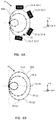
- FIGS. 5A-5F illustrate various embodiments of a positioning cam of a mechanical solar tracker
- FIGS. 6A and 6B illustrate time points on a positioning cam of a mechanical solar tracker
- FIGS. 7A-7C illustrate labels for day paths of a positioning cam of a mechanical solar tracker
- FIGS. 8A and 8B illustrate variables for configuring a positioning cam at a time of day for a mechanical solar tracker
- FIGS. 9A and 9B illustrate variables for configuring a positioning cam at another time of day for a mechanical solar tracker
- FIGS. 10A, 10B, and 10C illustrate possible configurations of a mechanical solar tracker
- FIGS. 11A-11H illustrate various positioning cam paths for eight different locations on Earth.
- the terms “collector”, “shade”, and “surface” may be used interchangeably and may refer to a photovoltaic panel collector, a reflector, a device for collecting solar radiation for conversion to heat or any solar-energy driven process, a material that may provide shade, or any combination of these materials.
- the term “surface” may be used to describe a device suitable for providing shade from the sun, collecting solar energy, or both.
- a surface may be shaped in whatever manner is best suited to the application. For example, the shape of surface may reflect the shape of an area to be shaded.
- a surface designed to provide shade can be constructed out of one or more materials that are designed to protect from the sun, including, for example: nylon, canvas, acrylic, olefin, high density polyethylene fabric, or vinyl-coated polyester.
- the term “translate” can be used to mean following or moving along a particular path.
- the term “vertical axis” may be used to describe an imaginary (non-visible) line that is perpendicular to the ground.
- One or more components of the mechanical solar tracker may rotate about such a line.
- the imaginary line may also serve as a fixed-reference line for the measurement of certain coordinates, as will be described herein.
- positioning cam may be used to refer to any device comprising one or more “paths,” which may also be referred to as “day paths” and are constructed based on the latitude location of the mechanical solar tracker. Such paths comprise the positioning cam's overall surface and shape.
- the paths may be tube-like or cylindrical in structure. Alternatively, they may be fashioned as guides cut from a sheet of material. They may be closed paths forming a closed shape.
- a positioning cam may include a component for coupling each of the paths together at a common point.
- a positioning cam may also include a means for attaching another device to one of the paths.
- a “latitude location” may be a range of latitude locations.
- a mechanical solar tracker may be designed for a specific latitude, e.g., Logan, Utah, USA, with a latitude of approximately 42 degrees, such a solar tracker may be used for latitudes ranging from 40 to 44 (+/ ⁇ two-degrees latitude), 35 to 49 (+/ ⁇ seven-degrees latitude), or 32 to 52 (+/ ⁇ 10-degrees latitude).
- the trade-off for a wider-range design is that a mechanical solar tracker will not track the sun's path as accurately as possible.
- the term “sleeve” may refer to any component comprising an aperture with a circumference suitable for fitting the component around another component.
- the aperture shape may reflect the overall sleeve shape. It may also reflect the shape of component around which the sleeve is to be fitted.
- the component around which the sleeve is to be fitted may be, for example, a pole.
- a sleeve may be configured to rotate with respect to the other component, or it may be configured to remain stationary while the other component rotates with respect to it.
- a sleeve may be cylindrical in shape.
- cam follower refers to any device that may be coupled to a surface and may be configured to translate a path of a positioning cam.
- a cam follower may include one or more upper portions that connect to surface and one or more lower portions that connect to a sleeve.
- a cam follower may be constructed out of a tube-like material. It may be curved; for example, it may have an “S” shape.
- adjustment arm and “rotation drive” may be used interchangeably to refer to any device suitable for rotating a sleeve about a vertical axis, either manually, mechanically, or electro-mechanically.
- a device may be a component extending horizontally from a sleeve with a handle to which a user may apply force in order to achieve rotation of the sleeve.
- Such a device may also be an electric rotator.
- bearing may be used to describe any component that allows for motion between two other components.
- the motion may constitute, but is not limited to, sliding or rotating.
- Such a component may be configured to carry a load while in contact with and moving relative to another component.
- the load may be a cam follower.
- a bearing may be cylindrical or spherical in shape.
- the materials forming a bearing may include, but are not limited to, one or more of the following materials: metal, polymer, plastic, or fiber.
- a bearing as referenced in this disclosure may, in some embodiments, be a tube or sleeve that allows relative motion between two other components, which may also be referred to as a bushing.
- the cardinal directions in the fixed reference frame may be labeled as “N” for north, “S” for south, “E” for east, and “W” for west.
- the cardinal directions and Cartesian axes are provided in the figures to illustrate the orientation of the various mechanical solar trackers.
- the Cartesian axes may be labeled as “x”, “y”, and “z”.
- an axis running from north to south may be referred to as an “x-axis.”
- An axis running from east to west may be referred to as a “y-axis”.
- the term “x-y plane” may refer to an imaginary, two-dimensional surface that extends infinitely along and contains both the x-axis and y-axis.
- the “x-y” plane may also be referred to as a “horizontal plane.”
- the z-axis is a vertical axis and may represent a third vector perpendicular to both the x-axis and the y-axis.
- a rotation about the z-axis in the x-y plane is referred to as an “azimuth” rotation and may be described by an azimuth angle.
- the term “z-r plane” may refer to an infinite, two-dimensional surface that extends infinitely along and contains the z-axis and an orthogonal imaginary axis r which lies along the x-y plane.
- the r-axis is independent of x and y and is invariant to azimuth rotation about vertical z-axis.
- Elevation rotation is about the elevation rotation axis.
- FIG. 1 illustrates a southwest-facing view of mechanical solar tracker 100 as a patio umbrella shading a patio table 3 seating a number of people 1 -N, where N is equal to four people in FIG. 1 .
- Each person is illustrated as a head 1 , and an associated torso 2 .
- the time is 08:00 AM on the 21st of June.
- the location is Utah State University in Logan, Utah, USA.
- the mechanical solar tracker 100 is configured to position surface 10 normal to the sun direction vector 64 A extending from reference point 71 position on a vertical axis 61 to the sun 64 .
- Surface 10 may be a photovoltaic panel collector, a reflector, a device for collecting solar radiation for conversion to heat or any solar-energy driven process, a material that may provide shade, or any combination of these materials.
- the sun direction vector 64 A of the sun 64 in the sky is the vector that points from the reference point 71 to the sun 64 that may be defined by two angles.
- the first of these angles is the sun azimuth angle, ⁇ S (illustrated in FIGS. 8B and 9B ), which may refer to the compass bearing, relative to the true (geographic) south of a point on the horizon directly beneath the sun 64 .
- the second angle is the sun elevation angle ⁇ S (illustrated in FIG. 4 A), the angle measurement between the sun direction vector 64 A and a vector extending from reference point 71 to the point on the horizon directly below the sun 64 (illustrated in FIGS. 4A, 8A and 9A ).
- the “horizon” may refer to a horizontal (“x-y”) plane that contains reference point 71 as well as the point directly below the sun 64 .
- embodiments of the present disclosure may include, but are not limited to, a mechanical solar tracker 100 comprising a positioning cam 30 , a sleeve 24 , a cam follower 40 , and a surface 10 coupled to cam follower 40 .
- the positioning cam 30 may comprise one or more day paths, e.g., 30 A, 30 B, 30 C (or additional day paths), the one or more paths being configured as a function of latitude location of the mechanical solar tracker 100 .
- the sleeve 24 may be coupled to an adjustment arm 25 (shown in FIGS. 2, 3, and 4B ), the adjustment arm 25 operable to rotate the sleeve 24 about a vertical axis 61 .
- Cam follower 40 may be coupled to the sleeve 24 and configured to translate a selected path (in FIG. 1 , the selected path is illustrated as day path 30 A) of the one or more day paths 30 A, 30 B, 30 C as the sleeve 24 rotates about vertical axis 61 .
- the selected path may be configured such that as the sleeve 24 rotates about vertical axis 61 , upper-cam follower 41 maintains surface 10 normal to a vector extending from reference point 71 through surface 10 to the sun 64 , illustrated in FIG. 1 and other figures as sun direction vector 64 A.
- cam follower 40 traces along day path 30 A, which tips surface 10 by an elevation rotation to follow the position of the sun 64 as the sun 64 moves across the sky over a period of time.
- a mechanical solar tracker 100 comprising a positioning cam 30 , a sleeve 24 , a cam follower 40 , and a surface 10 coupled to cam follower 40 .
- the selected path may be configured such that as the sleeve 24 rotates about vertical axis 61 , cam follower 40 optimizes the amount of solar energy collected by surface 10 by tracing the selected path (in FIG. 1 , the selected day path is illustrated as 30 A) as the sun 64 moves across the sky over a period of time.
- Embodiments of the present disclosure may also include methods of constructing a positioning cam 30 . Such methods may include determining one or more sets of contact points 72 -N (e.g., 72 - 1 , 72 - 2 , 72 - 3 , etc.), as a function of a position of the sun 64 relative to a reference point 71 central to a given area 3 (illustrated as a patio table 3 in FIG.
- each set of contact points 72 -N of the one or more sets of points (one for each day path 30 A, 30 B or 30 C for example) is determined based on a specified day of a year and on a latitude location of reference point 71 , each point within each set of points of the one or more sets of points is determined based on a specified time of the specified day of the year.
- Such methods may also comprise constructing one or more paths that comprise the positioning cam 30 , wherein each day path 30 A, 30 B, or 30 C, of the one or more paths comprising positioning cam 30 includes one set of points of the one or more sets of points; selecting a first day path 30 A of the one or more paths; and causing a cam follower 40 to trace the selected day path 30 A.
- the selected day path 30 A may be configured such that as cam follower 40 traces the selected day path 30 A, cam follower 40 maintains surface 10 (which is coupled to cam follower 40 ) normal to the sun direction vector 64 A extending from the sun 64 to reference point 71 as the sun 64 moves across the sky during the specified day of the year.
- the selected day path 30 A may also be configured such that as cam follower 40 traces the selected day path 30 A, cam follower 40 optimizes the amount of solar energy collected or shade provided or both by a surface 10 coupled to cam follower 40 .
- mechanical solar tracker 100 may include a central pole 22 that connects to a positioning cam 30 .
- Central pole 22 may be aligned with vertical axis 61 . It may secure surface 10 to a foundation 4 , which may be the ground, the roof of a building, the deck of a ship, or any other structure that provides a fixed attachment from below.
- Central pole 22 may also be supported from above, such as by an arm connected to a pole that is horizontally offset from vertical axis 61 as part of a pavilion, pergola, cantilever umbrella, or any other structure that provides a fixed attachment point from above. Supports from above and below central pole 22 may be deployed separately or together.
- Surface 10 may be configured to cast shade onto the area below the positioning cam 30 based on the shape of surface 10 .
- Surface 10 may be configured to cast a shade on the opposite side of surface 10 to which the sun 64 is casting light along the sun direction vector 64 A.
- Surface 10 may be shaped to provide constant shade to a specific area or object based on the application. In FIG. 1 , surface 10 is shaped to provide constant shade for all days of the year to the tops of the human torsos 2 -N and their heads 1 -N when the surface 10 is adjusted to face the sun 64 as it moves across the sky.
- the shape of surface 10 may also be designed to provide partial shade for a larger area based on the time of day and date of the year.
- This area may contain a patio table 3 , human heads 1 -N and human torsos 2 -N, or any other object that benefits from shade, such as equipment, crops, animals, or dwellings.
- Surface 10 may also be shaped to collect solar energy from the sun 64 .
- FIG. 2 illustrates another isometric, southwest-facing view of a mechanical solar tracker 100 as a patio umbrella embodiment shading a patio table 3 at 12:30 on the 21 st of June at Utah State University.
- Fixed or non-moving elements of this embodiment may include central pole 22 , which may be connected at its lower end to foundation 4 (which may be the ground) and attached at its upper end to a connecting structure 21 .
- the connecting structure 21 may connect to the positioning cam 30 .
- cam follower 40 may translate one of three day paths 30 A, 30 B or 30 C, the designs of which are described herein.
- Central pole 22 may be fixed to the foundation 4 and pass through a patio table 3 .
- cam follower 40 may be a support assembly comprised of an upper-cam follower 41 and a lower-cam follower 42 .
- Upper-cam follower 41 may be coupled to surface 10 .
- upper-cam follower 41 of cam follower 40 may be fixed to the back of surface 10 .
- Upper-cam follower 41 may also be coupled to a lower-cam follower 42 to form a continuous cam follower 40 .
- Lower-cam follower 42 may be coupled to a sleeve 24 .
- the sleeve 24 may be concentric to central pole 22 and may freely rotate around vertical axis 61 implementing an azimuth rotation.
- central pole 22 may be aligned with vertical axis 61 and may secure the positioning cam 30 to a foundation 4 .
- Lower-cam follower 42 may be configured to allow central pole 22 to pass through it.
- lower-cam follower 42 may be split into two parallel, curved-rod structures, providing a means for central pole 22 to pass between cam follower 40 as cam follower 40 changes positions.
- the two rods of lower-cam follower 42 may connect to the sleeve 24 rotationally in elevation rotation axis 60 .
- Two or more bushings 23 may be connected to the bottom of the lower-cam follower 42 .
- the bushings 23 may each encircle one of two pins that protrude from the sleeve 24 .
- the bushings 23 may rotationally attach surface 10 and cam follower 40 , to the pins about an elevation rotation axis 60 .
- the pins being fixed to the sleeve 24 , may enable rotation of surface 10 and cam follower 40 about the vertical axis 61 , as sleeve 24 rotates about central pole 22 .
- surface 10 may be attached to a cam follower 40 , or upper-cam follower 41 such that it may rotate about an axis, such as elevation rotation axis 60 as well as vertical axis 61 .
- the mechanical sun tracker 100 is depicted at 12:30 on the 21 st of June with surface 10 facing south.
- the mechanical sun tracker 100 is depicted at 08:00 AM on the 21st of June with surface 10 facing east.
- the azimuth rotation needed to transition surface 10 from facing east in FIG. 1 and facing south in FIG. 2 may be implemented by rotation of sleeve 24 about central pole 22 .
- This elevation rotation about elevation rotation axis 60 may be implemented by bushings 23 (illustrated in FIG. 2 ) rotating about the fixed pins protruding from sleeve 24 .
- FIG. 2 also illustrates positioning cam 30 .
- the positioning cam 30 may be comprised of fixed day paths 30 A, 30 B or 30 C that dictate the elevation angle of surface 10 based on the elevation angle of upper-cam follower 41 as it rests at contact point 72 - 1 .
- Each day path 30 A, 30 B, or 30 C may be defined as an array or a list of potential contact points 72 -N that are defined in terms of x, y, and z coordinates in the fixed reference frame of mechanical solar tracker 100 .
- the contact points 72 -N may be defined as a function of a sun azimuth angle ⁇ S and a sun elevation angle ⁇ S .
- Each day path 30 A, 30 B, or 30 C may comprise a number of potential contact points 72 -N. Although three potential contact points 72 - 1 , 72 - 2 , and 72 - 3 are identified in FIGS. 1 and 2 , each day path 30 A, 30 B, or 30 C may be comprised of any number of potential contact points 72 -N. Each day path 30 A, 30 B, or 30 C may be constructed by first determining a number of potential contact points 72 -N and then forming a loop running through each of the contact points 72 -N.
- Each of the potential contact points 72 -N may be determined such that as upper-cam follower 41 rests at a contact point 72 - 1 on a selected day path 30 A comprised potential contact points 72 -N, surface 10 is positioned in a configuration that maximizes solar energy collection, shade, or both.
- the day paths 30 A, 30 B, or 30 C may be configured such that as the sleeve 24 rotates about vertical axis 61 , cam follower 40 maintains surface 10 normal to sun direction vector 64 A by tracing a selected day path out of the day paths 30 A, 30 B, or 30 C.
- the day paths 30 A, 30 B, or 30 C may also be configured such that as the sleeve 24 rotates about vertical axis 61 , cam follower 40 optimizes solar energy collected by surface 10 (which may be a collector) by tracing the selected path of the day paths 30 A, 30 B, or 30 C as sun 64 moves across the sky over a period of time. Maximizing solar energy collection, shade, or both, may require cam follower 40 to hold surface 10 at an elevation angle such that surface 10 is normal to sun direction vector 64 A.
- the contact points 72 -N of the selected day path 30 A are traversed as cam follower 40 rotates about vertical axis 61 of mechanical solar tracker 100 .
- a change in sun azimuth angle ⁇ S of cam follower 40 changes the elevation angle of surface 10 as it rotates about vertical axis 61 at reference point 71 , which is the center of both the azimuth and elevation rotation.
- the day paths 30 A, 30 B, or 30 C may be customized to the latitude of the deployment location of mechanical solar tracker 100 and the day of the year.
- a positioning cam such as positioning cam 30
- the positioning cam 30 through contact with upper-cam follower 41 , may change the elevation angle of surface 10 so that surface 10 is held at an optimal (or near-optimal) elevation angle when adjusted to the correct azimuth angle.
- the optimal elevation angle may be determined based on a day of the year used to generate the day path 30 N and the latitude at which mechanical solar tracker 100 will be deployed.
- the azimuth angle at which surface 10 is positioned may be adjusted through rotation of the sleeve 24 about central pole 22 .
- the sleeve 24 may be connected to lower-cam follower 42 through attached pins that lie within the bushings 23 .
- the sleeve 24 may be coupled to central pole 22 by means of one or more swiveling members, such as upper and lower swivel bearings or members 26 and 27 , which may allow the sleeve 24 to freely rotate about the vertical axis 61 and about central pole 22 .
- the two swivel bearings or members 26 and 27 may support the weight of surface 10 and cam follower 40 , and any additional components of surface support structure 48 (illustrated in FIG. 3 ).
- an adjustment arm 25 may be coupled to the sleeve 24 and may be operable to rotate the sleeve 24 about vertical axis 61 .
- the adjustment arm 25 may be a mechanical or electrical rotation device. Rotating the sleeve 24 about vertical axis 61 through the adjustment arm 25 may cause cam follower 40 to trace the selected day path 30 A of the one or more day paths 30 A, 30 B, or 30 C. Azimuth rotation of surface 10 may also be achieved by the direct movement of any part of cam follower 40 or surface 10 , or any additional components of surface support structure 48 (illustrated in FIG. 3 ).
- the mechanical solar tracker 100 or 102 may be configured such that rotation of sleeve 24 will cause cam follower 40 to travel on the upper and lower swivel bearings or members 26 and 27 circumferentially around the vertical axis 61 .
- an electro-mechanical actuation may be employed through a motor installed in sleeve 24 or central pole 22 .
- An electro-mechanical actuator (positioned in sleeve 24 ) may automatically position the azimuth angle of surface 10 such that surface 10 is normal to the sun direction vector 64 A.
- Cam follower 40 and sleeve 24 may be configured to rotate circumferentially from east to west around vertical axis 61 during daylight, following the trajectory of the sun 64 . Additionally, cam follower 40 and sleeve 24 may be configured to rotate circumferentially from west to east around vertical axis 61 during night-time. This may allow surface 10 to be positioned correctly when the sun 64 rises in the east again the next morning.
- FIG. 3 illustrates an alternative embodiment of cam follower 40 and its attachment to surface 10 within mechanical solar tracker 102 .
- the positioning cam 30 is not illustrated in FIG. 3 .
- the mechanical solar tracker 102 embodiment illustrated in FIG. 3 may include a positioning cam 30 , as illustrated in FIGS. 1 and 2 .
- the sun 64 and sun direction vector 64 A are shown normal to surface 10 .
- cam follower 40 includes an additional support structure, surface support structure 48 , which provides four attachment points between cam follower 40 and surface 10 in contrast to the single attachment point illustrated in FIGS. 1 and 2 .
- upper-cam follower 41 may not connect directly to surface 10 .
- Azimuth rotation 61 A actuation (illustrated in FIG. 4B ) may be achieved through movement of surface support structure 48 , which is attached to surface 10 and cam follower 40 .
- Surface 10 may be shaped circularly, rectangularly, or in any other fashion.
- the shape of surface 10 may be determined by aesthetic and engineering considerations.
- surface 10 may be shaped in a manner that optimizes the solar radiation collected by surface 10 .
- Surface 10 may also have a shape that matches a shape of an area that is to be shaded.
- Surface 10 may also be broken up into multiple surfaces, as illustrated in FIG. 3 .
- surface 10 may be comprised of two distinct surfaces 10 - 1 and 10 - 2 that are mechanically coupled to move together.
- surface 10 is broken into two individual surface elements 10 - 1 and 10 - 2 that are offset translationally along sun direction vector 64 A.
- the shade coverage and/or solar energy collection of the single surface 10 may be unaffected by the breaking of surface 10 when the area that would be covered by the single surface 10 can be covered by an assembly of smaller elements 10 -N when each element is offset along the sun direction vector 64 A.
- Breaking surface 10 into one or more surface elements 10 -N may lower resistance to wind and other disturbances and facilitate the disassembly and storage of surface 10 .
- Splitting surface 10 also facilitates the integration of existing surface elements, into a larger surface assembly 10 -N.
- Existing surface elements 10 - 1 and 10 - 2 may be solar panels or existing shade components that are available only as a selection from a fixed set of dimensions.
- FIG. 4A illustrates a side view of a mechanical solar tracker 100 at 19:30 on the summer solstice at Utah State University in Logan Utah, USA.
- Mechanical solar tracker 100 has a simplified upper-cam follower 41 , which comprises of a single bent rod or tube, as illustrated in FIG. 1 .
- FIG. 4A is a side view and is independent of azimuth rotation 61 A about vertical axis 61 and is therefore placed within the z-r frame, where z is the vertical dimension and r is the radial distance from vertical axis 61 .
- surface 10 is configured to be positioned normal to the sun direction vector 64 A given the current sun elevation angle ⁇ S .
- cam follower 40 may be designed with a curved shape to minimize interference with a shaded area centered on reference point 71 as it rotates in elevation rotation 60 A in the z-r plane.
- cam follower 40 may be configured such that it minimally interferes with the shaded area.
- Other embodiments may present different interference constraints.
- the shaded area centered around and located about reference point 71 may contain any object or environment that would benefit from shade.
- the shaded area may contain a patio table 3 and human heads 1 -N, as illustrated in FIG. 1 .
- FIG. 4B shows a side-on view in the x-y-z plane with the north-south x-axis 68 and the vertical axis 61 .
- the elevation angle of surface 10 is defined at the angle between the normal vector of surface 10 passing through reference point 71 and the horizontal line that passes through reference point 71 and may range from a minimum elevation EL min to a maximum elevation EL max , defined by engineering constraints.
- Engineering constraints could define EL max as a 90-degree angle or EL min as a 0-degree angle, or these parameters could be limited by the dynamic range of the elevations of the sun 64 throughout a year at the deployment latitude, or could be any range.
- lower-cam follower 42 may be configured such that the range of elevation rotation 60 A required (defined as EL max ⁇ EL min ) be bisected by vertical axis 61 .
- lower-cam follower 42 may stay within the region determined by +EL half to ⁇ EL half relative to vertical axis 61 .
- the elevation angle EL half may be defined as (EL max ⁇ EL min )/2 degrees.
- the elevation angle EL arm, illustrated in FIG. 4B is defined as 90 ⁇ EL half , and may determine the unobstructed area (or volume as lower-cam follower 42 rotates about vertical axis 61 ) above a horizontal plane to be shaded by mechanical solar tracker 100 .
- lower-cam follower 42 may be split about central pole 22 , as illustrated in FIGS. 1 and 2 , to allow lower-cam follower 42 to extend on each side of central pole 22 .
- the specific shape of cam follower 40 may be chosen to minimize interference with a reference volume around vertical axis 61 and reference point 71 .
- surface 10 may be positioned normal to the sun direction vector 64 A at an offset A off from reference point 71 .
- a off represents the magnitude of the vector coincident with the sun direction vector 64 A and extending from reference point 71 to surface intersect point 73 , where sun direction vector 64 A passes through surface 10 .
- the bushings 23 may be located on either side of reference point 71 . Given this configuration, as surface 10 rotates through an elevation angle range around reference point 71 in the z-r plane, the normal vector of surface 10 may maintain correspondence to the sun direction vector 64 A. This elevation rotation may maintain a shadow that may be centered on reference point 71 .
- the center of rotation at reference point 71 may be positioned above the center of a patio table 3 , for example, as illustrated in FIG. 2 .
- the center of reference point 71 may be positioned at the estimated height of a human head 1 (shown in FIG. 1 ), either sitting or standing.
- FIG. 4B shows a side-on view in the x-y-z plane with the north-south x-axis 68 and the vertical axis 61 illustrating the motion of solar tracker 100 in elevation rotation 60 A and azimuth rotation 61 A.
- the lower-cam follower 42 may rotate about vertical axis 61 implementing azimuth rotation 61 A by means of two swivel bearings or members 26 and 27 that enable the sleeve 24 to freely rotate about central pole 22 . Elevation rotation 60 A about reference point 71 of lower-cam follower 42 is also illustrated.
- Constructing a mechanical solar tracker 100 or 102 capable of tracking the current position of the sun 64 in the sky, or maintaining sun direction vector 64 A normal to surface 10 requires determination of potential contact points 72 -N.
- Contact points 72 -N are calculated as a function of the position of the sun 64 , the deployment latitude of the mechanical solar tracker 100 or 102 , the date of the year, and the time of the day. Given the latitude location of the mechanical solar tracker, lat, the date of the year d, and the time of the day t, the position of the sun can be determined through algorithms. See Astronomical Algorithms, Jean H. Meeus, 1991.
- Online tools may also be used to determine the sun's position in terms of the sun azimuth angle ⁇ S and sun elevation angle ⁇ S . See www.sunearthtools.com.
- the position of the sun 64 may be determined through software. See, for example, the Astral Python software provided through https://pythonhosted.org/astral/.
- the position of the sun 64 may be defined as the function Sun: ⁇ S , ⁇ S > ⁇ Sun(lat,d,t), where ⁇ S and ⁇ S represent the sun azimuth angle and the sun elevation angle, respectively.
- the function above may be reduced to a look-up table that maps lat, d, and t to ⁇ S and ⁇ S .
- the date d may be sampled from all the dates of the year, with more dates producing a more accurate tracking of the sun. However, more dates also correspond to more mechanical adjustments during the year, because more dates correspond to more positioning cam paths.
- Each day path 30 A, 30 B, or 30 C may constitute a set of contact points 72 -N corresponding to positions of the sun relative to a central reference point such as reference point 71 illustrated in FIGS.
- Each point of each set of points may be determined such that when cam follower 40 is held at a contact point 72 -N, surface 10 is maintained normal to the sun direction vector 64 A.
- Each set of contact points 72 - 1 , 72 - 2 . 72 - 3 , or 72 -N may be constructed based on the various positions of the sun with respect to a given latitude location of the mechanical solar tracker 100 or 102 throughout a unique date of the year. For example, in the embodiments illustrated herein ( FIGS. 1, 2, 5A -F), five dates were selected to determine day paths 30 A, 30 B, and 30 C.
- Day path 30 A corresponds to the path of the sun 64 on March 20 th and September 21 st
- 30 B corresponds to the path of the sun on May 4 th and August 7 th
- 30 C corresponds to the path of the sun on June 21 st
- March 20 th and September 21 st roughly represent an equal number of days from the solstice
- June 21 st Similarly, May 4 th and August 7 th roughly represent an equal number of days from the solstice.
- Each day path 30 A, 30 B, and 30 C constitutes a unique set of contact points 72 -N that are determined based on the deployment latitude of the mechanical solar tracker 100 and positions traveled by sun 64 with respect to the mechanical solar tracker 100 throughout March 20 th , May 4 th , and June 21 st , respectively.
- the positioning cam may include any number of paths. The corresponding paths are illustrated in more detail in FIG. 5 .
- Cam follower 40 may be positioned on a selected path of day paths 30 A, 30 B, or 30 C.
- the selected path is configured such that as the cam follower follows the selected path, it maintains surface 10 normal to sun direction vector 64 A extending from reference point 71 to sun 64 as sun 64 moves across the sky.
- the selected path may be the path corresponding to the date that is closest to the current date. For example, if the current date is April 1 st , path 30 B may be chosen, since this path corresponds to date (March 20 th ) and is closest to April 1 st .
- a discrepancy will increase between the normal vector from the surface 10 and sun direction vector 64 A. In embodiments where a contiguous surface 10 is used, such as in FIG. 1 and FIG. 2 , this discrepancy may result in a minor vertical offset in the shade provided to the patio table 3 or other shaded object.
- each day path 30 A, 30 B, and 30 C is constructed by sampling t, which may be incremented in hours, minutes, or seconds.
- Each potential contact point 72 -N corresponds to a unique time of day and represents a contact point between the selected day path 30 A, 30 B or 30 C and follower 40 .
- surface 10 will be positioned such that sun direction vector 64 A is normal to surface 10 at the corresponding time of day for the day path. It may be preferable to increment the time t in minutes, because the more precise the time measurement, the smoother day paths 30 A, 30 B, and 30 C, and the more precise the elevation and azimuth angle of surface 10 may be. For example, if the time is incremented in minutes instead of hours, the day path will be smoother, a vector normal to surface 10 will be closer to sun direction vector 64 A.
- FIGS. 5A and 5B illustrate some of the design parameters of positioning cams 30 and 31 , which form the inputs to the cam-design procedure that constructs a day path 30 A, 30 B, 30 C, 31 A, 31 B, or 31 C, or positioning cams 30 or 31 , as described herein.
- the height H off represents the vertical distance between reference point 71 and cam center point 70 of the positioning cam 30 .
- the day paths 30 A, 30 B, or 30 C are viewed looking directly west.
- the other design parameter illustrated in FIGS. 5A and 5B is EL off that may be set by the designer to produce alternative embodiments to satisfy aesthetic constraints and engineering constraints such as mechanical interference.
- Cam design line 62 originates at cam center point 70 and is rotated at angle EL off about cam center point 70 , relative to upper horizontal line 66 .
- EL off is set to positive 20 degrees forming an upward-sloping cam shape
- EL off is set to negative 25 degrees, forming a downward-sloping cam shape.
- the choice of EL off to form cam design line 62 determines the shape of the positioning cam 30 and is set at design time.
- FIGS. 1 and 2 illustrate downward sloping designs resulting from negative EL off values.
- connecting structure 21 may connect the ends of each day path 30 A, 30 B and 30 C to a point on central pole 22 , as illustrated in FIGS. 2 and 5A -B.
- connecting structure 21 may be located at the top of central pole 22 .
- a positioning cam 30 in accordance with the present disclosure may include any latitude and any number of day paths, and the dates used to construct the day paths may be any dates throughout the year. The number of paths included on the positioning cam 30 and their corresponding dates may be selected based on the application. Three paths may require up to four adjustments over the year.
- cam follower 40 may follow day paths in the following order: 30 A ⁇ 30 B ⁇ 30 C ⁇ 30 B ⁇ 30 A over the year. In this example, 30 C would be used for both March 20 th and September 21 st . Similarly, 30 B would be used for both May 4 th and August 7 th .
- FIGS. 5C and 5D illustrate various embodiments of a positioning cam 30 from a plan view in the fixed frame of reference with the north-south x axis 68 and the east-west y axis 69 .
- Other day paths may be selected, and other adjustment procedures may be adopted based on the application.
- FIGS. 5E and 5F illustrate an additional embodiment of a positioning cam 31 from a plan view in the fixed frame of reference with the north-south x axis 68 and the east-west y axis 69 .
- Positioning cam 31 is designed for the same days and latitude location as positioning cam 30 .
- Day paths 31 A, 31 B, and 31 C within positioning cam 31 are fashioned as guides cut from a sheet of material 35 .
- Day paths 31 A, 31 B, and 31 C perform the same function as other day paths described herein and are calculated using the same procedures.
- the sheet of material 35 may be made from sheet metal, wood, or any other appropriate material.
- Day paths 31 A, 31 B, and 31 C may be cut from the sheet of material 35 through laser cutting, CNC machining, or any other appropriate means.
- FIGS. 6A and 6B illustrate day paths 30 A, 30 B and 30 C with time mark points 75 -N denoted as small spheres within the day path.
- Each time mark point 75 may also include a time-of-day label 51 by which the operator may read the time.
- FIG. 6A illustrates four time-of-day labels 51 -N, spaced at one-hour intervals. More or fewer time-of-day labels 51 -N may be included in embodiments of mechanical solar tracker 100 or 102 .
- FIG. 6B illustrates six time mark points 75 -N, spaced at 30 minute intervals.
- the correct azimuth angle by which to configure mechanical solar tracker 100 or 102 during operation may be determined manually through rotation until maximal shade is provided or maximal energy is collected by surface 10 .
- Maximal energy collection may be reported to the operator through any kind of power measuring device.
- the correct angle at which to configure surface 10 may also be determined by the operator utilizing a sight 15 , (illustrated in FIG. 1 ) that is positioned as a line of clear material or an opening within surface 10 that allows sunlight along sun direction vector to illuminate patio table 3 or the shaded object with a narrow line of sunlight.
- the operator may adjust the azimuth angle of cam follower 40 by rotation until the sun cast by sight 15 illuminates or is centered on the central pole 22 .
- the correct angle at which to configure surface 10 may also be determined by the operator based on the current time of the day.
- the operator may manually rotate surface 10 to the correct position by placing upper-cam follower 41 on the current day path 30 A at a location estimated to lie between two adjacent time mark points 75 -N or time of day labels 51 -N based on the current time. For instance, if the time is 13:30 on July 4 th and the current day path is 30 A, the operator of mechanical solar tracker 100 may rotate the cam follower 40 such that upper-cam follower 41 rests on day path 30 A between time-of-day label 51 - 6 and time-of-day label 51 - 7 , at contact point 72 illustrated in FIG. 6A .
- time mark points 75 -N and time-of-day labels 51 -N may also enable users to determine the approximate time. If surface 10 is positioned to maximally provide shade or solar energy, the time may be approximated by identifying the time-of-day labels 51 -N that are nearby contact point 72 . In this way, mechanical sun tracker 100 and 102 may act as a sun dial.
- upper-cam follower 41 may be configured to temporarily secure into place at the various time-mark points 75 -N.
- Upper-cam follower 41 may be temporarily secured into place as it moves along a day path 30 N by means of divots or small depressions 52 -N (shown in FIG. 6A ), or other similar securing mechanisms.
- upper-cam follower 41 may be temporarily secured into position by means of a securing mechanism installed in sleeve 24 . The securing mechanism may temporarily secure the sleeve 24 , cam-follower 40 , or surface 10 for a specific time of the day until a new position is selected.
- FIGS. 7A, 7B and 7C illustrate day-of-year labels 39 A, 39 B, or 39 C, respectively, that may be included in the implementation of mechanical solar trackers 100 and 102 .
- Each label 39 A, 39 B and 39 C may include a graphic depiction of the Earth 80 , a latitude indicator line 83 and the north-south x-axis 68 .
- the north-south x-axis 68 is tilted in each label 39 calculated based on the date of the day path 30 N and the tilt angle of the Earth 80 in its travel around the sun 64 determined through standard available references.
- the latitude indicator line 83 could be customized to the latitude of the deployment of the mechanical solar tracker 100 or 102 , the same latitude used to calculate day paths 30 N.
- day-of-year label 39 A is designed for summer solstice in the northern hemisphere
- day-of-year label 39 B is designed spring or fall equinox
- day-of-year label 39 C is designed for winter solstice in the northern hemisphere.
- a day-of-year label 39 -N for a date may be attached to a day path for the same date.
- day path 30 A illustrated in FIG. 1 and others may be labeled with day-of-year label 39 A.
- latitude indicator line 83 is customized a latitude of 42-degrees for Logan, Utah, USA.
- FIGS. 8A and 8B illustrate a cam-design procedure for calculating a positioning cam shape, such as positioning cam 30 .
- FIGS. 8A and 8B demonstrate a method of constructing paths such as day paths 30 A, 30 B, or 30 C.
- the path is constructed by sampling time t, that may be incremented in hours, minutes, or seconds.
- the contact point 72 -N is calculated such that cam follower 40 will hold surface 10 positioned normal to sun direction vector 64 A at time of day t and date d.
- cam-design procedure will result in a set of contact points, 72 -N, that when formed into a line will result in a day path, for example, day path 30 A.
- step one the function Sun(lat, d, t) is called to determine the position of the sun at this latitude, date and time.
- the position of the sun is described as two angles ⁇ S , ⁇ S >, sun azimuth angle and sun elevation angle respectively.
- step two the coordinates of contact point 72 - 1 is calculated ignoring sun azimuth angle ⁇ S and only considering sun elevation angle ⁇ S .
- step three the contact point 72 - 1 calculated in step two is rotated about vertical axis 61 by sun azimuth angle ⁇ S to place the point in fixed space represented as x, y, z coordinates.
- FIG. 8A shows the calculation of contact point 72 - 1 during step two at 12:30 on summer solstice at Utah State University, Logan, Utah, USA. Surface 10 is positioned normal to sun direction vector 64 A. In this instance, upper-cam follower 41 is leaning backwards close to its greatest extent at a maximum as because the local time is 12:30 on summer solstice. Central pole 22 and the sleeve 24 are also shown in FIG. 8A .
- FIG. 8A shows the calculation of contact point 72 - 1 during step two at 12:30 on summer solstice at Utah State University, Logan, Utah, USA. Surface 10 is positioned normal to sun direction vector 64 A. In this instance, upper-cam follower 41 is leaning backwards close to its greatest extent at a maximum as because the local time is 12:30 on summer
- step three illustrates the result of step three when the contact point 72 - 1 has been rotated ⁇ S about vertical axis 61 from the z-r plane (in FIG. 8A ) to the x-y plane (in FIG. 8B ) to place contact point 72 - 1 in a fixed space in relation to the points of the compass at latitude lat and cartesian coordinates x, y, and z.
- FIG. 8A illustrates variables for determining contact point 72 - 1 during step two that only considers sun elevation angle as, independent of sun azimuth angle ⁇ S .
- the calculation of contact point 72 during step two is rotationally invariant about vertical axis 61 and so may be described in only two dimensions, z representing the height and r representing the radial offset from vertical axis 61 .
- contact point 72 - 1 is represented as two coordinates Z cam , the vertical distance relative to upper horizontal line 66 , and R cam the horizontal distance from vertical axis 61 .
- the first step is to rotate cam follower 40 and attached surface 10 about reference point 71 such that surface 10 is normal to sun direction vector 64 A.
- the contact point 72 - 1 is located where upper-cam follower 41 crosses cam design line 62 .
- upper-cam follower 41 is represented as a polyline, defined mathematically as a sequence of points in the z-r plane, in which each two contiguous points in the sequence of points defines a straight line connecting the two points.
- the procedure for determining a contact point 72 - 1 on the day path 30 A involves determining whether a point exists in the mathematical model at which a single straight line, contained from two contiguous points within the mathematical model of upper-cam follower 41 intersects with cam design line 62 . This may be determined in the mathematical model using a standard line intersection algorithm (see the Shamos-Hoey algorithm for instance). If no contact point 72 - 1 exists in the analysis as described above, the resulting theoretical cam path will be discontinuous, suggesting a redesign of upper-cam follower 41 or a modification to EL off .
- the intersection point determined during step two is the contact point 72 - 1 in the z-r plane.
- Contact point 72 - 1 is defined by two coordinates Z cam and R cam , where Z cam is the vertical distance from upper horizontal line 66 and the distance R cam is the horizontal offset distance from the vertical axis 61 , as illustrated in FIG. 8A .
- step three may proceed where contact point 72 - 1 is placed in the Cartesian coordinate system required for the physical implementation of positioning cam 30 as a component of mechanical solar tracker 100 or 102 .
- contact point 72 - 1 is rotated around vertical axis 61 by sun azimuth angle ⁇ S .
- This final step places the contact point 72 - 1 in relation to the fixed reference frame, defined by the north-south x axis 68 and east-west y axis 69 .
- the z-coordinate of the point in the fixed frame is set to Z cam , determined in step two.
- the time being 12:30 at summer solstice (in Logan, Utah, USA)
- the contact point 72 - 1 illustrated in FIG. 8A in the z-r plane is rotated to be positioned directly to the north of cam center point 70 in FIG. 8B , thereby, through the cam-design procedure described herein, causing surface 10 to directly face the near noon-time sun 64 in both sun elevation angle as and sun azimuth angle ⁇ S .
- the cam-design procedure described above is repeated for each sample time during the date specified for this day path 30 A.
- the contact points 72 -N are collected into a list to form a polyline, which defines a day path 30 A, as illustrated in FIG. 8B .
- a day path 30 A may, in accordance with the present disclosure, be comprised of any number of potential contact points 72 -N.
- Contact points that were calculated at specific times, such as every hour or every 30 minutes may be marked in the implementation of the positioning cam 30 or 31 as time mark points 75 -N, illustrated in FIG. 6B and as time-of-day labels 51 -N, illustrated in FIG. 6A .
- the cam-design procedure may be repeated for each date specified for the positioning cam 30 .
- FIGS. 1, 2, 5B, 5D and 5F three example dates are illustrated. These figures show the three dates as day paths 30 A, 30 B and 30 C.
- the dates corresponding to the three day paths 30 A, 30 B and 30 C may be chosen to optimize shade coverage to a given area or solar energy collection for a part of the year.
- the day paths 30 A, 30 B, or 30 C may be calculated only for daylight hours and need not form a closed shape or closed path, unless the deployment location of the mechanical solar tracker 100 is within the Arctic Circle or the Antarctic Circle, where a contiguous path would be needed to follow the sun 64 .
- FIGS. 9A and 9B illustrate variables used in a cam-design procedure for a different time of the day and subsequent sun azimuth angle ⁇ S and sun elevation angle ⁇ S .
- FIG. 9A shows a view in the z-r plane at 19:30 during the summer solstice at Utah State University, Logan, Utah, USA. This view is independent of the azimuth angle.
- Surface 10 is positioned normal to sun direction vector 64 A by a sun elevation angle ⁇ S rotation of cam follower 40 about reference point 71 .
- Upper-cam follower 41 positions surface 10 at a lower sun elevation angle ⁇ S than that illustrated in FIG. 8A because the position of sun 64 is lower in the sky at 19:30 than it is at 12:30.
- the resulting application of step two of cam-design procedure determines the contact point 72 - 1 , illustrated in FIG. 9A , representing a distance Z cam from cam center point 70 and a distance R cam from central pole 22 .
- step two the coordinates in the z-r plane are placed in the Cartesian coordinate system required for the physical implementation of positioning cam 30 as a component of mechanical solar tracker 100 .
- contact point 72 - 1 is rotated with respect to the sun azimuth angle ⁇ S calculated during step one and illustrated in FIG. 9B .
- This final step places the contact point 72 - 1 in relation to the fixed reference frame (shown in FIG. 9B ), defined by the north-south x axis 68 and the east-west y axis 69 .
- the z-coordinate of the point in the fixed frame is set to Z cam , determined in step two.
- the contact point 72 - 1 is rotated to be positioned directly to the east of cam center point 70 , configuring surface 10 to directly face the setting sun 64 in the west.
- This contact point 72 - 1 may be contained within the polyline that defines a day path 30 A, as illustrated in FIG. 9B .
- FIG. 9B identifies six potential contact points 72 -N, a day path 30 A may be comprised of any number of potential contact points 72 -N.
- cam design line 62 that restricts the day paths 30 N to be contained within a surface created by azimuth rotation of cam design line 62 around point cam center point 70 .
- This surface may be an upward sloping cone when EL off is positive, a flat surface when EL off is equal to zero, and a downward sloping cone when EL off is negative.
- cam design line 62 may be replaced by a polyline, as described above with respect to other polylines. Such flexibility may allow designers to satisfy interference or other mechanical constraints and satisfy various aesthetic considerations.
- step two of the cam design procedure is at the operation where the contact point 72 - 1 is identified (illustrated in FIGS. 8A and 8B ).
- the procedure that checks for an intersection point (that becomes contact point 72 - 1 ) between cam design line 62 and each straight line contained within the polyline representing upper-cam follower 41 is replaced as follows: The procedure now checks for an intersection point (that becomes contact point 72 - 1 ) by looping through each straight line contained within the polyline representing cam design line 62 and each straight line contained within the polyline representing upper-cam follower 41 . If an intersection point is identified, it will become contact point 72 - 1 .
- Positioning cam 30 for mechanical solar tracker 100 or 102 has so far been designed to track the sun 64 as it moves through the sky for specific days of the year.
- the cam design procedure may also be applied to design positioning cams that configure surface 10 to translate through a sequence of specific azimuth and elevation configurations, independent of the position of the sun 64 .
- the azimuth and elevation configuration sequence may be configured to position surface 10 to track an object, point a mirror, follow a predefined path or to smoothly place surface 10 at a target azimuth and elevation configuration.
- These target configurations could include, but are not limited to, positioning surface 10 horizontally to minimize wind resistance or vertically to avoid snow accumulation.
- FIGS. 10A, 10B and 10C An example is provided in FIGS. 10A, 10B and 10C .
- FIG. 10A illustrates a possible beginning position in the z-r plane where surface 10 is held normal to target elevation vector 65 A that is set at elevation angle ⁇ 1 measured relative to a horizontal line passing through reference point 71 .
- FIG. 10B illustrates a possible ending position in the z-r plane where surface 10 is held normal to target elevation vector 65 A that is set at elevation angle ⁇ 2 measured relative to the horizontal line that passes through reference point 71 .
- target elevation vector 65 A is the vector that extends from reference point 71 to surface intersect point 73 .
- Surface 10 is normal to target elevation vector 65 A.
- FIG. 10A illustrates a possible beginning position in the z-r plane where surface 10 is held normal to target elevation vector 65 A that is set at elevation angle ⁇ 1 measured relative to a horizontal line passing through reference point 71 .
- FIG. 10B illustrates a possible ending position in the z-
- 10C illustrates the starting azimuth angle at ⁇ 1 and the ending azimuth angle ⁇ 2 measured as a rotation in the x-y plane about reference point 71 relative to south, defined by the north-south x axis 68 .
- the desired trajectory in elevation angle and azimuth angle could be one that will smoothly transition the position of surface 10 at elevation angle ⁇ 1 and azimuth angle ⁇ 1 to the position of surface 10 at elevation angle ⁇ 2 and azimuth angle ⁇ 2 .
- the sequence of intermediate surface 10 positions could be found by sampling the azimuth angle at regular intervals, for example in one-degree increments from ⁇ 1 to ⁇ 2 .
- day path 30 X in FIG. 10C that comprises a set of contact points 72 -N that may be calculated using the previously described three-step cam-design procedure.
- the desired configuration is not determined by the sun's position, so step one is skipped and the required sequence of specific configurations, each represented as two numerical values, one for elevation angle and one azimuth angle are passed as input angles to step two of the cam-design procedure and then to step three of the cam-design procedure.
- contact point 72 - 1 is calculated from input elevation angle ⁇ 1 and azimuth angle ⁇ 1
- contact point 72 - 2 is calculated from input elevation angle ⁇ 2 and azimuth angle ⁇ 2 .
- This cam-design procedure results in a list of x, y, and z-coordinate contact points 72 -N that define a polyline that may be realized in mechanical solar tracker 100 or 102 .
- surface 10 will implement the desired azimuth and elevation trajectory, starting at elevation angle ⁇ 1 and azimuth angle ⁇ 1 and ending at elevation angle ⁇ 2 and azimuth angle ⁇ 2 .
- the polyline produced by this procedure may be implemented independently or conjoined with polylines designed to track the location of sun 64 during day-light hours.
- the day paths 30 A, 30 B, and 30 C and upper-cam follower 41 may be physically constructed using a tube.
- the set of points that define the center path of the tubes implementing positioning cam 30 and upper-cam follower 41 may need to be adjusted relative to contact points 72 -N to account for the tube diameters.
- This additional step is intended to adjust the physical design of the mechanical solar tracker 100 to account for the tube diameters while maintaining correct operation.
- Such adjustments in the positions of the tubes implementing day paths 30 N and upper-cam follower 41 may be calculated using standard computer aided design tools.
- FIGS. 11A-11H illustrates day paths 30 N for three dates: solstice June 21st ( 30 A-N), equinox March 20 th ( 30 C-N), and solstice December 21 st ( 30 E-N) at eight different locations on Earth. All the figures are to the same scale and are generated by the cam design procedure described herein. The mechanical dimensions of mechanical solar tracker 100 were kept the same for each location, including the shape of cam follower 40 . The only change made was the latitude input to the cam design procedure.
- FIG. 11A illustrates day paths 30 A- 1 , 30 C- 1 and 30 E- 1 designed for Stanley, the capital of the Falkland Island, located at ⁇ 51.69 degrees latitude.
- FIG. 11B illustrates day paths 30 A- 2 , 30 C- 2 and 30 E- 2 for Brisbane, the capital of Queensland, Australia, located at ⁇ 27.46 degrees latitude.
- FIG. 11C illustrates day paths 30 A- 3 , 30 C- 3 and 30 E- 3 for Lusaka, the capital of Zambia, located at ⁇ 15.39 degrees latitude.
- FIG. 11D illustrates day paths 30 A- 4 , 30 C- 4 and 30 E- 4 for Kenya, the capital of Kenya, located at ⁇ 1.29 degrees latitude.
- FIG. 11E illustrates day paths 30 A- 5 , 30 C- 5 and 30 E- 5 for Georgetown, the capital of Guyana, located at +6.80 degrees latitude.
- FIG. 11F illustrates day paths 30 A- 6 , 30 C- 6 and 30 E- 6 for Honolulu, on the island of Oahu is capital of Hawaii, USA, and is located at +21.31 degrees latitude.
- FIG. 11G illustrates day paths 30 A- 7 , 30 C- 7 and 30 E- 7 for Phoenix, the capital of Arizona, USA, and is located at +33.45 degrees latitude.
- FIG. 11H illustrates day paths 30 A- 8 , 30 C- 8 and 30 E- 8 for Budapest capital of Hungary, located at +47 0.50 degrees latitude.
Landscapes
- Engineering & Computer Science (AREA)
- General Engineering & Computer Science (AREA)
- Mechanical Engineering (AREA)
- Life Sciences & Earth Sciences (AREA)
- Sustainable Development (AREA)
- Physics & Mathematics (AREA)
- Sustainable Energy (AREA)
- Thermal Sciences (AREA)
- Chemical & Material Sciences (AREA)
- Combustion & Propulsion (AREA)
- Photovoltaic Devices (AREA)
Abstract
Description
<ψS,αS>←Sun(lat,d,t),
where ψS and αS represent the sun azimuth angle and the sun elevation angle, respectively. The function above may be reduced to a look-up table that maps lat, d, and t to ψS and αS. The date d may be sampled from all the dates of the year, with more dates producing a more accurate tracking of the sun. However, more dates also correspond to more mechanical adjustments during the year, because more dates correspond to more positioning cam paths. Each
Claims (20)
Priority Applications (1)
| Application Number | Priority Date | Filing Date | Title |
|---|---|---|---|
| US16/791,331 US11056996B2 (en) | 2018-03-06 | 2020-02-14 | Mechanical solar tracker for energy and shade |
Applications Claiming Priority (2)
| Application Number | Priority Date | Filing Date | Title |
|---|---|---|---|
| US15/913,672 US10700634B2 (en) | 2018-03-06 | 2018-03-06 | Mechanical solar tracker |
| US16/791,331 US11056996B2 (en) | 2018-03-06 | 2020-02-14 | Mechanical solar tracker for energy and shade |
Related Parent Applications (1)
| Application Number | Title | Priority Date | Filing Date |
|---|---|---|---|
| US15/913,672 Continuation-In-Part US10700634B2 (en) | 2018-03-06 | 2018-03-06 | Mechanical solar tracker |
Publications (2)
| Publication Number | Publication Date |
|---|---|
| US20200228053A1 US20200228053A1 (en) | 2020-07-16 |
| US11056996B2 true US11056996B2 (en) | 2021-07-06 |
Family
ID=71516926
Family Applications (1)
| Application Number | Title | Priority Date | Filing Date |
|---|---|---|---|
| US16/791,331 Active US11056996B2 (en) | 2018-03-06 | 2020-02-14 | Mechanical solar tracker for energy and shade |
Country Status (1)
| Country | Link |
|---|---|
| US (1) | US11056996B2 (en) |
Families Citing this family (1)
| Publication number | Priority date | Publication date | Assignee | Title |
|---|---|---|---|---|
| CN113489456A (en) * | 2021-05-21 | 2021-10-08 | 中国科学院空天信息创新研究院 | High-altitude calibration device for space solar cell |
Citations (25)
| Publication number | Priority date | Publication date | Assignee | Title |
|---|---|---|---|---|
| US4195905A (en) | 1978-03-23 | 1980-04-01 | Hansen Paul A | Automatic biaxial sun tracking mechanism for solar energy utilization devices |
| US4227513A (en) | 1978-10-23 | 1980-10-14 | Atlantic Richfield Company | Solar system having improved heliostat and sensor mountings |
| US4276872A (en) | 1978-11-13 | 1981-07-07 | Atlantic Richfield Company | Solar system employing ground level heliostats and solar collectors |
| US4395581A (en) | 1981-02-20 | 1983-07-26 | Societa Nationale Industrielle Aerospatiale | Concave mirror constituted by a plurality of plane facets and solar generator comprising such a mirror |
| US4535961A (en) | 1982-03-08 | 1985-08-20 | Ford Aerospace & Communications Corporation | Lightweight azimuth/elevation mount |
| US4832001A (en) | 1987-05-28 | 1989-05-23 | Zomeworks Corporation | Lightweight solar panel support |
| DE4309259A1 (en) | 1993-03-16 | 1994-09-29 | Kranz Reinhard Otto Dipl Ing D | Solar panel support for solar tracking of solar-panel cam panel |
| US5622078A (en) | 1995-08-21 | 1997-04-22 | Mattson; Brad A. | Linear/helix movement support/solar tracker |
| US6128135A (en) | 1998-05-01 | 2000-10-03 | Synertech Systems Corporation | Three-reflection collection system for solar and lunar radiant energy |
| US6485152B2 (en) | 2000-05-05 | 2002-11-26 | Doug Wood | Matrix solar dish |
| US20090078248A1 (en) | 2007-09-24 | 2009-03-26 | Daniel Norvin Brown | Economical Polar-Axis Solar Tracker for a Circular Reflective Dish |
| US20090260619A1 (en) | 2008-04-20 | 2009-10-22 | The Boeing Company | Autonomous heliostat for solar power plant |
| US7714260B2 (en) | 2007-03-30 | 2010-05-11 | Hamilton Sundstrand Corporation | Stackable heliostat frame structure |
| US20120042869A1 (en) | 2010-08-18 | 2012-02-23 | Sundrop Fuels, Inc. | Methods and systems for a heliostat mirror and solar tracker assembly |
| US20120158362A1 (en) | 2010-12-17 | 2012-06-21 | Greenvolts, Inc. | Remote angle mapping process for a cpv array |
| CN102563919A (en) | 2010-12-28 | 2012-07-11 | 北京应天阳光太阳能技术有限公司 | Solar furnace adopting self-spinning and elevation tracking mode |
| US20120192917A1 (en) | 2011-01-27 | 2012-08-02 | Whitted William H | Solar tracker mechanism |
| US20130021471A1 (en) | 2011-07-21 | 2013-01-24 | Google Inc. | Reflective Surface Orientating with Multiple View Ports |
| US20130037082A1 (en) | 2011-08-11 | 2013-02-14 | Thomas Grant | Solar tracker |
| US20130047977A1 (en) | 2011-08-22 | 2013-02-28 | Palo Alto Research Center Incorporated | Carousel Heliostat Having Louvered Horizontal Mirrors For Solar Tower Systems |
| US20130133719A1 (en) | 2010-08-16 | 2013-05-30 | Chengdu Zsun Science And Technology Developing Co., Ltd. | Cam turntable, sun-tracking device equipped with same and control method for the device |
| US20130240018A1 (en) * | 2010-11-26 | 2013-09-19 | Raon Tech Co., Ltd. | Robotic sunlight tracking apparatus |
| US20140283894A1 (en) | 2009-11-24 | 2014-09-25 | Charles Silver | Solar Photovoltaic Support and Tracking System with vertical adjustment capability |
| US20150377519A1 (en) | 2012-11-24 | 2015-12-31 | Ji Yeon Ryu | Solar tracker, and method for operating same |
| US20160268968A1 (en) * | 2012-04-30 | 2016-09-15 | Daniel Demers | Solar Collecting Device |
-
2020
- 2020-02-14 US US16/791,331 patent/US11056996B2/en active Active
Patent Citations (25)
| Publication number | Priority date | Publication date | Assignee | Title |
|---|---|---|---|---|
| US4195905A (en) | 1978-03-23 | 1980-04-01 | Hansen Paul A | Automatic biaxial sun tracking mechanism for solar energy utilization devices |
| US4227513A (en) | 1978-10-23 | 1980-10-14 | Atlantic Richfield Company | Solar system having improved heliostat and sensor mountings |
| US4276872A (en) | 1978-11-13 | 1981-07-07 | Atlantic Richfield Company | Solar system employing ground level heliostats and solar collectors |
| US4395581A (en) | 1981-02-20 | 1983-07-26 | Societa Nationale Industrielle Aerospatiale | Concave mirror constituted by a plurality of plane facets and solar generator comprising such a mirror |
| US4535961A (en) | 1982-03-08 | 1985-08-20 | Ford Aerospace & Communications Corporation | Lightweight azimuth/elevation mount |
| US4832001A (en) | 1987-05-28 | 1989-05-23 | Zomeworks Corporation | Lightweight solar panel support |
| DE4309259A1 (en) | 1993-03-16 | 1994-09-29 | Kranz Reinhard Otto Dipl Ing D | Solar panel support for solar tracking of solar-panel cam panel |
| US5622078A (en) | 1995-08-21 | 1997-04-22 | Mattson; Brad A. | Linear/helix movement support/solar tracker |
| US6128135A (en) | 1998-05-01 | 2000-10-03 | Synertech Systems Corporation | Three-reflection collection system for solar and lunar radiant energy |
| US6485152B2 (en) | 2000-05-05 | 2002-11-26 | Doug Wood | Matrix solar dish |
| US7714260B2 (en) | 2007-03-30 | 2010-05-11 | Hamilton Sundstrand Corporation | Stackable heliostat frame structure |
| US20090078248A1 (en) | 2007-09-24 | 2009-03-26 | Daniel Norvin Brown | Economical Polar-Axis Solar Tracker for a Circular Reflective Dish |
| US20090260619A1 (en) | 2008-04-20 | 2009-10-22 | The Boeing Company | Autonomous heliostat for solar power plant |
| US20140283894A1 (en) | 2009-11-24 | 2014-09-25 | Charles Silver | Solar Photovoltaic Support and Tracking System with vertical adjustment capability |
| US20130133719A1 (en) | 2010-08-16 | 2013-05-30 | Chengdu Zsun Science And Technology Developing Co., Ltd. | Cam turntable, sun-tracking device equipped with same and control method for the device |
| US20120042869A1 (en) | 2010-08-18 | 2012-02-23 | Sundrop Fuels, Inc. | Methods and systems for a heliostat mirror and solar tracker assembly |
| US20130240018A1 (en) * | 2010-11-26 | 2013-09-19 | Raon Tech Co., Ltd. | Robotic sunlight tracking apparatus |
| US20120158362A1 (en) | 2010-12-17 | 2012-06-21 | Greenvolts, Inc. | Remote angle mapping process for a cpv array |
| CN102563919A (en) | 2010-12-28 | 2012-07-11 | 北京应天阳光太阳能技术有限公司 | Solar furnace adopting self-spinning and elevation tracking mode |
| US20120192917A1 (en) | 2011-01-27 | 2012-08-02 | Whitted William H | Solar tracker mechanism |
| US20130021471A1 (en) | 2011-07-21 | 2013-01-24 | Google Inc. | Reflective Surface Orientating with Multiple View Ports |
| US20130037082A1 (en) | 2011-08-11 | 2013-02-14 | Thomas Grant | Solar tracker |
| US20130047977A1 (en) | 2011-08-22 | 2013-02-28 | Palo Alto Research Center Incorporated | Carousel Heliostat Having Louvered Horizontal Mirrors For Solar Tower Systems |
| US20160268968A1 (en) * | 2012-04-30 | 2016-09-15 | Daniel Demers | Solar Collecting Device |
| US20150377519A1 (en) | 2012-11-24 | 2015-12-31 | Ji Yeon Ryu | Solar tracker, and method for operating same |
Non-Patent Citations (3)
| Title |
|---|
| Array Technologies Inc. DuraTrack DA Specification. Albuquerque, NM. https://www.solaris-shop.com/content/DuraTrack%20DA%20Specifications.pdf. |
| Fathabai. Novel high efficient offline sensorless dual-axis solar tracker for using in photovoltaic systems and solar concentrators. Renewable Energy. Sep. 2016. pp. 485-594. vol. 95. |
| Stoddard et al. Economic, Energy, and Environmental Benefits of Concentrating Solar Power in California. National Renewable Energy Laboratory. 2006. |
Also Published As
| Publication number | Publication date |
|---|---|
| US20200228053A1 (en) | 2020-07-16 |
Similar Documents
| Publication | Publication Date | Title |
|---|---|---|
| Wu et al. | Dual-axis solar tracker with satellite compass and inclinometer for automatic positioning and tracking | |
| US4202321A (en) | Solar tracking device | |
| US20090320827A1 (en) | Solar array tracker controller | |
| KR101304647B1 (en) | Solar tracker and method using the same | |
| US10700634B2 (en) | Mechanical solar tracker | |
| JP6554248B1 (en) | Mount with solar tracking function and solar power generator | |
| US20220356712A1 (en) | Shading apparatus with panels | |
| CN102136217A (en) | Photoelectric armillary sphere | |
| US11056996B2 (en) | Mechanical solar tracker for energy and shade | |
| JP2019068792A (en) | Shading Generation Method for Certain Lands by Flying Objects | |
| Tania et al. | Sun tracking schemes for photovoltaic panels | |
| CN105901860A (en) | Intelligent sunshade umbrella | |
| AU2013227164B2 (en) | Optical condenser, rotational axis setting method therefor, and heat collection apparatus and solar power generation apparatus equipped with optical condenser | |
| KR102246414B1 (en) | Photovoltaic tracking system for easy space utilization | |
| Aljanabi et al. | Optimum yearly and seasonal tilt angle of solar system in the center of Babylon/Iraq using PVsyst software | |
| US11711050B2 (en) | Solar powered solar tracking system | |
| AU2020100489A4 (en) | A tracking assembly | |
| JP6734586B2 (en) | Shade generation method for fixed land by flying objects | |
| CN205757703U (en) | A kind of intelligence parasols | |
| Silva-Rodriguez et al. | Solar power generation profile estimation for lunar surface solar PV systems | |
| WO2020084500A1 (en) | System for handling one or more beach umbrellas, and beach umbrella equipped with said handling system | |
| Cuong et al. | Energy yields of a GPS-based dual-axis solar tracker and a fixed mount PV panel operating in different weather conditions | |
| Wang | In-plane solar irradiance calculation for various type of PV arrays | |
| Mehrabian et al. | Computer programming to calculate the variations of characteristic angles of heliostats as a function of time and position in a central receiver solar power plant | |
| Паршин | OVERVIEW OF AUTOMATIC SUN TRACKING SYSTEMS |
Legal Events
| Date | Code | Title | Description |
|---|---|---|---|
| FEPP | Fee payment procedure |
Free format text: ENTITY STATUS SET TO UNDISCOUNTED (ORIGINAL EVENT CODE: BIG.); ENTITY STATUS OF PATENT OWNER: MICROENTITY |
|
| FEPP | Fee payment procedure |
Free format text: ENTITY STATUS SET TO MICRO (ORIGINAL EVENT CODE: MICR); ENTITY STATUS OF PATENT OWNER: MICROENTITY |
|
| AS | Assignment |
Owner name: UTAH STATE UNIVERSITY, UTAH Free format text: ASSIGNMENT OF ASSIGNORS INTEREST;ASSIGNOR:FLANN, NICHOLAS SIMON;REEL/FRAME:053220/0524 Effective date: 20200708 |
|
| STPP | Information on status: patent application and granting procedure in general |
Free format text: RESPONSE TO NON-FINAL OFFICE ACTION ENTERED AND FORWARDED TO EXAMINER |
|
| STPP | Information on status: patent application and granting procedure in general |
Free format text: NON FINAL ACTION MAILED |
|
| STPP | Information on status: patent application and granting procedure in general |
Free format text: RESPONSE TO NON-FINAL OFFICE ACTION ENTERED AND FORWARDED TO EXAMINER Free format text: NON FINAL ACTION MAILED |
|
| STPP | Information on status: patent application and granting procedure in general |
Free format text: RESPONSE TO NON-FINAL OFFICE ACTION ENTERED AND FORWARDED TO EXAMINER |
|
| STPP | Information on status: patent application and granting procedure in general |
Free format text: NOTICE OF ALLOWANCE MAILED -- APPLICATION RECEIVED IN OFFICE OF PUBLICATIONS |
|
| STPP | Information on status: patent application and granting procedure in general |
Free format text: PUBLICATIONS -- ISSUE FEE PAYMENT RECEIVED |
|
| STPP | Information on status: patent application and granting procedure in general |
Free format text: PUBLICATIONS -- ISSUE FEE PAYMENT VERIFIED |
|
| STCF | Information on status: patent grant |
Free format text: PATENTED CASE |
|
| MAFP | Maintenance fee payment |
Free format text: PAYMENT OF MAINTENANCE FEE, 4TH YEAR, MICRO ENTITY (ORIGINAL EVENT CODE: M3551); ENTITY STATUS OF PATENT OWNER: MICROENTITY Year of fee payment: 4 |