US11051202B2 - Power boosting and transport block size (TBS) design in a new radio (NR) system - Google Patents
Power boosting and transport block size (TBS) design in a new radio (NR) system Download PDFInfo
- Publication number
- US11051202B2 US11051202B2 US16/408,313 US201916408313A US11051202B2 US 11051202 B2 US11051202 B2 US 11051202B2 US 201916408313 A US201916408313 A US 201916408313A US 11051202 B2 US11051202 B2 US 11051202B2
- Authority
- US
- United States
- Prior art keywords
- tbs
- transport block
- res
- processors
- circuitry
- Prior art date
- Legal status (The legal status is an assumption and is not a legal conclusion. Google has not performed a legal analysis and makes no representation as to the accuracy of the status listed.)
- Active, expires
Links
- 238000013461 design Methods 0.000 title description 5
- 230000005540 biological transmission Effects 0.000 claims abstract description 27
- 238000000034 method Methods 0.000 claims description 34
- 230000011664 signaling Effects 0.000 claims description 26
- 238000005516 engineering process Methods 0.000 abstract description 23
- 101150071746 Pbsn gene Proteins 0.000 abstract 1
- 238000004891 communication Methods 0.000 description 33
- 230000011218 segmentation Effects 0.000 description 16
- 238000012545 processing Methods 0.000 description 15
- 238000013468 resource allocation Methods 0.000 description 14
- 230000006870 function Effects 0.000 description 12
- 230000002776 aggregation Effects 0.000 description 10
- 238000004220 aggregation Methods 0.000 description 10
- 238000013459 approach Methods 0.000 description 9
- 230000007246 mechanism Effects 0.000 description 9
- 125000004122 cyclic group Chemical group 0.000 description 8
- 238000007726 management method Methods 0.000 description 8
- 230000008569 process Effects 0.000 description 6
- 230000003595 spectral effect Effects 0.000 description 6
- 238000004364 calculation method Methods 0.000 description 5
- 230000001413 cellular effect Effects 0.000 description 5
- 230000014509 gene expression Effects 0.000 description 5
- 125000002306 tributylsilyl group Chemical group C(CCC)[Si](CCCC)(CCCC)* 0.000 description 4
- 230000009471 action Effects 0.000 description 3
- 238000001514 detection method Methods 0.000 description 3
- 230000007774 longterm Effects 0.000 description 3
- 238000013507 mapping Methods 0.000 description 3
- 239000000463 material Substances 0.000 description 3
- 238000003491 array Methods 0.000 description 2
- 230000009286 beneficial effect Effects 0.000 description 2
- 230000008901 benefit Effects 0.000 description 2
- 230000010267 cellular communication Effects 0.000 description 2
- 238000006243 chemical reaction Methods 0.000 description 2
- 238000010586 diagram Methods 0.000 description 2
- 238000010295 mobile communication Methods 0.000 description 2
- 230000010363 phase shift Effects 0.000 description 2
- 239000007787 solid Substances 0.000 description 2
- 230000007704 transition Effects 0.000 description 2
- 101710116850 Molybdenum cofactor sulfurase 2 Proteins 0.000 description 1
- 230000003321 amplification Effects 0.000 description 1
- 238000013475 authorization Methods 0.000 description 1
- 239000003795 chemical substances by application Substances 0.000 description 1
- 230000006835 compression Effects 0.000 description 1
- 238000007906 compression Methods 0.000 description 1
- 239000000470 constituent Substances 0.000 description 1
- 230000008878 coupling Effects 0.000 description 1
- 238000010168 coupling process Methods 0.000 description 1
- 238000005859 coupling reaction Methods 0.000 description 1
- 238000013480 data collection Methods 0.000 description 1
- 230000006837 decompression Effects 0.000 description 1
- 238000011161 development Methods 0.000 description 1
- 230000018109 developmental process Effects 0.000 description 1
- 230000009977 dual effect Effects 0.000 description 1
- 230000000694 effects Effects 0.000 description 1
- 230000005670 electromagnetic radiation Effects 0.000 description 1
- 239000000945 filler Substances 0.000 description 1
- 238000009408 flooring Methods 0.000 description 1
- 238000005755 formation reaction Methods 0.000 description 1
- 230000017525 heat dissipation Effects 0.000 description 1
- 230000010354 integration Effects 0.000 description 1
- 230000002452 interceptive effect Effects 0.000 description 1
- 239000004973 liquid crystal related substance Substances 0.000 description 1
- 238000012986 modification Methods 0.000 description 1
- 230000004048 modification Effects 0.000 description 1
- 230000006855 networking Effects 0.000 description 1
- 238000003199 nucleic acid amplification method Methods 0.000 description 1
- 230000003287 optical effect Effects 0.000 description 1
- 230000008520 organization Effects 0.000 description 1
- 230000009467 reduction Effects 0.000 description 1
- 239000004065 semiconductor Substances 0.000 description 1
- 238000001228 spectrum Methods 0.000 description 1
- 230000002194 synthesizing effect Effects 0.000 description 1
- 238000012360 testing method Methods 0.000 description 1
- 238000012546 transfer Methods 0.000 description 1
Images


Classifications
-
- H—ELECTRICITY
- H04—ELECTRIC COMMUNICATION TECHNIQUE
- H04W—WIRELESS COMMUNICATION NETWORKS
- H04W28/00—Network traffic management; Network resource management
- H04W28/02—Traffic management, e.g. flow control or congestion control
- H04W28/0273—Traffic management, e.g. flow control or congestion control adapting protocols for flow control or congestion control to wireless environment, e.g. adapting transmission control protocol [TCP]
-
- H—ELECTRICITY
- H04—ELECTRIC COMMUNICATION TECHNIQUE
- H04L—TRANSMISSION OF DIGITAL INFORMATION, e.g. TELEGRAPHIC COMMUNICATION
- H04L1/00—Arrangements for detecting or preventing errors in the information received
- H04L1/0001—Systems modifying transmission characteristics according to link quality, e.g. power backoff
- H04L1/0006—Systems modifying transmission characteristics according to link quality, e.g. power backoff by adapting the transmission format
- H04L1/0007—Systems modifying transmission characteristics according to link quality, e.g. power backoff by adapting the transmission format by modifying the frame length
-
- H—ELECTRICITY
- H04—ELECTRIC COMMUNICATION TECHNIQUE
- H04W—WIRELESS COMMUNICATION NETWORKS
- H04W28/00—Network traffic management; Network resource management
- H04W28/02—Traffic management, e.g. flow control or congestion control
- H04W28/0289—Congestion control
Definitions
- Wireless systems typically include multiple User Equipment (UE) devices communicatively coupled to one or more Base Stations (BS).
- the one or more BSs may be Long Term Evolved (LTE) evolved NodeBs (eNB) or New Radio (NR) next generation NodeBs (gNB) that can be communicatively coupled to one or more UEs by a Third-Generation Partnership Project (3GPP) network.
- LTE Long Term Evolved
- eNB evolved NodeBs
- gNB New Radio
- 3GPP Third-Generation Partnership Project
- Next generation wireless communication systems are expected to be a unified network/system that is targeted to meet vastly different and sometimes conflicting performance dimensions and services.
- New Radio Access Technology is expected to support a broad range of use cases including Enhanced Mobile Broadband (eMBB), Massive Machine Type Communication (mMTC), Mission Critical Machine Type Communication (uMTC), and similar service types operating in frequency ranges up to 100 GHz.
- eMBB Enhanced Mobile Broadband
- mMTC Massive Machine Type Communication
- uMTC Mission Critical Machine Type Communication
- similar service types operating in frequency ranges up to 100 GHz.
- FIG. 1 illustrates an advanced receiver with a physical broadcast channel (PBCH) interference cancellation capability in accordance with an example
- PBCH physical broadcast channel
- FIG. 2 illustrates a signal processing flow at an advanced receiver of a user equipment (UE) for decoding and reading a target cell's New Radio physical broadcast channel (NR-PBCH) in accordance with an example;
- UE user equipment
- NR-PBCH New Radio physical broadcast channel
- FIG. 3 illustrates a plurality of code block segments in accordance with an example
- FIG. 4 is a table of values for numbers of resource elements (NREs) based on different values of NREs per physical resource block (PRB) and a number of PRBs (NRBs) in accordance with an example;
- FIG. 5 depicts functionality of a user equipment (UE) operable to determine a transport block size (TBS) in accordance with an example
- FIG. 6 depicts functionality of a user equipment (UE) operable to decode a variable power offset received from a Next Generation NodeB (gNB) in accordance with an example;
- UE user equipment
- gNB Next Generation NodeB
- FIG. 7 depicts a flowchart of a machine readable storage medium having instructions embodied thereon for determining a transport block size (TBS) at a user equipment (UE) in accordance with an example;
- TBS transport block size
- UE user equipment
- FIG. 8 illustrates an architecture of a wireless network in accordance with an example
- FIG. 9 illustrates a diagram of a wireless device (e.g., UE) in accordance with an example
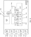
- FIG. 10 illustrates interfaces of baseband circuitry in accordance with an example
- FIG. 11 illustrates a diagram of a wireless device (e.g., UE) in accordance with an example.
- a wireless device e.g., UE
- UE User Equipment
- UE refers to a computing device capable of wireless digital communication such as a smart phone, a tablet computing device, a laptop computer, a multimedia device such as an iPod Touch®, or other type computing device that provides text or voice communication.
- the term “User Equipment (UE)” may also be referred to as a “mobile device,” “wireless device,” of “wireless mobile device.”
- Base Station includes “Base Transceiver Stations (BTS),” “NodeBs,” “evolved NodeBs (eNodeB or eNB),” and/or “next generation NodeBs (gNodeB or gNB),” and refers to a device or configured node of a mobile phone network that communicates wirelessly with UEs.
- BTS Base Transceiver Stations
- NodeBs nodeBs
- gNodeB or gNB next generation NodeBs
- cellular telephone network As used herein, the term “cellular telephone network,” “4G cellular,” “Long Term Evolved (LTE),” “5G cellular” and/or “New Radio (NR)” refers to wireless broadband technology developed by the Third Generation Partnership Project (3GPP).
- 3GPP Third Generation Partnership Project
- PBCH Physical Broadcast Channel
- DMRS Modulation Reference Signal
- NR New Radio
- transmit power boosting of reference signals can be used in cellular communication systems.
- the transmit power of RS can be boosted to improve a performance of channel estimation or RS detection at a UE.
- a transmitting base station such as a gNB in a New Radio (NR) system.
- the transmitting base station can signal to a UE regarding specific power boosting that is applied in the NR system to demodulation reference signals (DMRS) of a physical broadcast channel (PBCH).
- DMRS demodulation reference signals
- PBCH physical broadcast channel
- this power boosting can be known as a power offset between a PBCH-DMRS and NR-PBCH data resource elements (REs).
- a fixed power offset was used between the PBCH-DMRS and the NR-PBCH data REs, e.g., 0 decibels (dB).
- a variable power offset was used between the PBCH-DMRS and the NR-PBCH data REs, but the variable offset was not indicated to the UE.
- a variable power offset was selected from a set of possible set of values, but the variable offset was not indicated to the UE.
- knowledge about the power offset can be beneficial to advanced receivers (e.g., at the UE) having a PBCH interference cancellation capability.
- advanced receivers are typically not used for PBCH processing at the UE.
- the network can still apply power boosting, e.g., to implicitly improve PBCH-DMRS detection and/or the UE's channel estimation performance.
- the second option may be preferable due to the lack of limitations placed on the gNB, but the second option implies increased signal processing at the UE's advanced receiver in order to estimate an unknown power boosting value, and may not be preferable from the UE perspective. In other words, from the UE perspective, reducing complexity of receive signal processing is desirable.
- the third option can assume application of power offsets from a limited set of values predefined in the NR specification, but this reduction in complexity is only partial as multiple blind hypothesis testing would still be performed at the UE's advanced receiver.
- a fourth option can be used, in which a variable power offset between the PBCH-DMRS and the NR-PBCH data REs can be selected from a set of possible values (e.g., at most four values), and the variable power offset can be indicated to the UE in the NR-PBCH.
- This fourth option can be a compromise between flexibility for the network and complexity of UE implementation.
- the network can still select the variable power offset from a limited set of predefined values to boost PBCH-DMRS signals.
- the UE does not have to perform power offset estimation since the boosting value (i.e., the variable power offset) can be signaled from the gNB to the UE in the NR-PBCH.
- the signaling of the variable power offset in the NR-PBCH can be efficient since the UE already decodes a strong cell's PBCH for further reconstruction and subtraction to perform PBCH interference cancellation.
- the set of predefined power boosting values can be limited, so a relatively small number of bits can be used to encode the variable power offset (e.g., 2 bits).
- a UE can read the NR-PBCH of a target cell, which can be different than a serving cell that is associated with the UE.
- the serving cell can be a stronger cell as compared to the target cell, and interference from the serving cell's NR-PBCH transmission can affect an ability of the UE to successfully decode and read the target cell's NR-PBCH.
- the UE can apply advanced receiving techniques with PBCH interference cancellation.
- FIG. 1 illustrates an example of an advanced receiver 100 with a physical broadcast channel (PBCH) interference cancellation capability.
- the advanced receiver 100 can be included, for example, in a UE.
- the advanced receiver 100 can include a signal subtractor 102 , a channel estimator 104 , an NR-PBCH decoder 106 and a signal reconstructor 108 .
- the advanced receiver 100 can receive a signal, and the received signal can be sent to the channel estimator 104 .
- the channel estimator 104 can send channel estimates for a serving cell and a target cell to the NR-PBCH decoder 106 .
- the NR-PBCH decoder 106 can send a decoded serving cell's NR-PBCH to the signal reconstructor 108 .
- the channel estimates for the serving cell can also be sent to the signal reconstructor 108 .
- the signal reconstructor 108 can send a reconstructed serving cell's NR-PBCH to the signal subtractor 102 .
- the signal subtractor 102 can send a remaining signal after NR-PBCH cancellation to the channel estimator 104 , and then the NR-PBCH decoder 106 can output a decoded target cell's NR-PBCH.
- the UE can reconstruct the NR-PBCH transmitted from a wireless propagation channel and subtract the transmitted NR-PBCH from the received signal.
- the rest of the signal after subtraction can contain the target cell's NR-PBCH and a small portion of remaining interference plus noise.
- the serving cell's NR-PBCH signal reconstruction can include multiplication of an estimated channel transfer function (CTF) on NR-PBCH REs by a known modulated serving cell's NR-PBCH.
- CTF channel transfer function
- the estimation of the CTF itself can be based on the PBCH-DMRS.
- the power offset can be transmitted as part of an NR-PBCH payload, and therefore, can be used by the UE for de-boosting CTF estimates prior to multiplication with the known NR-PBCH.
- correct interfering signal reconstruction and successful cancellation can be achieved at the UE without using blind estimation techniques for power boosting.
- variable power offset signaled in the NR-PBCH from the gNB to the UE can be selected from a limited set of predefined values, which can be useful in restricting a number of bits used to encode the variable power offset value, e.g., 2 bits results in a set of 4 different possible variable power offsets.
- FIG. 2 illustrates an exemplary signal processing flow at an advanced receiver of a UE for receiving (e.g., decoding and reading) a target cell's NR-PBCH.
- the UE can perform a channel estimation using a serving cell's PBCH-DMRS.
- the UE can decode the serving cell's NR-PBCH.
- the UE can read a power offset (i.e., the variable power offset) between the PBCH-DMRS and NR-PBCH REs based on the serving cell's NR-PBCH.
- the UE can reconstruct a modulated serving cell's NR-PBCH using the variable power offset.
- the UE can subtract the reconstructed serving cell's NR-PBCH from a received signal.
- the UE can perform a channel estimation using a target cell's PBCH-DMRS.
- the UE can decode the target cell's NR-PBCH.
- a technique for power boosting of a PBCH-DMRS, in which an actual power offset value between the PBCH-DMRS and NR-PBCH data REs is signaled from a gNB to a UE as part of a payload of the NR-PBCH.
- the power offset value can be selected from a limited set of values predefined in an NR specification.
- a transport block size (TBS) design can involve a transport block size determination for an NR system.
- TBS design for flexible transport block size determination can be based on a hybrid approach of matching a transport block size to a scheduled resource and spectral efficiency, and also allowing an overhead invariant TBS determination.
- the transport block size can be implicitly indicated in downlink control information (DCI) via a combination of a modulation and coding scheme (MCS) index and resource allocation, and a scaling factor (e.g., a downlink pilot timeslot (DwPTS)).
- DCI downlink control information
- MCS modulation and coding scheme
- DwPTS downlink pilot timeslot
- the indication of the transport block size can be performed via a lookup table, specified in 3GPP Technical Specification (TS) 36.213, whose entries are determined using a fixed overhead assumption on available resource elements (REs) per resource block, etc.
- TS Technical Specification
- Some adjustments to TBS determination are also applied when necessitated in the LTE system, including a special handling of combinations that can affect peak data rate.
- an MCS indication in the NR system can be similar to that of the LTE system.
- the MCS indication in the NR system can indicate a nominal (or intended) spectral efficiency and a modulation order. Then, based on allocated resources, a UE can determine an available number of REs, and then determine a byte-aligned TBS according to the following expression:
- TBS 8 ⁇ ⁇ Q m ⁇ R ⁇ N RE ⁇ N L 8 ⁇ , wherein Q m denotes a scheduled modulation order, R denotes an intended code rate, N RE denotes a number of resource elements in the resource allocation on which data can be transmitted, and N L denotes a number of layers to which the TBS is mapped.
- R ⁇ Qm can denote a spectral efficiency, and N RE can be determined from allocated resources and removing overhead.
- the overhead(s) that are to be taken into account can include one or more of a demodulation reference signal (DMRS), a sounding reference signal (SRS), guard periods or symbols indicated as “Unknown” via slot format information (SFI), possible physical downlink control channel (PDCCH), secondary synchronization signal (SSS), primary synchronization signal (PSS), physical broadcast channel (PBCH), channel state information reference signal (CSI-RS), and any other overhead explicitly indicated to the UE.
- DMRS density itself can be variable depending upon a possible configuration (e.g., front-loaded vs front/back DMRS, different number of antenna ports, presence/absence of tracking reference signal (TRS), etc.).
- the approach described above for the calculation of TBS with respect to NR is different than a TBS calculation approach in LTE.
- a “table-based” approach can be used, in contrast to the NR approach of using a hybrid of a table-based approach (for small TB sizes) and a formula-based approach otherwise.
- the UE can use a signaled MCS index to determine a TBS index (I_TBS), and then the UE can use a number of PRB pairs scheduled to look up the TBS value from a table specified in 3GPP TS 36.213.
- the UE can count/approximate the number of REs (a reference number of REs), and uses the formula of to
- TBS 8 ⁇ ⁇ Q m ⁇ R ⁇ N RE ⁇ N L 8 ⁇ determine an intermediate TBS value, which can be further quantized to determine a final TBS value.
- a PRB implies 12 subcarriers by 1 symbol, and thus comprises of 12 REs, which is different from LTE.
- the UE can determine the reference number of REs.
- the above expression can be used to indicate the TBS on a first transmission to the UE.
- at least three mechanisms are feasible.
- the gNB can arrange an exact same size allocation (e.g., yielding N RE ) to the UE, which can be feasible for the gNB, but may place some scheduling restrictions, e.g., in cases where the gNB is dynamically varying a slot format.
- the gNB can rely on an implicit TBS indication (similar to MCS 29, 30, 31 in LTE).
- This kind of implicit method for TBS determination can also be used for the case of code block group (CBG)-based transmissions.
- the TBS in addition to the two mechanisms described above, the TBS can be derived using a reference formula which allows the gNB to indicate the TBS, which can be somewhat invariant to overhead. For further flexibility, different overheads can be supported.
- TBS indication all of the three mechanisms described above can be considered for TBS indication.
- a two-bit TBS indicator can be introduced in the DCI to provide the desired flexibility e.g., for slot based indication, the resource allocation can be used in conjunction with the following table.
- the TBS determination mechanism can be independently configured for DCI scheduled via different core-sets.
- a common corset can apply a TBS determination based on a first set of assumptions of reference overhead
- UE-specific core-set 1 can apply a second TBS determination based on a second set of assumptions of reference overhead, and so on.
- TBS 8 ⁇ ⁇ Q m ⁇ R ⁇ N RB ⁇ 120 ⁇ ( l / 12 ) ⁇ N L 8 ⁇
- the TBS can be calculated by determining an exact number of REs in the resources allocated, and using the formula mentioned earlier (based on N RE ).
- one reference TBS table can be constructed from the MCS (i.e., Q m and R) and a number of data layers (i.e., N L ), while assuming a fixed overhead (e.g., symbols in time domain or REs in time/frequency in one PRB) for control, reference signal and other signals.
- This single reference MCS table used for TBS determination can be invariant to the signaling overhead due to varied antenna ports (including both DMRS and CSI-RS), the number of CORESETS, the presence of SRS, SS/PBCH blocks and varied slot format, etc.
- one or more adjustment factors can be provided to account for the variable REs due to the absence or presence of CORSETS region and/or CSI-RS/DMRS, and/or SS/PBCH blocks, etc.
- the adjustment factors can at least have a value smaller than 1 to account for the puncturing of other signals.
- the adjustment factors can also include at least one value greater than 1 to account for the increased number of REs due to slot aggregation or multiple scheduling, and with the assumption that the reference MCS table can be defined based on a single slot transmission.
- more than one adjustment factor can be defined and fixed in the NR specification. For example, different adjustment factors can be defined based on the number of ranks for data transmission.
- one adjustment factor can be provided for a DL-only or UL-only slot and one or more adjustment factors can be provided for a hybrid slot consisting of both a DL and UL part in one slot. The adjustment factors can be different for DL and UL due to the different slot structure.
- one adjustment factor can be provided for the slot containing a SS/PBCH block and one or more adjustment factors can be provided for slots without a SS/PBCH.
- multiple adjustment factors can be defined and one of the adjustment factors can be signaled to the UE using a DCI format.
- the adjustment factor can be determined by the UE based on a number of data symbols and the presence of other signals (e.g., slot format, DMRS/CSI-RS configuration, PBCH/SS-block) that are pre-known by UE.
- the reference overheads via scaling may not be sufficient in reflecting the true overheads, and in such cases, a higher layer configuration can be used to define an additional table as follows (e.g., assuming 2-symbol mini-slot and 1/3 DMRS of 1 OFDM symbol).
- an explicit TBS table can be designed for a certain combination of MCS and resource allocation (RA) combinations (e.g., up to MCS 2 bits per second (bps) and a RA of up to 4 PRBs).
- RA resource allocation
- the TBS can be defined for smaller packet sizes, and the TBS can be selected from a set for up to a particular threshold TB size. For example, when an intermediate number of information bits is less than a particular threshold value, TBS values can be selected based on a specified set of values of smaller TB sizes (i.e., a look up table approach).
- another approach for TBS determination can involve defining a TBS grid at least beyond a certain length (e.g., greater than a maximum code block size of 8448), and rounding a calculated number (from formula) to a nearest value in the TBS grid, which can reduce a total number of transport block sizes to be supported, as well as ensure that frequently encountered payloads are prioritized.
- a “nearest” TBS size determination can be performed using a round operation, ceiling operation, flooring operation or a similar operation.
- the TBS grid can be defined such that code block segmentation with equal and byte-aligned code block sizes can be supported.
- the code block sizes can be explicitly defined in the specification, and the TBS grid can be defined to include transport block sizes that satisfy equal sized code blocks.
- the TBS grid can include values such that after code block segmentation (and TB and cyclic redundancy check (CRC) attachment), a single code block size belonging to a defined code block size set can be yielded, which can enable a low-density parity-check (LDPC) decoder to be optimized for a small set of input sizes.
- CRC cyclic redundancy check
- a transport block in slot aggregation, can be mapped to multiple slots, which can be analogous to a transmission time interval (TTI) bundling operation in an LTE system.
- TTI transmission time interval
- the transport block size can be determined based on a single slot allocation, and the other slots can effectively be retransmissions of the same TB.
- the entire aggregated slots can be considered to determine the TBS (similar to a coverage enhancement use case), but for medium to high MCS, such configurations leading to large TBS (due to slot aggregation) are to be avoided. as they can cause undue burden to the UE.
- BPSK binary phase shift keying
- a TBS determination assuming mapping to aggregated slots or aggregation of slots and symbols can be subject to certain limits on the MCS and/or frequency domain resource allocation, such that the TBS is not simply scaled up with the number of aggregated slots for the highest possible spectral efficiency.
- some exceptions can be considered to align the maximum TBS supported across different numerologies, while considering differences in the maximum supported allocation bandwidth for different subcarrier spacing (SCS) choices.
- a maximum channel bandwidth (BW) for a SCS of 15 kilohertz (kHz) can be 50 Megahertz (MHz), and for 30 kHz and 60 kHz options, the maximum channel BW can be 100 MHz, while for a SCS of 120 kHz, the maximum channel BW can be 400 MHz.
- the maximum TBS can be derived under the assumptions of highest spectral efficiency and maximum allocated bandwidth for TB mapped to an aggregation of up to two slots.
- the maximum TBS can be derived under the assumptions of highest spectral efficiency and maximum allocated bandwidth for TB mapped to an aggregation of up to two slots. Further, such aggregated slot-based max TBS determination can be only applicable for sub-6 GHz carrier frequencies.
- a data channel coding scheme used in an NR system is LDPC, and two base graphs (BG1 and BG2) can be used, each supporting a different range of native code rates and block sizes.
- BG1 covers rates ⁇ 8/9 to ⁇ 1/3, and BG2 covers ⁇ 2/3 to ⁇ 1/5, and BG1 covers information block between ⁇ 512 to 8448, and BG2 covers information block sizes between 40 and 2560.
- an appropriate base graph for encoding the given transport block size can be selected accordingly.
- BG2 can be used for transport block sizes less than or equal to 2560 and an initial transmission code rate less than or equal to 2/3.
- a “rate” can be defined in various manners, e.g., rate can be a nominal rate indicated by the MCS (R ⁇ Qm), or the rate can be calculated based on the determined transport block size using the following equation:
- whether the UE uses a nominal or calculated code rate can be jointly coded into 2-bits that include the TBS calculation mechanism. Since the mathematical expressions could create some ambiguity, especially if the rate indicated in the MCS is not quantized properly, for such cases, the rate definition can follow a 10-bit precision explicitly specified in the specification as part of the MCS definition. In addition, in certain cases, the network can explicitly configure some limits on BG2 usage, based on a restricted subset of MCS levels and/or resource allocation in time and resource allocation in frequency domain.
- the values of Qm can belong to ⁇ 1,2,4,6,8,10, etc. ⁇ which correspond to the modulation order, and the number of layers can be ⁇ 1,2,3,4, etc. ⁇
- n can be a power of two (e.g., 1024), which can allow for a straightforward implementation for TBS determination.
- code block segmentation there can be restrictions from the code block segmentation that may also be used to determine the appropriate TBS value.
- CB code block
- TB transport block
- TBS+(C+1)*L CRC C*K CB , wherein L CRC is a CRC length for TB-level and CB-level, K CB is the CB size, and C is a number of code block segments.
- FIG. 3 illustrates an example of a plurality of code block segments (C).
- the code block segments can include transport block (TB) cyclic redundancy checks (CRC) and code block (CB) CRC.
- a CB size (K CB ) of the code block segments can include the TB-CRC and the CB-CRC.
- a LDPC size (K LDPC ) of the code block segments can include the TB-CRC, the CB-CRC and filler.
- the LDPC size (K LDPC ) can include the CB size (K CB ) in addition to the filter.
- an actual number of REs (G) can be determined from assigned resources, which can be determined based on a number of PRBs, a number of time-domain allocation, a DMRS assigned in the slot, possible CSI-RS, possible SRS, etc. Then the UE can determine a reference number of REs (H) by quantizing the actual number of REs (G), based on one or more of physical layer signaling, MAC or higher layer signaling (RRC), or a pre-determined rule in the specification.
- RRC higher layer signaling
- the set itself can be determined from one or more sets indicated by higher layer and/or physical layer signaling. For example, multiple sets can be defined by higher layers, and the physical layer DCI can indicate explicitly or implicitly the set to apply for a particular TB. Then, the TBS can be determined by finding the closest match to the formula, as described previously.
- FIG. 4 is an example of a table of values for numbers of resource elements (NREs) based on different values of NREs per physical resource block (PRB) (or NREs/PRB) and a number of PRBs (NRBs).
- the TBS determination can further include determining a reference number of PRBs from an indicated set of resources (G) and a reference number of REs (e.g., indicated in DCI (120)).
- the reference number of REs/PRB can be indicated in the DCI, and can be determined from one or more sets indicated by higher layer and/or physical layer signaling. For example, multiple sets can be defined by higher layers, and the physical layer DCI can indicate explicitly or implicitly the set to apply for a particular TB.
- a technique for determining a transport block size can be defined.
- the technique can involve acquiring information regarding a first number of assigned resource elements (REs) for a transport block in one or more symbols based on one or more of downlink control information and higher layer signaling.
- the technique can involve determining a reference number of REs per physical resource block (PRB) based on the first number of assigned REs, and at least a reference number of PRBs for the transport block.
- PRB physical resource block
- the technique can involve determining a transport block size based on at least the reference number of REs per PRB and the reference number of PRBs.
- the technique can involve transmitting a transport block in accordance with the determined transport block size.
- the transport block size can yield a single code block size for all code blocks of a TBS, when code block segmentation is applied to the TBS.
- the single code block size can be a multiple of 8, where a CRC can be attached for the transport block and code block during code block segmentation.
- a reference number of PRBs can be equal to a number of PRBs assigned in the control information, the reference number of PRBs can be not equal to the number of PRBs assigned in the control information, or the reference number of PRBs can be smaller than or larger than the number of PRBs assigned in the control information.
- all transport block sizes can be derived such that the code block size for each transport block is a multiple of 8, where a CRC can be attached for the transport block and code block during code block segmentation.
- the UE can comprise one or more processors configured to determine, at the UE, a number of assigned resource elements (REs) in one or more symbols for a transport block, as in block 510 .
- the UE can comprise one or more processors configured to determine, at the UE, a reference number of REs per physical resource block (PRB) in the transport block based on a reference number of REs for the transport block corresponding to each PRB and an assigned number of PRBs for the transport block, as in block 520 .
- PRB physical resource block
- the UE can comprise one or more processors configured to determine, at the UE, a TBS for the transport block based at least on the reference number of REs per PRB in the transport block, a scheduled modulation order, an intended code rate and a number of layers mapped to the TBS, as in block 530 .
- the UE can comprise one or more processors configured to encode, at the UE, information in a selected transport block for transmission via a physical uplink shared channel (PUSCH) to a Next Generation NodeB (gNB) in accordance with the TBS determined at the UE, as in block 540 .
- PUSCH physical uplink shared channel
- gNB Next Generation NodeB
- the UE can comprise one or more processors configured to decode, at the UE, information in a selected transport block received from the gNB via a physical downlink shared channel (PDSCH) in accordance with the TBS determined at the UE, as in block 550 .
- the UE can comprise a memory interface configured to send to a memory an indication of the TBS.
- the UE can comprise one or more processors configured to decode, at the UE, the variable power offset received from the gNB that indicates a power level of power boosting applied by the gNB to a demodulation reference signal in a physical broadcast channel (DMRS-PBCH) relative to New Radio PBCH (NR-PBCH) resource elements (REs), as in block 610 .
- the UE can comprise one or more processors configured to detect, at the UE, a reference signal (RS) in the NR-PBCH based in part on the variable power offset received from the gNB, as in block 620 .
- the UE can comprise a memory interface configured to send to a memory an indication of the variable power offset.
- Another example provides at least one machine readable storage medium having instructions 700 embodied thereon for determining a transport block size (TBS) at a user equipment (UE), as shown in FIG. 7 .
- the instructions can be executed on a machine, where the instructions are included on at least one computer readable medium or one non-transitory machine readable storage medium.
- the instructions when executed by one or more processors of the UE perform: determining, at the UE, a number of assigned resource elements (REs) in one or more symbols for a transport block, as in block 710 .
- REs resource elements
- the instructions when executed by one or more processors of the UE perform: determining, at the UE, a reference number of REs per physical resource block (PRB) in the transport block based on a reference number of REs for the transport block corresponding to each PRB and an assigned number of PRBs for the transport block, as in block 720 .
- the instructions when executed by one or more processors of the UE perform: determining, at the UE, a TBS for the transport block based at least on the reference number of REs per PRB in the transport block, a scheduled modulation order, an intended code rate and a number of layers mapped to the TBS, as in block 730 .
- PRB physical resource block
- the instructions when executed by one or more processors of the UE perform: encoding, at the UE, information in a selected transport block for transmission via a physical uplink shared channel (PUSCH) to a Next Generation NodeB (gNB) in accordance with the TBS determined at the UE, as in block 740 .
- the instructions when executed by one or more processors of the UE perform: decoding, at the UE, information in a selected transport block received from the gNB via a physical downlink shared channel (PDSCH) in accordance with the TBS determined at the UE, as in block 750 .
- PUSCH physical uplink shared channel
- gNB Next Generation NodeB
- FIG. 8 illustrates an architecture of a system 800 of a network in accordance with some embodiments.
- the system 800 is shown to include a user equipment (UE) 801 and a UE 802 .
- the UEs 801 and 802 are illustrated as smartphones (e.g., handheld touchscreen mobile computing devices connectable to one or more cellular networks), but may also comprise any mobile or non-mobile computing device, such as Personal Data Assistants (PDAs), pagers, laptop computers, desktop computers, wireless handsets, or any computing device including a wireless communications interface.
- PDAs Personal Data Assistants
- pagers pagers
- laptop computers desktop computers
- wireless handsets or any computing device including a wireless communications interface.
- any of the UEs 801 and 802 can comprise an Internet of Things (IoT) UE, which can comprise a network access layer designed for low-power IoT applications utilizing short-lived UE connections.
- An IoT UE can utilize technologies such as machine-to-machine (M2M) or machine-type communications (MTC) for exchanging data with an MTC server or device via a public land mobile network (PLMN), Proximity-Based Service (ProSe) or device-to-device (D2D) communication, sensor networks, or IoT networks.
- M2M or MTC exchange of data may be a machine-initiated exchange of data.
- An IoT network describes interconnecting IoT UEs, which may include uniquely identifiable embedded computing devices (within the Internet infrastructure), with short-lived connections.
- the IoT UEs may execute background applications (e.g., keep-alive messages, status updates, etc.) to facilitate the connections of the IoT network.
- the UEs 801 and 802 may be configured to connect, e.g., communicatively couple, with a radio access network (RAN) 810 —the RAN 810 may be, for example, an Evolved Universal Mobile Telecommunications System (UMTS) Terrestrial Radio Access Network (E-UTRAN), a NextGen RAN (NG RAN), or some other type of RAN.
- RAN radio access network
- UMTS Evolved Universal Mobile Telecommunications System
- E-UTRAN Evolved Universal Mobile Telecommunications System
- NG RAN NextGen RAN
- the UEs 801 and 802 utilize connections 803 and 804 , respectively, each of which comprises a physical communications interface or layer (discussed in further detail below); in this example, the connections 803 and 804 are illustrated as an air interface to enable communicative coupling, and can be consistent with cellular communications protocols, such as a Global System for Mobile Communications (GSM) protocol, a code-division multiple access (CDMA) network protocol, a Push-to-Talk (PTT) protocol, a PTT over Cellular (POC) protocol, a Universal Mobile Telecommunications System (UMTS) protocol, a 3GPP Long Term Evolution (LTE) protocol, a fifth generation (5G) protocol, a New Radio (NR) protocol, and the like.
- GSM Global System for Mobile Communications
- CDMA code-division multiple access
- PTT Push-to-Talk
- POC PTT over Cellular
- UMTS Universal Mobile Telecommunications System
- LTE Long Term Evolution
- 5G fifth generation
- NR New Radio
- the UEs 801 and 802 may further directly exchange communication data via a ProSe interface 805 .
- the ProSe interface 805 may alternatively be referred to as a sidelink interface comprising one or more logical channels, including but not limited to a Physical Sidelink Control Channel (PSCCH), a Physical Sidelink Shared Channel (PSSCH), a Physical Sidelink Discovery Channel (PSDCH), and a Physical Sidelink Broadcast Channel (PSBCH).
- PSCCH Physical Sidelink Control Channel
- PSSCH Physical Sidelink Shared Channel
- PSDCH Physical Sidelink Discovery Channel
- PSBCH Physical Sidelink Broadcast Channel
- the UE 802 is shown to be configured to access an access point (AP) 806 via connection 807 .
- the connection 807 can comprise a local wireless connection, such as a connection consistent with any IEEE 902.15 protocol, wherein the AP 806 would comprise a wireless fidelity (WiFi®) router.
- WiFi® wireless fidelity
- the AP 806 is shown to be connected to the Internet without connecting to the core network of the wireless system (described in further detail below).
- the RAN 810 can include one or more access nodes that enable the connections 803 and 804 .
- These access nodes can be referred to as base stations (BSs), NodeBs, evolved NodeBs (eNBs), next Generation NodeBs (gNB), RAN nodes, and so forth, and can comprise ground stations (e.g., terrestrial access points) or satellite stations providing coverage within a geographic area (e.g., a cell).
- BSs base stations
- eNBs evolved NodeBs
- gNB next Generation NodeBs
- RAN nodes and so forth, and can comprise ground stations (e.g., terrestrial access points) or satellite stations providing coverage within a geographic area (e.g., a cell).
- the RAN 810 may include one or more RAN nodes for providing macrocells, e.g., macro RAN node 811 , and one or more RAN nodes for providing femtocells or picocells (e.g., cells having smaller coverage areas, smaller user capacity, or higher bandwidth compared to macrocells), e.g., low power (LP) RAN node 812 .
- macro RAN node 811 e.g., macro RAN node 811
- femtocells or picocells e.g., cells having smaller coverage areas, smaller user capacity, or higher bandwidth compared to macrocells
- LP low power
- any of the RAN nodes 811 and 812 can terminate the air interface protocol and can be the first point of contact for the UEs 801 and 802 .
- any of the RAN nodes 811 and 812 can fulfill various logical functions for the RAN 810 including, but not limited to, radio network controller (RNC) functions such as radio bearer management, uplink and downlink dynamic radio resource management and data packet scheduling, and mobility management.
- RNC radio network controller
- the UEs 801 and 802 can be configured to communicate using Orthogonal Frequency-Division Multiplexing (OFDM) communication signals with each other or with any of the RAN nodes 811 and 812 over a multicarrier communication channel in accordance various communication techniques, such as, but not limited to, an Orthogonal Frequency-Division Multiple Access (OFDMA) communication technique (e.g., for downlink communications) or a Single Carrier Frequency Division Multiple Access (SC-FDMA) communication technique (e.g., for uplink and ProSe or sidelink communications), although the scope of the embodiments is not limited in this respect.
- OFDM signals can comprise a plurality of orthogonal subcarriers.
- a downlink resource grid can be used for downlink transmissions from any of the RAN nodes 811 and 812 to the UEs 801 and 802 , while uplink transmissions can utilize similar techniques.
- the grid can be a time-frequency grid, called a resource grid or time-frequency resource grid, which is the physical resource in the downlink in each slot.
- a time-frequency plane representation is a common practice for OFDM systems, which makes it intuitive for radio resource allocation.
- Each column and each row of the resource grid corresponds to one OFDM symbol and one OFDM subcarrier, respectively.
- the duration of the resource grid in the time domain corresponds to one slot in a radio frame.
- the smallest time-frequency unit in a resource grid is denoted as a resource element.
- Each resource grid comprises a number of resource blocks, which describe the mapping of certain physical channels to resource elements.
- Each resource block comprises a collection of resource elements; in the frequency domain, this may represent the smallest quantity of resources that currently can be allocated.
- the physical downlink shared channel may carry user data and higher-layer signaling to the UEs 801 and 802 .
- the physical downlink control channel (PDCCH) may carry information about the transport format and resource allocations related to the PDSCH channel, among other things. It may also inform the UEs 801 and 802 about the transport format, resource allocation, and H-ARQ (Hybrid Automatic Repeat Request) information related to the uplink shared channel.
- downlink scheduling (assigning control and shared channel resource blocks to the UE 802 within a cell) may be performed at any of the RAN nodes 811 and 812 based on channel quality information fed back from any of the UEs 801 and 802 .
- the downlink resource assignment information may be sent on the PDCCH used for (e.g., assigned to) each of the UEs 801 and 802 .
- the PDCCH may use control channel elements (CCEs) to convey the control information.
- CCEs control channel elements
- the PDCCH complex-valued symbols may first be organized into quadruplets, which may then be permuted using a sub-block interleaver for rate matching.
- Each PDCCH may be transmitted using one or more of these CCEs, where each CCE may correspond to nine sets of four physical resource elements known as resource element groups (REGs).
- RAGs resource element groups
- QPSK Quadrature Phase Shift Keying
- the PDCCH can be transmitted using one or more CCEs, depending on the size of the downlink control information (DCI) and the channel condition.
- DCI downlink control information
- There can be four or more different PDCCH formats defined in LTE with different numbers of CCEs (e.g., aggregation level, L 1, 2, 4, or 9).
- Some embodiments may use concepts for resource allocation for control channel information that are an extension of the above-described concepts.
- some embodiments may utilize an enhanced physical downlink control channel (EPDCCH) that uses PDSCH resources for control information transmission.
- the EPDCCH may be transmitted using one or more enhanced the control channel elements (ECCEs). Similar to above, each ECCE may correspond to nine sets of four physical resource elements known as an enhanced resource element groups (EREGs). An ECCE may have other numbers of EREGs in some situations.
- EPCCH enhanced physical downlink control channel
- ECCEs enhanced the control channel elements
- each ECCE may correspond to nine sets of four physical resource elements known as an enhanced resource element groups (EREGs).
- EREGs enhanced resource element groups
- An ECCE may have other numbers of EREGs in some situations.
- the RAN 810 is shown to be communicatively coupled to a core network (CN) 820 —via an S1 interface 813 .
- the CN 820 may be an evolved packet core (EPC) network, a NextGen Packet Core (NPC) network, or some other type of CN.
- EPC evolved packet core
- NPC NextGen Packet Core
- the S1 interface 813 is split into two parts: the S1-U interface 814 , which carries traffic data between the RAN nodes 811 and 812 and the serving gateway (S-GW) 822 , and the S1-mobility management entity (MME) interface 815 , which is a signaling interface between the RAN nodes 811 and 812 and MMEs 821 .
- MME S1-mobility management entity
- the CN 820 comprises the MMEs 821 , the S-GW 822 , the Packet Data Network (PDN) Gateway (P-GW) 823 , and a home subscriber server (HSS) 824 .
- the MMEs 821 may be similar in function to the control plane of legacy Serving General Packet Radio Service (GPRS) Support Nodes (SGSN).
- the MMEs 821 may manage mobility aspects in access such as gateway selection and tracking area list management.
- the HSS 824 may comprise a database for network users, including subscription-related information to support the network entities' handling of communication sessions.
- the CN 820 may comprise one or several HSSs 824 , depending on the number of mobile subscribers, on the capacity of the equipment, on the organization of the network, etc.
- the HSS 824 can provide support for routing/roaming, authentication, authorization, naming/addressing resolution, location dependencies, etc.
- the S-GW 822 may terminate the S1 interface 813 towards the RAN 810 , and routes data packets between the RAN 810 and the CN 820 .
- the S-GW 822 may be a local mobility anchor point for inter-RAN node handovers and also may provide an anchor for inter-3GPP mobility. Other responsibilities may include lawful intercept, charging, and some policy enforcement.
- the P-GW 823 may terminate an SGi interface toward a PDN.
- the P-GW 823 may route data packets between the EPC network 823 and external networks such as a network including the application server 830 (alternatively referred to as application function (AF)) via an Internet Protocol (IP) interface 825 .
- the application server 830 may be an element offering applications that use IP bearer resources with the core network (e.g., UMTS Packet Services (PS) domain, LTE PS data services, etc.).
- PS UMTS Packet Services
- LTE PS data services etc.
- the P-GW 823 is shown to be communicatively coupled to an application server 830 via an IP communications interface 825 .
- the application server 830 can also be configured to support one or more communication services (e.g., Voice-over-Internet Protocol (VoIP) sessions, PTT sessions, group communication sessions, social networking services, etc.) for the UEs 801 and 802 via the CN 820 .
- VoIP Voice-over-Internet Protocol
- PTT sessions PTT sessions
- group communication sessions social networking services, etc.
- the P-GW 823 may further be a node for policy enforcement and charging data collection.
- Policy and Charging Enforcement Function (PCRF) 826 is the policy and charging control element of the CN 820 .
- PCRF Policy and Charging Enforcement Function
- HPLMN Home Public Land Mobile Network
- IP-CAN Internet Protocol Connectivity Access Network
- HPLMN Home Public Land Mobile Network
- V-PCRF Visited PCRF
- VPLMN Visited Public Land Mobile Network
- the PCRF 826 may be communicatively coupled to the application server 830 via the P-GW 823 .
- the application server 830 may signal the PCRF 826 to indicate a new service flow and select the appropriate Quality of Service (QoS) and charging parameters.
- the PCRF 826 may provision this rule into a Policy and Charging Enforcement Function (PCEF) (not shown) with the appropriate traffic flow template (TFT) and QoS class of identifier (QCI), which commences the QoS and charging as specified by the application server 830 .
- PCEF Policy and Charging Enforcement Function
- TFT traffic flow template
- QCI QoS class of identifier
- FIG. 9 illustrates example components of a device 900 in accordance with some embodiments.
- the device 900 may include application circuitry 902 , baseband circuitry 904 , Radio Frequency (RF) circuitry 906 , front-end module (FEM) circuitry 908 , one or more antennas 910 , and power management circuitry (PMC) 912 coupled together at least as shown.
- the components of the illustrated device 900 may be included in a UE or a RAN node.
- the device 900 may include less elements (e.g., a RAN node may not utilize application circuitry 902 , and instead include a processor/controller to process IP data received from an EPC).
- the device 900 may include additional elements such as, for example, memory/storage, display, camera, sensor, or input/output (I/O) interface.
- additional elements such as, for example, memory/storage, display, camera, sensor, or input/output (I/O) interface.
- the components described below may be included in more than one device (e.g., said circuitries may be separately included in more than one device for Cloud-RAN (C-RAN) implementations).
- C-RAN Cloud-RAN
- the application circuitry 902 may include one or more application processors.
- the application circuitry 902 may include circuitry such as, but not limited to, one or more single-core or multi-core processors.
- the processor(s) may include any combination of general-purpose processors and dedicated processors (e.g., graphics processors, application processors, etc.).
- the processors may be coupled with or may include memory/storage and may be configured to execute instructions stored in the memory/storage to enable various applications or operating systems to run on the device 900 .
- processors of application circuitry 902 may process IP data packets received from an EPC.
- the baseband circuitry 904 may include circuitry such as, but not limited to, one or more single-core or multi-core processors.
- the baseband circuitry 904 may include one or more baseband processors or control logic to process baseband signals received from a receive signal path of the RF circuitry 906 and to generate baseband signals for a transmit signal path of the RF circuitry 906 .
- Baseband processing circuity 904 may interface with the application circuitry 902 for generation and processing of the baseband signals and for controlling operations of the RF circuitry 906 .
- the baseband circuitry 904 may include a third generation (3G) baseband processor 904 a , a fourth generation (4G) baseband processor 904 b , a fifth generation (5G) baseband processor 904 c , or other baseband processor(s) 904 d for other existing generations, generations in development or to be developed in the future (e.g., second generation (2G), sixth generation (6G), etc.).
- the baseband circuitry 904 (e.g., one or more of baseband processors 904 a - d ) may handle various radio control functions that enable communication with one or more radio networks via the RF circuitry 906 .
- baseband processors 904 a - d may be included in modules stored in the memory 904 g and executed via a Central Processing Unit (CPU) 904 e .
- the radio control functions may include, but are not limited to, signal modulation/demodulation, encoding/decoding, radio frequency shifting, etc.
- modulation/demodulation circuitry of the baseband circuitry 904 may include Fast-Fourier Transform (FFT), precoding, or constellation mapping/demapping functionality.
- FFT Fast-Fourier Transform
- the baseband circuitry 904 may include one or more audio digital signal processor(s) (DSP) 904 f .
- the audio DSP(s) 904 f may be include elements for compression/decompression and echo cancellation and may include other suitable processing elements in other embodiments.
- Components of the baseband circuitry may be suitably combined in a single chip, a single chipset, or disposed on a same circuit board in some embodiments.
- some or all of the constituent components of the baseband circuitry 904 and the application circuitry 902 may be implemented together such as, for example, on a system on a chip (SOC).
- SOC system on a chip
- the baseband circuitry 904 may provide for communication compatible with one or more radio technologies.
- the baseband circuitry 904 may support communication with an evolved universal terrestrial radio access network (EUTRAN) or other wireless metropolitan area networks (WMAN), a wireless local area network (WLAN), a wireless personal area network (WPAN).
- EUTRAN evolved universal terrestrial radio access network
- WMAN wireless metropolitan area networks
- WLAN wireless local area network
- WPAN wireless personal area network
- multi-mode baseband circuitry Embodiments in which the baseband circuitry 904 is configured to support radio communications of more than one wireless protocol.
- RF circuitry 906 may enable communication with wireless networks using modulated electromagnetic radiation through a non-solid medium.
- the RF circuitry 906 may include switches, filters, amplifiers, etc. to facilitate the communication with the wireless network.
- RF circuitry 906 may include a receive signal path which may include circuitry to down-convert RF signals received from the FEM circuitry 908 and provide baseband signals to the baseband circuitry 904 .
- RF circuitry 906 may also include a transmit signal path which may include circuitry to up-convert baseband signals provided by the baseband circuitry 904 and provide RF output signals to the FEM circuitry 908 for transmission.
- the amplifier circuitry 906 b may be configured to amplify the down-converted signals and the filter circuitry 906 c may be a low-pass filter (LPF) or band-pass filter (BPF) configured to remove unwanted signals from the down-converted signals to generate output baseband signals.
- Output baseband signals may be provided to the baseband circuitry 904 for further processing.
- the output baseband signals may be zero-frequency baseband signals, although this is not a necessity.
- mixer circuitry 906 a of the receive signal path may comprise passive mixers, although the scope of the embodiments is not limited in this respect.
- the mixer circuitry 906 a of the transmit signal path may be configured to up-convert input baseband signals based on the synthesized frequency provided by the synthesizer circuitry 906 d to generate RF output signals for the FEM circuitry 908 .
- the baseband signals may be provided by the baseband circuitry 904 and may be filtered by filter circuitry 906 c.
- the output baseband signals and the input baseband signals may be analog baseband signals, although the scope of the embodiments is not limited in this respect.
- the output baseband signals and the input baseband signals may be digital baseband signals.
- the RF circuitry 906 may include analog-to-digital converter (ADC) and digital-to-analog converter (DAC) circuitry and the baseband circuitry 904 may include a digital baseband interface to communicate with the RF circuitry 906 .
- ADC analog-to-digital converter
- DAC digital-to-analog converter
- a separate radio IC circuitry may be provided for processing signals for each spectrum, although the scope of the embodiments is not limited in this respect.
- the synthesizer circuitry 906 d may be a fractional-N synthesizer or a fractional N/N+1 synthesizer, although the scope of the embodiments is not limited in this respect as other types of frequency synthesizers may be suitable.
- synthesizer circuitry 906 d may be a delta-sigma synthesizer, a frequency multiplier, or a synthesizer comprising a phase-locked loop with a frequency divider.
- the synthesizer circuitry 906 d may be configured to synthesize an output frequency for use by the mixer circuitry 906 a of the RF circuitry 906 based on a frequency input and a divider control input. In some embodiments, the synthesizer circuitry 906 d may be a fractional N/N+1 synthesizer.
- frequency input may be provided by a voltage controlled oscillator (VCO), although that is not a necessity.
- VCO voltage controlled oscillator
- Divider control input may be provided by either the baseband circuitry 904 or the applications processor 902 depending on the desired output frequency.
- a divider control input (e.g., N) may be determined from a look-up table based on a channel indicated by the applications processor 902 .
- Synthesizer circuitry 906 d of the RF circuitry 906 may include a divider, a delay-locked loop (DLL), a multiplexer and a phase accumulator.
- the divider may be a dual modulus divider (DMD) and the phase accumulator may be a digital phase accumulator (DPA).
- the DMD may be configured to divide the input signal by either N or N+1 (e.g., based on a carry out) to provide a fractional division ratio.
- the DLL may include a set of cascaded, tunable, delay elements, a phase detector, a charge pump and a D-type flip-flop.
- the delay elements may be configured to break a VCO period up into Nd equal packets of phase, where Nd is the number of delay elements in the delay line.
- Nd is the number of delay elements in the delay line.
- synthesizer circuitry 906 d may be configured to generate a carrier frequency as the output frequency, while in other embodiments, the output frequency may be a multiple of the carrier frequency (e.g., twice the carrier frequency, four times the carrier frequency) and used in conjunction with quadrature generator and divider circuitry to generate multiple signals at the carrier frequency with multiple different phases with respect to each other.
- the output frequency may be a LO frequency (fLO).
- the RF circuitry 906 may include an IQ/polar converter.
- the FEM circuitry 908 may include a TX/RX switch to switch between transmit mode and receive mode operation.
- the FEM circuitry may include a receive signal path and a transmit signal path.
- the receive signal path of the FEM circuitry may include an LNA to amplify received RF signals and provide the amplified received RF signals as an output (e.g., to the RF circuitry 906 ).
- the transmit signal path of the FEM circuitry 908 may include a power amplifier (PA) to amplify input RF signals (e.g., provided by RF circuitry 906 ), and one or more filters to generate RF signals for subsequent transmission (e.g., by one or more of the one or more antennas 910 ).
- PA power amplifier
- the PMC 912 may manage power provided to the baseband circuitry 904 .
- the PMC 912 may control power-source selection, voltage scaling, battery charging, or DC-to-DC conversion.
- the PMC 912 may often be included when the device 900 is capable of being powered by a battery, for example, when the device is included in a UE.
- the PMC 912 may increase the power conversion efficiency while providing desirable implementation size and heat dissipation characteristics.
- FIG. 9 shows the PMC 912 coupled only with the baseband circuitry 904 .
- the PMC 912 may be additionally or alternatively coupled with, and perform similar power management operations for, other components such as, but not limited to, application circuitry 902 , RF circuitry 906 , or FEM 908 .
- the PMC 912 may control, or otherwise be part of, various power saving mechanisms of the device 900 .
- the device 900 may enter a state known as Discontinuous Reception Mode (DRX) after a period of inactivity. During this state, the device 900 may power down for brief intervals of time and thus save power.
- DRX Discontinuous Reception Mode
- the device 900 may transition off to an RRC_Idle state, where it disconnects from the network and does not perform operations such as channel quality feedback, handover, etc.
- the device 900 goes into a very low power state and it performs paging where again it periodically wakes up to listen to the network and then powers down again.
- the device 900 may not receive data in this state, in order to receive data, it can transition back to RRC_Connected state.
- An additional power saving mode may allow a device to be unavailable to the network for periods longer than a paging interval (ranging from seconds to a few hours). During this time, the device is totally unreachable to the network and may power down completely. Any data sent during this time incurs a large delay and it is assumed the delay is acceptable.
- Processors of the application circuitry 902 and processors of the baseband circuitry 904 may be used to execute elements of one or more instances of a protocol stack.
- processors of the baseband circuitry 904 may be used execute Layer 3, Layer 2, or Layer 1 functionality, while processors of the application circuitry 904 may utilize data (e.g., packet data) received from these layers and further execute Layer 4 functionality (e.g., transmission communication protocol (TCP) and user datagram protocol (UDP) layers).
- Layer 3 may comprise a radio resource control (RRC) layer, described in further detail below.
- RRC radio resource control
- Layer 2 may comprise a medium access control (MAC) layer, a radio link control (RLC) layer, and a packet data convergence protocol (PDCP) layer, described in further detail below.
- Layer 1 may comprise a physical (PHY) layer of a UE/RAN node, described in further detail below.
- FIG. 10 illustrates example interfaces of baseband circuitry in accordance with some embodiments.
- the baseband circuitry 904 of FIG. 9 may comprise processors 904 a - 904 e and a memory 904 g utilized by said processors.
- Each of the processors 904 a - 904 e may include a memory interface, 904 a - 904 e , respectively, to send/receive data to/from the memory 904 g.
- the baseband circuitry 904 may further include one or more interfaces to communicatively couple to other circuitries/devices, such as a memory interface 1012 (e.g., an interface to send/receive data to/from memory external to the baseband circuitry 904 ), an application circuitry interface 1014 (e.g., an interface to send/receive data to/from the application circuitry 902 of FIG. 9 ), an RF circuitry interface 1016 (e.g., an interface to send/receive data to/from RF circuitry 906 of FIG.
- a memory interface 1012 e.g., an interface to send/receive data to/from memory external to the baseband circuitry 904
- an application circuitry interface 1014 e.g., an interface to send/receive data to/from the application circuitry 902 of FIG. 9
- an RF circuitry interface 1016 e.g., an interface to send/receive data to/from RF circuitry 906 of FIG.
- a wireless hardware connectivity interface 1018 e.g., an interface to send/receive data to/from Near Field Communication (NFC) components, Bluetooth® components (e.g., Bluetooth® Low Energy), Wi-Fi® components, and other communication components
- a power management interface 1020 e.g., an interface to send/receive power or control signals to/from the PMC 912 .
- FIG. 11 provides an example illustration of the wireless device, such as a user equipment (UE), a mobile station (MS), a mobile wireless device, a mobile communication device, a tablet, a handset, or other type of wireless device.
- the wireless device can include one or more antennas configured to communicate with a node, macro node, low power node (LPN), or, transmission station, such as a base station (BS), an evolved Node B (eNB), a baseband processing unit (BBU), a remote radio head (RRH), a remote radio equipment (RRE), a relay station (RS), a radio equipment (RE), or other type of wireless wide area network (WWAN) access point.
- BS base station
- eNB evolved Node B
- BBU baseband processing unit
- RRH remote radio head
- RRE remote radio equipment
- RS relay station
- RE radio equipment
- the wireless device can be configured to communicate using at least one wireless communication standard such as, but not limited to, 3GPP LTE, WiMAX, High Speed Packet Access (HSPA), Bluetooth, and WiFi.
- the wireless device can communicate using separate antennas for each wireless communication standard or shared antennas for multiple wireless communication standards.
- the wireless device can communicate in a wireless local area network (WLAN), a wireless personal area network (WPAN), and/or a WWAN.
- the wireless device can also comprise a wireless modem.
- the wireless modem can comprise, for example, a wireless radio transceiver and baseband circuitry (e.g., a baseband processor).
- the wireless modem can, in one example, modulate signals that the wireless device transmits via the one or more antennas and demodulate signals that the wireless device receives via the one or more antennas.
- FIG. 11 also provides an illustration of a microphone and one or more speakers that can be used for audio input and output from the wireless device.
- the display screen can be a liquid crystal display (LCD) screen, or other type of display screen such as an organic light emitting diode (OLED) display.
- the display screen can be configured as a touch screen.
- the touch screen can use capacitive, resistive, or another type of touch screen technology.
- An application processor and a graphics processor can be coupled to internal memory to provide processing and display capabilities.
- a non-volatile memory port can also be used to provide data input/output options to a user.
- the non-volatile memory port can also be used to expand the memory capabilities of the wireless device.
- a keyboard can be integrated with the wireless device or wirelessly connected to the wireless device to provide additional user input.
- a virtual keyboard can also be provided using the touch screen.
- Example 1 includes an apparatus of a user equipment (UE) operable to determine a transport block size (TBS), the apparatus comprising: one or more processors configured to: determine, at the UE, a number of assigned resource elements (REs) in one or more symbols for a transport block; determine, at the UE, a reference number of REs per physical resource block (PRB) in the transport block based on a reference number of REs for the transport block corresponding to each PRB and an assigned number of PRBs for the transport block; determine, at the UE, a TBS for the transport block based at least on the reference number of REs per PRB in the transport block, a scheduled modulation order, an intended code rate and a number of layers mapped to the TBS; encode, at the UE, information in a selected transport block for transmission via a physical uplink shared channel (PUSCH) to a Next Generation NodeB (gNB) in accordance with the TBS determined at the UE; and decode, at the UE, information in a selected transport block
- Example 2 includes the apparatus of Example 1, further comprising a transceiver configured to: transmit the selected transport block via the PUSCH to the gNB in accordance with the TBS determined at the UE; and receive the selected transport block via the PDSCH from the gNB in accordance with the TBS determined at the UE.
- a transceiver configured to: transmit the selected transport block via the PUSCH to the gNB in accordance with the TBS determined at the UE; and receive the selected transport block via the PDSCH from the gNB in accordance with the TBS determined at the UE.
- Example 3 includes the apparatus of any of Examples 1 to 2, wherein the one or more processors are configured to determine a number of bits associated with the TBS, wherein the number of bits is equal to Q m ⁇ R ⁇ N RE ⁇ N L , wherein N RE represents the number of assigned REs, Q m represents the scheduled modulation order from a modulation and coding scheme (MCS), R represents the intended code rate from the MCS, and N L represents the number of layers mapped to the TBS.
- MCS modulation and coding scheme
- Example 4 includes the apparatus of any of Examples 1 to 3, wherein the one or more processors are configured to: adjust the number of assigned REs in the transport block based on an overhead adjustment factor that accounts for a variable number of unused REs due to a presence of other signals, wherein the overhead adjustment factor is separately configured for TBS determination for the PDSCH and the PUSCH; and determine the reference number of REs by quantizing the number of assigned REs based on the overhead adjustment factor that is indicated to the UE using one or more of physical layer signaling, medium access control (MAC) signaling, radio resource control (RRC) signaling or a predetermined rule.
- MAC medium access control
- RRC radio resource control
- Example 5 includes the apparatus of any of Examples 1 to 4, wherein the one or more processors are configured to apply code block segmentation to the TBS to provide a single code block size for all code blocks of the TBS.
- Example 6 includes the apparatus of any of Examples 1 to 5, wherein the one or more processors are configured to attach a cyclic redundancy check (CRC) for the transport block and a code block when the code block segmentation is applied to the TBS, wherein the single code block size is a multiple of 8.
- CRC cyclic redundancy check
- Example 7 includes the apparatus of any of Examples 1 to 6, wherein the one or more processors are configured to determine the number of assigned REs based on downlink control information or higher layer signaling received from the gNB.
- Example 8 includes the apparatus of any of Examples 1 to 7, wherein: the reference number of PRBs is equal to a number of PRBs assigned in control information; or the TBS is defined for reduced packet sizes, and the TBS is selected from a specified set of values of reduced TB sizes and for up to a particular threshold TB size.
- Example 9 includes the apparatus of any of Examples 1 to 8, wherein the one or more processors are configured to derive all TBSs such that a code block size for each transport block is a multiple of 8, wherein a cyclic redundancy check (CRC) is attached for the transport block and a code block when code block segmentation is applied to the TBS.
- CRC cyclic redundancy check
- Example 10 includes the apparatus of any of Examples 1 to 9, wherein the one or more processors are configured to determine the TBS based on a single slot allocation when configured with slot aggregation for the PDSCH or the PUSCH, and other slots are retransmissions of a same transport block.
- Example 11 includes the apparatus of any of Examples 1 to 10, wherein the one or more processors are configured to determine the number of assigned REs using one or more of: a number of PRBs, a time domain allocation, a demodulation reference signal assigned in a slot, a channel state information reference signal (CSI-RS) or a sounding reference signal (SRS).
- CSI-RS channel state information reference signal
- SRS sounding reference signal
- Example 12 includes an apparatus of a user equipment (UE) operable to decode a variable power offset received from a Next Generation NodeB (gNB), the apparatus comprising: one or more processors configured to: decode, at the UE, the variable power offset received from the gNB that indicates a power level of power boosting applied by the gNB to a demodulation reference signal in a physical broadcast channel (DMRS-PBCH) relative to New Radio PBCH (NR-PBCH) resource elements (REs); and detect, at the UE, a reference signal (RS) in the NR-PBCH based in part on the variable power offset received from the gNB; and a memory interface configured to send to a memory an indication of the variable power offset.
- DMRS-PBCH physical broadcast channel
- NR-PBCH New Radio PBCH
- Example 13 includes the apparatus of Example 12, further comprising a transceiver configured to receive the variable power offset from the gNB.
- Example 14 includes the apparatus of any of Examples 12 to 13, wherein the one or more processors are configured to decode the variable power offset received from the gNB via the NR-PBCH.
- Example 15 includes the apparatus of any of Examples 12 to 14, wherein the variable power offset is selected from a limited set of possible variable power offset values.
- Example 16 includes the apparatus of any of Examples 12 to 15, wherein the variable power offset is a two-bit value, and the variable power offset is selected from four possible variable power offset values.
- Example 17 includes the apparatus of any of Examples 12 to 16, wherein the one or more processors are configured to: decode an NR-PBCH of a serving cell; determine the variable power offset between the PBCH-DMRS and the NR-PBCH REs; determine a reconstructed NR-PBCH of the serving cell based on the variable power offset; subtract the reconstructed NR-PBCH of the serving cell from a received signal at the UE to determine a NR-PBCH of a target cell; perform a channel estimation using a PBCH-DMRS of the target cell; and decode the NR-PBCH of the target cell based on the channel estimation.
- Example 18 includes at least one non-transitory machine readable storage medium having instructions embodied thereon for determining a transport block size (TBS) at a user equipment (UE), the instructions when executed by one or more processors at the UE perform the following: determining, at the UE, a number of assigned resource elements (REs) in one or more symbols for a transport block; determining, at the UE, a reference number of REs per physical resource block (PRB) in the transport block based on a reference number of REs for the transport block corresponding to each PRB and an assigned number of PRBs for the transport block; determining, at the UE, a TBS for the transport block based at least on the reference number of REs per PRB in the transport block, a scheduled modulation order, an intended code rate and a number of layers mapped to the TBS; encoding, at the UE, information in a selected transport block for transmission via a physical uplink shared channel (PUSCH) to a Next Generation NodeB (gNB) in accord
- Example 19 includes the at least one non-transitory machine readable storage medium of Example 18, further comprising instructions when executed perform the following: determining a number of bits associated with the TBS, wherein the number of bits is equal to Q m ⁇ R ⁇ N RE ⁇ N L , wherein N RE represents the number of assigned REs, Q m represents the scheduled modulation order from a modulation and coding scheme (MCS), R represents the intended code rate from the MCS, and N L represents the number of layers mapped to the TBS.
- MCS modulation and coding scheme
- Example 20 includes the at least one non-transitory machine readable storage medium of any of Examples 18 to 19, further comprising instructions when executed perform the following: adjusting the number of assigned REs in the transport block based on an overhead adjustment factor that accounts for a variable number of unused REs due to a presence of other signals, wherein the overhead adjustment factor is separately configured for TBS determination for the PDSCH and the PUSCH; and determining the reference number of REs by quantizing the number of assigned REs based on the overhead adjustment factor that is indicated to the UE using one or more of physical layer signaling, medium access control (MAC) signaling, radio resource control (RRC) signaling or a predetermined rule.
- MAC medium access control
- RRC radio resource control
- Example 21 includes the at least one non-transitory machine readable storage medium of any of Examples 18 to 20, further comprising instructions when executed perform the following: applying code block segmentation to the TBS to provide a single code block size for all code blocks of the TBS; and attaching a cyclic redundancy check (CRC) for the transport block and a code block when the code block segmentation is applied to the TBS, wherein the single code block size is a multiple of 8.
- CRC cyclic redundancy check
- Example 22 includes the at least one non-transitory machine readable storage medium of any of Examples 18 to 21, further comprising instructions when executed perform the following: determining the number of assigned REs based on downlink control information or higher layer signaling received from the gNB.
- Example 23 includes the at least one non-transitory machine readable storage medium of any of Examples 18 to 22, wherein: the reference number of PRBs is equal to a number of PRBs assigned in control information; or the TBS is defined for reduced packet sizes, and the TBS is selected from a specified set of values of reduced TB sizes and for up to a particular threshold TB size.
- Example 24 includes the at least one non-transitory machine readable storage medium of any of Examples 18 to 23, further comprising instructions when executed perform the following: deriving all TBSs such that a code block size for each transport block is a multiple of 8, wherein a cyclic redundancy check (CRC) is attached for the transport block and a code block when code block segmentation is applied to the TBS.
- CRC cyclic redundancy check
- Example 25 includes the at least one non-transitory machine readable storage medium of any of Examples 18 to 24, further comprising instructions when executed perform the following: determining the TBS based on a single slot allocation when configured with slot aggregation for the PDSCH or the PUSCH, and other slots are retransmissions of a same transport block.
- Example 26 includes the at least one non-transitory machine readable storage medium of any of Examples 18 to 25, further comprising instructions when executed perform the following: determining the number of assigned REs using one or more of: a number of PRBs, a time domain allocation, a demodulation reference signal assigned in a slot, a channel state information reference signal (CSI-RS) or a sounding reference signal (SRS).
- CSI-RS channel state information reference signal
- SRS sounding reference signal
- Example 27 includes a user equipment (UE) operable to determine a transport block size (TBS), the UE comprising: means for determining, at the UE, a number of assigned resource elements (REs) in one or more symbols for a transport block; means for determining, at the UE, a reference number of REs per physical resource block (PRB) in the transport block based on a reference number of REs for the transport block corresponding to each PRB and an assigned number of PRBs for the transport block; means for determining, at the UE, a TBS for the transport block based at least on the reference number of REs per PRB in the transport block, a scheduled modulation order, an intended code rate and a number of layers mapped to the TBS; means for encoding, at the UE, information in a selected transport block for transmission via a physical uplink shared channel (PUSCH) to a Next Generation NodeB (gNB) in accordance with the TBS determined at the UE; and means for decoding, at the UE, information in
- Example 28 includes the UE of Example 27, further comprising: means for determining a number of bits associated with the TBS, wherein the number of bits is equal to Q m ⁇ R ⁇ N RE ⁇ N L , wherein N RE represents the number of assigned REs, Q m represents the scheduled modulation order from a modulation and coding scheme (MCS), R represents the intended code rate from the MCS, and N L represents the number of layers mapped to the TBS.
- MCS modulation and coding scheme
- Example 29 includes the UE of any of Examples 27 to 28, further comprising: means for adjusting the number of assigned REs in the transport block based on an overhead adjustment factor that accounts for a variable number of unused REs due to a presence of other signals, wherein the overhead adjustment factor is separately configured for TBS determination for the PDSCH and the PUSCH; and means for determining the reference number of REs by quantizing the number of assigned REs based on the overhead adjustment factor that is indicated to the UE using one or more of physical layer signaling, medium access control (MAC) signaling, radio resource control (RRC) signaling or a predetermined rule.
- MAC medium access control
- RRC radio resource control
- Example 30 includes the UE of any of Examples 27 to 29, further comprising: means for applying code block segmentation to the TBS to provide a single code block size for all code blocks of the TBS; and means for attaching a cyclic redundancy check (CRC) for the transport block and a code block when the code block segmentation is applied to the TBS, wherein the single code block size is a multiple of 8.
- CRC cyclic redundancy check
- Example 31 includes the UE of any of Examples 27 to 30, further comprising: means for determining the number of assigned REs based on downlink control information or higher layer signaling received from the gNB.
- Example 32 includes the UE of any of Examples 27 to 31, wherein: the reference number of PRBs is equal to a number of PRBs assigned in control information; or the TBS is defined for reduced packet sizes, and the TBS is selected from a specified set of values of reduced TB sizes and for up to a particular threshold TB size.
- Example 34 includes the UE of any of Examples 27 to 33, further comprising: means for determining the TBS based on a single slot allocation when configured with slot aggregation for the PDSCH or the PUSCH, and other slots are retransmissions of a same transport block.
- Example 35 includes the UE of any of Examples 27 to 34, further comprising: means for determining the number of assigned REs using one or more of: a number of PRBs, a time domain allocation, a demodulation reference signal assigned in a slot, a channel state information reference signal (CSI-RS) or a sounding reference signal (SRS).
- CSI-RS channel state information reference signal
- SRS sounding reference signal
- Various techniques, or certain aspects or portions thereof, may take the form of program code (i.e., instructions) embodied in tangible media, such as floppy diskettes, compact disc-read-only memory (CD-ROMs), hard drives, non-transitory computer readable storage medium, or any other machine-readable storage medium wherein, when the program code is loaded into and executed by a machine, such as a computer, the machine becomes an apparatus for practicing the various techniques.
- the computing device may include a processor, a storage medium readable by the processor (including volatile and non-volatile memory and/or storage elements), at least one input device, and at least one output device.
- the volatile and non-volatile memory and/or storage elements may be a random-access memory (RAM), erasable programmable read only memory (EPROM), flash drive, optical drive, magnetic hard drive, solid state drive, or other medium for storing electronic data.
- the node and wireless device may also include a transceiver module (i.e., transceiver), a counter module (i.e., counter), a processing module (i.e., processor), and/or a clock module (i.e., clock) or timer module (i.e., timer).
- transceiver module i.e., transceiver
- a counter module i.e., counter
- a processing module i.e., processor
- a clock module i.e., clock
- timer module i.e., timer
- selected components of the transceiver module can be located in a cloud radio access network (C-RAN).
- C-RAN cloud radio access network
- One or more programs that may implement or utilize the various techniques described herein may use an application programming interface (API), reusable controls, and the like.
- API application programming interface
- Such programs may be implemented in a high level procedural or object oriented programming language to communicate with a computer system.
- the program(s) may be implemented in assembly or machine language, if desired.
- the language may be a compiled or interpreted language, and combined with hardware implementations.
- circuitry may refer to, be part of, or include an Application Specific Integrated Circuit (ASIC), an electronic circuit, a processor (shared, dedicated, or group), and/or memory (shared, dedicated, or group) that execute one or more software or firmware programs, a combinational logic circuit, and/or other suitable hardware components that provide the described functionality.
- ASIC Application Specific Integrated Circuit
- the circuitry may be implemented in, or functions associated with the circuitry may be implemented by, one or more software or firmware modules.
- circuitry may include logic, at least partially operable in hardware.
- modules may be implemented as a hardware circuit comprising custom very-large-scale integration (VLSI) circuits or gate arrays, off-the-shelf semiconductors such as logic chips, transistors, or other discrete components.
- VLSI very-large-scale integration
- a module may also be implemented in programmable hardware devices such as field programmable gate arrays, programmable array logic, programmable logic devices or the like.
- Modules may also be implemented in software for execution by various types of processors.
- An identified module of executable code may, for instance, comprise one or more physical or logical blocks of computer instructions, which may, for instance, be organized as an object, procedure, or function. Nevertheless, the executables of an identified module may not be physically located together, but may comprise disparate instructions stored in different locations which, when joined logically together, comprise the module and achieve the stated purpose for the module.
- a module of executable code may be a single instruction, or many instructions, and may even be distributed over several different code segments, among different programs, and across several memory devices.
- operational data may be identified and illustrated herein within modules, and may be embodied in any suitable form and organized within any suitable type of data structure. The operational data may be collected as a single data set, or may be distributed over different locations including over different storage devices, and may exist, at least partially, merely as electronic signals on a system or network.
- the modules may be passive or active, including agents operable to perform desired functions.
Abstract
Description
wherein Qm denotes a scheduled modulation order, R denotes an intended code rate, NRE denotes a number of resource elements in the resource allocation on which data can be transmitted, and NL denotes a number of layers to which the TBS is mapped. Typically, R×Qm can denote a spectral efficiency, and NRE can be determined from allocated resources and removing overhead. Assuming a nominal data allocation is a rectangular grid of time-frequency resources (number of OFDM symbols times a number of subcarriers), the overhead(s) that are to be taken into account can include one or more of a demodulation reference signal (DMRS), a sounding reference signal (SRS), guard periods or symbols indicated as “Unknown” via slot format information (SFI), possible physical downlink control channel (PDCCH), secondary synchronization signal (SSS), primary synchronization signal (PSS), physical broadcast channel (PBCH), channel state information reference signal (CSI-RS), and any other overhead explicitly indicated to the UE. The DMRS density itself can be variable depending upon a possible configuration (e.g., front-loaded vs front/back DMRS, different number of antenna ports, presence/absence of tracking reference signal (TRS), etc.).
determine an intermediate TBS value, which can be further quantized to determine a final TBS value. In addition, in NR, a PRB implies 12 subcarriers by 1 symbol, and thus comprises of 12 REs, which is different from LTE. Thus, in NR, the UE can determine the reference number of REs.
| Field | Method | Comment |
| 00 | Exact REs | % Exact TBS determination |
| 01 | 120 REs/PRB | % Reference overhead 1 |
| 10 | 132 REs/PRB | % Reference overhead 2 |
| 11 | 108 REs/PRB | % Reference overhead 3 |
| Field | Method | Comment |
| 00 | Exact REs | % Exact TBS determination |
| 01 | 20 REs | % Reference overhead 1 |
| 10 | 24 REs | % Reference overhead 2 |
| 11 | 12 REs/PRB | % Reference overhead 3 |
In the above equation, a true rate can be computed using the TBS determination formula, as described earlier.
Claims (21)
Priority Applications (1)
| Application Number | Priority Date | Filing Date | Title |
|---|---|---|---|
| US16/408,313 US11051202B2 (en) | 2017-09-11 | 2019-05-09 | Power boosting and transport block size (TBS) design in a new radio (NR) system |
Applications Claiming Priority (4)
| Application Number | Priority Date | Filing Date | Title |
|---|---|---|---|
| US201762556986P | 2017-09-11 | 2017-09-11 | |
| US201762567175P | 2017-10-02 | 2017-10-02 | |
| US16/126,999 US10939321B2 (en) | 2017-09-11 | 2018-09-10 | Power boosting and transport block size (TBS) design in a new radio (NR) system |
| US16/408,313 US11051202B2 (en) | 2017-09-11 | 2019-05-09 | Power boosting and transport block size (TBS) design in a new radio (NR) system |
Related Parent Applications (1)
| Application Number | Title | Priority Date | Filing Date |
|---|---|---|---|
| US16/126,999 Continuation US10939321B2 (en) | 2017-09-11 | 2018-09-10 | Power boosting and transport block size (TBS) design in a new radio (NR) system |
Publications (2)
| Publication Number | Publication Date |
|---|---|
| US20200137616A1 US20200137616A1 (en) | 2020-04-30 |
| US11051202B2 true US11051202B2 (en) | 2021-06-29 |
Family
ID=65230754
Family Applications (2)
| Application Number | Title | Priority Date | Filing Date |
|---|---|---|---|
| US16/126,999 Active 2039-01-04 US10939321B2 (en) | 2017-09-11 | 2018-09-10 | Power boosting and transport block size (TBS) design in a new radio (NR) system |
| US16/408,313 Active 2038-10-22 US11051202B2 (en) | 2017-09-11 | 2019-05-09 | Power boosting and transport block size (TBS) design in a new radio (NR) system |
Family Applications Before (1)
| Application Number | Title | Priority Date | Filing Date |
|---|---|---|---|
| US16/126,999 Active 2039-01-04 US10939321B2 (en) | 2017-09-11 | 2018-09-10 | Power boosting and transport block size (TBS) design in a new radio (NR) system |
Country Status (1)
| Country | Link |
|---|---|
| US (2) | US10939321B2 (en) |
Cited By (3)
| Publication number | Priority date | Publication date | Assignee | Title |
|---|---|---|---|---|
| US20220077997A1 (en) * | 2019-01-15 | 2022-03-10 | Telefonaktiebolaget Lm Ericsson (Publ) | Tbs determination with quantization of intermediate number of information bits |
| US20220201711A1 (en) * | 2019-03-29 | 2022-06-23 | Lg Electronics Inc. | Method and device for determining transport block size in nr v2x |
| US11375503B2 (en) * | 2019-03-22 | 2022-06-28 | Qualcomm Incorporated | Side link communications with slot aggregation |
Families Citing this family (31)
| Publication number | Priority date | Publication date | Assignee | Title |
|---|---|---|---|---|
| EP3592070B1 (en) * | 2017-03-24 | 2022-05-04 | LG Electronics Inc. | Power allocation method of terminal having multiple carriers configured, and terminal using same |
| WO2018230992A1 (en) | 2017-06-15 | 2018-12-20 | 삼성전자 주식회사 | Method and apparatus for performing channel coding and decoding in communication or broadcasting system |
| KR102414531B1 (en) * | 2017-06-15 | 2022-06-30 | 삼성전자 주식회사 | Apparatus and method for encoding and decoding in communication or broadcasting system |
| CN109150403B (en) * | 2017-06-16 | 2020-01-03 | 华为技术有限公司 | Method and device for determining size of transmission block |
| CA3072214A1 (en) * | 2017-08-10 | 2019-02-14 | Sharp Kabushiki Kaisha | Procedures, base stations and user equipments for uplink transmission without grant |
| BR112020002607A2 (en) * | 2017-08-11 | 2020-07-28 | Telefonaktiebolaget Lm Ericsson (Publ) | wireless transmitter and related method and wireless receiver and related method |
| CN109818721A (en) * | 2017-11-20 | 2019-05-28 | 索尼公司 | Electronic equipment and method, computer readable storage medium for wireless communication |
| KR102543097B1 (en) * | 2018-01-04 | 2023-06-14 | 삼성전자주식회사 | Apparatus and method for allocating resources in wireless communication system |
| US10925087B2 (en) * | 2018-03-20 | 2021-02-16 | Qualcomm Incorporated | Methods and apparatuses for communications of a flexible transport block |
| US11277756B2 (en) * | 2018-06-01 | 2022-03-15 | Qualcomm Incorporated | Transmission of aggregated slots via multiple beamformed channels |
| CN116405972A (en) | 2019-02-26 | 2023-07-07 | 上海朗帛通信技术有限公司 | User equipment, method and device in base station for wireless communication |
| CN111277361B (en) * | 2019-03-28 | 2021-06-18 | 维沃移动通信有限公司 | Transmission block size determination method and communication device |
| US11139912B2 (en) | 2019-03-29 | 2021-10-05 | Samsung Electronics Co., Ltd. | Method and apparatus for repetition-based data transmission for network cooperative communication |
| WO2021062613A1 (en) * | 2019-09-30 | 2021-04-08 | Oppo广东移动通信有限公司 | Data transmission method and device |
| CN115765931A (en) * | 2019-09-30 | 2023-03-07 | 华为技术有限公司 | Method and device for determining size of transmission block |
| CN112866949B (en) * | 2020-02-14 | 2022-04-12 | 华为技术有限公司 | Method and communication device for determining transport block size |
| AU2020428979B2 (en) * | 2020-02-14 | 2023-11-30 | Huawei Technologies Co., Ltd. | Method for determining transport block size and communication apparatus |
| US20230179326A1 (en) * | 2020-03-31 | 2023-06-08 | Beijing Xiaomi Mobile Software Co., Ltd. | Method for transporting data block, terminal, base station and storage medium |
| CN113497692B (en) * | 2020-04-07 | 2022-09-06 | 维沃移动通信有限公司 | TBS determination method and related equipment |
| EP4133861A4 (en) * | 2020-04-08 | 2024-01-03 | Apple Inc | Transport block size determination for physical shared channel |
| CN111867027B (en) * | 2020-08-25 | 2021-09-21 | 珠海格力电器股份有限公司 | Radio frequency system control method, device, terminal and storage medium |
| WO2022080946A1 (en) * | 2020-10-16 | 2022-04-21 | Samsung Electronics Co., Ltd. | Method and apparatus for transmitting uplink channel in wireless communication system |
| WO2022116014A1 (en) * | 2020-12-01 | 2022-06-09 | 华为技术有限公司 | Tbs determining method |
| CN112655264A (en) * | 2020-12-14 | 2021-04-13 | 北京小米移动软件有限公司 | Method and device for determining size of transmission block and communication equipment |
| WO2022193256A1 (en) * | 2021-03-18 | 2022-09-22 | Nec Corporation | Communication methods, devices, and computer-readable medium |
| US11627572B2 (en) * | 2021-03-22 | 2023-04-11 | Qualcomm Incorporated | Transport block over multiple slots in a wireless communication system |
| CN115694721A (en) * | 2021-07-29 | 2023-02-03 | 华为技术有限公司 | Communication method and device |
| CN114025382B (en) * | 2021-08-30 | 2023-06-02 | 山东浪潮科学研究院有限公司 | Method and device for processing number of physical resource blocks in new air interface system |
| CN113784356B (en) * | 2021-10-27 | 2023-08-08 | 哲库科技(北京)有限公司 | Communication parameter determining method, device, equipment and storage medium |
| KR20230109998A (en) * | 2022-01-14 | 2023-07-21 | 삼성전자주식회사 | Apparatus and method for transmitting and receiving control information and data in communication system |
| WO2023230952A1 (en) * | 2022-06-01 | 2023-12-07 | Qualcomm Incorporated | Resource allocation for uplink control information with multiple scheduled transport blocks |
Citations (3)
| Publication number | Priority date | Publication date | Assignee | Title |
|---|---|---|---|---|
| US20140204854A1 (en) * | 2011-06-14 | 2014-07-24 | Interdigital Patent Holdings, Inc. | Methods, Systems and Apparatus for Defining and Using PHICH Resources for Carrier Aggregation |
| US20150365930A1 (en) * | 2014-06-13 | 2015-12-17 | Apple Inc. | Decoding of PCFICH in LTE for Power Saving and Range Improvement |
| US20190045533A1 (en) * | 2017-09-08 | 2019-02-07 | Debdeep CHATTERJEE | Enhancement of performance of ultra-reliable low-latency communication |
-
2018
- 2018-09-10 US US16/126,999 patent/US10939321B2/en active Active
-
2019
- 2019-05-09 US US16/408,313 patent/US11051202B2/en active Active
Patent Citations (3)
| Publication number | Priority date | Publication date | Assignee | Title |
|---|---|---|---|---|
| US20140204854A1 (en) * | 2011-06-14 | 2014-07-24 | Interdigital Patent Holdings, Inc. | Methods, Systems and Apparatus for Defining and Using PHICH Resources for Carrier Aggregation |
| US20150365930A1 (en) * | 2014-06-13 | 2015-12-17 | Apple Inc. | Decoding of PCFICH in LTE for Power Saving and Range Improvement |
| US20190045533A1 (en) * | 2017-09-08 | 2019-02-07 | Debdeep CHATTERJEE | Enhancement of performance of ultra-reliable low-latency communication |
Non-Patent Citations (2)
| Title |
|---|
| U.S. Appl. No. 16/126,999 , Non-Final Office Action, dated Jun. 11, 2020, 16 pages. |
| U.S. Appl. No. 16/126,999 , Notice of Allowance, dated Nov. 2, 2020, 8 pages. |
Cited By (3)
| Publication number | Priority date | Publication date | Assignee | Title |
|---|---|---|---|---|
| US20220077997A1 (en) * | 2019-01-15 | 2022-03-10 | Telefonaktiebolaget Lm Ericsson (Publ) | Tbs determination with quantization of intermediate number of information bits |
| US11375503B2 (en) * | 2019-03-22 | 2022-06-28 | Qualcomm Incorporated | Side link communications with slot aggregation |
| US20220201711A1 (en) * | 2019-03-29 | 2022-06-23 | Lg Electronics Inc. | Method and device for determining transport block size in nr v2x |
Also Published As
| Publication number | Publication date |
|---|---|
| US20190045390A1 (en) | 2019-02-07 |
| US10939321B2 (en) | 2021-03-02 |
| US20200137616A1 (en) | 2020-04-30 |
Similar Documents
| Publication | Publication Date | Title |
|---|---|---|
| US11051202B2 (en) | Power boosting and transport block size (TBS) design in a new radio (NR) system | |
| US10972238B2 (en) | System and method for phase tracking reference signal (PT-RS) multiplexing | |
| US11310861B2 (en) | Bandwidth part configuration and operation for new radio (NR) wideband user equipment (UE) | |
| US10925066B2 (en) | Quasi co-location (QCL) for antenna ports in new radio (NR) | |
| US20240040598A1 (en) | Downlink control channel signaling for improved power consumption at a user equipment (ue) | |
| US11071172B2 (en) | Bandwidth adaptation for wireless communication system | |
| US11140705B2 (en) | Configuration of grant-less uplink transmissions for a user equipment | |
| US11095409B2 (en) | Anchor channel design for unlicensed Internet of Things (IoT) | |
| US20200137834A1 (en) | Handling radio resource control (rrc) configured channels and signals with conflict direction | |
| US11122552B2 (en) | Downlink control signaling segmentation | |
| US20200128579A1 (en) | CHANNEL DESIGN FOR ENHANCED MACHINE TYPE COMMUNICATION IN AN UNLICENSED SPECTRUM (eMTC-U) SYSTEM | |
| US20190239286A1 (en) | Common and user equipment (ue)-specific physical uplink control channel (pucch) configuration | |
| WO2018031083A1 (en) | Downlink transmissions with variable processing times | |
| WO2018071853A1 (en) | Improved downlink control transmission for autonomous uplink transmission | |
| US20190288811A1 (en) | Coverage enhancement for unlicensed internet of things (u-iot) | |
| WO2018064403A1 (en) | Physical resource block (prb) definition with scalable subcarrier spacing | |
| US20210328739A1 (en) | Sounding reference signal (srs) transmission framework | |
| EP3520263A1 (en) | Method of aperiodic csi-rs indication for new radio | |
| US20220014286A1 (en) | Reference signal received power (rsrp) measurement procedure for a communication system operating in an unlicensed spectrum |
Legal Events
| Date | Code | Title | Description |
|---|---|---|---|
| FEPP | Fee payment procedure |
Free format text: ENTITY STATUS SET TO UNDISCOUNTED (ORIGINAL EVENT CODE: BIG.); ENTITY STATUS OF PATENT OWNER: LARGE ENTITY |
|
| AS | Assignment |
Owner name: INTEL IP CORPORATION, CALIFORNIA Free format text: ASSIGNMENT OF ASSIGNORS INTEREST;ASSIGNORS:DAVYDOV, ALEXEI;CHATTERJEE, DEBDEEP;HE, HONG;AND OTHERS;SIGNING DATES FROM 20180801 TO 20180827;REEL/FRAME:050026/0321 |
|
| AS | Assignment |
Owner name: APPLE INC., CALIFORNIA Free format text: ASSIGNMENT OF ASSIGNORS INTEREST;ASSIGNOR:INTEL CORPORATION;REEL/FRAME:053065/0418 Effective date: 20191130 |
|
| AS | Assignment |
Owner name: INTEL CORPORATION, CALIFORNIA Free format text: CONFIRMATORY ASSIGNMENT;ASSIGNOR:INTEL IP CORPORATION;REEL/FRAME:053493/0272 Effective date: 20200529 |
|
| STPP | Information on status: patent application and granting procedure in general |
Free format text: NON FINAL ACTION MAILED |
|
| STPP | Information on status: patent application and granting procedure in general |
Free format text: RESPONSE TO NON-FINAL OFFICE ACTION ENTERED AND FORWARDED TO EXAMINER |
|
| STPP | Information on status: patent application and granting procedure in general |
Free format text: NON FINAL ACTION MAILED |
|
| STPP | Information on status: patent application and granting procedure in general |
Free format text: NOTICE OF ALLOWANCE MAILED -- APPLICATION RECEIVED IN OFFICE OF PUBLICATIONS |
|
| STPP | Information on status: patent application and granting procedure in general |
Free format text: PUBLICATIONS -- ISSUE FEE PAYMENT RECEIVED |
|
| STPP | Information on status: patent application and granting procedure in general |
Free format text: PUBLICATIONS -- ISSUE FEE PAYMENT VERIFIED |
|
| STCF | Information on status: patent grant |
Free format text: PATENTED CASE |