EP3592070B1 - Power allocation method of terminal having multiple carriers configured, and terminal using same - Google Patents
Power allocation method of terminal having multiple carriers configured, and terminal using same Download PDFInfo
- Publication number
- EP3592070B1 EP3592070B1 EP18771009.0A EP18771009A EP3592070B1 EP 3592070 B1 EP3592070 B1 EP 3592070B1 EP 18771009 A EP18771009 A EP 18771009A EP 3592070 B1 EP3592070 B1 EP 3592070B1
- Authority
- EP
- European Patent Office
- Prior art keywords
- carrier
- pssch
- pscch
- transmission power
- region
- Prior art date
- Legal status (The legal status is an assumption and is not a legal conclusion. Google has not performed a legal analysis and makes no representation as to the accuracy of the status listed.)
- Active
Links
- 238000000034 method Methods 0.000 title claims description 40
- 239000000969 carrier Substances 0.000 title claims description 14
- 230000005540 biological transmission Effects 0.000 claims description 126
- 238000004891 communication Methods 0.000 description 38
- 208000037918 transfusion-transmitted disease Diseases 0.000 description 29
- 230000006870 function Effects 0.000 description 10
- 230000008569 process Effects 0.000 description 8
- 238000010586 diagram Methods 0.000 description 6
- 238000007726 management method Methods 0.000 description 5
- 230000008054 signal transmission Effects 0.000 description 5
- 238000012546 transfer Methods 0.000 description 5
- 230000011664 signaling Effects 0.000 description 4
- 238000005259 measurement Methods 0.000 description 3
- 230000002776 aggregation Effects 0.000 description 2
- 238000004220 aggregation Methods 0.000 description 2
- 230000010267 cellular communication Effects 0.000 description 2
- 238000005516 engineering process Methods 0.000 description 2
- 230000007774 longterm Effects 0.000 description 2
- 238000012913 prioritisation Methods 0.000 description 2
- 230000004044 response Effects 0.000 description 2
- 230000007704 transition Effects 0.000 description 2
- 101000972349 Phytolacca americana Lectin-A Proteins 0.000 description 1
- 230000002411 adverse Effects 0.000 description 1
- 230000015556 catabolic process Effects 0.000 description 1
- 230000006835 compression Effects 0.000 description 1
- 238000007906 compression Methods 0.000 description 1
- 238000012937 correction Methods 0.000 description 1
- 238000006731 degradation reaction Methods 0.000 description 1
- 238000013507 mapping Methods 0.000 description 1
- 238000010295 mobile communication Methods 0.000 description 1
- 238000011017 operating method Methods 0.000 description 1
- 238000012545 processing Methods 0.000 description 1
- 238000013468 resource allocation Methods 0.000 description 1
- 230000011218 segmentation Effects 0.000 description 1
- 230000001052 transient effect Effects 0.000 description 1
Images


Classifications
-
- H—ELECTRICITY
- H04—ELECTRIC COMMUNICATION TECHNIQUE
- H04W—WIRELESS COMMUNICATION NETWORKS
- H04W52/00—Power management, e.g. TPC [Transmission Power Control], power saving or power classes
- H04W52/04—TPC
- H04W52/30—TPC using constraints in the total amount of available transmission power
- H04W52/34—TPC management, i.e. sharing limited amount of power among users or channels or data types, e.g. cell loading
- H04W52/346—TPC management, i.e. sharing limited amount of power among users or channels or data types, e.g. cell loading distributing total power among users or channels
-
- H—ELECTRICITY
- H04—ELECTRIC COMMUNICATION TECHNIQUE
- H04W—WIRELESS COMMUNICATION NETWORKS
- H04W52/00—Power management, e.g. TPC [Transmission Power Control], power saving or power classes
- H04W52/04—TPC
- H04W52/38—TPC being performed in particular situations
- H04W52/383—TPC being performed in particular situations power control in peer-to-peer links
-
- H—ELECTRICITY
- H04—ELECTRIC COMMUNICATION TECHNIQUE
- H04W—WIRELESS COMMUNICATION NETWORKS
- H04W72/00—Local resource management
- H04W72/04—Wireless resource allocation
- H04W72/044—Wireless resource allocation based on the type of the allocated resource
- H04W72/0473—Wireless resource allocation based on the type of the allocated resource the resource being transmission power
-
- H—ELECTRICITY
- H04—ELECTRIC COMMUNICATION TECHNIQUE
- H04W—WIRELESS COMMUNICATION NETWORKS
- H04W72/00—Local resource management
- H04W72/04—Wireless resource allocation
-
- H—ELECTRICITY
- H04—ELECTRIC COMMUNICATION TECHNIQUE
- H04W—WIRELESS COMMUNICATION NETWORKS
- H04W72/00—Local resource management
- H04W72/20—Control channels or signalling for resource management
-
- H—ELECTRICITY
- H04—ELECTRIC COMMUNICATION TECHNIQUE
- H04W—WIRELESS COMMUNICATION NETWORKS
- H04W72/00—Local resource management
- H04W72/50—Allocation or scheduling criteria for wireless resources
- H04W72/52—Allocation or scheduling criteria for wireless resources based on load
-
- H—ELECTRICITY
- H04—ELECTRIC COMMUNICATION TECHNIQUE
- H04W—WIRELESS COMMUNICATION NETWORKS
- H04W52/00—Power management, e.g. TPC [Transmission Power Control], power saving or power classes
- H04W52/04—TPC
- H04W52/18—TPC being performed according to specific parameters
- H04W52/26—TPC being performed according to specific parameters using transmission rate or quality of service QoS [Quality of Service]
- H04W52/267—TPC being performed according to specific parameters using transmission rate or quality of service QoS [Quality of Service] taking into account the information rate
-
- H—ELECTRICITY
- H04—ELECTRIC COMMUNICATION TECHNIQUE
- H04W—WIRELESS COMMUNICATION NETWORKS
- H04W52/00—Power management, e.g. TPC [Transmission Power Control], power saving or power classes
- H04W52/04—TPC
- H04W52/38—TPC being performed in particular situations
- H04W52/42—TPC being performed in particular situations in systems with time, space, frequency or polarisation diversity
Definitions
- the present disclosure relates to wireless communication and, more particularly, to a power allocation method of a terminal having multiple carriers configured and the terminal using the same.
- D2D Device-to-Device
- D2D is drawing attention as a communication technology for a public safety network.
- Public safety networks have higher service requirements (reliability and security) than commercial communication networks, and also require direct signal transmission, or D2D operation, between devices, even when it is not covered by the coverage of cellular communications or it is not available for the cellular communications.
- the D2D operation may have various advantages in that it transmits and receives signals between adjacent devices.
- the D2D user equipment has a high data rate and low latency and can perform data communication.
- the D2D operation may distribute traffic congested at the base station, and may also serve to extend the coverage of the base station when the D2D terminal serves as a relay.
- an interface used for D2D operation that is, an interface between a terminal and a terminal is called a sidelink
- the sidelink may also be used in communications between terminals installed in vehicles, or communications, i.e., vehicle-to-everything (V2X) between the terminal installed in vehicles and another terminal.
- V2X vehicle-to-everything
- the sidelink communication may transmit control signals, data, and the like while maintaining a transmission time interval (TTI) in an existing system, or may transmit control signals, data, and the like, using a shorter TTI than the existing system.
- TTI transmission time interval
- one of the control signals and data may be transmitted using an existing TTI and the other thereof may be transmitted using the short TTI.
- control signals may be transmitted using one TTI among various TTIs shorter than the existing TTI, and data may be transmitted using any other TTI among them.
- the various signal transmission schemes may be independently configured for each carrier.
- This operation is a new operation that has not existed previously, and thus, it may be an issue on in which scheme of allocating transmission power for each carrier.
- the present disclosure has been made in an effort to provide a power allocation method of a terminal having multiple carriers configured and a terminal using the method.
- a method for allocating a first transmission power and a second transmission power as set forth in the appended claims.
- a representative TTI for each carrier is determined, and transmission power for each carrier is allocated on the basis of the representative TTI value of each carrier. Since the transmission power for each carrier is determined in consideration of the TTI for each carrier, reliability of signal transmission can be improved. For example, when higher transmission power is allocated to a carrier using a short TTI, transmission reliability of a signal transmitted on the carrier can be increased. In addition, though various TTIs are used for any carrier, transmission power is allocated on the basis of a representative TTI, thereby reducing complexity.
- FIG. 1 shows a wireless communication system
- the wireless communication system may also be referred to as an evolved-UMTS terrestrial radio access network (E-UTRAN) or a long term evolution (LTE)/LTE-A system.
- E-UTRAN evolved-UMTS terrestrial radio access network
- LTE long term evolution
- LTE-A long term evolution
- the E-UTRAN includes at least one base station (BS) 20 which provides a control plane and a user plane to a user equipment (UE) 10.
- the UE 10 may be fixed or mobile, and may be referred to as another terminology, such as a mobile station (MS), a user terminal (UT), a subscriber station (SS), a mobile terminal (MT), a wireless device, etc.
- the BS 20 is generally a fixed station that communicates with the UE 10 and may be referred to as another terminology, such as an evolved node-B (eNB), a base transceiver system (BTS), an access point, etc.
- eNB evolved node-B
- BTS base transceiver system
- access point etc.
- the BSs 20 are interconnected by means of an X2 interface.
- the BSs 20 are also connected by means of an S1 interface to an evolved packet core (EPC) 30, more specifically, to a mobility management entity (MME) through S1-MME and to a serving gateway (S-GW) through S1-U.
- EPC evolved packet core
- MME mobility management entity
- S-GW serving gateway
- the EPC 30 includes an MME, an S-GW, and a packet data network-gateway (P-GW).
- the MME has access information of the UE or capability information of the UE, and such information is generally used for mobility management of the UE.
- the S-GW is a gateway having an E-UTRAN as an end point.
- the P-GW is a gateway having a PDN as an end point.
- Layers of a radio interface protocol between the UE and the network can be classified into a first layer (L1), a second layer (L2), and a third layer (L3) based on the lower three layers of the open system interconnection (OSI) model that is well-known in the communication system.
- a physical (PHY) layer belonging to the first layer provides an information transfer service by using a physical channel
- a radio resource control (RRC) layer belonging to the third layer serves to control a radio resource between the UE and the network.
- the RRC layer exchanges an RRC message between the UE and the BS.
- the wireless communication system may be a time division duplex (TDD) system, a frequency division duplex (FDD) system, or a system in which TDD and FDD are used together.
- TDD time division duplex
- FDD frequency division duplex
- FIG. 2 is a diagram showing a wireless protocol architecture for a user plane.
- FIG. 3 is a diagram showing a wireless protocol architecture for a control plane.
- the user plane is a protocol stack for user data transmission.
- the control plane is a protocol stack for control signal transmission.
- a PHY layer provides an upper layer with an information transfer service through a physical channel.
- the PHY layer is connected to a medium access control (MAC) layer which is an upper layer of the PHY layer through a transport channel.
- MAC medium access control
- Data is transferred between the MAC layer and the PHY layer through the transport channel.
- the transport channel is classified according to how and with what characteristics data is transferred through a radio interface.
- the physical channel may be modulated according to an Orthogonal Frequency Division Multiplexing (OFDM) scheme, and use the time and frequency as radio resources.
- OFDM Orthogonal Frequency Division Multiplexing
- the functions of the MAC layer include mapping between a logical channel and a transport channel and multiplexing and demultiplexing to a transport block that is provided through a physical channel on the transport channel of a MAC Service Data Unit (SDU) that belongs to a logical channel.
- SDU MAC Service Data Unit
- the MAC layer provides service to a Radio Link Control (RLC) layer through the logical channel.
- RLC Radio Link Control
- the functions of the RLC layer include the concatenation, segmentation, and reassembly of an RLC SDU.
- QoS Quality of Service
- RB Radio Bearer
- the RLC layer provides three types of operation mode: Transparent Mode (TM), Unacknowledged Mode (UM), and Acknowledged Mode (AM).
- TM Transparent Mode
- UM Unacknowledged Mode
- AM Acknowledged Mode
- AM RLC provides error correction through an Automatic Repeat Request (ARQ).
- ARQ Automatic Repeat Request
- the RRC layer is defined only on the control plane.
- the RRC layer is related to the configuration, reconfiguration, and release of radio bearers, and is responsible for control of logical channels, transport channels, and PHY channels.
- An RB means a logical route that is provided by the first layer (PHY layer) and the second layers (MAC layer, the RLC layer, and the PDCP layer) in order to transfer data between UE and a network.
- the function of a Packet Data Convergence Protocol (PDCP) layer on the user plane includes the transfer of user data and header compression and ciphering.
- the function of the PDCP layer on the user plane further includes the transfer and encryption/integrity protection of control plane data.
- PDCP Packet Data Convergence Protocol
- What an RB is configured means a process of defining the characteristics of a wireless protocol layer and channels in order to provide specific service and configuring each detailed parameter and operating method.
- An RB can be divided into two types of a Signaling RB (SRB) and a Data RB (DRB).
- SRB Signaling RB
- DRB Data RB
- the SRB is used as a passage through which an RRC message is transmitted on the control plane
- the DRB is used as a passage through which user data is transmitted on the user plane.
- the UE If RRC connection is established between the RRC layer of UE and the RRC layer of an E-UTRAN, the UE is in the RRC connected state. If not, the UE is in the RRC idle state.
- a downlink transport channel through which data is transmitted from a network to UE includes a broadcast channel (BCH) through which system information is transmitted and a downlink shared channel (SCH) through which user traffic or control messages are transmitted. Traffic or a control message for downlink multicast or broadcast service may be transmitted through the downlink SCH, or may be transmitted through an additional downlink multicast channel (MCH).
- BCH broadcast channel
- SCH downlink shared channel
- Traffic or a control message for downlink multicast or broadcast service may be transmitted through the downlink SCH, or may be transmitted through an additional downlink multicast channel (MCH).
- MCH downlink multicast channel
- an uplink transport channel through which data is transmitted from UE to a network includes a random access channel (RACH) through which an initial control message is transmitted and an uplink shared channel (SCH) through which user traffic or control messages are transmitted.
- RACH random access channel
- SCH uplink shared channel
- Logical channels that are placed over the transport channel and that are mapped to the transport channel include a broadcast control channel (BCCH), a paging control channel (PCCH), a common control channel (CCCH), a multicast control channel (MCCH), and a multicast traffic channel (MTCH).
- BCCH broadcast control channel
- PCCH paging control channel
- CCCH common control channel
- MCCH multicast control channel
- MTCH multicast traffic channel
- the physical channel includes several OFDM symbols in the time domain and several subcarriers in the frequency domain.
- One subframe includes a plurality of OFDM symbols in the time domain.
- An RB is a resources allocation unit, and includes a plurality of OFDM symbols and a plurality of subcarriers.
- each subframe may use specific subcarriers of specific OFDM symbols (e.g., the first OFDM symbol) of the corresponding subframe for a physical downlink control channel (PDCCH), that is, an L1/L2 control channel.
- PDCCH physical downlink control channel
- a Transmission Time Interval (TTI) is a unit time for subframe transmission.
- the RRC state refers to whether or not the RRC layer of the UE is in a logical connection with the RRC layer of the E-UTRAN, and when it is connected, it is called an RRC connected state (RRC_CONNECTED) and when it is not connected, it is called an RRC idle state (RRC_IDLE). Since the UE in the RRC connected state has an RRC connection, the E-UTRAN can identify the existence of the corresponding UE in a cell unit, and thus can effectively control the UE. On the other hand, the UE of the RRC idle state cannot be identified by the E-UTRAN, and is managed by the CN (core network) in units of a tracking area, which is a larger area than a cell. That is, whether or not the UE is in the RRC idle state is identified only in a large area unit, and should move to to the RRC connected state in order to receive a normal mobile communication service such as voice or data.
- CN core network
- the UE When a user initially powers on the UE, the UE first searches for an appropriate cell and then stays in an RRC idle state in the cell. When the UE in the RRC idle state needs to establish an RRC connection, it establishes an RRC connection with the E-UTRAN through an RRC connection procedure and transitions to the RRC connected state. There are several cases in which the UE in RRC idle state needs to establish an RRC connection. For example, the cases may be that an uplink data transmission is necessary due to a user's call attempt or the like, or when a paging message from E-UTRAN is received, a response message or the like is transmitted in response to the paging message.
- the non-access stratum (NAS) layer located in the upper layer of the RRC layer performs functions such as session management, mobility management and the like.
- EMM-REGISTERED EPS Mobility Management-REGISTERED
- EMM-DEREGISTERED EMM-DEREGISTERED
- the initial UE is in the EMM-DEREGISTERED state, and the UE performs a process of registering with the corresponding network through an initial attach procedure to access the network.
- the attach procedure is successfully performed, the UE and the MME are in the EMM-REGISTERED state.
- an EPS Connection Management (ECM)-IDLE state In order to manage a signaling connection between the UE and the EPC, two states are defined, an EPS Connection Management (ECM)-IDLE state and an ECM-CONNECTED state, and these two states are applied to the UE and the MME.
- ECM EPS Connection Management
- ECM-IDLE state When the UE in the ECM-IDLE state establishes an RRC connection with the E-UTRAN, the UE is in the ECM-CONNECTED state.
- the MME in the ECM-IDLE state becomes the ECM-CONNECTED state when it establishes an S1 connection with the E-UTRAN.
- the E-UTRAN does not have context information of the UE.
- the UE in the ECM-IDLE state performs a UE-based mobility related procedure such as cell selection or cell reselection without receiving a command from the network.
- a UE-based mobility related procedure such as cell selection or cell reselection without receiving a command from the network.
- the UE when the UE is in the ECM-CONNECTED state, the mobility of the UE is managed by the command of the network.
- the UE In the ECM-IDLE state, when the position of the terminal is different from the position known by the network, the UE informs the network of the corresponding position of the UE through a tracking area update procedure.
- ProSe proximity based services
- the ProSe has ProSe communication and ProSe direct discovery.
- the ProSe direct communication refers to communication performed between two or more neighboring UEs.
- the UEs may perform communication using a user plane protocol.
- the ProSe-enabled UE refers to the UE that supports a procedure related to the requirements of ProSe.
- the ProSe-enabled UE include both a public safety UE and a non-public safety UE.
- the public safety UE is a terminal that supports both a public safety-specific function and a ProSe process.
- the non-public safety UE is the UE that supports a ProSe process but does not support the public safety-specific function.
- the ProSe direct discovery is a process for the ProSe-enabled UE to discover other ProSe-enabled UE that are adjacent to each other, using only the capabilities of the two ProSe-enabled UEs.
- EPC-level ProSe discovery refers to a process in which an EPC determines whether two ProSe-enabled UEs are in proximity and informs the two ProSe-enabled UEs of their proximity.
- the ProSe direct communication may be referred to as D2D communication and the ProSe direct discovery may be referred to as D2D discovery.
- the link used for D2D operation is called sidelink in LTE.
- the V2X means communication between a UE installed in a vehicle and another UE, and the other UE may be a pedestrian, a vehicle, or an infrastructure, and in this case, it may be referred to as a vehicle to pedestrian (V2P), a vehicle to vehicle (V2V), a vehicle to infrastructure (V2I) and the like.
- V2P vehicle to pedestrian
- V2V vehicle to vehicle
- V2I vehicle to infrastructure
- data/control information may be transmitted and received through a sidelink defined in a D2D operation other than an uplink/downlink link between a base station and a UE used in the existing LTE communication.
- the following physical channels may be defined in the sidelink.
- Physical Sidelink Broadcast Channel is a physical sidelink broadcast channel.
- Physical Sidelink Control Channel (PSCCH) is a physical sidelink control channel.
- Physical Sidelink Discovery Channel (PSDS) is a physical sidelink discovery channel.
- Physical Sidelink Shared Channel (PSSCH) is a physical sidelink shared channel.
- Sidelink Synchronization Signal (SLSS) is a sidelink synchronization signal.
- the SLSS may include a Primary Sidelink Synchronization Signal (PSSS) and a Secondary Sidelink Synchronization Signal (SSSS). The SLSS and the PSBCH may be transmitted together.
- PSSS Primary Sidelink Synchronization Signal
- SSSS Secondary Sidelink Synchronization Signal
- the sidelink may mean an interface between the terminal and the terminal, and the sidelink may correspond to the PC5 interface.
- FIG. 4 illustrates scenarios for V2X communication.
- V2X communication may support PC5-based information exchange operation (between UEs), which is an interface between the UEs, and it may also support Uu-based elaboration exchange operation (between UEs) corresponding to an interface between the base station (eNodeB) and the terminal (UE), as shown in FIG. 4 (b) .
- PC5 and Uu may be used to support information exchange operations (between UEs).
- the proposed schemes below proposes methods for efficiently operating transmission power control when V2X communication on the basis of a relatively short transmission time interval (TRANSMISSION TIME INTERVAL) is performed compared to the existing interval (for example, "1ms (milliseconds)").
- a transmission time interval shorter than the existing 1ms is called an S-TTI
- an existing transmission time interval of 1ms is called an L-TTI.
- a variable TTI may be introduced in consideration of traffic (or data) such as various transmission coverage/reliability/latency requirements.
- the TTI for transmission of data related channel/signal of a specific requirement
- BASIC RESOURCE UNIT basic resource unit
- the L-TTI may be interpreted in the form of is a combination of (a pre-configured (/signaled)) K S-TTIs.
- the S-TTI when the L-TTI is defined as a pre-configured (/signaled) base resource unit, the S-TTI may be interpreted as a form (e.g., a sort of MINI-BASIC RESOURCE UNIT) in which the L-TTI (Basic Resource Unit) is partitioned into (pre-configured (/signaled)) K units.
- the S-TTI may also have a form in which multiple (pre-configured (/signaled) basic resource units are combined.
- the V2X communication mode may be typically classified into a mode (A) (it is referred to as mode #3) in which a base station signals (/controls) scheduling information related to V2X message transmission (/reception) on a V2X resource pool pre-configured(/signaled) from a base station (/network) and a mode (B) (it is referred to as mode #4) in which a UE independently determines (/controls) V2X message transmission (/reception) related scheduling information on a V2X resource pool pre-configured(/signaled) from a base station (/network).
- the mode #3 may be, for example, subject to a UE located within the communication coverage by a base station, and/or a UE in an RRC_connected state.
- the mode #4 may be, for example, subject to a UE located within/out of the communication coverage by a base station, and/or a UE in the RRC_connection/RRC_idle state.
- the "sensing operation" may be interpreted as a PSSCH-RSRP measurement operation on the basis of a PSSCH DM-RS sequence scheduled by a successfully decoded PSCCH and/or an S-RSSI measurement operation on the basis of a V2X resource pool related sub-channel, etc.
- receiving may be interpreted as being extended to at least one of (A) V2X channel (/signal) (e.g., PSCCH, PSSCH, PSBCH, PSSS/SSSS, etc.) decoding(/receiving) operation, WAN DL channel (/signal) (e.g., For example, PDCCH, PDSCH, PSS/SSS, etc.) decoding (/receiving) operation decoding, (B) sensing operation, and (C) CBR measurement operation.
- A V2X channel (/signal) (e.g., PSCCH, PSSCH, PSBCH, PSSS/SSSS, etc.) decoding(/receiving) operation, WAN DL channel (/signal) (e.g., For example, PDCCH, PDSCH, PSS/SSS, etc.) decoding (/receiving) operation decoding, (B) sensing operation, and (C) CBR measurement operation.
- V2X channel e.g., PS
- transmitting may be interpreted as being extended to at least one of a V2X channel (/signal) (e.g., PSCCH, PSSCH, PSBCH, PSSS/SSSS, etc.) transmission operation, WAN UL channel (/signal) (e.g., PUSCH, PUCCH, SRS, etc.) transmission operation.
- V2X channel e.g., PSCCH, PSSCH, PSBCH, PSSS/SSSS, etc.
- WAN UL channel e.g., PUSCH, PUCCH, SRS, etc.
- a “carrier” may be interpreted as being extended to at least one of (A) pre-configured (/signalled) carrier set (/group), (B) V2X resource pool.
- S-RSSI Sidelink Received Signal Strength Indicator
- S-RSRP Sidelink Reference Signal Received Power
- CBR Channel busy ratio
- CBR Channel occupancy ratio
- S-RSSI is a received signal strength indicator in the sidelink.
- the S-RSSI may be defined as a linear average of the total received power for each SC-FDMA symbol, measured by the UE in the configured sub-channel, in SC-FDMA symbols #1, 2, ..., 6 of the first slot and SC-FDMA symbols #0, 1, ..., 5 of the second slot of the subframe.
- the S-RSRP means the reference signal reception power in the sidelink.
- the S-RSRP may include a PSSCH-RSRP obtained by calculating an RSRP from a PSSCH.
- the PSSCH-RSRP may be defined as a linear average of the power contributions of resource elements (REs) carrying a demodulation reference signal (DM-RS) associated with the PSSCH, within the physical resource blocks (PRBs) indicated by the associated PSCCH.
- REs resource elements
- DM-RS demodulation reference signal
- the CBR indicates the busy ratio of the channel, and the CBR measured in subframe n may be defined as follows.
- the PSSCH it is sensed in the subframe [n-100, n-1] and represents the ratio in the resource pool of the sub-channel having the S-RSSI measured as exceeding a predetermined or configured threshold.
- PSCCH In case of PSCCH, it is sensed in subframe [n-100, n-1], and, in a pool configured to transmit PSCCH together with corresponding PSSCH in non-contiguous resource blocks, indicates the ratio of resources of the PSCCH pool with S-RSSI measured as being above a predetermined or configured threshold.
- S-RSSI S-RSSI measured as being above a predetermined or configured threshold.
- the PSCCH pool is composed of resources of two consecutive PRB pairs in the frequency domain.
- the CR means channel occupancy.
- the CR calculated in subframe n may be defined as a value of the total sum of the number of sub-channels used for its transmission in subframe [n-a, n-1] and the number of sub-channels allowed for its transmission in subframe [n, n+b] divided by total number of sub-channels configured in the transmission pool over subframes [n-a, n+b].
- the 'a' is a positive integer and 'b' is 0 or a positive integer.
- the CR may be evaluated for every (re-)transmission.
- the CR may be calculated for each priority level.
- S-PSCCH_L means the number of symbols constituting the S-TTI-based PSCCH
- S-PSSCH_L means the number of symbols constituting the S-TTI-based PSSCH.
- S-PSCCH means S-TTI based PSCCH
- S-PSSCH means S-TTI based PSSCH.
- FIG. 5 shows an example of transmission of a PSCCH and a PSSCH.
- the PSCCH and the PSSCH scheduled by the PSCCH may be transmitted through different frequencies (FDM).
- FDM frequencies
- S-PSCCH_L S-PSSCH_L. That is, in the time domain, the number of symbols constituting the S-TTI based PSCCH and the number of symbols constituting the S-TTI based PSSCH are the same.
- Fig. 5(b) it is S-PSCCH_L ⁇ S-PSSCH_L. That is, in the time domain, the number of symbols constituting the S-TTI based PSSCH is larger than the number of symbols constituting the S-TTI based PSCCH.
- the transmission power may be determined in the same manner as the existing 1 ms TTI-based operation.
- the transmission power may be determined as follows for the S-PSSCH.
- PPSSCH for PSSCH transmission may be determined as the following equation.
- P PSSCH 10 log 10 M PSSCH M PSSCH + 10 3 10 ⁇ M PSCCH + min P CMAX , 10log 10 M PSSCH + 10 3 10 ⁇ M PSCCH + P O_PSSCH ,3 + ⁇ PSSCH , 3 ⁇ PL dBm
- P CMAX is a configured maximum UE output power.
- M PSSCH is a band of PSSCH resource allocation expressed in number of resource blocks.
- PL means a path loss.
- P O_PSSCH,3 , ⁇ PSSCH,3 is a value provided by an upper layer parameter associated with a corresponding PSSCH resource configuration.
- P PSSCH for PSSCH transmission may be determined as follows.
- P PSSCH 10 log 10 M PSSCH M PSSCH + 10 3 10 ⁇ M PSCCH + A dBm
- PPSSCH for PSSCH transmission may be determined as the following equation.
- the PPSSCH is two.
- the 'A' may be given by Equation 3 or 4 below.
- A min P CMAX , P MAX _ CBR , 10 log 10 M PSSCH + 10 3 10 ⁇ M PSSCH + P O_PSSCH ,4 + ⁇ PSSCH , 4 ⁇ PL
- A min P CMAX , 10 log 10 M PSSCH + 10 3 10 ⁇ M PSCCH + P O_PSSCH ,4 + ⁇ PSSCH , 4 ⁇ PL
- equation 3 When the upper layer parameter 'maxTxpower' is configured, equation 3 may be used, otherwise equation 4 may be used.
- PO_PSSCH,4, ⁇ PSSCH,4 is a value provided by upper layer parameters associated with the corresponding PSSCH resource configuration.
- PMAX_CBR may be configured to the upper layer parameter 'maxTxpower' value on the basis of the priority level of the PSCCH and the CBR range.
- FIG. 6 shows a transmission power determination method according to an embodiment of the present disclosure.
- the transmission power of the S-PSCCH in the overlapping symbol may be maintained constantly even in the S-PSCCH in the non-overlapping symbol.
- the priority rule of power allocation may be defined as one or a combination of the following rules.
- the representative S-TTI length related to V2X transmission on a specific carrier may be assumed to be a maximum value (or minimum value) among S-PSCCH_L and S-PSSCH_L.
- the transmit power with high priority may be allocated to relatively short (or long) length S-TTI based transmission. For example, using a small number of symbols and at the same time reducing transmission power can cause a lot of performance degradation, so that transmission power can be allocated at high priority to relatively short length S-TTI based transmissions.
- the transmit power with high priority may be allocated to the ProSe priority per packet (PPPP) based V2X transmission (e.g., purposes for determining prioritization between V2X transmission(s)) higher (or lower) and/or (simultaneously) relatively higher (or lower) thresholds (e.g., purposes for determining prioritization between V2X/uplink transmission(s)).
- PPPP ProSe priority per packet
- the PPPP value (first PPPP value) of the V2X message to be transmitted on the first carrier with the PPPP value (second PPPP value) of the V2X message to be transmitted on the second carrier, when the first PPPP value is higher and the rest of the other conditions are the same, then it is to firstly allocate transmit power to the first carrier.
- transmit power may be allocated at an exceptionally high (or low) priority.
- SLSS/PSBCH For a pre-configured (/signaled) specific signal/channel transmission (e.g., SLSS/PSBCH), transmit power may be allocated at an exceptionally high (or low) priority.
- the transmission power is preferentially allocated at the corresponding time point of the carrier including the resource.
- the transmit power may be allocated at a high priority to transmission on a carrier in which a relatively high (or low) CBR is measured, or on a carrier with less (or more) resources left than CR_LIMIT.
- Rule (B) is applied by default, but when the priority is the same between V2X transmission(s), and then the Rule (A) (and/or Rule (D) and/or Rule (C)) may be applied for TIE-BREAKER purposes.
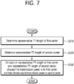
- FIG. 7 shows a transmission power allocation method of a terminal according to an embodiment of the present disclosure.
- the terminal may be configured for a first carrier and a second carrier for V2X signal transmission.
- the terminal determines the representative TTI length of the first carrier (S210), and after determining the representative TTI length of the second carrier (S220), then on the basis of the representative TTI length of the first carrier and the representative TTI length of the second carrier, a first transmission power is allocated to the first carrier, and then a second transmission power may be allocated to the second carrier (S230).
- the representative TTI length of the first carrier may be shorter than the representative TTI length of the second carrier.
- the first transmission power may be greater value than the second transmission power.
- the representative TTI length of the first carrier may be determined as the maximum value or the minimum value among n and m.
- the first transmission power and the second transmission power may be allocated on the basis of the representative TTI length of the first carrier and the representative TTI length of the second carrier, priority per packet, or PPPP for each packet of signals transmitted in the first carrier and the second carrier, respectively and channel busy ratio (CBR).
- CBR channel busy ratio
- the PSSCH may be transmitted at a constant transmit power. This has been described with reference to FIG. 6 .
- the PSCCH and the PSSCH may be frequency division multiplexed (FDM).
- the transmit power of the PSSCH transmitted in the n symbols and the transmit power of the PSSCH transmitted in the m-n symbols may be different from each other.
- information indicating a difference or ratio between the transmission power of the PSSCH transmitted in the n symbols and the transmission power of the PSSCH transmitted in the m-n symbols on the PSCCH may be provided. This may be referred to FIG. 9 and the description below.
- FIG. 8 shows an example of applying the method of FIG. 7 .
- the PSCCH is transmitted in a slot (0.5 ms) unit. That is, the PSCCH is transmitted on the basis of the S-TTI.
- the PSSCH is transmitted in units of subframes.
- the value of the representative TTI is determined in the first carrier, and may be determined as 0.5ms or 1ms. For example, assume that the value of the representative TTI is determined to be 0.5ms in the first carrier.
- both PSCCH/PSSCH are transmitted in subframe units.
- the value of the representative TTI in the second carrier may be determined to be 1ms.
- the terminal may allocate a first transmission power to the first carrier and allocate a second transmission power to the second carrier, on the basis of the representative TTI length of the first carrier and the representative TTI length of the second carrier. For example, when transmission power is allocated to a relatively short TTI based transmission at high priority, the first transmission power may be allocated to the first carrier first, and then the second transmission power may be allocated to the second carrier. On the contrary, when the transmission power is allocated to the relatively long TTI based transmission with high priority, the second transmission power may be allocated to the second carrier first, and then the first transmission power may be allocated to the first carrier.
- a priority of allocating transmission powers in multiple carriers is determined on the basis of a representative TTI length, but it is not limited. That is, the priority for allocating the transmission power in multiple carriers may be determined in consideration of the representative TTI length of the carrier, the ProSe priority per packet (PPPP) of the message transmitted on the carrier, and the CBR.
- the PPPP may be called PPP as a priority per packet.
- the UE may transmit the PSCCH/PSSCH by the method of FIG. 6 described above.
- Open loop power control parameters (and/or maximum transmit power) for each S-TTI length may be configured (/signaled) independent of the existing 1 ms based legacy transmission (LEGACY TX).
- a parameter of a physical layer/CR_LIMIT value or the like associated with the CBR/PPPP for each S-TTI length may be independently configured (/signaled).
- a minimum guaranteed power value may be configured (/signaled) for each S-TTI length.
- V2X transmission resource reservation is made first in terms of power allocation, on a specific carrier #A
- V2X transmission resource reservation should be additionally performed on another carrier #B
- FIG. 9 shows another example of allocating transmission power to the PSCCH and the PSSCH.
- transmission power between symbols during PSSCH transmission may vary.
- the transmission power between the PSSCH region #A and the PSSCH region #B may be different.
- the following method may be considered for quadrature amplitude modulation (QAM) demodulation.
- QAM quadrature amplitude modulation
- the base station or the network may inform "transmission power difference (/ratio)" information between the PSSCH region #A and the PSSCH region #B through the PSCCH and/or a pool configuration signal.
- the transmission power difference (/ratio) information may be useful especially when there is no demodulation reference signal (DM-RS) symbol transmission in one of the PSSCH regions #A/B.
- DM-RS demodulation reference signal
- the transmission power difference (/ratio) information may be about the DM-RS symbol in the region #A and data symbol in the region #B.
- the network may signal the "maximum allowable transmit power difference (/ratio) between PSSCH region #A and PSSCH region #B" for a specific pool, thereby limiting the impact on sensing performance and the like.
- the network may fix the PSCCH length transmitted on a specific pool through predefined signaling, and/or allow a plurality of PSCCH lengths (transmissions), and allow the UE to blind decode (BLIND DECODING).
- the network may assign (or adjust) the number of PSCCH (/PSSCH) blind decoding of a UE to be performed on multiple pools related to multiple carriers in a carrier (/pool)-specific manner through predefined signaling.
- the present disclosure has been described a proposal method on the basis of the 3GPP LTE system for convenience of description, the scope of the system to which the proposed method is applied can be extended to other systems in addition to the 3GPP LTE system.
- the proposed schemes of the present disclosure can be extended and applied for D2D communication.
- the D2D communication means that the terminal communicates directly with another terminal using a wireless channel.
- the terminal means a terminal of a user, but network equipment such as a base station may also be regarded as a kind of terminal when transmitting/receiving a signal according to a communication method between the terminals.
- the proposed schemes of the present disclosure may be limitedly applied only to mode 3 V2X operation (and/or mode 4 V2X operation).
- the proposed schemes of the present disclosure may be limitedly applied only to (specific) V2X channel (/signal) transmissions that are pre-configured (/signaled), e.g., PSSCH (and/or (associated) PSCCH and/or PSBCH).
- the proposed schemes of the present disclosure may be limitedly applied only to when the PSSCH and the (associated) PSCCH are transmitted adjacent to (and/or non-adjacent) in the frequency domain (and/ or when pre-configured (/signaled) MCS (and/or coding rate and/or resource block) (value (/range)) based transmission is performed).
- the proposed schemes of the present disclosure may be limitedly applied only to between mode # 3 (and/or mode # 4) V2X carrier (and/or (mode # 4 (/3)) sidelink (/uplink) SPS (and/or sidelink (/uplink) dynamic scheduling) carrier).
- the proposed schemes of the present disclosure may be (limitedly) applied only to when synchronization signal (transmission (and/or reception)) resource location and/or the number of the resource (and/or V2X resource pool related subframe location and/ or the number of subframes (and/or the sub-channel size and/or the number of sub-channels) is the same (and/or (partially) different).
- FIG. 10 is a block diagram illustrating an apparatus in which an embodiment of the present disclosure is implemented.
- the apparatus 1000 includes a processor 1100, a memory 1200, and a transceiver 1300.
- the processor 1100 implements the proposed functions, processes, and/or methods.
- the apparatus 1000 may be a terminal or a base station.
- the transceiver 1300 is connected to the processor 1100 to transmit and receive a radio signal.
- the memory 1200 may store information necessary for the operation of the processor 1100 and may also store a transmission/reception signal.
- FIG. 11 shows an example of configuring the processor 1100.
- the processor 1100 may include a representative TTI determination module 1101 for determining a representative TTI for each carrier and a power allocation module 1102 for determining transmission power allocated for each carrier.
- the processor may include Application-Specific Integrated Circuits (ASICs), other chipsets, logic circuits, and/or data processors.
- the memory may include Read-Only Memory (ROM), Random Access Memory (RAM), flash memory, memory cards, storage media and/or other storage devices.
- the RF unit may include a baseband circuit for processing a radio signal.
- the above-described scheme may be implemented using a module (process or function) which performs the above function.
- the module may be stored in the memory and executed by the processor.
- the memory may be disposed to the processor internally or externally and connected to the processor using a variety of well-known means.
Description
- The present disclosure relates to wireless communication and, more particularly, to a power allocation method of a terminal having multiple carriers configured and the terminal using the same.
- Recently, interest in D2D (Device-to-Device) technology for direct communication between devices is being increased. In particular, D2D is drawing attention as a communication technology for a public safety network. Public safety networks have higher service requirements (reliability and security) than commercial communication networks, and also require direct signal transmission, or D2D operation, between devices, even when it is not covered by the coverage of cellular communications or it is not available for the cellular communications.
- D2D operation may have various advantages in that it transmits and receives signals between adjacent devices. For example, the D2D user equipment has a high data rate and low latency and can perform data communication. In addition, the D2D operation may distribute traffic congested at the base station, and may also serve to extend the coverage of the base station when the D2D terminal serves as a relay.
- Meanwhile, in LTE-A (long term evolution-advanced), an interface used for D2D operation, that is, an interface between a terminal and a terminal is called a sidelink, and the sidelink may also be used in communications between terminals installed in vehicles, or communications, i.e., vehicle-to-everything (V2X) between the terminal installed in vehicles and another terminal.
- In the existing V2X communication, it is assumed that mainly one carrier is used, but in the future wireless communication system, it is possible to support the use of multiple carriers for V2X communication.
- Meanwhile, the sidelink communication may transmit control signals, data, and the like while maintaining a transmission time interval (TTI) in an existing system, or may transmit control signals, data, and the like, using a shorter TTI than the existing system. Or, for example, one of the control signals and data may be transmitted using an existing TTI and the other thereof may be transmitted using the short TTI. Or, control signals may be transmitted using one TTI among various TTIs shorter than the existing TTI, and data may be transmitted using any other TTI among them. In relation to V2X communication, the various signal transmission schemes may be independently configured for each carrier.
- This operation is a new operation that has not existed previously, and thus, it may be an issue on in which scheme of allocating transmission power for each carrier.
-
U.S. patent application publication No. 2016/255594 A1 discusses power control and power headroom for component carrier. The 3GPP Draft No. R1-166806, entitled "Aggregation of NR carriers," discusses aspects related to Carrier Aggregation operation among NR carriers. - The present disclosure has been made in an effort to provide a power allocation method of a terminal having multiple carriers configured and a terminal using the method.
- In one aspect, provided is a method for allocating a first transmission power and a second transmission power as set forth in the appended claims.
- In another aspect, provided is a terminal as set forth in the appended claims.
- According to the present disclosure, a representative TTI for each carrier is determined, and transmission power for each carrier is allocated on the basis of the representative TTI value of each carrier. Since the transmission power for each carrier is determined in consideration of the TTI for each carrier, reliability of signal transmission can be improved. For example, when higher transmission power is allocated to a carrier using a short TTI, transmission reliability of a signal transmitted on the carrier can be increased. In addition, though various TTIs are used for any carrier, transmission power is allocated on the basis of a representative TTI, thereby reducing complexity.
-
-
FIG. 1 illustrates a wireless communication system. -
FIG. 2 is a block diagram showing the structure of a radio protocol on the user plane. -
FIG. 3 is a block diagram showing the structure of a radio protocol on the control plane. -
FIG. 4 illustrates scenarios for V2X communication. -
FIG. 5 shows an example of transmission of a PSCCH and a PSSCH. -
FIG. 6 shows a transmission power determination method according to an embodiment of the present disclosure. -
FIG. 7 shows a transmission power allocation method of a terminal according to an embodiment of the present disclosure. -
FIG. 8 shows an example of applying the method ofFIG. 7 . -
FIG. 9 shows another example of allocating transmission power to the PSCCH and the PSSCH. -
FIG. 10 is a block diagram illustrating an apparatus in which an embodiment of the present disclosure is implemented. -
FIG. 11 shows an example of configuring theprocessor 1100. -
FIG. 1 shows a wireless communication system. - The wireless communication system may also be referred to as an evolved-UMTS terrestrial radio access network (E-UTRAN) or a long term evolution (LTE)/LTE-A system.
- The E-UTRAN includes at least one base station (BS) 20 which provides a control plane and a user plane to a user equipment (UE) 10. The UE 10 may be fixed or mobile, and may be referred to as another terminology, such as a mobile station (MS), a user terminal (UT), a subscriber station (SS), a mobile terminal (MT), a wireless device, etc. The
BS 20 is generally a fixed station that communicates with the UE 10 and may be referred to as another terminology, such as an evolved node-B (eNB), a base transceiver system (BTS), an access point, etc. - The
BSs 20 are interconnected by means of an X2 interface. TheBSs 20 are also connected by means of an S1 interface to an evolved packet core (EPC) 30, more specifically, to a mobility management entity (MME) through S1-MME and to a serving gateway (S-GW) through S1-U. - The
EPC 30 includes an MME, an S-GW, and a packet data network-gateway (P-GW). The MME has access information of the UE or capability information of the UE, and such information is generally used for mobility management of the UE. The S-GW is a gateway having an E-UTRAN as an end point. The P-GW is a gateway having a PDN as an end point. - Layers of a radio interface protocol between the UE and the network can be classified into a first layer (L1), a second layer (L2), and a third layer (L3) based on the lower three layers of the open system interconnection (OSI) model that is well-known in the communication system. Among them, a physical (PHY) layer belonging to the first layer provides an information transfer service by using a physical channel, and a radio resource control (RRC) layer belonging to the third layer serves to control a radio resource between the UE and the network. For this, the RRC layer exchanges an RRC message between the UE and the BS.
- The wireless communication system may be a time division duplex (TDD) system, a frequency division duplex (FDD) system, or a system in which TDD and FDD are used together.
-
FIG. 2 is a diagram showing a wireless protocol architecture for a user plane.FIG. 3 is a diagram showing a wireless protocol architecture for a control plane. The user plane is a protocol stack for user data transmission. The control plane is a protocol stack for control signal transmission. - Referring to
FIGs. 2 and3 , a PHY layer provides an upper layer with an information transfer service through a physical channel. The PHY layer is connected to a medium access control (MAC) layer which is an upper layer of the PHY layer through a transport channel. Data is transferred between the MAC layer and the PHY layer through the transport channel. The transport channel is classified according to how and with what characteristics data is transferred through a radio interface. - Data is moved between different PHY layers, that is, the PHY layers of a transmitter and a receiver, through a physical channel. The physical channel may be modulated according to an Orthogonal Frequency Division Multiplexing (OFDM) scheme, and use the time and frequency as radio resources.
- The functions of the MAC layer include mapping between a logical channel and a transport channel and multiplexing and demultiplexing to a transport block that is provided through a physical channel on the transport channel of a MAC Service Data Unit (SDU) that belongs to a logical channel. The MAC layer provides service to a Radio Link Control (RLC) layer through the logical channel.
- The functions of the RLC layer include the concatenation, segmentation, and reassembly of an RLC SDU. In order to guarantee various types of Quality of Service (QoS) required by a Radio Bearer (RB), the RLC layer provides three types of operation mode: Transparent Mode (TM), Unacknowledged Mode (UM), and Acknowledged Mode (AM). AM RLC provides error correction through an Automatic Repeat Request (ARQ).
- The RRC layer is defined only on the control plane. The RRC layer is related to the configuration, reconfiguration, and release of radio bearers, and is responsible for control of logical channels, transport channels, and PHY channels. An RB means a logical route that is provided by the first layer (PHY layer) and the second layers (MAC layer, the RLC layer, and the PDCP layer) in order to transfer data between UE and a network.
- The function of a Packet Data Convergence Protocol (PDCP) layer on the user plane includes the transfer of user data and header compression and ciphering. The function of the PDCP layer on the user plane further includes the transfer and encryption/integrity protection of control plane data.
- What an RB is configured means a process of defining the characteristics of a wireless protocol layer and channels in order to provide specific service and configuring each detailed parameter and operating method. An RB can be divided into two types of a Signaling RB (SRB) and a Data RB (DRB). The SRB is used as a passage through which an RRC message is transmitted on the control plane, and the DRB is used as a passage through which user data is transmitted on the user plane.
- If RRC connection is established between the RRC layer of UE and the RRC layer of an E-UTRAN, the UE is in the RRC connected state. If not, the UE is in the RRC idle state.
- A downlink transport channel through which data is transmitted from a network to UE includes a broadcast channel (BCH) through which system information is transmitted and a downlink shared channel (SCH) through which user traffic or control messages are transmitted. Traffic or a control message for downlink multicast or broadcast service may be transmitted through the downlink SCH, or may be transmitted through an additional downlink multicast channel (MCH). Meanwhile, an uplink transport channel through which data is transmitted from UE to a network includes a random access channel (RACH) through which an initial control message is transmitted and an uplink shared channel (SCH) through which user traffic or control messages are transmitted.
- Logical channels that are placed over the transport channel and that are mapped to the transport channel include a broadcast control channel (BCCH), a paging control channel (PCCH), a common control channel (CCCH), a multicast control channel (MCCH), and a multicast traffic channel (MTCH).
- The physical channel includes several OFDM symbols in the time domain and several subcarriers in the frequency domain. One subframe includes a plurality of OFDM symbols in the time domain. An RB is a resources allocation unit, and includes a plurality of OFDM symbols and a plurality of subcarriers. Furthermore, each subframe may use specific subcarriers of specific OFDM symbols (e.g., the first OFDM symbol) of the corresponding subframe for a physical downlink control channel (PDCCH), that is, an L1/L2 control channel. A Transmission Time Interval (TTI) is a unit time for subframe transmission.
- The RRC state refers to whether or not the RRC layer of the UE is in a logical connection with the RRC layer of the E-UTRAN, and when it is connected, it is called an RRC connected state (RRC_CONNECTED) and when it is not connected, it is called an RRC idle state (RRC_IDLE). Since the UE in the RRC connected state has an RRC connection, the E-UTRAN can identify the existence of the corresponding UE in a cell unit, and thus can effectively control the UE. On the other hand, the UE of the RRC idle state cannot be identified by the E-UTRAN, and is managed by the CN (core network) in units of a tracking area, which is a larger area than a cell. That is, whether or not the UE is in the RRC idle state is identified only in a large area unit, and should move to to the RRC connected state in order to receive a normal mobile communication service such as voice or data.
- When a user initially powers on the UE, the UE first searches for an appropriate cell and then stays in an RRC idle state in the cell. When the UE in the RRC idle state needs to establish an RRC connection, it establishes an RRC connection with the E-UTRAN through an RRC connection procedure and transitions to the RRC connected state. There are several cases in which the UE in RRC idle state needs to establish an RRC connection. For example, the cases may be that an uplink data transmission is necessary due to a user's call attempt or the like, or when a paging message from E-UTRAN is received, a response message or the like is transmitted in response to the paging message.
- The non-access stratum (NAS) layer located in the upper layer of the RRC layer performs functions such as session management, mobility management and the like.
- In order to manage mobility of the UE in the NAS layer, two states of EMM-REGISTERED (EPS Mobility Management-REGISTERED) and EMM-DEREGISTERED are defined, and these two states are applied to the UE and the MME. The initial UE is in the EMM-DEREGISTERED state, and the UE performs a process of registering with the corresponding network through an initial attach procedure to access the network. When the attach procedure is successfully performed, the UE and the MME are in the EMM-REGISTERED state.
- In order to manage a signaling connection between the UE and the EPC, two states are defined, an EPS Connection Management (ECM)-IDLE state and an ECM-CONNECTED state, and these two states are applied to the UE and the MME. When the UE in the ECM-IDLE state establishes an RRC connection with the E-UTRAN, the UE is in the ECM-CONNECTED state. The MME in the ECM-IDLE state becomes the ECM-CONNECTED state when it establishes an S1 connection with the E-UTRAN. When the UE is in the ECM-IDLE state, the E-UTRAN does not have context information of the UE. Accordingly, the UE in the ECM-IDLE state performs a UE-based mobility related procedure such as cell selection or cell reselection without receiving a command from the network. On the other hand, when the UE is in the ECM-CONNECTED state, the mobility of the UE is managed by the command of the network. In the ECM-IDLE state, when the position of the terminal is different from the position known by the network, the UE informs the network of the corresponding position of the UE through a tracking area update procedure.
- The D2D operation will be now described. In 3GPP LTE-A, a service related to D2D operation is called proximity based services (ProSe). Hereinafter, ProSe is an equivalent concept to D2D operation, and ProSe may be used by being mixed with D2D operation. Now, the ProSe will be now described.
- The ProSe has ProSe communication and ProSe direct discovery. The ProSe direct communication refers to communication performed between two or more neighboring UEs. The UEs may perform communication using a user plane protocol. The ProSe-enabled UE refers to the UE that supports a procedure related to the requirements of ProSe. Unless otherwise stated, the ProSe-enabled UE include both a public safety UE and a non-public safety UE. The public safety UE is a terminal that supports both a public safety-specific function and a ProSe process. The non-public safety UE is the UE that supports a ProSe process but does not support the public safety-specific function.
- The ProSe direct discovery is a process for the ProSe-enabled UE to discover other ProSe-enabled UE that are adjacent to each other, using only the capabilities of the two ProSe-enabled UEs. EPC-level ProSe discovery refers to a process in which an EPC determines whether two ProSe-enabled UEs are in proximity and informs the two ProSe-enabled UEs of their proximity.
- Hereinafter, for convenience, the ProSe direct communication may be referred to as D2D communication and the ProSe direct discovery may be referred to as D2D discovery. The link used for D2D operation is called sidelink in LTE.
- The V2X (vehicle to everything) communication will be now described. The V2X means communication between a UE installed in a vehicle and another UE, and the other UE may be a pedestrian, a vehicle, or an infrastructure, and in this case, it may be referred to as a vehicle to pedestrian (V2P), a vehicle to vehicle (V2V), a vehicle to infrastructure (V2I) and the like.
- In the V2X communication, data/control information may be transmitted and received through a sidelink defined in a D2D operation other than an uplink/downlink link between a base station and a UE used in the existing LTE communication.
- The following physical channels may be defined in the sidelink.
- Physical Sidelink Broadcast Channel (PSBCH) is a physical sidelink broadcast channel. Physical Sidelink Control Channel (PSCCH) is a physical sidelink control channel. Physical Sidelink Discovery Channel (PSDS) is a physical sidelink discovery channel. Physical Sidelink Shared Channel (PSSCH) is a physical sidelink shared channel. Sidelink Synchronization Signal (SLSS) is a sidelink synchronization signal. The SLSS may include a Primary Sidelink Synchronization Signal (PSSS) and a Secondary Sidelink Synchronization Signal (SSSS). The SLSS and the PSBCH may be transmitted together.
- The sidelink may mean an interface between the terminal and the terminal, and the sidelink may correspond to the PC5 interface.
-
FIG. 4 illustrates scenarios for V2X communication. - Referring to
FIG. 4 (a) , V2X communication may support PC5-based information exchange operation (between UEs), which is an interface between the UEs, and it may also support Uu-based elaboration exchange operation (between UEs) corresponding to an interface between the base station (eNodeB) and the terminal (UE), as shown inFIG. 4 (b) . In addition, as shown inFIG. 4C , both PC5 and Uu may be used to support information exchange operations (between UEs). - Hereinafter, the present disclosure will be described on the basis of the 3GPP LTE/LTE-A system for convenience of description. However, the scope of the system to which the present disclosure is applied can be extended to other systems besides the 3GPP LTE/LTE-A system.
- The present disclosure will now be described.
- The proposed schemes below proposes methods for efficiently operating transmission power control when V2X communication on the basis of a relatively short transmission time interval (TRANSMISSION TIME INTERVAL) is performed compared to the existing interval (for example, "1ms (milliseconds)"). Hereinafter, for convenience, a transmission time interval shorter than the existing 1ms is called an S-TTI, and an existing transmission time interval of 1ms is called an L-TTI.
- In the future wireless communication systems, a variable TTI (channel/signal) may be introduced in consideration of traffic (or data) such as various transmission coverage/reliability/latency requirements. As an example, after a basic resource unit (BASIC RESOURCE UNIT) is defined (/configured), the TTI (for transmission of data related channel/signal of a specific requirement) may be defined as a singular or a combination of multiple basic resource units. For example, when an S-TTI is defined as a pre-configured (/signaled) base resource unit, the L-TTI may be interpreted in the form of is a combination of (a pre-configured (/signaled)) K S-TTIs. As another example, when the L-TTI is defined as a pre-configured (/signaled) base resource unit, the S-TTI may be interpreted as a form (e.g., a sort of MINI-BASIC RESOURCE UNIT) in which the L-TTI (Basic Resource Unit) is partitioned into (pre-configured (/signaled)) K units. As another example, the S-TTI may also have a form in which multiple (pre-configured (/signaled) basic resource units are combined.
- The V2X communication mode may be typically classified into a mode (A) (it is referred to as mode #3) in which a base station signals (/controls) scheduling information related to V2X message transmission (/reception) on a V2X resource pool pre-configured(/signaled) from a base station (/network) and a mode (B) (it is referred to as mode #4) in which a UE independently determines (/controls) V2X message transmission (/reception) related scheduling information on a V2X resource pool pre-configured(/signaled) from a base station (/network).
- The
mode # 3 may be, for example, subject to a UE located within the communication coverage by a base station, and/or a UE in an RRC_connected state. Themode # 4 may be, for example, subject to a UE located within/out of the communication coverage by a base station, and/or a UE in the RRC_connection/RRC_idle state. - Hereinafter, in the present disclosure, the "sensing operation" may be interpreted as a PSSCH-RSRP measurement operation on the basis of a PSSCH DM-RS sequence scheduled by a successfully decoded PSCCH and/or an S-RSSI measurement operation on the basis of a V2X resource pool related sub-channel, etc.
- In the present disclosure, "receiving" may be interpreted as being extended to at least one of (A) V2X channel (/signal) (e.g., PSCCH, PSSCH, PSBCH, PSSS/SSSS, etc.) decoding(/receiving) operation, WAN DL channel (/signal) (e.g., For example, PDCCH, PDSCH, PSS/SSS, etc.) decoding (/receiving) operation decoding, (B) sensing operation, and (C) CBR measurement operation.
- In the present disclosure, "transmitting" may be interpreted as being extended to at least one of a V2X channel (/signal) (e.g., PSCCH, PSSCH, PSBCH, PSSS/SSSS, etc.) transmission operation, WAN UL channel (/signal) (e.g., PUSCH, PUCCH, SRS, etc.) transmission operation.
- In the present disclosure, a "carrier" may be interpreted as being extended to at least one of (A) pre-configured (/signalled) carrier set (/group), (B) V2X resource pool.
- In the following description, it is assumed the situation that the PSCCH and the PSSCH associated therewith is transmitted in the form of "frequency division multiplexing" (FDM). However, this is not a limitation, and it is obvious that the present disclosure may be extended and applied even in a situation in which the PSCCH and the PSSCH associated therewith is transmitted in the form of "time division multiplexing" (TDM) or a combination of FDM and TDM.
- Sidelink Received Signal Strength Indicator (S-RSSI), Sidelink Reference Signal Received Power (S-RSRP), Channel busy ratio (CBR) and Channel occupancy ratio (CR) will be described.
- First, S-RSSI is a received signal strength indicator in the sidelink. The S-RSSI may be defined as a linear average of the total received power for each SC-FDMA symbol, measured by the UE in the configured sub-channel, in SC-
FDMA symbols # FDMA symbols # - The S-RSRP means the reference signal reception power in the sidelink. For example, the S-RSRP may include a PSSCH-RSRP obtained by calculating an RSRP from a PSSCH. The PSSCH-RSRP may be defined as a linear average of the power contributions of resource elements (REs) carrying a demodulation reference signal (DM-RS) associated with the PSSCH, within the physical resource blocks (PRBs) indicated by the associated PSCCH.
- The CBR indicates the busy ratio of the channel, and the CBR measured in subframe n may be defined as follows.
- In the case of the PSSCH, it is sensed in the subframe [n-100, n-1] and represents the ratio in the resource pool of the sub-channel having the S-RSSI measured as exceeding a predetermined or configured threshold.
- In case of PSCCH, it is sensed in subframe [n-100, n-1], and, in a pool configured to transmit PSCCH together with corresponding PSSCH in non-contiguous resource blocks, indicates the ratio of resources of the PSCCH pool with S-RSSI measured as being above a predetermined or configured threshold. Here, it is assumed that the PSCCH pool is composed of resources of two consecutive PRB pairs in the frequency domain.
- The CR means channel occupancy. The CR calculated in subframe n may be defined as a value of the total sum of the number of sub-channels used for its transmission in subframe [n-a, n-1] and the number of sub-channels allowed for its transmission in subframe [n, n+b] divided by total number of sub-channels configured in the transmission pool over subframes [n-a, n+b].
- Here, the 'a' is a positive integer and 'b' is 0 or a positive integer. The 'a, b' is determined by the UE, has a relationship of a+b+1=1000, 'a' is 500 or more, n+b should not exceed the most recent transmission opportunity of the grant for the current transmission. The CR may be evaluated for every (re-)transmission. The CR may be calculated for each priority level.
- Hereinafter, S-PSCCH_L means the number of symbols constituting the S-TTI-based PSCCH, S-PSSCH_L means the number of symbols constituting the S-TTI-based PSSCH.
- And, hereinafter, S-PSCCH means S-TTI based PSCCH, S-PSSCH means S-TTI based PSSCH.
- Hereinafter, it is assumed that the (S-)PSSCH associated with the (S-)PSCCH is transmitted in the form of "FDM".
-
FIG. 5 shows an example of transmission of a PSCCH and a PSSCH. - Referring to
FIG. 5 , the PSCCH and the PSSCH scheduled by the PSCCH, that is, the associated PSSCHs may be transmitted through different frequencies (FDM). - In
Fig. 5(a) , it is S-PSCCH_L = S-PSSCH_L. That is, in the time domain, the number of symbols constituting the S-TTI based PSCCH and the number of symbols constituting the S-TTI based PSSCH are the same. - In
Fig. 5(b) , it is S-PSCCH_L < S-PSSCH_L. That is, in the time domain, the number of symbols constituting the S-TTI based PSSCH is larger than the number of symbols constituting the S-TTI based PSCCH. - In
Fig. 5(c) , it is S S-PSCCH_L > S-PSSCH_L. That is, in the time domain, the number of symbols constituting the S-TTI based PSSCH is smaller than the number of symbols constituting the S-TTI based PSCCH. - As shown in
FIG. 5(a) , in the case of S-PSCCH_L = S-PSSCH_L, the transmission power may be determined in the same manner as the existing 1 ms TTI-based operation. - For example, the transmission power may be determined as follows for the S-PSSCH.
- In the sidelink transmission mode 3 (mode 3), PPSSCH for PSSCH transmission may be determined as the following equation.

- In
Equation 1, PCMAX is a configured maximum UE output power. MPSSCH is a band of PSSCH resource allocation expressed in number of resource blocks. PL means a path loss. PO_PSSCH,3, αPSSCH,3 is a value provided by an upper layer parameter associated with a corresponding PSSCH resource configuration. - In the case of sidelink transmission mode 4 (mode 4), PPSSCH for PSSCH transmission may be determined as follows.

- In the case of sidelink transmission mode 4 (mode 4), PPSSCH for PSSCH transmission may be determined as the following equation. The PPSSCH is two.
- The 'A' may be given by
Equation 

- When the upper layer parameter 'maxTxpower' is configured,
equation 3 may be used, otherwiseequation 4 may be used. PO_PSSCH,4, αPSSCH,4 is a value provided by upper layer parameters associated with the corresponding PSSCH resource configuration. PMAX_CBR may be configured to the upper layer parameter 'maxTxpower' value on the basis of the priority level of the PSCCH and the CBR range. -
FIG. 6 shows a transmission power determination method according to an embodiment of the present disclosure. - Referring to
FIG. 6 , when S-PSCCH_L < S-PSSCH_L (the situation inFIG. 5B ). That is, on the time axis, a partial overlap occurs in the time domain between S-PSCCH transmission and S-PSSCH transmission. In other words, some of the symbols used for S-PSSCH transmission overlap with the symbols used for S-PSCCH transmission in the time domain. In this case, it is not desirable to increase the transmit power in symbols of the S-PSSCH where no overlap occurs. In this case, an additional power transition period (POWER TRANSIENT PERIOD) occurs and the transmission power between symbols in a single S-TTI is changed and it may adversely affect the sensing performance. In other words, the transmission power in the symbol of the overlapped S-PSSCH may be maintained the same also in the symbols (regions) of the S-PSSCH in which the remaining overlap has not occurred. - Next, in the situation as shown in
FIG. 5(c) , that is, in the case of S-PSCCH_L> S-PSSCH_L, the transmission power of the S-PSCCH in the overlapping symbol may be maintained constantly even in the S-PSCCH in the non-overlapping symbol. - A transmission power determination method in transmitting signals on multiple carriers will be now described.
- The priority rule of power allocation (POWER ALLOCATION) may be defined as one or a combination of the following rules.
- The representative S-TTI length related to V2X transmission on a specific carrier may be assumed to be a maximum value (or minimum value) among S-PSCCH_L and S-PSSCH_L.
- (Rule #A) The transmit power with high priority may be allocated to relatively short (or long) length S-TTI based transmission. For example, using a small number of symbols and at the same time reducing transmission power can cause a lot of performance degradation, so that transmission power can be allocated at high priority to relatively short length S-TTI based transmissions.
- (Rule #B) The transmit power with high priority may be allocated to the ProSe priority per packet (PPPP) based V2X transmission (e.g., purposes for determining prioritization between V2X transmission(s)) higher (or lower) and/or (simultaneously) relatively higher (or lower) thresholds (e.g., purposes for determining prioritization between V2X/uplink transmission(s)). For example, by comparing the PPPP value (first PPPP value) of the V2X message to be transmitted on the first carrier with the PPPP value (second PPPP value) of the V2X message to be transmitted on the second carrier, when the first PPPP value is higher and the rest of the other conditions are the same, then it is to firstly allocate transmit power to the first carrier.
- (Rule #C) For a pre-configured (/signaled) specific signal/channel transmission (e.g., SLSS/PSBCH), transmit power may be allocated at an exceptionally high (or low) priority. For example, when the location of the SLSS/PSBCH resource is differently configured (/signaled) between the carriers, the transmission power is preferentially allocated at the corresponding time point of the carrier including the resource.
- (Rule #D) The transmit power may be allocated at a high priority to transmission on a carrier in which a relatively high (or low) CBR is measured, or on a carrier with less (or more) resources left than CR_LIMIT.
- (Example) Rule (B) is applied by default, but when the priority is the same between V2X transmission(s), and then the Rule (A) (and/or Rule (D) and/or Rule (C)) may be applied for TIE-BREAKER purposes.
-
FIG. 7 shows a transmission power allocation method of a terminal according to an embodiment of the present disclosure. - Referring to
FIG. 7 , the terminal may be configured for a first carrier and a second carrier for V2X signal transmission. - In this case, the terminal determines the representative TTI length of the first carrier (S210), and after determining the representative TTI length of the second carrier (S220), then on the basis of the representative TTI length of the first carrier and the representative TTI length of the second carrier, a first transmission power is allocated to the first carrier, and then a second transmission power may be allocated to the second carrier (S230).
- In this case, for example, the representative TTI length of the first carrier may be shorter than the representative TTI length of the second carrier. In this case, the first transmission power may be greater value than the second transmission power.
- When the number of symbols to which the PSCCH is transmitted on the first carrier is n (n is a natural number) and the number of symbols to which the PSSCH is transmitted is m (m is a natural number), the representative TTI length of the first carrier may be determined as the maximum value or the minimum value among n and m.
- The first transmission power and the second transmission power may be allocated on the basis of the representative TTI length of the first carrier and the representative TTI length of the second carrier, priority per packet, or PPPP for each packet of signals transmitted in the first carrier and the second carrier, respectively and channel busy ratio (CBR).
- When the number of symbols to which the PSCCH is transmitted in the first carrier is n (n is a natural number), the number of symbols to which the PSSCH is transmitted is m (m is a natural number), and m is greater than the number n, the PSSCH may be transmitted at a constant transmit power. This has been described with reference to
FIG. 6 . The PSCCH and the PSSCH may be frequency division multiplexed (FDM). - Alternatively, when the number of symbols on which the PSCCH is transmitted in the first carrier is n (n is a natural number), the number of symbols on which the PSSCH is transmitted is m (m is a natural number), and m is larger than n, the transmit power of the PSSCH transmitted in the n symbols and the transmit power of the PSSCH transmitted in the m-n symbols may be different from each other. In this case, information indicating a difference or ratio between the transmission power of the PSSCH transmitted in the n symbols and the transmission power of the PSSCH transmitted in the m-n symbols on the PSCCH may be provided. This may be referred to
FIG. 9 and the description below. -
FIG. 8 shows an example of applying the method ofFIG. 7 . - Referring to
FIG. 8 , in the first carrier, the PSCCH is transmitted in a slot (0.5 ms) unit. That is, the PSCCH is transmitted on the basis of the S-TTI. On the other hand, the PSSCH is transmitted in units of subframes. - In this case, the value of the representative TTI is determined in the first carrier, and may be determined as 0.5ms or 1ms. For example, assume that the value of the representative TTI is determined to be 0.5ms in the first carrier.
- In the second carrier, both PSCCH/PSSCH are transmitted in subframe units. In this case, the value of the representative TTI in the second carrier may be determined to be 1ms.
- The terminal may allocate a first transmission power to the first carrier and allocate a second transmission power to the second carrier, on the basis of the representative TTI length of the first carrier and the representative TTI length of the second carrier. For example, when transmission power is allocated to a relatively short TTI based transmission at high priority, the first transmission power may be allocated to the first carrier first, and then the second transmission power may be allocated to the second carrier. On the contrary, when the transmission power is allocated to the relatively long TTI based transmission with high priority, the second transmission power may be allocated to the second carrier first, and then the first transmission power may be allocated to the first carrier.
- In
FIGS. 7 and8 , an example in which a priority of allocating transmission powers in multiple carriers is determined on the basis of a representative TTI length, but it is not limited. That is, the priority for allocating the transmission power in multiple carriers may be determined in consideration of the representative TTI length of the carrier, the ProSe priority per packet (PPPP) of the message transmitted on the carrier, and the CBR. The PPPP may be called PPP as a priority per packet. - In the above-described manner, after the transmission power for each carrier is determined in multiple carriers, within the transmission power allocated for the corresponding carrier, the UE may transmit the PSCCH/PSSCH by the method of
FIG. 6 described above. - Open loop power control parameters (and/or maximum transmit power) for each S-TTI length (e.g. P_O, ALPHA, P_MAX, etc.) may be configured (/signaled) independent of the existing 1 ms based legacy transmission (LEGACY TX).
- In addition, a parameter of a physical layer/CR_LIMIT value or the like associated with the CBR/PPPP for each S-TTI length may be independently configured (/signaled).
- A minimum guaranteed power value may be configured (/signaled) for each S-TTI length.
- In a situation where a high priority, V2X transmission resource reservation is made first in terms of power allocation, on a specific carrier #A, when a low priority, V2X transmission resource reservation should be additionally performed on another carrier #B, it is possible to preferentially use the previously reserved resources on the carrier #A, the resources of carrier #B that do not overlap (all or in part) in the time domain.
-
FIG. 9 shows another example of allocating transmission power to the PSCCH and the PSSCH. - Referring to
FIG. 9 , transmission power between symbols during PSSCH transmission may vary. For example, the transmission power between the PSSCH region #A and the PSSCH region #B may be different. In this case, the following method may be considered for quadrature amplitude modulation (QAM) demodulation. - The base station or the network may inform "transmission power difference (/ratio)" information between the PSSCH region #A and the PSSCH region #B through the PSCCH and/or a pool configuration signal. The transmission power difference (/ratio) information may be useful especially when there is no demodulation reference signal (DM-RS) symbol transmission in one of the PSSCH regions #A/B. For example, when there is a DM-RS symbol transmission only on the region #A, the transmission power difference (/ratio) information may be about the DM-RS symbol in the region #A and data symbol in the region #B.
- Additionally, the network may signal the "maximum allowable transmit power difference (/ratio) between PSSCH region #A and PSSCH region #B" for a specific pool, thereby limiting the impact on sensing performance and the like.
- The network may fix the PSCCH length transmitted on a specific pool through predefined signaling, and/or allow a plurality of PSCCH lengths (transmissions), and allow the UE to blind decode (BLIND DECODING).
- The network may assign (or adjust) the number of PSCCH (/PSSCH) blind decoding of a UE to be performed on multiple pools related to multiple carriers in a carrier (/pool)-specific manner through predefined signaling.
- It is obvious that examples of the proposed scheme described above may also be regarded as a kind of proposed scheme, since they may be included as one of the implementation methods of the present disclosure. In addition, although the above-described proposal schemes may be independently implemented, some proposal schemes may be implemented in the form of combination (or merge).
- As an example, the present disclosure has been described a proposal method on the basis of the 3GPP LTE system for convenience of description, the scope of the system to which the proposed method is applied can be extended to other systems in addition to the 3GPP LTE system. As an example, the proposed schemes of the present disclosure can be extended and applied for D2D communication. Here, the D2D communication means that the terminal communicates directly with another terminal using a wireless channel. Here, for example, the terminal means a terminal of a user, but network equipment such as a base station may also be regarded as a kind of terminal when transmitting/receiving a signal according to a communication method between the terminals.
- In addition, as an example, the proposed schemes of the present disclosure may be limitedly applied only to
mode 3 V2X operation (and/ormode 4 V2X operation). - In addition, as an example, the proposed schemes of the present disclosure may be limitedly applied only to (specific) V2X channel (/signal) transmissions that are pre-configured (/signaled), e.g., PSSCH (and/or (associated) PSCCH and/or PSBCH).
- In addition, as an example, the proposed schemes of the present disclosure may be limitedly applied only to when the PSSCH and the (associated) PSCCH are transmitted adjacent to (and/or non-adjacent) in the frequency domain (and/ or when pre-configured (/signaled) MCS (and/or coding rate and/or resource block) (value (/range)) based transmission is performed).
- In addition, as an example, the proposed schemes of the present disclosure may be limitedly applied only to between mode # 3 (and/or mode # 4) V2X carrier (and/or (mode # 4 (/3)) sidelink (/uplink) SPS (and/or sidelink (/uplink) dynamic scheduling) carrier).
- In addition, as an example, the proposed schemes of the present disclosure may be (limitedly) applied only to when synchronization signal (transmission (and/or reception)) resource location and/or the number of the resource (and/or V2X resource pool related subframe location and/ or the number of subframes (and/or the sub-channel size and/or the number of sub-channels) is the same (and/or (partially) different).
-
FIG. 10 is a block diagram illustrating an apparatus in which an embodiment of the present disclosure is implemented. - Referring to
FIG. 10 , theapparatus 1000 includes aprocessor 1100, amemory 1200, and atransceiver 1300. Theprocessor 1100 implements the proposed functions, processes, and/or methods. Theapparatus 1000 may be a terminal or a base station. Thetransceiver 1300 is connected to theprocessor 1100 to transmit and receive a radio signal. Thememory 1200 may store information necessary for the operation of theprocessor 1100 and may also store a transmission/reception signal. -
FIG. 11 shows an example of configuring theprocessor 1100. - Referring to
FIG. 11 , theprocessor 1100 may include a representativeTTI determination module 1101 for determining a representative TTI for each carrier and apower allocation module 1102 for determining transmission power allocated for each carrier. - The processor may include Application-Specific Integrated Circuits (ASICs), other chipsets, logic circuits, and/or data processors. The memory may include Read-Only Memory (ROM), Random Access Memory (RAM), flash memory, memory cards, storage media and/or other storage devices. The RF unit may include a baseband circuit for processing a radio signal. When the above-described embodiment is implemented in software, the above-described scheme may be implemented using a module (process or function) which performs the above function. The module may be stored in the memory and executed by the processor. The memory may be disposed to the processor internally or externally and connected to the processor using a variety of well-known means.
Claims (8)
- A method for allocating a first transmission power and a second transmission power, the method performed by a user equipment (1000), UE, and comprising:allocating the first transmission power on a first carrier; andallocating the second transmission power on a second carrier, wherein, based on a length of a representative transmission time interval, TTI, of the first carrier and a length of a representative TTI of the second carrier, the UE allocates the second transmission power after allocating the first transmission power,wherein the length of the representative TTI of the first carrier is shorter than the representative TTI of the second carrier,wherein the first transmit power has a greater value than the second transmit power,characterized in that on the first carrier, the UE (1000) transmits a physical sidelink control channel, PSCCH, a first physical sidelink shared channel, PSSCH, and a second PSSCH,wherein the PSCCH and the first PSSCH are frequency division multiplexed and the PSCCH and the second PSSCH are frequency division multiplexed,wherein the region of the PSCCH overlaps with the region of the first PSSCH on a time domain, and the region of the PSCCH does not overlap with the region of the second PSSCH on the time domain,wherein a transmission power on the region of the first PSCCH is different from a transmission power on the region of the second PSCCH,wherein the UE (1000) receives, from a base station, a power difference information or power difference ratio information between the region of the first PSCCH and the region of the second PSCCH, andwherein a demodulation reference signal, DM-RS, symbol is only transmitted on the region of the first PSSCH and not transmitted on the region of the second PSSCH.
- The method of claim 1, wherein a number of symbols, on which the PSCCH is transmitted, is N,wherein a number of symbols on which the first PSSCH and the second PSSCH, are transmitted, is M on the first carrier,wherein the N is a natural number and the M is a natural number, andwherein the length of the representative TTI of the first carrier is determined based on a maximum value or minimum value among the N and the M.
- The method of claim 1, wherein the first transmission power and the second transmission power are allocated based on the length of the representative TTI of the first carrier, the length of the representative TTI of the second carrier, priority per packet and channel busy ratio, CBR, of signals transmitted on the first carrier and the second carrier, respectively.
- The method of claim 1, wherein the first carrier and the second carrier are 2. included in multiple carriers.
- A user equipment (1000), UE, comprising:a transceiver (1300) configured to transmit and receive radio signal; anda processor (1100) operably coupled to the transceiver (1300), wherein the processor (1100) is configured to:allocate a first transmission power on a first carrier; andallocate a second transmission power on a second carrier,wherein, based on a length of a representative transmission time interval, TTI, of the first carrier and a length of a representative TTI of the second carrier, the UE is configured to allocate the second transmission power after allocating the first transmission power,wherein the length of the representative TTI of the first carrier is shorter than the representative TTI of the second carrier,wherein the first transmit power has a greater value than the second transmit power,characterized in that the UE is further configured to transmit, on the first carrier, a physical sidelink control channel, PSCCH, a first physical sidelink shared channel, PSSCH, and a second PSSCH,wherein the PSCCH and the first PSSCH are frequency division multiplexed and the PSCCH and the second PSSCH are frequency division multiplexed,wherein the region of the PSCCH overlaps with the region of the first PSSCH on a time domain, and the region of the PSCCH does not overlap with the region of the second PSSCH on the time domain,wherein a transmission power on the region of the first PSCCH is different from a transmission power on the region of the second PSCCH,wherein the processor (1100) is further configured to receive, from a base station, a power difference information or power difference ratio information between the region of the first PSCCH and the region of the second PSCCH, andwherein a demodulation reference signal, DM-RS, symbol is only transmitted on the region of the first PSSCH and not transmitted on the region of the second PSSCH.
- The UE (1000) of claim 5, wherein a number of symbols, on which the PSCCH is transmitted, is N,wherein a number of symbols on which the first PSSCH and the second PSSCH, are transmitted, is M on the first carrier,wherein the N is a natural number and the M is a natural number, andwherein the length of the representative TTI of the first carrier is determined based on a maximum value or minimum value among the N and the M.
- The UE (1000) of claim 5, configured to allocate the first transmission power and the second transmission power based on the length of the representative TTI of the first carrier, the length of the representative TTI of the second carrier, the priority per packet and the channel busy ratio, CBR, of signals transmitted on the first carrier and the second carrier, respectively.
- The UE (1000) of claim 5, wherein the first carrier and the second carrier are included in multiple carriers.
Applications Claiming Priority (2)
| Application Number | Priority Date | Filing Date | Title |
|---|---|---|---|
| US201762476711P | 2017-03-24 | 2017-03-24 | |
| PCT/KR2018/003552 WO2018174688A1 (en) | 2017-03-24 | 2018-03-26 | Power allocation method of terminal having multiple carriers configured, and terminal using same |
Publications (3)
| Publication Number | Publication Date |
|---|---|
| EP3592070A1 EP3592070A1 (en) | 2020-01-08 |
| EP3592070A4 EP3592070A4 (en) | 2020-03-18 |
| EP3592070B1 true EP3592070B1 (en) | 2022-05-04 |
Family
ID=63584475
Family Applications (1)
| Application Number | Title | Priority Date | Filing Date |
|---|---|---|---|
| EP18771009.0A Active EP3592070B1 (en) | 2017-03-24 | 2018-03-26 | Power allocation method of terminal having multiple carriers configured, and terminal using same |
Country Status (6)
| Country | Link |
|---|---|
| US (1) | US11917555B2 (en) |
| EP (1) | EP3592070B1 (en) |
| JP (1) | JP6963026B2 (en) |
| KR (1) | KR102258653B1 (en) |
| CN (1) | CN110463315B (en) |
| WO (1) | WO2018174688A1 (en) |
Families Citing this family (10)
| Publication number | Priority date | Publication date | Assignee | Title |
|---|---|---|---|---|
| CN112352457A (en) * | 2018-08-07 | 2021-02-09 | 松下电器(美国)知识产权公司 | User equipment, base station and wireless communication method |
| CN110859005B (en) * | 2018-08-23 | 2023-04-21 | 华为技术有限公司 | Communication method and related equipment |
| EP3874778A4 (en) | 2018-11-01 | 2021-11-10 | Panasonic Intellectual Property Corporation of America | Transmitting apparatus, receiving apparatus and methods thereof |
| WO2020130757A1 (en) * | 2018-12-21 | 2020-06-25 | 엘지전자 주식회사 | Method and device for receiving signal by sidelink terminal in wireless communication system |
| CN113225796A (en) | 2018-12-24 | 2021-08-06 | 华为技术有限公司 | Power control method and device |
| US20220070680A1 (en) * | 2018-12-27 | 2022-03-03 | Sony Group Corporation | Communication control apparatus, communication apparatus, and proxy apparatus |
| CN111294940B (en) * | 2019-03-08 | 2023-04-21 | 展讯通信(上海)有限公司 | Transmission power distribution method and device, storage medium and terminal |
| US20220086767A1 (en) * | 2019-04-08 | 2022-03-17 | Apple Inc. | Nr v2x sidelink structures for pscch cover enhancement |
| KR102490599B1 (en) | 2019-04-28 | 2023-01-20 | 엘지전자 주식회사 | Method and apparatus for controlling sidelink transmission power in NR V2X |
| WO2021062613A1 (en) * | 2019-09-30 | 2021-04-08 | Oppo广东移动通信有限公司 | Data transmission method and device |
Family Cites Families (41)
| Publication number | Priority date | Publication date | Assignee | Title |
|---|---|---|---|---|
| AU2007200145A1 (en) * | 2006-01-18 | 2007-08-02 | Nec Australia Pty Ltd | Method of physical resource management in a wideband communication system |
| WO2007082754A1 (en) * | 2006-01-18 | 2007-07-26 | Telefonaktiebolaget L M Ericsson (Publ) | Localized and distributed transmission |
| EP2244515A1 (en) * | 2009-04-23 | 2010-10-27 | Panasonic Corporation | Logical channel prioritization procedure for generating multiple uplink transport blocks |
| US8817726B2 (en) * | 2009-07-26 | 2014-08-26 | Lg Electronics Inc. | Uplink transmission method and apparatus in wireless communication system |
| JP5542971B2 (en) * | 2010-02-25 | 2014-07-09 | エルジー エレクトロニクス インコーポレイティド | Apparatus and method for transmitting power headroom information in a multi-carrier system |
| BR112012025850B1 (en) * | 2010-04-09 | 2021-05-04 | Nokia Solutions And Networks Oy | signaling report transmission in a carrier aggregation |
| EP3086608B1 (en) * | 2010-08-17 | 2018-10-03 | Google Technology Holdings LLC | Method and apparatus for power headroom reporting during multi-carrier operation |
| US9432131B2 (en) * | 2014-11-28 | 2016-08-30 | Telefonaktiebolaget Lm Ericsson (Publ) | Method and apparatus for handling inter-modulation interference in a network node capable of FDD communications |
| US9900843B2 (en) * | 2015-01-12 | 2018-02-20 | Qualcomm Incorporated | Uplink power control techniques for ultra low latency in LTE devices |
| US9749970B2 (en) | 2015-02-27 | 2017-08-29 | Qualcomm Incorporated | Power control and power headroom for component carrier |
| WO2016143968A1 (en) | 2015-03-12 | 2016-09-15 | 엘지전자 주식회사 | Method for reducing transmission resource of control channel in short tti, and device using same |
| US10149255B2 (en) * | 2015-05-01 | 2018-12-04 | Qualcomm Incorporated | Low latency uplink power control |
| JPWO2017033490A1 (en) | 2015-08-21 | 2018-06-07 | 株式会社Nttドコモ | User apparatus, base station, communication method and instruction method |
| US10764866B2 (en) * | 2015-11-06 | 2020-09-01 | Sun Patent Trust | Multiple sidelink control transmissions during a sidelink control period |
| EP3361776A4 (en) * | 2015-11-09 | 2018-10-03 | Huawei Technologies Co., Ltd. | Transmission time interval switching method, communication system, user equipment and evolved node b |
| JP6805541B2 (en) * | 2016-05-11 | 2020-12-23 | ソニー株式会社 | Terminal equipment, communication method |
| US11153880B2 (en) * | 2016-08-09 | 2021-10-19 | Qualcomm Incorporated | Power allocation across multiple carriers using shared and dedicated radio frequency spectrum |
| US11115958B2 (en) * | 2016-08-09 | 2021-09-07 | Lg Electronics Inc. | Method whereby terminal transmits and receives sidelink signals in wireless communication system |
| EP3520532A1 (en) * | 2016-09-29 | 2019-08-07 | Telefonaktiebolaget LM Ericsson (PUBL) | Methods of selectively decoding scheduling assignments and/or sidelink data transmissions and related wireless communication devices |
| WO2018085118A1 (en) * | 2016-11-01 | 2018-05-11 | Intel IP Corporation | Downlink control information design with shorter tti |
| WO2018085045A1 (en) * | 2016-11-04 | 2018-05-11 | Intel IP Corporation | Wideband carrier configuration |
| EP3603293B1 (en) * | 2017-03-23 | 2023-03-15 | Apple Inc. | Prioritized messaging and resource selection in vehicle-to-vehicle (v2v) sidelink communication |
| CN110431893B (en) * | 2017-03-23 | 2023-08-29 | 苹果公司 | User equipment (UE) and method for vehicle-to-vehicle (V2V) side link communication according to short transmission time interval (TTI) |
| CN115460705A (en) * | 2017-03-23 | 2022-12-09 | 苹果公司 | Base band processor and method for base station and user equipment |
| WO2018174691A1 (en) * | 2017-03-24 | 2018-09-27 | 엘지전자 주식회사 | Method for transmitting sidelink synchronization signal in wireless communication system and terminal using same method |
| CN110612753B (en) * | 2017-05-05 | 2022-07-01 | Lg电子株式会社 | Power headroom reporting method in wireless communication system and apparatus thereof |
| US10750509B2 (en) * | 2017-08-10 | 2020-08-18 | Qualcomm Incorporated | Power reservation and dropping rules for transmission time intervals |
| US10904913B2 (en) * | 2017-08-14 | 2021-01-26 | Qualcomm Incorporated | Methods and apparatus for control channel scheduling in wireless communications |
| US10939321B2 (en) * | 2017-09-11 | 2021-03-02 | Apple Inc. | Power boosting and transport block size (TBS) design in a new radio (NR) system |
| US10554470B2 (en) * | 2017-12-21 | 2020-02-04 | Qualcomm Incorporated | Control monitoring and power control for multi-link deployments |
| US11277883B2 (en) * | 2018-05-11 | 2022-03-15 | Intel Corporation | Scheduling enhancements and hybrid automatic repeat request (HARQ) timing procedure for new radio (NR) unlicensed |
| US11678154B2 (en) * | 2018-07-30 | 2023-06-13 | Lg Electronics Inc. | V2X operating method based on TTI bundling in wireless communication system and terminal using same |
| WO2020168123A1 (en) * | 2019-02-13 | 2020-08-20 | Apple Inc. | System information design for new radio (nr) vehicle-to-everything (v2x) sidelink operation |
| WO2020168304A1 (en) * | 2019-02-14 | 2020-08-20 | Apple Inc. | Methods for simultaneous support of and switching between scheduled and ue autonomous resource selection modes for nr v2x sidelink |
| US20220132524A1 (en) * | 2019-03-18 | 2022-04-28 | Apple Inc. | Systems and methods for balancing time resource allocation to cellular vehicle-to-everything (c-v2x) and intelligent transport systems (its-g5) or dedicated short range communication (dsrc) depending on user configurations |
| US20220191733A1 (en) * | 2019-03-27 | 2022-06-16 | Apple Inc. | Assistance information indication for rat and interface selection for new radio vehicle-to-everything (v2x) |
| CN114270918B (en) * | 2019-08-21 | 2023-08-22 | 联想(新加坡)私人有限公司 | Method and apparatus for radio link failure recovery |
| WO2021062613A1 (en) * | 2019-09-30 | 2021-04-08 | Oppo广东移动通信有限公司 | Data transmission method and device |
| WO2021064015A1 (en) * | 2019-10-02 | 2021-04-08 | Fraunhofer-Gesellschaft zur Förderung der angewandten Forschung e.V. | Nr v2x retransmission procedures |
| US20220248430A1 (en) * | 2021-01-29 | 2022-08-04 | Qualcomm Incorporated | Demodulation reference signal bundling and frequency hopping |
| US20230224880A1 (en) * | 2022-03-17 | 2023-07-13 | Intel Corporation | Techniques for downlink and uplink resource mapping for full duplex and non-cell defining synchronization signal block |
-
2018
- 2018-03-26 JP JP2019552626A patent/JP6963026B2/en active Active
- 2018-03-26 WO PCT/KR2018/003552 patent/WO2018174688A1/en unknown
- 2018-03-26 CN CN201880020818.6A patent/CN110463315B/en active Active
- 2018-03-26 KR KR1020197026851A patent/KR102258653B1/en active IP Right Grant
- 2018-03-26 US US16/497,426 patent/US11917555B2/en active Active
- 2018-03-26 EP EP18771009.0A patent/EP3592070B1/en active Active
Also Published As
| Publication number | Publication date |
|---|---|
| EP3592070A1 (en) | 2020-01-08 |
| KR102258653B1 (en) | 2021-06-01 |
| EP3592070A4 (en) | 2020-03-18 |
| JP6963026B2 (en) | 2021-11-05 |
| US11917555B2 (en) | 2024-02-27 |
| US20230076122A1 (en) | 2023-03-09 |
| JP2020511907A (en) | 2020-04-16 |
| CN110463315A (en) | 2019-11-15 |
| KR20190110143A (en) | 2019-09-27 |
| WO2018174688A1 (en) | 2018-09-27 |
| CN110463315B (en) | 2023-12-01 |
Similar Documents
| Publication | Publication Date | Title |
|---|---|---|
| EP3592070B1 (en) | Power allocation method of terminal having multiple carriers configured, and terminal using same | |
| US20230156441A1 (en) | Method for selecting, in selection period, subframe excluding subframe relating to subframe in which transmission has been performed during sensing period in wireless communication system, and terminal using same | |
| US10536826B2 (en) | Method for selecting resource to be used for performing V2X communication within range satisfying latency requirement in wireless communication system, and terminal using same | |
| CN110100496B (en) | Method for transmitting signal by terminal for V2X communication in wireless communication system and apparatus using the same | |
| US11219035B2 (en) | Method and apparatus for deprioritizing duplicated packet transmission in wireless communication system | |
| KR102041943B1 (en) | A method for transmitting a v2x signal of a terminal having a limited transmission capability in a multi-carrier system and a terminal using the same | |
| US11516633B2 (en) | V2X communication method of terminal in wireless communication system and apparatus using same method | |
| US11051304B2 (en) | Method and apparatus for selecting carrier for sidelink transmission in wireless communication system | |
| KR102303212B1 (en) | Signal transmission method of a terminal for V2X communication in a wireless communication system and a terminal using the method | |
| US11350309B2 (en) | Method and apparatus for deprioritizing packet transmission based on reliability level or congestion level in wireless communication system | |
| US11095394B2 (en) | Method by which terminal blind-decodes physical sidelink control channel (PSCCH) in wireless communication system, and terminal using same | |
| US11115981B2 (en) | Method and apparatus for allocating resource based on anchor carrier in wireless communication system | |
| EP3592095B1 (en) | Transmission carrier selection for v2x serivces |
Legal Events
| Date | Code | Title | Description |
|---|---|---|---|
| STAA | Information on the status of an ep patent application or granted ep patent |
Free format text: STATUS: THE INTERNATIONAL PUBLICATION HAS BEEN MADE |
|
| PUAI | Public reference made under article 153(3) epc to a published international application that has entered the european phase |
Free format text: ORIGINAL CODE: 0009012 |
|
| STAA | Information on the status of an ep patent application or granted ep patent |
Free format text: STATUS: REQUEST FOR EXAMINATION WAS MADE |
|
| 17P | Request for examination filed |
Effective date: 20191002 |
|
| AK | Designated contracting states |
Kind code of ref document: A1 Designated state(s): AL AT BE BG CH CY CZ DE DK EE ES FI FR GB GR HR HU IE IS IT LI LT LU LV MC MK MT NL NO PL PT RO RS SE SI SK SM TR |
|
| AX | Request for extension of the european patent |
Extension state: BA ME |
|
| A4 | Supplementary search report drawn up and despatched |
Effective date: 20200213 |
|
| RIC1 | Information provided on ipc code assigned before grant |
Ipc: H04W 72/04 20090101AFI20200207BHEP |
|
| DAV | Request for validation of the european patent (deleted) | ||
| DAX | Request for extension of the european patent (deleted) | ||
| GRAP | Despatch of communication of intention to grant a patent |
Free format text: ORIGINAL CODE: EPIDOSNIGR1 |
|
| STAA | Information on the status of an ep patent application or granted ep patent |
Free format text: STATUS: GRANT OF PATENT IS INTENDED |
|
| GRAJ | Information related to disapproval of communication of intention to grant by the applicant or resumption of examination proceedings by the epo deleted |
Free format text: ORIGINAL CODE: EPIDOSDIGR1 |
|
| GRAP | Despatch of communication of intention to grant a patent |
Free format text: ORIGINAL CODE: EPIDOSNIGR1 |
|
| INTG | Intention to grant announced |
Effective date: 20211011 |
|
| INTG | Intention to grant announced |
Effective date: 20211103 |
|
| GRAS | Grant fee paid |
Free format text: ORIGINAL CODE: EPIDOSNIGR3 |
|
| GRAA | (expected) grant |
Free format text: ORIGINAL CODE: 0009210 |
|
| STAA | Information on the status of an ep patent application or granted ep patent |
Free format text: STATUS: THE PATENT HAS BEEN GRANTED |
|
| AK | Designated contracting states |
Kind code of ref document: B1 Designated state(s): AL AT BE BG CH CY CZ DE DK EE ES FI FR GB GR HR HU IE IS IT LI LT LU LV MC MK MT NL NO PL PT RO RS SE SI SK SM TR |
|
| REG | Reference to a national code |
Ref country code: GB Ref legal event code: FG4D |
|
| REG | Reference to a national code |
Ref country code: CH Ref legal event code: EP |
|
| REG | Reference to a national code |
Ref country code: AT Ref legal event code: REF Ref document number: 1490509 Country of ref document: AT Kind code of ref document: T Effective date: 20220515 |
|
| REG | Reference to a national code |
Ref country code: IE Ref legal event code: FG4D Ref country code: DE Ref legal event code: R096 Ref document number: 602018035009 Country of ref document: DE |
|
| REG | Reference to a national code |
Ref country code: LT Ref legal event code: MG9D |
|
| REG | Reference to a national code |
Ref country code: NL Ref legal event code: MP Effective date: 20220504 |
|
| REG | Reference to a national code |
Ref country code: AT Ref legal event code: MK05 Ref document number: 1490509 Country of ref document: AT Kind code of ref document: T Effective date: 20220504 |
|
| PG25 | Lapsed in a contracting state [announced via postgrant information from national office to epo] |
Ref country code: SE Free format text: LAPSE BECAUSE OF FAILURE TO SUBMIT A TRANSLATION OF THE DESCRIPTION OR TO PAY THE FEE WITHIN THE PRESCRIBED TIME-LIMIT Effective date: 20220504 Ref country code: PT Free format text: LAPSE BECAUSE OF FAILURE TO SUBMIT A TRANSLATION OF THE DESCRIPTION OR TO PAY THE FEE WITHIN THE PRESCRIBED TIME-LIMIT Effective date: 20220905 Ref country code: NO Free format text: LAPSE BECAUSE OF FAILURE TO SUBMIT A TRANSLATION OF THE DESCRIPTION OR TO PAY THE FEE WITHIN THE PRESCRIBED TIME-LIMIT Effective date: 20220804 Ref country code: NL Free format text: LAPSE BECAUSE OF FAILURE TO SUBMIT A TRANSLATION OF THE DESCRIPTION OR TO PAY THE FEE WITHIN THE PRESCRIBED TIME-LIMIT Effective date: 20220504 Ref country code: LT Free format text: LAPSE BECAUSE OF FAILURE TO SUBMIT A TRANSLATION OF THE DESCRIPTION OR TO PAY THE FEE WITHIN THE PRESCRIBED TIME-LIMIT Effective date: 20220504 Ref country code: HR Free format text: LAPSE BECAUSE OF FAILURE TO SUBMIT A TRANSLATION OF THE DESCRIPTION OR TO PAY THE FEE WITHIN THE PRESCRIBED TIME-LIMIT Effective date: 20220504 Ref country code: GR Free format text: LAPSE BECAUSE OF FAILURE TO SUBMIT A TRANSLATION OF THE DESCRIPTION OR TO PAY THE FEE WITHIN THE PRESCRIBED TIME-LIMIT Effective date: 20220805 Ref country code: FI Free format text: LAPSE BECAUSE OF FAILURE TO SUBMIT A TRANSLATION OF THE DESCRIPTION OR TO PAY THE FEE WITHIN THE PRESCRIBED TIME-LIMIT Effective date: 20220504 Ref country code: ES Free format text: LAPSE BECAUSE OF FAILURE TO SUBMIT A TRANSLATION OF THE DESCRIPTION OR TO PAY THE FEE WITHIN THE PRESCRIBED TIME-LIMIT Effective date: 20220504 Ref country code: BG Free format text: LAPSE BECAUSE OF FAILURE TO SUBMIT A TRANSLATION OF THE DESCRIPTION OR TO PAY THE FEE WITHIN THE PRESCRIBED TIME-LIMIT Effective date: 20220804 Ref country code: AT Free format text: LAPSE BECAUSE OF FAILURE TO SUBMIT A TRANSLATION OF THE DESCRIPTION OR TO PAY THE FEE WITHIN THE PRESCRIBED TIME-LIMIT Effective date: 20220504 |
|
| PG25 | Lapsed in a contracting state [announced via postgrant information from national office to epo] |
Ref country code: RS Free format text: LAPSE BECAUSE OF FAILURE TO SUBMIT A TRANSLATION OF THE DESCRIPTION OR TO PAY THE FEE WITHIN THE PRESCRIBED TIME-LIMIT Effective date: 20220504 Ref country code: PL Free format text: LAPSE BECAUSE OF FAILURE TO SUBMIT A TRANSLATION OF THE DESCRIPTION OR TO PAY THE FEE WITHIN THE PRESCRIBED TIME-LIMIT Effective date: 20220504 Ref country code: LV Free format text: LAPSE BECAUSE OF FAILURE TO SUBMIT A TRANSLATION OF THE DESCRIPTION OR TO PAY THE FEE WITHIN THE PRESCRIBED TIME-LIMIT Effective date: 20220504 Ref country code: IS Free format text: LAPSE BECAUSE OF FAILURE TO SUBMIT A TRANSLATION OF THE DESCRIPTION OR TO PAY THE FEE WITHIN THE PRESCRIBED TIME-LIMIT Effective date: 20220904 |
|
| PG25 | Lapsed in a contracting state [announced via postgrant information from national office to epo] |
Ref country code: SM Free format text: LAPSE BECAUSE OF FAILURE TO SUBMIT A TRANSLATION OF THE DESCRIPTION OR TO PAY THE FEE WITHIN THE PRESCRIBED TIME-LIMIT Effective date: 20220504 Ref country code: SK Free format text: LAPSE BECAUSE OF FAILURE TO SUBMIT A TRANSLATION OF THE DESCRIPTION OR TO PAY THE FEE WITHIN THE PRESCRIBED TIME-LIMIT Effective date: 20220504 Ref country code: RO Free format text: LAPSE BECAUSE OF FAILURE TO SUBMIT A TRANSLATION OF THE DESCRIPTION OR TO PAY THE FEE WITHIN THE PRESCRIBED TIME-LIMIT Effective date: 20220504 Ref country code: EE Free format text: LAPSE BECAUSE OF FAILURE TO SUBMIT A TRANSLATION OF THE DESCRIPTION OR TO PAY THE FEE WITHIN THE PRESCRIBED TIME-LIMIT Effective date: 20220504 Ref country code: DK Free format text: LAPSE BECAUSE OF FAILURE TO SUBMIT A TRANSLATION OF THE DESCRIPTION OR TO PAY THE FEE WITHIN THE PRESCRIBED TIME-LIMIT Effective date: 20220504 Ref country code: CZ Free format text: LAPSE BECAUSE OF FAILURE TO SUBMIT A TRANSLATION OF THE DESCRIPTION OR TO PAY THE FEE WITHIN THE PRESCRIBED TIME-LIMIT Effective date: 20220504 |
|
| REG | Reference to a national code |
Ref country code: DE Ref legal event code: R097 Ref document number: 602018035009 Country of ref document: DE |
|
| PLBE | No opposition filed within time limit |
Free format text: ORIGINAL CODE: 0009261 |
|
| STAA | Information on the status of an ep patent application or granted ep patent |
Free format text: STATUS: NO OPPOSITION FILED WITHIN TIME LIMIT |
|
| PG25 | Lapsed in a contracting state [announced via postgrant information from national office to epo] |
Ref country code: AL Free format text: LAPSE BECAUSE OF FAILURE TO SUBMIT A TRANSLATION OF THE DESCRIPTION OR TO PAY THE FEE WITHIN THE PRESCRIBED TIME-LIMIT Effective date: 20220504 |
|
| 26N | No opposition filed |
Effective date: 20230207 |
|
| PG25 | Lapsed in a contracting state [announced via postgrant information from national office to epo] |
Ref country code: SI Free format text: LAPSE BECAUSE OF FAILURE TO SUBMIT A TRANSLATION OF THE DESCRIPTION OR TO PAY THE FEE WITHIN THE PRESCRIBED TIME-LIMIT Effective date: 20220504 |
|
| PGFP | Annual fee paid to national office [announced via postgrant information from national office to epo] |
Ref country code: DE Payment date: 20230206 Year of fee payment: 6 |
|
| PG25 | Lapsed in a contracting state [announced via postgrant information from national office to epo] |
Ref country code: MC Free format text: LAPSE BECAUSE OF FAILURE TO SUBMIT A TRANSLATION OF THE DESCRIPTION OR TO PAY THE FEE WITHIN THE PRESCRIBED TIME-LIMIT Effective date: 20220504 |
|
| REG | Reference to a national code |
Ref country code: CH Ref legal event code: PL |
|
| GBPC | Gb: european patent ceased through non-payment of renewal fee |
Effective date: 20230326 |
|
| REG | Reference to a national code |
Ref country code: BE Ref legal event code: MM Effective date: 20230331 |
|
| PG25 | Lapsed in a contracting state [announced via postgrant information from national office to epo] |
Ref country code: LU Free format text: LAPSE BECAUSE OF NON-PAYMENT OF DUE FEES Effective date: 20230326 |
|
| REG | Reference to a national code |
Ref country code: IE Ref legal event code: MM4A |
|
| PG25 | Lapsed in a contracting state [announced via postgrant information from national office to epo] |
Ref country code: GB Free format text: LAPSE BECAUSE OF NON-PAYMENT OF DUE FEES Effective date: 20230326 |
|
| PG25 | Lapsed in a contracting state [announced via postgrant information from national office to epo] |
Ref country code: LI Free format text: LAPSE BECAUSE OF NON-PAYMENT OF DUE FEES Effective date: 20230331 Ref country code: IT Free format text: LAPSE BECAUSE OF FAILURE TO SUBMIT A TRANSLATION OF THE DESCRIPTION OR TO PAY THE FEE WITHIN THE PRESCRIBED TIME-LIMIT Effective date: 20220504 Ref country code: IE Free format text: LAPSE BECAUSE OF NON-PAYMENT OF DUE FEES Effective date: 20230326 Ref country code: GB Free format text: LAPSE BECAUSE OF NON-PAYMENT OF DUE FEES Effective date: 20230326 Ref country code: FR Free format text: LAPSE BECAUSE OF NON-PAYMENT OF DUE FEES Effective date: 20230331 Ref country code: CH Free format text: LAPSE BECAUSE OF NON-PAYMENT OF DUE FEES Effective date: 20230331 |
|
| PG25 | Lapsed in a contracting state [announced via postgrant information from national office to epo] |
Ref country code: BE Free format text: LAPSE BECAUSE OF NON-PAYMENT OF DUE FEES Effective date: 20230331 |