US11036895B2 - Information processing apparatus for determining a heat reservoir in a molding process - Google Patents
Information processing apparatus for determining a heat reservoir in a molding process Download PDFInfo
- Publication number
- US11036895B2 US11036895B2 US15/954,606 US201815954606A US11036895B2 US 11036895 B2 US11036895 B2 US 11036895B2 US 201815954606 A US201815954606 A US 201815954606A US 11036895 B2 US11036895 B2 US 11036895B2
- Authority
- US
- United States
- Prior art keywords
- pouch
- shaped portion
- adjacent surface
- heat reservoir
- processing apparatus
- Prior art date
- Legal status (The legal status is an assumption and is not a legal conclusion. Google has not performed a legal analysis and makes no representation as to the accuracy of the status listed.)
- Active, expires
Links
Images


Classifications
-
- G—PHYSICS
- G06—COMPUTING OR CALCULATING; COUNTING
- G06F—ELECTRIC DIGITAL DATA PROCESSING
- G06F30/00—Computer-aided design [CAD]
-
- G—PHYSICS
- G06—COMPUTING OR CALCULATING; COUNTING
- G06F—ELECTRIC DIGITAL DATA PROCESSING
- G06F30/00—Computer-aided design [CAD]
- G06F30/10—Geometric CAD
- G06F30/17—Mechanical parametric or variational design
-
- G—PHYSICS
- G06—COMPUTING OR CALCULATING; COUNTING
- G06F—ELECTRIC DIGITAL DATA PROCESSING
- G06F30/00—Computer-aided design [CAD]
- G06F30/20—Design optimisation, verification or simulation
-
- G—PHYSICS
- G06—COMPUTING OR CALCULATING; COUNTING
- G06F—ELECTRIC DIGITAL DATA PROCESSING
- G06F2111/00—Details relating to CAD techniques
- G06F2111/02—CAD in a network environment, e.g. collaborative CAD or distributed simulation
-
- G—PHYSICS
- G06—COMPUTING OR CALCULATING; COUNTING
- G06F—ELECTRIC DIGITAL DATA PROCESSING
- G06F2113/00—Details relating to the application field
- G06F2113/22—Moulding
-
- G—PHYSICS
- G06—COMPUTING OR CALCULATING; COUNTING
- G06F—ELECTRIC DIGITAL DATA PROCESSING
- G06F2119/00—Details relating to the type or aim of the analysis or the optimisation
- G06F2119/08—Thermal analysis or thermal optimisation
Definitions
- the present invention relates to an information processing apparatus.
- an information processing apparatus including: a first extraction unit that extracts a pouch-shaped portion from drawing information on a mold; and a second extraction unit that extracts a site from which heat is not easily released from the pouch-shaped portion.
- FIG. 1 is a conceptual module configuration diagram illustrating a configuration example according to an exemplary embodiment
- FIG. 2 illustrates a system configuration example that utilizes the exemplary embodiment
- FIGS. 3A and 3B illustrate a process example according to the exemplary embodiment
- FIG. 4 is a flowchart illustrating a process example according to the exemplary embodiment
- FIG. 5 is a flowchart illustrating a process example according to the exemplary embodiment
- FIGS. 6A to 6C illustrate a process example according to the exemplary embodiment
- FIGS. 7A to 7C illustrate a process example according to the exemplary embodiment
- FIG. 8 illustrates a process example according to the exemplary embodiment
- FIG. 9 illustrates a process example according to the exemplary embodiment
- FIGS. 10A and 10B illustrate a process example according to the exemplary embodiment
- FIGS. 11A and 11B illustrate a process example according to the exemplary embodiment
- FIG. 12 is a block diagram illustrating a hardware configuration example of a computer that implements the exemplary embodiment.
- FIG. 1 is a conceptual module configuration diagram illustrating a configuration example according to an exemplary embodiment.
- module generally refers to parts such as software (computer program) and hardware that are logically separable from each other.
- the modules in the exemplary embodiment include not only modules based on computer programs but also modules based on hardware components. Therefore, the exemplary embodiment also describes a computer program for causing a computer to function as such modules (a program for causing a computer to execute such procedures, a program for causing a computer to function as such units, and a program for causing a computer to implement such functions), a system, and a method.
- language “store” and “cause . . . to store” and equivalent language is used for convenience of description.
- the modules may make one-to-one correspondence with the functions.
- one module may be constituted of one program, plural modules may be constituted of one program, or conversely one module may be constituted of plural programs.
- plural modules may be executed by one computer, or one module may be executed by plural distributed or parallel computers.
- One module may include another module.
- connection is used to indicate not only physical connections but also logical connections (for data exchange, instruction, data reference, etc.).
- predetermined means that the modificand has been determined before the target process, and may be used to mean that the modificand is determined in accordance with the situation or the state at the time, or the situation or the state in the past, before the target process even after the process according to the exemplary embodiment is started, not to mention before the process according to the exemplary embodiment is started.
- predetermined values such values may be different from each other, or two or more (or all, as a matter of course) of such values may be the same as each other.
- wording “in the case where A, then B” is used to mean “it is determined whether or not A, and in the case where it is determined that A, then B”.
- system or the device may be constituted of plural computers, hardware, devices, etc. connected by a communication unit such as a network (including a one-to-one communication connection), or may be implemented by one computer, hardware, device, etc.
- a communication unit such as a network (including a one-to-one communication connection)
- system does not include mere social “schemes” (social systems) which are artificial arrangements.
- target information is read from a storage device, and the result of the process is written into the storage device after the process is performed.
- the storage device may include a hard disk, a random access memory (RAM), an external storage medium, a storage device via a communication line, and a register in a central processing unit (CPU).
- An information processing apparatus 100 extracts a site from which heat is not easily released from drawing information on a mold, and includes, as illustrated in the example of FIG. 1 , a drawing information receiving module 110 , a pouch-shaped portion extraction module 120 , a heat reservoir coefficient calculation module 130 , a molding time calculation module 140 , and a presentation module 150 .
- a mold (die) is used to manufacture a plastic part (molded article), for example.
- Such a site is referred to as a “heat reservoir”.
- a pouch-shaped portion serves as the heat reservoir. This is because the mold has only one surface to be cooled. It should be noted, however, that all pouch-shaped portions do not serve as heat reservoirs. This is because a long molding time is not required for shallow pouch-shaped portions, pouch-shaped portions molded using a mold that has a surface to be cooled with a large area, etc. Thus, it is difficult for humans to detect a heat reservoir.
- the information processing apparatus 100 extracts a heat reservoir from drawing information on a die.
- the drawing information receiving module 110 is connected to the pouch-shaped portion extraction module 120 .
- the drawing information receiving module 110 receives drawing information on a mold for computer-aided design (CAD) or the like.
- the term “drawing information” refers to information that indicates a three-dimensional shape.
- To receive drawing information includes receiving drawing information generated by an operation (design work) by a user such as a designer, reading drawing information stored in a hard disk (built in a computer, connected via a network, or the like), and so forth.
- the drawing information to be received may be information about one drawing, or may be information about plural drawings.
- the pouch-shaped portion extraction module 120 is connected to the drawing information receiving module 110 , the heat reservoir coefficient calculation module 130 , and the presentation module 150 .
- the pouch-shaped portion extraction module 120 extracts a pouch-shaped portion from the drawing information on a mold which is received by the drawing information receiving module 110 .
- the pouch-shaped portion extraction module 120 may perform different processes in accordance with whether or not an adjacent surface that is adjacent to a bottom surface is a flat surface.
- the pouch-shaped portion extraction module 120 may extract a surface that makes an angle of 180 degrees or less with the adjacent surface as the bottom surface, and extract a portion formed by the bottom surface and the adjacent surface as a pouch-shaped portion.
- the pouch-shaped portion extraction module 120 may extract a pouch-shaped portion using the distance between a point on the boundary between the bottom surface and the adjacent surface and a point on the boundary with the adjacent surface which is located in the opposite direction from the bottom surface. Examples of the case where the adjacent surface is “not a flat surface” include a case where the adjacent surface is a curved surface.
- the heat reservoir coefficient calculation module 130 is connected to the pouch-shaped portion extraction module 120 , the molding time calculation module 140 , and the presentation module 150 .
- the heat reservoir coefficient calculation module 130 extracts a site from which heat is not easily released from the pouch-shaped portion which is extracted by the pouch-shaped portion extraction module 120 .
- the “site from which heat is not easily released” is also called a “heat reservoir”, and refers to a site in which heat is accumulated to cause extension of the time for molding.
- the heat reservoir coefficient calculation module 130 may extract a site from which heat is not easily released on the basis of a coefficient calculated using (1) the sectional area of the pouch-shaped portion and the area of the adjacent surface, or (2) the sectional area of the pouch-shaped portion and the volume of the pouch-shaped portion.
- the “coefficient” is a value that indicates the difficulty of heat release. Examples of the phrase “on the basis of a coefficient” include “by comparison between the coefficient and a predetermined threshold”. That is, the pouch-shaped portion is determined to be a heat reservoir in the case where the calculated coefficient is equal to or more than the predetermined threshold, and the pouch-shaped portion is determined not to be a heat reservoir in the case where the calculated coefficient is not equal to or more than the predetermined threshold.
- the “sectional area” may be the area of a sectional surface of the pouch-shaped portion that is perpendicular to the draft direction at a predetermined height.
- Examples of the “predetermined height” include the minimum height of the pouch-shaped portion.
- the molding time calculation module 140 is connected to the heat reservoir coefficient calculation module 130 and the presentation module 150 .
- the molding time calculation module 140 may calculate a molding time.
- the “molding time” may be a value calculated using a coefficient calculated using the sectional area of the pouch-shaped portion and the area of the adjacent surface, or the sectional area of the pouch-shaped portion and the volume of the pouch-shaped portion.
- the “molding time” may be calculated from the coefficient discussed earlier. For example, a formula that includes the coefficient as a variable (parameter) may be used, or a table in which the coefficient is correlated with the molding time may be used.
- the presentation module 150 is connected to the pouch-shaped portion extraction module 120 , the heat reservoir coefficient calculation module 130 , and the molding time calculation module 140 .
- the presentation module 150 may present the site from which heat is not easily released or the molding time as a result of the process which is performed by the heat reservoir coefficient calculation module 130 or the molding time calculation module 140 .
- the “presenting” may include “displaying on a display device such as a liquid crystal display” and “outputting as a three-dimensional image”, which may be combined with “printing using a printing device such as a printer”, “outputting a sound using a sound output device such as a speaker”, “vibration”, etc.
- the site from which heat is not easily released may be displayed in a color (e.g. a red color) that is different from colors for other portions.
- FIG. 2 illustrates a system configuration example that utilizes the exemplary embodiment.
- a CAD device 200 B includes the information processing apparatus 100 .
- the information processing apparatus 100 , a CAD device 200 A, the CAD device 200 B, a user terminal 210 A, and a user terminal 210 B are connected to each other via a communication line 290 .
- the communication line 290 may be wireless, wired, or a combination of both, and may be the Internet, an intranet, etc. that serves as a communication infrastructure, for example.
- the functions of the information processing apparatus 100 and the CAD device 200 may be implemented as cloud services.
- the user as the designer prepares a design drawing of a mold utilizing the CAD device 200 via the user terminal 210 A.
- Drawing information as the design drawing is stored in the CAD device 200 .
- a manager of a design group makes an estimation of the molding time for the designed mold utilizing the information processing apparatus 100 via the user terminal 210 B.
- the information processing apparatus 100 takes out the drawing information in the CAD device 200 , extracts a heat reservoir site, makes an estimation of the molding time, and presents the heat reservoir site and the estimation result to the manager.
- FIGS. 3A and 3B illustrate a process example according to the exemplary embodiment.
- FIG. 3A illustrates a heat reservoir site 310 in a part 300 . That is, the heat reservoir site 310 includes pouch-shaped portions, and the pouch-shaped portions in this example are deep.
- FIG. 3B illustrates an example of a sectional surface of the part 300 which is molded using molds 350 and 360 .
- heat tends to be accumulated in a site surrounded by a resin of the part 300 , and thus the site serves as the heat reservoir site 310 .
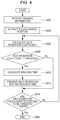
- FIG. 4 is a flowchart illustrating a process example according to the exemplary embodiment.
- step S 402 the drawing information receiving module 110 receives drawing information on a mold.
- step S 404 the pouch-shaped portion extraction module 120 extracts a pouch-shaped portion.
- the process in step S 404 will be discussed in detail later using the flowchart illustrated in the example of FIG. 5 .
- step S 406 the heat reservoir coefficient calculation module 130 calculates a heat reservoir coefficient.
- step S 408 it is determined whether or not “heat reservoir coefficient> threshold” holds true. In the case where “heat reservoir coefficient> threshold” holds true, the process proceeds to step S 410 . Otherwise, the process proceeds to step S 414 .
- step S 410 the molding time calculation module 140 calculates a molding time.
- step S 412 the presentation module 150 presents the heat reservoir site and the molding time.
- step S 414 it is determined whether or not processes for pouch-shaped portions to be targeted are finished. In the case where such processes are finished, the process is ended (step S 499 ). Otherwise, the process returns to step S 406 .
- FIG. 5 is a flowchart illustrating a process example according to the exemplary embodiment.
- a target surface is specified.
- the target surface may be all the surfaces included in the drawing information.
- step S 504 it is determined whether or not an adjacent surface that is adjacent to the target surface is a fillet (curved surface). In the case where the adjacent surface is a fillet, the process proceeds to step S 506 . Otherwise (in the case where the adjacent surface is a flat surface), the process proceeds to step S 512 .
- step S 506 a distance ⁇ from a point A on an edge of the target surface to a point B on an edge of the adjacent surface which is located in the opposite direction from the target surface is calculated.
- step S 508 a point C that is in the normal line direction from the point B is set, and a distance ⁇ from the point A to the point C is calculated.
- the distance from the point B to the point C may be any distance.
- step S 510 the relationship between ⁇ and ⁇ is determined. In the case where “ ⁇ > ⁇ ” holds true, the process proceeds to step S 516 (it is determined that the target surface is a pouch-shaped portion). In the case where “ ⁇ > ⁇ ” does not hold true, the process proceeds to step S 520 (it is determined that the target surface is not a pouch-shaped portion).
- step S 512 an angle between the target surface and the adjacent surface is calculated.
- step S 514 it is determined whether or not the calculated angle is equal to or less than 180 degrees. In the case where the calculated angle is equal to or less than 180 degrees, the process proceeds to step S 516 (it is determined that the target surface is a pouch-shaped portion). Otherwise, the process proceeds to step S 520 (it is determined that the target surface is not a pouch-shaped portion).
- step S 516 the target surface is recognized as a bottom surface.
- step S 518 the adjacent surface is acquired. At this time, the bottom surface and the adjacent surface have been acquired, and thus a pouch-shaped portion has been specified.
- step S 520 it is determined whether or not processes for surfaces to be targeted are finished. In the case where such processes are finished, the process is ended (step S 599 ). Otherwise, the process returns to step S 502 .
- FIGS. 6A to 6C illustrate a process example according to the exemplary embodiment.
- the drawings illustrate a process example for a case where the determination result in step S 504 of the flowchart illustrated in the example of FIG. 5 is “No”. That is, the adjacent surface which is adjacent to the bottom surface is a flat surface as illustrated in the example of FIG. 6A .
- a surface that makes an angle of 180 degrees or less with the adjacent surface is extracted as the bottom surface, and a portion formed by the bottom surface and the adjacent surface is extracted as a pouch-shaped portion.
- an angle 614 made by a target surface 610 and an adjacent surface 612 of a mold 620 is calculated in step S 512 .
- the angle 614 is 270 degrees, and is not equal to or less than 180 degrees.
- a site in a so-called open shape and that includes at least one angle that is not equal to or less than 180 degrees is determined not to be a pouch-shaped portion.
- an angle 654 made by a target surface 650 and an adjacent surface 652 of a mold 660 is calculated in step S 512 .
- the angle 654 is 90 degrees, and is equal to or less than 180 degrees.
- this site is a pouch-shaped portion.
- a site in a so-called closed shape and in which all the angles between the target surface and the adjacent surface are equal to or less than 180 degrees is determined to be a pouch-shaped portion.
- FIGS. 7A and 7B illustrate a process example according to the exemplary embodiment.
- the drawings illustrate a process example for a case where the determination result in step S 504 of the flowchart illustrated in the example of FIG. 5 is “Yes”. That is, the drawings illustrate an example of a case where the adjacent surface which is adjacent to the bottom surface is not a flat surface (but a fillet) as illustrated in the example of FIG. 7A .
- a pouch-shaped portion is extracted using the distance between a point on the boundary between the bottom surface and the adjacent surface and a point on the boundary with the adjacent surface which is located in the opposite direction from the bottom surface.
- a distance ⁇ 718 in a mold 730 from a point 714 on an edge of a target surface 710 to a point 716 on an edge of an adjacent surface 712 located in the opposite direction from the target surface 710 is calculated.
- the point “located in the opposite direction from the target surface 710 ” refers to a point on a side of the adjacent surface 712 that is not a side on which the target surface 710 and the adjacent surface 712 contact each other.
- the point 716 on an edge corresponds to such a point.
- step S 508 a point 722 on a normal line that is in the normal line direction from the point 716 on an edge is set, and a distance ⁇ 724 from the point 714 on an edge to the point 722 on the normal line is calculated.
- the “normal line direction from the point 716 on an edge” refers to the direction of the normal line at the point 716 on an edge and that is not the direction into the mold 730 .
- step S 510 since the relationship “distance ⁇ 718 ⁇ distance ⁇ 724 ” holds true in step S 510 , it is determined that the site is not a pouch-shaped portion.
- a distance ⁇ 758 in a mold 770 from a point 754 on an edge of a target surface 750 to a point 756 on an edge of an adjacent surface 752 located in the opposite direction from the target surface 750 is calculated.
- the point “located in the opposite direction from the target surface 750 ” refers to a point on a side of the adjacent surface 752 that is not a side on which the target surface 750 and the adjacent surface 752 contact each other.
- the point 756 on an edge corresponds to such a point.
- step S 508 a point 762 on a normal line that is in the normal line direction from the point 756 on an edge is set, and a distance ⁇ 764 from the point 754 on an edge to the point 762 on the normal line is calculated.
- the “normal line direction from the point 756 on an edge” refers to the direction of the normal line at the point 756 on an edge and that is not the direction into the mold 770 .
- step S 510 it is determined that the site is not a pouch-shaped portion.
- the distance ( ⁇ ) to an edge of the adjacent surface and the distance ( ⁇ ) to a point in the normal line direction from the edge are compared with each other, and the site is determined as a pouch-shaped portion if ⁇ is the smaller.
- FIG. 8 illustrates a process example according to the exemplary embodiment.
- a surface 810 which is the bottom surface, surfaces 812 , 814 , 816 , etc. (some surfaces are not illustrated in FIG. 8 ) which are fillets that are adjacent to the surface 810 , and a surface 820 that is adjacent to the surface 812 etc. (surfaces that are adjacent to the surfaces 812 , 814 , and 816 ; some surfaces are not illustrated in FIG. 8 ) are acquired in a part 800 .
- the surface 820 is also acquired as a surface that forms a pouch-shaped portion (with the surface 812 serving as the bottom surface and with the surface 820 serving as the adjacent surface) in step S 518 .
- the surfaces 810 , 812 , 814 , 816 , 820 , etc. are acquired as surfaces that form a pouch-shaped portion.
- the total area of such surfaces is determined as a resin contact area a.
- FIG. 9 illustrates a process example according to the exemplary embodiment.
- a pouch-shaped portion is divided into a heat radiation sectional surface 910 and a resin welding surface 920 .
- the heat radiation sectional surface 910 mainly serves as a surface that allows a resin portion to be cooled, and the resin welding surface 920 serves as a portion that stores heat.
- FIGS. 10A and 10B illustrate a process example according to the exemplary embodiment.
- a height 1020 of a pouch-shaped portion from a bottom surface 1010 in a mold 1000 is measured.
- heights 1070 and 1072 of a pouch-shaped portion from a bottom surface 1060 in a mold 1050 are measured. The heights are compared with each other, and the smaller height is determined as the height of the pouch-shaped portion. In this example, the height 1072 is determined as the height of the pouch-shaped portion.
- FIGS. 11A and 11B illustrate a process example according to the exemplary embodiment.
- a surface that forms the pouch-shaped portion (e.g. a sectional surface that is perpendicular to the draft direction) is set from the smallest height, and determined as a heat radiation sectional surface (an example of the sectional area of the pouch-shaped portion).
- the area of the heat radiation sectional surface is defined as a heat radiation sectional area b.
- a heat radiation sectional surface 1110 of a mold 1000 is determined.
- a heat radiation sectional surface 1160 of a mold 1050 is determined.
- the formula (1) indicates the difficulty of heat release. A larger value indicates higher difficulty of heat release.
- the resin contact area a is the total area of the surfaces which form the pouch-shaped portion discussed earlier, which include the bottom surface and the adjacent surfaces.
- Heat reservoir coefficient volume of pouch-shaped portion/heat radiation sectional area b (formula (2))
- the formula (2) indicates the difficulty of heat release. A larger value indicates higher difficulty of heat release.
- the “resin contact area a” in the formula (1) has been replaced with the “volume of pouch-shaped portion”.
- the heat reservoir coefficient and the predetermined threshold are compared with each other to determine whether or not the pouch-shaped portion is a heat reservoir.
- the pouch-shaped portion is determined to be a heat reservoir in the case where the heat reservoir coefficient is equal to or more than the predetermined threshold, and the pouch-shaped portion is determined not to be a heat reservoir in the case where the heat reservoir coefficient is not equal to or more than the predetermined threshold.
- a molding time is calculated using the heat reservoir coefficient.
- a formula that includes the heat reservoir coefficient as a variable e.g. a formula in which the molding time is directly proportional to the heat reservoir coefficient or the like
- a table in which the heat reservoir coefficient and the molding time are correlated with each other may be used.
- a piece of advice that suggests shortening the molding time may be presented.
- a piece of advice that suggests reducing the resin contact area, reducing the depth (height) of the pouch-shaped portion, lowering a rib, etc. may be presented.
- the hardware configuration of a computer that executes a program as the exemplary embodiment is a common computer, specifically a computer that may serve as a personal computer, a server, or the like. That is, as a specific example, the computer includes a CPU 1201 as a processing section (computation section) and a RAM 1202 , a read only memory (ROM) 1203 , and a hard disk (HD) 1204 as storage devices.
- the HD 1204 may be a hard disk drive or a solid state drive (SSD), for example.
- the computer is composed of: the CPU 1201 which executes programs such as the drawing information receiving module 110 , the pouch-shaped portion extraction module 120 , the heat reservoir coefficient calculation module 130 , the molding time calculation module 140 , and the presentation module 150 ; the RAM 1202 which stores the programs and data; the ROM 1203 which stores a program for starting the computer etc.; the HD 1204 which is an auxiliary storage device (which may be a flash memory or the like) that stores CAD data etc.; a receiving device 1206 that receives data on the basis of an operation (including motion, a voice, a line of sight, etc.) performed by the user on a keyboard, a mouse, a touch screen, a microphone, a camera (including a line-of-sight detection camera etc.), or the like; an output device 1205 such as a cathode ray tube (CRT), a liquid crystal display, a speaker, etc.; a communication line interface 1207 for connection with a communication network such as a network interface card; and a bus 12
- the exemplary embodiment discussed earlier implemented by a computer program is implemented by causing a system of the hardware configuration described above to read the computer program as software and causing the software and hardware resources to cooperate with each other.
- the hardware configuration illustrated in FIG. 12 indicates one configuration example.
- the exemplary embodiment is not limited to the configuration illustrated in FIG. 12 , and may have any configuration that may execute the modules described in relation to the exemplary embodiment.
- some of the modules may be constituted by dedicated hardware (such as an application specific integrated circuit (ASIC), for example), some of the modules may be provided in an external system and connected through a communication line, and further plural systems illustrated in FIG. 12 may be connected to each other through a communication line to cooperate with each other.
- ASIC application specific integrated circuit
- the system may be incorporated into not only a personal computer but also a portable information communication device (including a cellular phone, a smartphone, a mobile device, a wearable computer, etc.), an information appliance, a robot, a copier, a facsimile, a scanner, a printer, a multi-function device (image processing device that has the functions of two or more of a scanner, a printer, a copier, a facsimile, etc.), etc.
- a portable information communication device including a cellular phone, a smartphone, a mobile device, a wearable computer, etc.
- an information appliance including a cellular phone, a smartphone, a mobile device, a wearable computer, etc.
- a robot including a copier, a facsimile, a scanner, a printer, a multi-function device (image processing device that has the functions of two or more of a scanner, a printer, a copier, a facsimile, etc.), etc.
- the program described above may be provided as stored in a storage medium, or the program may be provided by a communication unit.
- the program described above may be considered as an invention of a “computer-readable storage medium that stores a program”, for example.
- computer-readable storage medium that stores a program refers to a computer-readable storage medium that stores a program and that is used to install, execute, and distribute the program.
- Examples of the storage medium include digital versatile discs (DVDs) that conform to standards prescribed by the DVD Forum “DVD-R, DVD-RW, DVD-RAM, etc.”, DVDs that conform to standards prescribed by the DVD+RW Alliance “DVD+R, DVD+RW, etc.”, compact discs (CDs) such as read-only memory (CD-ROM), CD recordable (CD-R), and CD rewritable (CD-RW), Blu-ray (registered trademark) discs, magneto-optical (MO) disks, flexible disks (FDs), magnetic tapes, hard disks, read-only memories (ROMs), electrically erasable reprogrammable read-only memories (EEPROMs (registered trademark)), flash memories, random-access memories (RAMs), and SD (Secure Digital) memory cards.
- DVDs digital versatile discs
- DVDs digital versatile discs
- DVDs digital versatile discs
- DVDs digital versatile discs
- DVDs digital versatile discs
- DVDs that conform to standards prescribed by
- a part or all of the program described above may be saved, distributed, etc. as stored in the storage medium.
- a part or all of the program may be transferred through communication using a transfer medium such as a wired network, a wireless communication network, or a combination thereof used as a local area network (LAN), a metropolitan area network (MAN), a wide area network (WAN), the Internet, an intranet, an extranet, or the like, or may be carried over a carrier wave.
- program described above may be a part or all of another program, or may be stored in a storage medium together with another program.
- the program may be stored as divided in plural storage media.
- the program may be compressed, encrypted, or stored in any form as long as the program may be restored.
Landscapes
- Engineering & Computer Science (AREA)
- Physics & Mathematics (AREA)
- Theoretical Computer Science (AREA)
- Geometry (AREA)
- General Physics & Mathematics (AREA)
- Computer Hardware Design (AREA)
- Evolutionary Computation (AREA)
- General Engineering & Computer Science (AREA)
- Computational Mathematics (AREA)
- Mathematical Analysis (AREA)
- Mathematical Optimization (AREA)
- Pure & Applied Mathematics (AREA)
- Injection Moulding Of Plastics Or The Like (AREA)
- Moulds For Moulding Plastics Or The Like (AREA)
- Architecture (AREA)
- Software Systems (AREA)
Abstract
Description
Heat reservoir coefficient=resin contact area a/heat radiation sectional area b (formula (1))
Heat reservoir coefficient=volume of pouch-shaped portion/heat radiation sectional area b (formula (2))
Claims (6)
Applications Claiming Priority (3)
| Application Number | Priority Date | Filing Date | Title |
|---|---|---|---|
| JP2017-146017 | 2017-07-28 | ||
| JPJP2017-146017 | 2017-07-28 | ||
| JP2017146017A JP6988232B2 (en) | 2017-07-28 | 2017-07-28 | Information processing equipment and information processing programs |
Publications (2)
| Publication Number | Publication Date |
|---|---|
| US20190034559A1 US20190034559A1 (en) | 2019-01-31 |
| US11036895B2 true US11036895B2 (en) | 2021-06-15 |
Family
ID=65037958
Family Applications (1)
| Application Number | Title | Priority Date | Filing Date |
|---|---|---|---|
| US15/954,606 Active 2039-10-27 US11036895B2 (en) | 2017-07-28 | 2018-04-17 | Information processing apparatus for determining a heat reservoir in a molding process |
Country Status (2)
| Country | Link |
|---|---|
| US (1) | US11036895B2 (en) |
| JP (1) | JP6988232B2 (en) |
Citations (4)
| Publication number | Priority date | Publication date | Assignee | Title |
|---|---|---|---|---|
| JPH04334419A (en) | 1991-05-10 | 1992-11-20 | Olympus Optical Co Ltd | Injection molding die |
| JP2000190371A (en) | 1998-12-25 | 2000-07-11 | Olympus Optical Co Ltd | Mold |
| US20160167295A1 (en) * | 2014-12-12 | 2016-06-16 | The Procter & Gamble Company | Method of predicing injection molding cycle time |
| US20170160726A1 (en) * | 2015-12-07 | 2017-06-08 | Dassault Systemes | Detecting cut-outs |
Family Cites Families (3)
| Publication number | Priority date | Publication date | Assignee | Title |
|---|---|---|---|---|
| JP3078178B2 (en) * | 1994-07-05 | 2000-08-21 | 積水化学工業株式会社 | Optimizing cooling piping for injection molds |
| JP5413532B1 (en) * | 2013-06-20 | 2014-02-12 | 富士ゼロックス株式会社 | PROJECTION DETECTION DEVICE, PROJECTION DETECTION SYSTEM, AND PROJECTION DETECTION PROGRAM |
| US20170021570A1 (en) * | 2015-03-24 | 2017-01-26 | Technology Research Association For Future Additive Manufacturing | Three-dimensional fabricating system, method of manufacturing three-dimensional fabricated object, information processing apparatus, method of generating structure for heat dissipation of three-dimensional fabricated object, and program for generating structure for heat dissipation of three-dimensional fabricated object |
-
2017
- 2017-07-28 JP JP2017146017A patent/JP6988232B2/en active Active
-
2018
- 2018-04-17 US US15/954,606 patent/US11036895B2/en active Active
Patent Citations (4)
| Publication number | Priority date | Publication date | Assignee | Title |
|---|---|---|---|---|
| JPH04334419A (en) | 1991-05-10 | 1992-11-20 | Olympus Optical Co Ltd | Injection molding die |
| JP2000190371A (en) | 1998-12-25 | 2000-07-11 | Olympus Optical Co Ltd | Mold |
| US20160167295A1 (en) * | 2014-12-12 | 2016-06-16 | The Procter & Gamble Company | Method of predicing injection molding cycle time |
| US20170160726A1 (en) * | 2015-12-07 | 2017-06-08 | Dassault Systemes | Detecting cut-outs |
Non-Patent Citations (3)
| Title |
|---|
| Martin et al. "A CAD/CAE-integrated injection mold design system for plastic products". Int J Adv Manuf Technol (2012) 63: pp. 596-607. (Year: 2012). * |
| Sunil et al. ("Automatic recognition of features from freeform surface CAD models". Computer-Aided Design 40 (2008) 502-517. (Year: 2008). * |
| Xu et al. "Recognition of rough machining features in 2 1/2 D components". Computer-Aided Design, vol. 30, No. 7, pp. 503-516, 1998. (Year: 1998). * |
Also Published As
| Publication number | Publication date |
|---|---|
| JP6988232B2 (en) | 2022-01-05 |
| US20190034559A1 (en) | 2019-01-31 |
| JP2019028632A (en) | 2019-02-21 |
Similar Documents
| Publication | Publication Date | Title |
|---|---|---|
| US10510159B2 (en) | Information processing apparatus, control method for information processing apparatus, and non-transitory computer-readable storage medium | |
| CN109961406A (en) | Image processing method and device and terminal equipment | |
| KR20130049091A (en) | Apparatus and method for detecting error of lesion contour, apparatus and method for correcting error of lesion contour and, apparatus for insecting error of lesion contour | |
| CN107423409A (en) | A kind of image processing method, image processing apparatus and electronic equipment | |
| JP2013500536A5 (en) | ||
| CN108027884A (en) | Optimization object detects | |
| CN113030990A (en) | Fusion ranging method and device for vehicle, ranging equipment and medium | |
| CN115830065B (en) | Image-based speed determination method, device, equipment and storage medium | |
| CN111210506B (en) | Three-dimensional restoration method, system, terminal equipment and storage medium | |
| US10089764B2 (en) | Variable patch shape synthesis | |
| JP7124957B2 (en) | Image processing system, estimation device, processing method and program | |
| CN107240104B (en) | Point cloud data segmentation method and terminal | |
| CN110008823B (en) | Vehicle damage assessment method and device and electronic equipment | |
| CN106991376B (en) | Depth information-combined side face verification method and device and electronic device | |
| US11036895B2 (en) | Information processing apparatus for determining a heat reservoir in a molding process | |
| US9651937B2 (en) | Computing device and method for compensating coordinates of position device | |
| JP5737387B2 (en) | Image processing device | |
| JP2014071895A (en) | Object dividing apparatus and method | |
| CN106407888A (en) | Fingerprint identification method, device and mobile terminal | |
| US20190034987A1 (en) | Information processing apparatus | |
| JP7091809B2 (en) | Information processing equipment and information processing programs | |
| JP6852487B2 (en) | Information processing equipment and information processing programs | |
| JP6031936B2 (en) | Image processing apparatus and image processing program | |
| JP6852489B2 (en) | Information processing equipment and information processing programs | |
| JP6897208B2 (en) | Information processing equipment and information processing programs |
Legal Events
| Date | Code | Title | Description |
|---|---|---|---|
| FEPP | Fee payment procedure |
Free format text: ENTITY STATUS SET TO UNDISCOUNTED (ORIGINAL EVENT CODE: BIG.); ENTITY STATUS OF PATENT OWNER: LARGE ENTITY |
|
| AS | Assignment |
Owner name: FUJI XEROX CO., LTD., JAPAN Free format text: ASSIGNMENT OF ASSIGNORS INTEREST;ASSIGNORS:SHIRABE, YOSHITOMO;YAMAKAWA, YASUAKI;YOSHIZUKA, MASANORI;SIGNING DATES FROM 20180201 TO 20180202;REEL/FRAME:045628/0124 |
|
| STPP | Information on status: patent application and granting procedure in general |
Free format text: DOCKETED NEW CASE - READY FOR EXAMINATION |
|
| STPP | Information on status: patent application and granting procedure in general |
Free format text: NON FINAL ACTION MAILED |
|
| STPP | Information on status: patent application and granting procedure in general |
Free format text: NOTICE OF ALLOWANCE MAILED -- APPLICATION RECEIVED IN OFFICE OF PUBLICATIONS |
|
| STPP | Information on status: patent application and granting procedure in general |
Free format text: PUBLICATIONS -- ISSUE FEE PAYMENT RECEIVED |
|
| STPP | Information on status: patent application and granting procedure in general |
Free format text: PUBLICATIONS -- ISSUE FEE PAYMENT VERIFIED |
|
| STCF | Information on status: patent grant |
Free format text: PATENTED CASE |
|
| AS | Assignment |
Owner name: FUJIFILM BUSINESS INNOVATION CORP., JAPAN Free format text: CHANGE OF NAME;ASSIGNOR:FUJI XEROX CO., LTD.;REEL/FRAME:056628/0192 Effective date: 20210401 |
|
| AS | Assignment |
Owner name: FUJIFILM BUSINESS INNOVATION CORP., JAPAN Free format text: CORRECTIVE ASSIGNMENT TO CORRECT THE ADDRESS OF THE ASSIGNEE PREVIOUSLY RECORDED ON REEL 056628 FRAME 0192. ASSIGNOR(S) HEREBY CONFIRMS THE CHANGE OF NAME;ASSIGNOR:FUJI XEROX CO., LTD.;REEL/FRAME:057391/0364 Effective date: 20210401 |
|
| MAFP | Maintenance fee payment |
Free format text: PAYMENT OF MAINTENANCE FEE, 4TH YEAR, LARGE ENTITY (ORIGINAL EVENT CODE: M1551); ENTITY STATUS OF PATENT OWNER: LARGE ENTITY Year of fee payment: 4 |