US11032547B2 - Image encoding apparatus, control method thereof, and non-transitory computer-readable storage medium - Google Patents
Image encoding apparatus, control method thereof, and non-transitory computer-readable storage medium Download PDFInfo
- Publication number
- US11032547B2 US11032547B2 US16/600,817 US201916600817A US11032547B2 US 11032547 B2 US11032547 B2 US 11032547B2 US 201916600817 A US201916600817 A US 201916600817A US 11032547 B2 US11032547 B2 US 11032547B2
- Authority
- US
- United States
- Prior art keywords
- unit
- plane
- encoding
- gain
- component
- Prior art date
- Legal status (The legal status is an assumption and is not a legal conclusion. Google has not performed a legal analysis and makes no representation as to the accuracy of the status listed.)
- Active
Links
Images


Classifications
-
- H—ELECTRICITY
- H04—ELECTRIC COMMUNICATION TECHNIQUE
- H04N—PICTORIAL COMMUNICATION, e.g. TELEVISION
- H04N19/00—Methods or arrangements for coding, decoding, compressing or decompressing digital video signals
- H04N19/10—Methods or arrangements for coding, decoding, compressing or decompressing digital video signals using adaptive coding
- H04N19/102—Methods or arrangements for coding, decoding, compressing or decompressing digital video signals using adaptive coding characterised by the element, parameter or selection affected or controlled by the adaptive coding
- H04N19/13—Adaptive entropy coding, e.g. adaptive variable length coding [AVLC] or context adaptive binary arithmetic coding [CABAC]
-
- H—ELECTRICITY
- H04—ELECTRIC COMMUNICATION TECHNIQUE
- H04N—PICTORIAL COMMUNICATION, e.g. TELEVISION
- H04N19/00—Methods or arrangements for coding, decoding, compressing or decompressing digital video signals
- H04N19/85—Methods or arrangements for coding, decoding, compressing or decompressing digital video signals using pre-processing or post-processing specially adapted for video compression
-
- H—ELECTRICITY
- H04—ELECTRIC COMMUNICATION TECHNIQUE
- H04N—PICTORIAL COMMUNICATION, e.g. TELEVISION
- H04N19/00—Methods or arrangements for coding, decoding, compressing or decompressing digital video signals
- H04N19/10—Methods or arrangements for coding, decoding, compressing or decompressing digital video signals using adaptive coding
- H04N19/102—Methods or arrangements for coding, decoding, compressing or decompressing digital video signals using adaptive coding characterised by the element, parameter or selection affected or controlled by the adaptive coding
- H04N19/117—Filters, e.g. for pre-processing or post-processing
-
- H—ELECTRICITY
- H04—ELECTRIC COMMUNICATION TECHNIQUE
- H04N—PICTORIAL COMMUNICATION, e.g. TELEVISION
- H04N19/00—Methods or arrangements for coding, decoding, compressing or decompressing digital video signals
- H04N19/10—Methods or arrangements for coding, decoding, compressing or decompressing digital video signals using adaptive coding
- H04N19/134—Methods or arrangements for coding, decoding, compressing or decompressing digital video signals using adaptive coding characterised by the element, parameter or criterion affecting or controlling the adaptive coding
- H04N19/146—Data rate or code amount at the encoder output
- H04N19/147—Data rate or code amount at the encoder output according to rate distortion criteria
-
- H—ELECTRICITY
- H04—ELECTRIC COMMUNICATION TECHNIQUE
- H04N—PICTORIAL COMMUNICATION, e.g. TELEVISION
- H04N19/00—Methods or arrangements for coding, decoding, compressing or decompressing digital video signals
- H04N19/10—Methods or arrangements for coding, decoding, compressing or decompressing digital video signals using adaptive coding
- H04N19/134—Methods or arrangements for coding, decoding, compressing or decompressing digital video signals using adaptive coding characterised by the element, parameter or criterion affecting or controlling the adaptive coding
- H04N19/154—Measured or subjectively estimated visual quality after decoding, e.g. measurement of distortion
-
- H—ELECTRICITY
- H04—ELECTRIC COMMUNICATION TECHNIQUE
- H04N—PICTORIAL COMMUNICATION, e.g. TELEVISION
- H04N19/00—Methods or arrangements for coding, decoding, compressing or decompressing digital video signals
- H04N19/10—Methods or arrangements for coding, decoding, compressing or decompressing digital video signals using adaptive coding
- H04N19/169—Methods or arrangements for coding, decoding, compressing or decompressing digital video signals using adaptive coding characterised by the coding unit, i.e. the structural portion or semantic portion of the video signal being the object or the subject of the adaptive coding
- H04N19/182—Methods or arrangements for coding, decoding, compressing or decompressing digital video signals using adaptive coding characterised by the coding unit, i.e. the structural portion or semantic portion of the video signal being the object or the subject of the adaptive coding the unit being a pixel
-
- H—ELECTRICITY
- H04—ELECTRIC COMMUNICATION TECHNIQUE
- H04N—PICTORIAL COMMUNICATION, e.g. TELEVISION
- H04N19/00—Methods or arrangements for coding, decoding, compressing or decompressing digital video signals
- H04N19/10—Methods or arrangements for coding, decoding, compressing or decompressing digital video signals using adaptive coding
- H04N19/169—Methods or arrangements for coding, decoding, compressing or decompressing digital video signals using adaptive coding characterised by the coding unit, i.e. the structural portion or semantic portion of the video signal being the object or the subject of the adaptive coding
- H04N19/186—Methods or arrangements for coding, decoding, compressing or decompressing digital video signals using adaptive coding characterised by the coding unit, i.e. the structural portion or semantic portion of the video signal being the object or the subject of the adaptive coding the unit being a colour or a chrominance component
-
- H—ELECTRICITY
- H04—ELECTRIC COMMUNICATION TECHNIQUE
- H04N—PICTORIAL COMMUNICATION, e.g. TELEVISION
- H04N19/00—Methods or arrangements for coding, decoding, compressing or decompressing digital video signals
- H04N19/60—Methods or arrangements for coding, decoding, compressing or decompressing digital video signals using transform coding
- H04N19/625—Methods or arrangements for coding, decoding, compressing or decompressing digital video signals using transform coding using discrete cosine transform [DCT]
Definitions
- the present invention relates to RAW image data encoding technology.
- Image capturing apparatuses such as digital cameras or electronic devices having image capturing functions carry out what is known as developing processing.
- raw image information a RAW image
- debayering demosaicing
- signals constituted by luma and chroma components each signal is then subjected to noise removal, optical distortion correction, image optimization, and the like.
- the developed luma and chroma signals are then compressed, encoded, and recorded into a recording medium.
- a RAW image is a type of data that keeps correction, degradation, and the like to a minimum. Advanced users therefore prefer to use RAW images for editing after shooting.
- RAW images contain very large amounts of data, and it would therefore be useful to suppress the amount of data so that as many images as possible can be recorded into a recording medium.
- the data amounts of RAW images are therefore suppressed by compressing the RAW images.
- compressing an image may harm the image quality.
- Japanese Patent Laid-Open No. 2017-208810 discloses a configuration in which RAW data is subjected to white balancing, after which each color component is compressed and encoded.
- the present invention provides a technique for suppressing color shifts caused by quantization parameters used to encode RAW image data.
- an image encoding apparatus that encodes a frame obtained by an image capturing unit as RAW image data
- the apparatus comprising: a calculating unit that finds a color temperature of the RAW image data of a target frame which is to be encoded, and calculates a gain value for each of color components in order to apply white balancing to the RAW image data; a generating unit that generates a plurality of planes, each plane constituted by data of a single color component, from the RAW image data in the target frame; an adjusting unit that adjusts the white balance of each plane obtained by the generating unit on the basis of the gain calculated by the calculating unit; an encoding unit that encodes each plane by frequency-transforming, quantizing, and encoding each plane; and a control unit that, when each plane of the target frame is encoded by the encoding unit, switches between encoding the plurality of planes generated by the generating unit or encoding the plurality of planes adjusted by the adjusting unit, on the basis
- color shifts caused by quantization parameters used when encoding RAW image data can be suppressed.
- FIG. 1 is a block diagram illustrating an example of the configuration of an image encoding apparatus according embodiments.
- FIG. 2 is a descriptive diagram illustrating a pixel array.
- FIG. 3 is a block diagram illustrating a RAW compression encoding unit.
- FIG. 4 is a sub-band formation diagram illustrating decomposition level 3 of a discrete wavelet transform (DWT).
- DWT discrete wavelet transform
- FIG. 5 is a flowchart illustrating an example of processing by a WB control unit.
- FIGS. 6A and 6B are histograms illustrating image data according to embodiments.
- FIGS. 7A and 7B are graphs illustrating cumulative frequencies of wavelet coefficients for each of color components.
- FIG. 8 is a diagram illustrating an example of a file format.
- FIG. 9 is a diagram illustrating an example of the data structure of a main header part.
- FIG. 10 is a diagram illustrating an example of the data structure of a plane header part.
- FIG. 11 is a diagram illustrating an example of the data structure of a sub-band header part.
- FIG. 12 is a block diagram illustrating a RAW compression encoding unit according to a second embodiment.
- FIG. 13 is a flowchart illustrating an example of processing by a second WB control unit.
- FIG. 14 is a diagram illustrating an example of the data structure of a main header part according to the second embodiment.
- FIG. 15 is a diagram illustrating a relationship between color temperature and gain according to a third embodiment.
- FIG. 16 is a diagram illustrating a frequency distribution for each of color components after gain adjustment according to the third embodiment.
- FIG. 17 is a graph illustrating cumulative frequencies of wavelet coefficients for each of color components according to the third embodiment.
- FIG. 1 is a block diagram illustrating the main components of an image capturing apparatus 100 ) according to a first embodiment.
- the image capturing apparatus 100 includes an imaging optical unit 101 , an imaging sensor 102 , a sensor signal processing unit 103 , a WB gain calculating unit 104 , a RAW compression encoding unit 105 , a buffer 106 , a recording data control unit 107 , a control unit 150 , and an operation unit 151 .
- an optical image of a subject of which an image is to be captured is input through the imaging optical unit 101 and formed on the imaging sensor 102 .
- the imaging sensor 102 converts the intensity of light, which passes through red (R), green (G), and blue (B) color filters arranged on a pixel-by-pixel basis, into electrical signals. Note that the imaging sensor 102 is assumed to capture images at a speed of, for example, 30 frames per second.
- FIG. 2 illustrates an example of the color filters arranged on the imaging sensor 102 .
- red (R), green (G), and blue (B) are arranged in mosaic form on a pixel-by-pixel basis, with one red pixel, one blue pixel, and two green pixels constituting a set of four, i.e., 2 ⁇ 2, pixels, which are arranged in a regular manner.
- This pixel arrangement is typically called a Bayer array.
- the electrical signal obtained by the imaging sensor 102 is converted into digital image data and supplied to the sensor signal processing unit 103 .
- the sensor signal processing unit 103 then carries out pixel restoration processing.
- the restoration processing includes processing for interpolating a pixel to be restored using the values of the surrounding pixels, subtracting a predetermined offset value, and so on for missing or unreliable pixels in the imaging sensor 102 .
- the image data output from the sensor signal processing unit 103 will be called RAW image data, which indicates a raw (undeveloped) image still in the Bayer array format.
- the RAW image data is supplied to the WB gain calculating unit 104 and the RAW compression encoding unit 105 .
- the WB gain calculating unit 104 adjusts the white balance using the green (G) component of the input RAW image data as a reference, and thus calculates a gain value by which to multiply the red (R) and blue (B) components.
- the gain value can be calculated for each color component on the basis of the color temperature.
- the WB gain calculating unit 104 supplies the calculated WB gain value to the RAW compression encoding unit 105 .
- the RAW compression encoding unit 105 generates data of a plurality of sub-bands by subjecting the RAW image data input from the sensor signal processing unit 103 to a wavelet transform, quantizes and entropy-encodes that data, and then stores compressed and encoded data in the buffer 106 .
- FIG. 3 is a block diagram illustrating the RAW compression encoding unit 105 according to the embodiment. Processing carried out by the RAW compression encoding unit 105 will be described in detail next with reference to FIG. 3 .
- the RAW compression encoding unit 105 includes: input terminals 301 and 312 ; a plane division unit 302 ; a switch 303 ; a discrete wavelet transform unit 304 ; a quantizing unit 305 ; an entropy encoding unit 306 ; an output terminal 307 ; a WB gain computation unit 308 ; a quantization control unit 309 ; a code amount calculating unit 310 ; and a WB control unit 311 .
- RAW image data input from the input terminal 301 is supplied to the plane division unit 302 .
- the plane division unit 302 converts the input RAW image data into four planes, each of which is constituted by pixels of a single color component.
- the RAW image data is, as mentioned earlier, a collection of pixels in a Bayer array, and thus there are twice as many green component pixels as there are red (or blue) components pixels. Accordingly, the green pixel components adjacent to the red component pixels in the horizontal direction are defined as G1, and the green pixel components adjacent to the blue component pixels in the horizontal direction are defined as G2.
- the plane division unit 302 From the input RAW image data, the plane division unit 302 generates a G1 plane constituted only by G1 component pixels, a G2 plane constituted only by G2 component pixels, an R plane constituted only by R component pixels, and a B plane constituted only by B component pixels.
- the four pieces of plane data generated by the plane division unit 302 are supplied to the switch 303 .
- the switch 303 receives a selection signal indicating whether or not to apply white balancing from the WB control unit 311 , and outputs to either the discrete wavelet transform unit 304 or the WB gain computation unit 308 as an output destination.
- a selection signal indicating that white balancing is not to be applied has been received
- the switch 303 supplies the input plane data to the discrete wavelet transform unit 304 through a terminal A.
- the switch 303 supplies the input plane data to the WB gain computation unit 308 through a terminal B.
- the WB control unit 311 uses the WB gain value calculated by the WB gain calculating unit 104 , obtained from the input terminal 312 , and quantization parameters Qp from the quantization control unit 309 (mentioned later), to determine the selection signal for the switch 303 (details will be described later).
- the discrete wavelet transform unit 304 frequency-transforms the input plane data to obtain transform coefficients for a plurality of frequency ranges (sub-bands).
- FIG. 4 is a sub-band formation diagram illustrating decomposition level 3 , obtained when vertical and horizontal filtering using a discrete wavelet transform (DWT) are carried out three times each.
- the present embodiment assumes that the discrete wavelet transform unit 304 carries out the DWT three times to generate sub-bands at decomposition level 3 .
- DWT discrete wavelet transform
- the DWT decomposes a frequency band into multiple bands by applying a filter in both the vertical and horizontal directions.
- the decomposition level can be increased by recursively applying DWTs to the low-frequency sub-bands generated through the stated transform, which increases the fineness of the frequency decomposition, as illustrated in FIG. 4 .
- “L” and “H” indicate low and high frequencies, respectively. In terms of the order thereof, the former indicates the band resulting from the horizontal filtering, and the latter indicates the band resulting from the vertical filtering.
- the number after “Lv” indicates the DWT decomposition level.
- “LL” indicates the lowest-frequency sub-band.
- the discrete wavelet transform unit 304 carries out this discrete wavelet transform processing, and supplies the obtained transform coefficient data to the quantizing unit 305 on a sub-band-by-sub-band basis.
- the quantizing unit 305 uses the quantization parameters Qp generated by the quantization control unit 309 to quantize the transform coefficients on a transform coefficient-by-transform coefficient basis.
- the quantization parameters Qp are parameters in which a higher value contributes more to a reduction in the code amount, but which also involve a drop in image quality caused by an increase in quantization error.
- the entropy encoding unit 306 generates encoded data by entropy-encoding the transform coefficient data that has been quantized by the quantizing unit 305 .
- the entropy encoding unit 306 outputs the generated encoded data to the buffer 106 through the output terminal 307 , as well as to the code amount calculating unit 310 .
- the code amount calculating unit 310 calculates a code amount on a sub-band-by-sub-band basis, and a code amount on a picture-by-picture basis, from the input encoded data. The code amount calculating unit 310 then supplies information indicating the calculated code amounts to the quantization control unit 309 .
- the quantization control unit 309 calculates a picture target code amount and a sub-band target code amount, and generates base quantization parameters Qpbase at which each sub-band will be the optimal sub-band in the next picture.
- preliminary encoding may first be carried out on the image before recording, and the above-described processing may then be carried out.
- the present embodiment will describe the base quantization parameters Qpbase as quantization parameters used for sub-band IvIHL indicated in FIG. 4 .
- the quantization parameters for the other sub-bands are calculated from the base quantization parameters Qpbase.
- FIG. 5 is a flowchart illustrating a processing sequence executed by the WB control unit 311 .
- the details of the processing by the WB control unit 311 will be described next with reference to FIG. 5 .
- the WB control unit 311 starts the processing in step S 501 .
- step S 502 the WB control unit 311 obtains WB gain information for the RAW image data of a current frame to be encoded, from the WB gain calculating unit 104 through the input terminal 312 .
- the WB gain information has a different gain value for each color component.
- the gain values for R. G, and B are represented by Gain_R, Gain_G, and Gain_B, respectively.
- G (green) is taken as a reference, and Gain_G is fixed at 1.
- the R and B gain values are values relative to the G gain value.
- the WB control unit 311 need only obtain Gain_R and Gain_B.
- step S 503 the WB control unit 311 obtains the base quantization parameters for the plane Lv 1 HL of each color component, among the quantization parameters output by the quantization control unit 309 .
- the base quantization parameters for these are represented by Qbase_R, Qbase_G1, Qbase_G2, and Qbase_B, respectively. Note that these base quantization parameters are parameters from when encoding the frame immediately before the frame of interest being encoded.
- step S 504 the WB control unit 311 calculates thresholds Qth_R and Qth_B at which the image quality can be guaranteed, for each of the red (R) and blue (B) color components. Desired quantization parameters are set for these thresholds in advance. Because green (G) is used as the reference, a threshold Qth_G for green (G) serves as a reference value for the thresholds of the other components. The WB control unit 311 then calculates the red (R) and blue (B) thresholds according to the following equations (1) and (2).
- Qth _ R Qth _ G /Gain_ R (1)
- Qth _ B Qth _ G /Gain_ B (2)
- step S 505 the WB control unit 311 determines whether or not the image quality for each of the color components is within a guaranteed range, by comparing the thresholds calculated for each color component with the corresponding gain value. Specifically, the WB control unit 311 determines whether or not the following equations (3) to (6) are satisfied.
- the WB control unit 311 determines whether each input plane is within the range where the image quality is guaranteed. Accordingly, the WB control unit 311 moves the processing to step S 506 , where the switch 303 outputs a control signal for selecting the terminal A. In other words, as a result, the picture of interest is encoded without carrying out any WB processing.
- the WB control unit 311 determines that the image quality is outside the guaranteed range. Accordingly, the WB control unit 311 moves the processing to step S 507 , w % here the switch 303 outputs a control signal for selecting the terminal B. As a result, the WB gain computation unit 308 adjusts the gain for the input planes of each component, according to the gain values computed by the WB gain calculating unit 104 , and then supplies the adjusted planes to the discrete wavelet transform unit 304 .
- step S 508 the WB control unit 311 ends the present processing. Because G1 and G2 indicate the same color green, one of equations (4) and (5) may be excluded from the determination.
- FIG. 6A is a histogram of each of the RGB planes in a given one frame of RAW image data.
- FIG. 6B is a histogram of each of the RGB planes after the white balance processing has been carried out.
- FIG. 7A is a graph indicating the cumulative frequencies of the wavelet coefficients for the R, G1 (which is the same as G2), and B planes indicated in FIG. 6A .
- the R plane has a narrower range than the other planes.
- the wavelet coefficient of the R plane has a lower value, which means that the cumulative frequency of the wavelet coefficient approaches a maximum value more quickly than the other planes.
- This cumulative frequency graph can be estimated from the range of a plane by using the histogram of that plane.
- a broken line is present at the location of 15% along the horizontal axis. If the bit width of the input data is 10 bits and the quantization coefficient at the location of the broken line is 10, dividing the wavelet coefficient data by 10 and rounding the resultant off results in a quotient of 0 for wavelet coefficients less than or equal to 9. Accordingly, even if inverse quantization is carried out, the wavelet coefficients will be 0 even after the inverse quantization. However, it is assumed that the quantization coefficients and the quantization parameters are in a 1-to-1 relationship, and that the quantization coefficient is equivalent to the quotient.
- the input image has a high level of encoding difficulty, it is necessary to increase the quantization parameters and suppress the code amount in order to suppress the code amount to a set amount. Accordingly, if the gain is different for each of the color components as illustrated in FIG. 6A , the hue will change from location to location, which leads to an increased amount of image quality degradation caused by color shifts.
- FIG. 7B is a graph illustrating a state after white balancing by multiplying the color components illustrated in FIG. 7A by gain values. Carrying out the white balancing makes it possible to suppress situations where the wavelet coefficient is 0 only for specific color components, which in turn makes it possible to suppress changes in the hue.
- the gain values are multiplied.
- the value is clipped at an upper limit value.
- the white balancing therefore involves a trade-off, but because the amount of image degradation is extremely small compared to when the wavelet coefficient is 0, the hue changes, and color shifting occurs, that image degradation is almost impossible to notice.
- the recording data control unit 107 generates predetermined header information, including information necessary for decoding, for the encoded data stored in the buffer 106 , adds that information to the following encoded data, and outputs the resulting data as a file from an output terminal 108 .
- the output destination is not particularly limited, and may be a non-volatile storage medium such as a memory card, for example.
- the header information generated by the recording data control unit 107 and the data format thereof, will be described next.
- FIG. 8 illustrates an example of the file format.
- the file is divided into a header part and a data part, and the header part includes a main header part and a sub header part.
- FIG. 9 illustrates the data structure of the main header part.
- an identification number the image size, the image bit width, the WB gain value, the wavelet transform decomposition level, the header size, a thumbnail image, and an address and data size of the data part are included.
- the identification number in FIG. 9 is a number indicating the main header, and the other headers are also recorded so that they can be identified using this identification number. The identification number therefore differs from header to header.
- the switch 303 selects the terminal A and no white balancing is applied, the value output by the WB gain calculating unit 104 is recorded in the header. This is done so that the value can be usefully applied as an indication value for WB processing when the user develops or edits the image later.
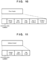
- FIG. 10 illustrates the data structure of a plane header part.
- an identification number, a header state, the header size, the address and data size of the data part, a sub-band number, and a sub-band header are recorded.
- FIG. 11 illustrates the data structure of the sub-band header part.
- an identification number a header state, the header size, and the address and data size of the data part are recorded.
- compressed and encoded data can be developed appropriately regardless of whether or not white balancing has been applied.
- the white balance processing is carried out only when white balancing is necessary, which makes it possible to suppress image quality degradation caused by color shifts or the like regardless of the input image.
- the operation unit 151 illustrated in FIG. 1 is configured so that the user can turn the automatic white balance changes on or off.
- the control unit 150 outputs control signals so that the white balance is changed only when the automatic white balance changes have been turned on by the user, and the white balance is not changed when the automatic white balance changes have been turned off by the user.
- a second embodiment will now be described.
- the apparatus configuration according to the present second embodiment is the same as that illustrated in FIG. 1 and described in the first embodiment.
- the processing carried out by the RAW compression encoding unit 105 , and the data recorded to a recording medium group 107 , according to the present second embodiment are different from in the first embodiment, and will therefore be described in detail.
- FIG. 12 is a block diagram illustrating the configuration of the RAW compression encoding unit 105 according to the present second embodiment. Processing units that are the same as those illustrated in FIG. 3 and described earlier in the first embodiment are given the same reference signs, and will not be described.
- FIG. 12 differs from FIG. 3 in that a plane transform unit 1213 has been added, and the WB control unit 311 of FIG. 3 has been replaced with a second WB control unit 1214 .
- the plane division unit 302 inputs Bayer array RAW image data through the input terminal 301 .
- the plane division unit 302 then divides the input RAW image data into each of the color components.
- the number of pixels in the green (G) component is twice the number of pixels in each of the red (R) and blue (B) components. Accordingly, the green adjacent to red (R) in the horizontal direction is defined as G1, and the green adjacent to blue (B) in the horizontal direction is defined as G2.
- the plane division unit 302 divides the input RAW image data into four planes, namely R, G1, G2, and B planes, and outputs the resulting plane data to the switch 303 .
- the switch 303 sets the output destination of each plane to either the plane transform unit 1213 or the WB gain computation unit 308 , under the control of the second WB control unit 1214 .
- the plane transform unit 1213 being selected as the output destination by the switch 303 means that the planes will not pass through the WB gain computation unit 308 , and will therefore not be subjected to white balance correction processing.
- the WB gain computation unit 308 is selected as the output destination by the switch 303 , each plane is multiplied by gain value by the WB gain computation unit 308 , and is then supplied to the plane transform unit 1213 .
- the second WB control unit 1214 controls the selection by the switch 303 in accordance with a WB gain value calculated by the WB gain calculating unit 104 and which is input from the parameter input terminal 312 , and the quantization parameters Qp output by the quantization control unit 309 , which will be described later (this control will be described in detail later).
- the plane transform unit 1213 calculates a luma component Y and three chroma components C1, C2, and C3 in accordance with the following equations (7) to (10), and outputs those components.
- Y ( R+G 1+ G 2+ B )/4 (7)
- C 1 R ⁇ G 1 (8)
- C 2 B ⁇ G 2 (9)
- C 3 ( R+G 1)/2 ⁇ ( B+G 2)/2 (10)
- the plane transform unit 1213 generates Y, C1, C2, and C3 planes, each of which is constituted by a single component, and outputs those planes to the discrete wavelet transform unit 304 .
- the four planes to be encoded according to the present second embodiment are the Y plane, indicating a luma component, and the C1, C2, and C3 planes, indicating chroma components.
- FIG. 13 is a flowchart illustrating the details of the processing carried out by the second WB control unit 1214 .
- the processing carried out by the second WB control unit 1214 will be described next with reference to FIG. 13 .
- the second WB control unit 1214 starts the processing in step S 1301 .
- the second WB control unit 1214 obtains the WB gain information output by the WB gain calculating unit 104 .
- the WB gain information has a different gain value for each color component.
- the gain values for red (R), green (G), and blue (B) are represented by Gain_R, Gain_G, and Gain_B, respectively.
- G green
- Gain_B gain_B
- step S 1303 the second WB control unit 1214 takes Lv 1 HL of each plane as the base quantization parameters, among the quantization parameters output by the quantization control unit 309 , and obtains Qbase_Y.
- the second WB control unit 1214 calculates thresholds Qth_Y, Qth_C1, Qth_C2, and Qth_C3 at which the image quality can be guaranteed, for the luma component Y and the chroma components C1, C2, and C3, respectively. Desired quantization parameters Qth_Ybase, Qth_C1base, Qth_C2base, and Qth_C3base are set for these thresholds in advance. The second WB control unit 1214 then finds the thresholds for the luma component Y and the chroma components C1, C2, and C3 as follows.
- the second WB control unit 1214 computes the following equations (11) to (13), for when functions returning a plurality of maximum values are taken as “Max( )”.
- Gain_max Max(Gain_ R ,Gain_ G ,Gain_ B ) (11)
- Gain_ RG Max(Gain_ R ,Gain_ G ) (12)
- Gain_ BG Max(Gain_ G ,Gain_ B ) (13)
- the second WB control unit 1214 finds the thresholds for the luma component Y and chroma components C1, C2, and C3 according to the following equations (14) to (17).
- Qth _ Y Qth _ Y base/Gain_max (14)
- Qth _ C 1 Qth _ C 1base/Gain_ RG (15)
- Qth _ C 2 Qth _ C 2base/Gain_ BG (16)
- Qth _ C 3 Qth _ C 3base/Gain_max (17)
- step S 1305 the second WB control unit 1214 determines whether or not the image quality for each of the color components is within a guaranteed range.
- the second WB control unit 1214 first determines whether or not the following equations (18) to (21) are satisfied.
- the second WB control unit 1214 determines that the image quality of the picture to be encoded is within the guaranteed range. Accordingly, the second WB control unit 1214 determines in step S 506 that the white balance correction processing is not necessary, and outputs a control signal so that the switch 303 selects the terminal A.
- the second WB control unit 1214 determines that the image quality is outside of the guaranteed range. Accordingly, in step S 507 , the second WB control unit 1214 outputs a control signal so that the switch 303 selects the terminal B, in order to carry out the white balance correction processing.
- step S 506 the second WB control unit 1214 ends the present processing in step S 1308 .
- whether or not to carry out the white balance correction processing is determined on the basis of the quantization parameters for the encoded data of the green component, for the reason that human sight is more sensitive to brightness than color.
- the determination is made on the basis of the encoding parameters for the pure luma component Y, rather than using the green component as a substitute for brightness. This makes it possible to guarantee the image quality and carry out the encoding process at a higher level of accuracy.
- the G1, G2, R and B component values may be back-calculated from the Y, C1, C2, and C3 planes resulting from the decoding, and a Bayer array RAW image may then be generated.
- equations (7) to (9) may use another YCbCr format such as BT.601, BT.709, or BT.2020, or a different color space conversion format entirely.
- equations (11) to (13) calculate the thresholds with the maximum values of the components used in equations (7) to (9) as the gain values.
- FIG. 14 illustrates the data structure of the main header part according to the present embodiment.
- an identification number the image size, the image bit width, the WB gain value, data conversion information, the wavelet transform decomposition level, the header size, a thumbnail image, and an address and data size of the data part are included.
- Information specifying the conversion method when converting the data is recorded in the data conversion information.
- the white balance processing is carried out only when white balancing is necessary, which makes it possible to suppress image quality degradation caused by color shifts or the like regardless of the input image.
- a value When multiplying the gain values with the color component values during the white balancing, a value will be clipped at the upper limit value if it reaches that upper limit value. For example, when one component is 8 bits, the upper limit value is 255. As such, the lower the gain value is, the better. This is because even if a complete white balancing is not applied, an intermediate gain value can be multiplied within the range that guarantees the image quality, and the image may then be encoded. The remaining gain value may then be multiplied when the image is developed. The following will therefore describe an example in which an intermediate gain value is multiplied.
- FIG. 15 is a table illustrating a relationship between color temperature and gain value for R and B (the table being stored in memory (not shown)). The intermediate gain value will be described with reference to FIG. 15 .
- FIG. 15 it is assumed that the histograms for the color components are as indicated by the graphs in FIG. 6A , at a current color temperature of a. Assume also that the graphs illustrated in FIG. 6B are obtained by multiplying the WB gain value when the color temperature is a.
- gain values are as follows when the color temperature is a (the G component is the reference value of “1”).
- Gain_ R ( ⁇ ) 2.50
- Gain_ B ( ⁇ ) 1.50
- FIG. 16 The histograms of the color components become as illustrated in FIG. 16 when the WB gain value at the color temperature ⁇ is applied to the R and B planes.
- FIG. 17 indicates graphs of the wavelet coefficient cumulative frequencies at this time.
- R is 25% at the location of 15% on the wavelet coefficient cumulative frequency horizontal axis described in the first embodiment with reference to FIG. 6A
- R is 12% in FIG. 17 .
- the number of wavelet coefficients that become 0 due to quantization can be reduced.
- the number of values that exceed the upper limit value when the WB gain value is low can also be reduced.
- the WB gain value need not be perfectly applied to locations appropriate for white balancing, within the range at which the image quality can be guaranteed.
- the following will describe processing for determining the WB gain value in accordance with a color temperature at which the image quality can be guaranteed.
- the threshold for each color component at a color temperature can be found through equations (1) and (2) described in the first embodiment.
- the gain values at a color temperature x are expressed as Gain_R(x) and Gain_B(x).
- R and B thresholds Qth_R(x) and Qth_B(x) at the color temperature x are as indicated by the following equations (22) and (23).
- Qth _ R ( x ) Qth _ G /Gain_ R ( x ) (22)
- Qth _ B ( x ) Qth _ G /Gain_ B ( x ) (23)
- the number of upper limit clipping values can be suppressed by multiplying the white balance gain values within the aforementioned guaranteed range.
- the threshold for the color components are then calculated through the following equations (30) to (33).
- Qth _ Y ( x ) Qth _ Y base/Gain_max( x ) (30)
- Qth _ C 1( x ) Qth _ C 1base/Gain_ RG ( x ) (31)
- Qth _ C 2( x ) Qth _ C 2base/Gain_ BG ( x ) (32)
- Qth _ C 3( x ) Qth _ C 3base/Gain_max( x ) (33)
- correction WB gain values Gain_Rt and Gain_Bt are calculated in order to record the WB gain value. These are calculated through equations 26 and 27, and recorded as WB gain values.
- the number of values that reach the upper limit and are clipped can be reduced more than when normal white balance processing is carried out. Accordingly, degradation in image quality, such as color shifts or the like, can be suppressed even further, regardless of the input image.
- Embodiment(s) of the present invention can also be realized by a computer of a system or apparatus that reads out and executes computer executable instructions (e.g., one or more programs) recorded on a storage medium (which may also be referred to more fully as a ‘non-transitory computer-readable storage medium’) to perform the functions of one or more of the above-described embodiment(s) and/or that includes one or more circuits (e.g., application specific integrated circuit (ASIC)) for performing the functions of one or more of the above-described embodiment(s), and by a method performed by the computer of the system or apparatus by, for example, reading out and executing the computer executable instructions from the storage medium to perform the functions of one or more of the above-described embodiment(s) and/or controlling the one or more circuits to perform the functions of one or more of the above-described embodiment(s).
- computer executable instructions e.g., one or more programs
- a storage medium which may also be referred to more fully as a
- the computer may comprise one or more processors (e.g., central processing unit (CPU), micro processing unit (MPU)) and may include a network of separate computers or separate processors to read out and execute the computer executable instructions.
- the computer executable instructions may be provided to the computer, for example, from a network or the storage medium.
- the storage medium may include, for example, one or more of a hard disk, a random-access memory (RAM), a read only memory (ROM), a storage of distributed computing systems, an optical disk (such as a compact disc (CD), digital versatile disc (DVD), or Blu-ray Disc (BD)TM), a flash memory device, a memory card, and the like.
Applications Claiming Priority (3)
| Application Number | Priority Date | Filing Date | Title |
|---|---|---|---|
| JP2018-197844 | 2018-10-19 | ||
| JPJP2018-197844 | 2018-10-19 | ||
| JP2018197844A JP7256629B2 (ja) | 2018-10-19 | 2018-10-19 | 画像符号化装置及びその制御方法及びプログラム |
Publications (2)
| Publication Number | Publication Date |
|---|---|
| US20200128248A1 US20200128248A1 (en) | 2020-04-23 |
| US11032547B2 true US11032547B2 (en) | 2021-06-08 |
Family
ID=70280091
Family Applications (1)
| Application Number | Title | Priority Date | Filing Date |
|---|---|---|---|
| US16/600,817 Active US11032547B2 (en) | 2018-10-19 | 2019-10-14 | Image encoding apparatus, control method thereof, and non-transitory computer-readable storage medium |
Country Status (2)
| Country | Link |
|---|---|
| US (1) | US11032547B2 (ja) |
| JP (1) | JP7256629B2 (ja) |
Citations (6)
| Publication number | Priority date | Publication date | Assignee | Title |
|---|---|---|---|---|
| US20050100234A1 (en) * | 1994-12-05 | 2005-05-12 | Microsoft Corporation | Progressive image transmission using discrete wavelet transforms |
| US20110187891A1 (en) * | 2010-02-04 | 2011-08-04 | Buyue Zhang | Methods and Systems for Automatic White Balance |
| US20150098499A1 (en) * | 2012-06-11 | 2015-04-09 | Fujifilm Corporation | Image processing apparatus, image pickup apparatus, computer, image processing method and computer readable non-transitory medium |
| US20170118476A1 (en) * | 2015-10-27 | 2017-04-27 | Canon Kabushiki Kaisha | Image encoding apparatus, control method thereof, and storage medium |
| JP2017208810A (ja) | 2016-05-17 | 2017-11-24 | キヤノン株式会社 | 画像処理装置、画像処理方法、及びプログラム |
| US20200120321A1 (en) * | 2017-06-28 | 2020-04-16 | Hangzhou Hikvision Digital Technology Co., Ltd. | White balance adjustment method and apparatus, camera and medium |
Family Cites Families (4)
| Publication number | Priority date | Publication date | Assignee | Title |
|---|---|---|---|---|
| JPH11136696A (ja) * | 1997-10-29 | 1999-05-21 | Sony Corp | 色信号処理回路およびその方法とカメラ装置 |
| JP4159965B2 (ja) * | 2003-10-14 | 2008-10-01 | シャープ株式会社 | 画像処理装置 |
| JP5211926B2 (ja) * | 2008-08-07 | 2013-06-12 | 株式会社ニコン | デジタルカメラおよび画像処理装置並びに画像処理プログラム |
| JP5501393B2 (ja) * | 2012-02-13 | 2014-05-21 | キヤノン株式会社 | 画像処理装置 |
-
2018
- 2018-10-19 JP JP2018197844A patent/JP7256629B2/ja active Active
-
2019
- 2019-10-14 US US16/600,817 patent/US11032547B2/en active Active
Patent Citations (6)
| Publication number | Priority date | Publication date | Assignee | Title |
|---|---|---|---|---|
| US20050100234A1 (en) * | 1994-12-05 | 2005-05-12 | Microsoft Corporation | Progressive image transmission using discrete wavelet transforms |
| US20110187891A1 (en) * | 2010-02-04 | 2011-08-04 | Buyue Zhang | Methods and Systems for Automatic White Balance |
| US20150098499A1 (en) * | 2012-06-11 | 2015-04-09 | Fujifilm Corporation | Image processing apparatus, image pickup apparatus, computer, image processing method and computer readable non-transitory medium |
| US20170118476A1 (en) * | 2015-10-27 | 2017-04-27 | Canon Kabushiki Kaisha | Image encoding apparatus, control method thereof, and storage medium |
| JP2017208810A (ja) | 2016-05-17 | 2017-11-24 | キヤノン株式会社 | 画像処理装置、画像処理方法、及びプログラム |
| US20200120321A1 (en) * | 2017-06-28 | 2020-04-16 | Hangzhou Hikvision Digital Technology Co., Ltd. | White balance adjustment method and apparatus, camera and medium |
Also Published As
| Publication number | Publication date |
|---|---|
| JP2020065237A (ja) | 2020-04-23 |
| US20200128248A1 (en) | 2020-04-23 |
| JP7256629B2 (ja) | 2023-04-12 |
Similar Documents
| Publication | Publication Date | Title |
|---|---|---|
| US10638162B2 (en) | Coding method and decoding processing method | |
| JP6822121B2 (ja) | 画像処理装置、画像処理方法及びプログラム | |
| US8611426B2 (en) | Image-sensing apparatus | |
| EP1949705B1 (en) | Image signal processing apparatus | |
| US9854167B2 (en) | Signal processing device and moving image capturing device | |
| US10531098B2 (en) | Video camera with rate control video compression | |
| US11336896B2 (en) | Image encoding apparatus and image decoding apparatus, methods of controlling the same, and non-transitory computer-readable storage medium | |
| US10771785B2 (en) | Image encoding apparatus, method of controlling the same, and storage medium | |
| US20180365863A1 (en) | Image coding apparatus, image decoding apparatus, image coding method, image decoding method, and non-transitory computer-readable storage medium | |
| US10003801B2 (en) | Image capturing apparatus that encodes and method of controlling the same | |
| US10142604B2 (en) | Imaging apparatus and control method thereof | |
| US10630982B2 (en) | Encoding apparatus, encoding method, and non-transitory computer-readable storage medium for performing encoding with quantization parameters according to a feature of an image | |
| US10484679B2 (en) | Image capturing apparatus, image processing method, and non-transitory computer-readable storage medium | |
| US10497093B2 (en) | Image processing apparatus for minimizing deterioration of image quality of a raw image | |
| US9736485B2 (en) | Encoding apparatus, encoding method, and image capture apparatus | |
| US11082698B2 (en) | Image capturing apparatus having a function for encoding raw image control method therof, and non-transitory computer-readable storage medium | |
| US20170155902A1 (en) | Image encoding apparatus and method of controlling the same | |
| US11032547B2 (en) | Image encoding apparatus, control method thereof, and non-transitory computer-readable storage medium | |
| US10306226B2 (en) | Image encoding apparatus, image decoding apparatus, and control methods therefor | |
| US10951891B2 (en) | Coding apparatus capable of recording raw image, control method therefor, and storage medium storing control program therefor | |
| US11503296B2 (en) | Image processing apparatus, image processing method, and non-transitory computer-readable storage medium | |
| JPH02105686A (ja) | 静止画のディジタル記録装置 | |
| US20220058831A1 (en) | Image encoding apparatus, control method thereof, and non-transitory computer-readable storage medium | |
| JP2020109923A (ja) | 画像符号化装置及びその制御方法及びプログラム | |
| KR100634568B1 (ko) | 제이펙 파일 크기 제어 가능한 영상 처리 방법 및 그 장치 |
Legal Events
| Date | Code | Title | Description |
|---|---|---|---|
| FEPP | Fee payment procedure |
Free format text: ENTITY STATUS SET TO UNDISCOUNTED (ORIGINAL EVENT CODE: BIG.); ENTITY STATUS OF PATENT OWNER: LARGE ENTITY |
|
| AS | Assignment |
Owner name: CANON KABUSHIKI KAISHA, JAPAN Free format text: ASSIGNMENT OF ASSIGNORS INTEREST;ASSIGNOR:OISHI, AKIHIRO;REEL/FRAME:051416/0790 Effective date: 20191001 |
|
| STPP | Information on status: patent application and granting procedure in general |
Free format text: NOTICE OF ALLOWANCE MAILED -- APPLICATION RECEIVED IN OFFICE OF PUBLICATIONS |
|
| STPP | Information on status: patent application and granting procedure in general |
Free format text: PUBLICATIONS -- ISSUE FEE PAYMENT RECEIVED |
|
| STPP | Information on status: patent application and granting procedure in general |
Free format text: PUBLICATIONS -- ISSUE FEE PAYMENT VERIFIED |
|
| STCF | Information on status: patent grant |
Free format text: PATENTED CASE |