US11031267B2 - Method and system of measuring air-tightness and container measured thereby - Google Patents
Method and system of measuring air-tightness and container measured thereby Download PDFInfo
- Publication number
- US11031267B2 US11031267B2 US16/039,689 US201816039689A US11031267B2 US 11031267 B2 US11031267 B2 US 11031267B2 US 201816039689 A US201816039689 A US 201816039689A US 11031267 B2 US11031267 B2 US 11031267B2
- Authority
- US
- United States
- Prior art keywords
- contour curve
- contact surface
- contour
- cover
- base
- Prior art date
- Legal status (The legal status is an assumption and is not a legal conclusion. Google has not performed a legal analysis and makes no representation as to the accuracy of the status listed.)
- Active, expires
Links
Images


Classifications
-
- H01L21/67389—
-
- G—PHYSICS
- G01—MEASURING; TESTING
- G01M—TESTING STATIC OR DYNAMIC BALANCE OF MACHINES OR STRUCTURES; TESTING OF STRUCTURES OR APPARATUS, NOT OTHERWISE PROVIDED FOR
- G01M3/00—Investigating fluid-tightness of structures
- G01M3/02—Investigating fluid-tightness of structures by using fluid or vacuum
-
- H—ELECTRICITY
- H10—SEMICONDUCTOR DEVICES; ELECTRIC SOLID-STATE DEVICES NOT OTHERWISE PROVIDED FOR
- H10P—GENERIC PROCESSES OR APPARATUS FOR THE MANUFACTURE OR TREATMENT OF DEVICES COVERED BY CLASS H10
- H10P72/00—Handling or holding of wafers, substrates or devices during manufacture or treatment thereof
- H10P72/10—Handling or holding of wafers, substrates or devices during manufacture or treatment thereof using carriers specially adapted therefor, e.g. front opening unified pods [FOUP]
- H10P72/19—Handling or holding of wafers, substrates or devices during manufacture or treatment thereof using carriers specially adapted therefor, e.g. front opening unified pods [FOUP] closed carriers
- H10P72/1924—Handling or holding of wafers, substrates or devices during manufacture or treatment thereof using carriers specially adapted therefor, e.g. front opening unified pods [FOUP] closed carriers characterised by atmosphere control
-
- B—PERFORMING OPERATIONS; TRANSPORTING
- B65—CONVEYING; PACKING; STORING; HANDLING THIN OR FILAMENTARY MATERIAL
- B65D—CONTAINERS FOR STORAGE OR TRANSPORT OF ARTICLES OR MATERIALS, e.g. BAGS, BARRELS, BOTTLES, BOXES, CANS, CARTONS, CRATES, DRUMS, JARS, TANKS, HOPPERS, FORWARDING CONTAINERS; ACCESSORIES, CLOSURES, OR FITTINGS THEREFOR; PACKAGING ELEMENTS; PACKAGES
- B65D85/00—Containers, packaging elements or packages, specially adapted for particular articles or materials
- B65D85/30—Containers, packaging elements or packages, specially adapted for particular articles or materials for articles particularly sensitive to damage by shock or pressure
- B65D85/48—Containers, packaging elements or packages, specially adapted for particular articles or materials for articles particularly sensitive to damage by shock or pressure for glass sheets
-
- G—PHYSICS
- G01—MEASURING; TESTING
- G01M—TESTING STATIC OR DYNAMIC BALANCE OF MACHINES OR STRUCTURES; TESTING OF STRUCTURES OR APPARATUS, NOT OTHERWISE PROVIDED FOR
- G01M3/00—Investigating fluid-tightness of structures
-
- G—PHYSICS
- G03—PHOTOGRAPHY; CINEMATOGRAPHY; ANALOGOUS TECHNIQUES USING WAVES OTHER THAN OPTICAL WAVES; ELECTROGRAPHY; HOLOGRAPHY
- G03F—PHOTOMECHANICAL PRODUCTION OF TEXTURED OR PATTERNED SURFACES, e.g. FOR PRINTING, FOR PROCESSING OF SEMICONDUCTOR DEVICES; MATERIALS THEREFOR; ORIGINALS THEREFOR; APPARATUS SPECIALLY ADAPTED THEREFOR
- G03F1/00—Originals for photomechanical production of textured or patterned surfaces, e.g., masks, photo-masks, reticles; Mask blanks or pellicles therefor; Containers specially adapted therefor; Preparation thereof
- G03F1/66—Containers specially adapted for masks, mask blanks or pellicles; Preparation thereof
-
- G—PHYSICS
- G03—PHOTOGRAPHY; CINEMATOGRAPHY; ANALOGOUS TECHNIQUES USING WAVES OTHER THAN OPTICAL WAVES; ELECTROGRAPHY; HOLOGRAPHY
- G03F—PHOTOMECHANICAL PRODUCTION OF TEXTURED OR PATTERNED SURFACES, e.g. FOR PRINTING, FOR PROCESSING OF SEMICONDUCTOR DEVICES; MATERIALS THEREFOR; ORIGINALS THEREFOR; APPARATUS SPECIALLY ADAPTED THEREFOR
- G03F7/00—Photomechanical, e.g. photolithographic, production of textured or patterned surfaces, e.g. printing surfaces; Materials therefor, e.g. comprising photoresists; Apparatus specially adapted therefor
- G03F7/70—Microphotolithographic exposure; Apparatus therefor
- G03F7/70691—Handling of masks or workpieces
- G03F7/70733—Handling masks and workpieces, e.g. exchange of workpiece or mask, transport of workpiece or mask
- G03F7/70741—Handling masks outside exposure position, e.g. reticle libraries
-
- H01L21/67359—
-
- H01L21/67376—
-
- H—ELECTRICITY
- H10—SEMICONDUCTOR DEVICES; ELECTRIC SOLID-STATE DEVICES NOT OTHERWISE PROVIDED FOR
- H10P—GENERIC PROCESSES OR APPARATUS FOR THE MANUFACTURE OR TREATMENT OF DEVICES COVERED BY CLASS H10
- H10P72/00—Handling or holding of wafers, substrates or devices during manufacture or treatment thereof
- H10P72/06—Apparatus for monitoring, sorting, marking, testing or measuring
- H10P72/0606—Position monitoring, e.g. misposition detection or presence detection
- H10P72/0608—Position monitoring, e.g. misposition detection or presence detection of substrates stored in a container, a magazine, a carrier, a boat or the like
-
- H—ELECTRICITY
- H10—SEMICONDUCTOR DEVICES; ELECTRIC SOLID-STATE DEVICES NOT OTHERWISE PROVIDED FOR
- H10P—GENERIC PROCESSES OR APPARATUS FOR THE MANUFACTURE OR TREATMENT OF DEVICES COVERED BY CLASS H10
- H10P72/00—Handling or holding of wafers, substrates or devices during manufacture or treatment thereof
- H10P72/10—Handling or holding of wafers, substrates or devices during manufacture or treatment thereof using carriers specially adapted therefor, e.g. front opening unified pods [FOUP]
- H10P72/19—Handling or holding of wafers, substrates or devices during manufacture or treatment thereof using carriers specially adapted therefor, e.g. front opening unified pods [FOUP] closed carriers
- H10P72/1906—Handling or holding of wafers, substrates or devices during manufacture or treatment thereof using carriers specially adapted therefor, e.g. front opening unified pods [FOUP] closed carriers specially adapted for containing masks, reticles or pellicles
-
- H—ELECTRICITY
- H10—SEMICONDUCTOR DEVICES; ELECTRIC SOLID-STATE DEVICES NOT OTHERWISE PROVIDED FOR
- H10P—GENERIC PROCESSES OR APPARATUS FOR THE MANUFACTURE OR TREATMENT OF DEVICES COVERED BY CLASS H10
- H10P72/00—Handling or holding of wafers, substrates or devices during manufacture or treatment thereof
- H10P72/10—Handling or holding of wafers, substrates or devices during manufacture or treatment thereof using carriers specially adapted therefor, e.g. front opening unified pods [FOUP]
- H10P72/19—Handling or holding of wafers, substrates or devices during manufacture or treatment thereof using carriers specially adapted therefor, e.g. front opening unified pods [FOUP] closed carriers
- H10P72/1916—Handling or holding of wafers, substrates or devices during manufacture or treatment thereof using carriers specially adapted therefor, e.g. front opening unified pods [FOUP] closed carriers characterised by sealing arrangements
Definitions
- the present invention relates to a method and a system of measuring air-tightness and a container measured thereby. More particularly, the present invention relates to a method and a system of measuring air-tightness of engaged cover and base of a container and the container measured by the air-tightness method and system.
- Photolithography involves fabricating a light permeable reticle with predefined pattern, and then projecting the pattern onto a wafer by exposing to a light source so as to develop the pattern on the wafer.
- any particles attached on the reticle such as dust or organic matters, would deteriorate the image quality projected onto the wafer. Therefore, the reticle used in the photolithography process or any other articles related to the semiconductor manufacturing process have to be kept at a relative high level of cleanliness throughout the manufacturing, handling, transporting, and storing process.
- One known method of storing the article is using a container having an upper portion and a lower portion that cooperate with each other. As the two portions contact with each other, the contact surface on the upper portion engages with the contact surface on the lower portion to form an air-tight state. The inside and the outside of the container can therefore be separated, to and the dust or particles outside the container are prevented from moving into the container so as not to contaminate the article contained in the container. In order to determine whether the container meets the air-tightness requirement, the container will be tested after it is produced. Normally, the container undergoes precise and high standard production process, and the two contact surfaces of the upper and the lower portions are flat surfaces that meet the requirements relating to the flatness of the surfaces.
- Taiwan patent No. 1391304 titled “RETICLE POD” which was issued on 2013 Apr. 1.
- the process of assembling the door includes a step of lapping or polishing the major surface to a prescribed flatness and finish specification.
- the seal-contact surface engages the rigid sealing surface to create a seal.
- the seal-contact surface and the sealing surface may be aluminum with, for example, an electro less nickel finish.
- a surface finish with a roughness average (RA) of up to 0.50 micro inches is acceptable with the preferred range being from 0.20-0.40 RA (page 29 of the specification).
- RA roughness average
- the container formed by the upper portion and lower portion will not reach the expected air-tightness, and therefore the container is unsuitable for being used as the high cleanliness container for articles related to the semiconductor manufacturing process.
- the cost will increase drastically whether the container is wasted or reworked.
- the processing cost of the upper portion and the lower portion is also inevitably increased.
- the air-tightness test of the container is conducted in an equipment having a vacuum chamber, to apply pressure differences between the inside and the outside of the container. The test process is time consuming, especially when a massive amount of containers are waiting to be tested. Therefore, the manufacturers are in the need for a more efficient way to perform the air-tightness test.
- the present invention is to provide a method and a system of measuring air-tightness and a container measured thereby.
- the air-tight property of the cover and base of the container can be determined by the gap area between two contour curves of two engaging contact surfaces.
- a method of measuring air-tightness includes the following steps. First, a first cover and a first base for cooperating with each other are provided. The first cover has a first contact surface and the first base has a second contact surface for engaging with the first contact surface to form an air-tight state. Second, a first contour curve relating to the first contact surface is acquired, and a second contour curve relating to the second contact surface is acquired. Then, the first contour curve is brought into contact with the second contour curve. Further, a first gap area between the first contour curve and the second contour curve is determined. Afterwards, the first cover and the first base are paired as a first combination of acceptable air-tightness when the first gap area is equal to or smaller than a threshold, thereby forming a first container.
- the step of acquiring the first contour curve relating to the first contact surface includes the following sub-steps.
- a first start point is defined on the first contact surface.
- more than one first heights are sequentially obtained at a fixed interval by following a first measuring path on the first contact surface starting from the first start point.
- the first contour curve is acquired based on the first heights.
- the step of acquiring the second contour curve relating to the second contact surface includes the following sub-steps.
- a second start point is defined on the second contact surface.
- more than one second heights are sequentially obtained at the fixed interval by following a second measuring path on the second surface starting from the second start point.
- the second contour curve is acquired based on the second heights.
- the method further includes the following steps. First, a second cover is provided when the first gap area is larger than the threshold. The second cover has a third contact surface. Second, a third contour curve relating to the third contact surface is acquired. Then, the third contour curve is brought into contact with the second contour curve. Further, a second gap area between the third contour curve and the second contour curve is determined. Afterwards, the second cover and the first base are paired as a second combination of acceptable air-tightness when the second gap area is equal to or smaller than the threshold, thereby forming a second container.
- the method further includes the following steps. First, a second base is provided when the first gap area is larger than the threshold. The second base has a fourth contact surface. Second, a fourth contour curve relating to the fourth contact surface is acquired. Then, the fourth contour curve is brought into contact with the first contour curve. Further, a third gap area between the fourth contour curve and the first contour curve is determined. Afterwards, the first cover and the second base are paired as a third combination of acceptable air-tightness when the third gap area is equal to or smaller than the threshold, thereby forming a third container.
- a system of measuring air-tightness of a cover and a base is provided.
- the cover has a first contact surface and the base has a second contact surface for engaging with the first contact surface to form an air-tight state.
- the system includes a measuring unit and a processing unit.
- the measuring unit is used for acquiring a first contour curve relating to the first contact surface and for acquiring a second contour curve relating to the second contact surface.
- the processing unit is used for determining a gap area between the first contour curve and the second contour curve as the two contour curves are brought into contact with each other.
- the processing unit is used for pairing the cover and the base as a combination of acceptable air-tightness when the gap area is equal to or smaller than a threshold.
- a container includes a cover and a base for cooperating with each other to contain a reticle within the container.
- the cover has a first contact surface and the base has a second contact surface for engaging with the first contact surface to form an air-tight state.
- the cover and the base are paired through a method of measuring air-tightness which includes the following steps. First, a first contour curve relating to the first contact surface is acquired. Second, a second contour curve relating to the second contact surface is acquired. Then, the first contour curve is brought into contact with the second contour curve. Moreover, a gap area between the first contour curve and the second contour curve is determined. Afterwards, the cover and the base are paired as a combination of acceptable air-tightness when the gap area is equal to or smaller than a threshold, thereby forming the container.
- the first gap area between the two contacted contour curves is determined.
- the first cover and the first base are paired as a first combination of acceptable air-tightness.
- the air-tightness of the cover and the base can be determined, and the effect of selectively matching the cover with the base can be realized.
- the processing cost of the cover and base can be lowered, and the air-tight property of the matched cover and the base can be improved. Further, the variation of air-tightness across different cover-and-base combinations can be reduced, and the air-tightness measuring to efficiency can be improved.
- FIGS. 1 a -1 c show the flow chart of a method of measuring air-tightness according to one embodiment of the invention
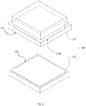
- FIG. 2 is a schematic diagram showing the first cover and the first base according to one embodiment of the invention.
- FIG. 3 a is a bottom view of the first cover in FIG. 2 ;
- FIG. 3 b is a top view of the first base in FIG. 2 ;
- FIG. 4 is a schematic diagram showing the obtained first heights on the first contact surface
- FIG. 5 is a schematic diagram showing the first contour curve
- FIG. 6 is a schematic diagram showing the distribution of the measure points on the first contact surface
- FIG. 7 a is a schematic diagram showing the first measuring path on the first contact surface according to one embodiment of the invention.
- FIG. 7 b is a schematic diagram showing the first measuring path on the first contact surface according to another embodiment of the invention.
- FIG. 7 c is a schematic diagram showing the first measuring path on the first contact surface according to yet another embodiment of the invention.
- FIG. 8 is a schematic diagram showing the obtained second heights on the second contact surface
- FIG. 9 is a schematic diagram showing the second contour curve
- FIG. 10 is a schematic diagram showing the first and the second contour curves that are in contact with each other;
- FIG. 11 is a schematic diagram showing the second cover according to one embodiment of the invention.
- FIG. 12 is a schematic diagram showing the third contour curve
- FIG. 13 is a schematic diagram showing the third and the second contour curves that are in contact with each other;
- FIG. 14 is a schematic diagram showing the second base according to one embodiment of the invention.
- FIG. 15 is a schematic diagram showing the fourth contour curve
- FIG. 16 is a schematic diagram showing the first and the fourth contour curves that are in contact with each other.
- FIG. 17 is a schematic diagram showing a system of measuring air-tightness according to one embodiment of the invention.
- the air-tightness between a cover and a base of the container is measured by using the contour curves of the two engaged contact surfaces.
- the air-tightness can be effectively determined, and one or more combinations of acceptable air-tightness among different covers and different bases can be found.
- the effect of selectively matching the cover with the base can be realized.
- FIGS. 1 a -1 c show the flow chart of a method of measuring air-tightness according to one embodiment of the invention.
- the method of measuring air-tightness of the present embodiment performs step S 11 where a first cover and a first base are provided.
- FIG. 2 is a schematic diagram showing the first cover and the first base according to one embodiment of the invention.
- FIG. 3 a is a bottom view of the first cover in FIG. 2
- FIG. 3 b is a top view of the first base in FIG. 2 .
- the first cover 110 and the first base 120 cooperate with each other in the present embodiment to form a container 100 .
- the container 100 is the one that demands a relative high air-tight property, such as the container that is used to contain the articles related to the semiconductor manufacturing process.
- the container 100 can be exemplified by a reticle pod of a reticle in one embodiment.
- the first cover 110 has a first contact surface 111 and the first base 120 has a second contact surface 121 .
- the first contact surface 111 is used for engaging with the second contact surface 121 to form an air-tight state.
- the first base 120 when the first base 120 is coupled with the first cover 110 , an accommodation space 100 a is formed between them, and an article (such as a reticle) can be contained in the accommodation space 100 a .
- the first contact surface 111 is a circular-shaped flat surface, and so is the second contact surface 121 .
- the air-tight state is formed to separate the accommodation space 100 a from the external environment of the container 100 .
- step S 12 A first contour curve relating to the first contact surface 111 is acquired.
- the step of acquiring the first contour curve (step S 12 ) of the present embodiment can be performed by the following sub-steps. First, a first start point is defined on the first contact surface 111 . Then, more than one first heights are sequentially obtained at a fixed interval by following a first measuring path on the first contact surface 111 . The first measuring path starts from the first start point. The first contour curve is acquired based on the first heights.
- FIG. 4 is a schematic diagram showing the obtained first heights on the first contact surface
- FIG. 5 is a schematic diagram showing the first contour curve.
- the first heights are obtained at different locations on the first contact surface 111 by a coordinate measuring machine (CMM).
- CCM coordinate measuring machine
- the first start point is defined on the first contact surface 111
- the first heights of more than one measure points P 1 -Pn are sequentially obtained by following the first measuring path starting from the first start point. Every two adjacent measure points P 1 -Pn are separated by the fixed interval d, and the first measure point P 1 is the first star point.
- the first contour curved C 1 can be formed based on the first heights, as shown in FIG. 5 .
- the first heights are the vertical distances measuring from a reference surface R to the measure points P 1 -Pn on the first contact surface 111 respectively.
- the reference surface R can be the top surface of the first cover 110 , so that the first heights of the measure points P 1 -Pn on the first contact surface 111 can be obtained.
- the feature of the invention is not limited hereto; other methods for obtaining the heights relating to the measure points P 1 -Pn are applicable in the present invention.
- FIG. 6 is a schematic diagram showing the distribution of the measure points on the first contact surface.
- the first heights of the measure points P 1 -Pn are sequentially obtained at the fixed interval d by following the first measure path on the first contact surface 111 along the circular-shaped first contact surface 111 .
- the fixed interval d can be adjusted in accordance with practical situations. For example, the fixed interval d can be reduced so that the number of the measure points P 1 -Pn can be increased, and the acquired first contour curve C 1 can be better conformed to the actual contour of the first contact surface 111 .
- the fixed interval d can be increased so that the number of the measure points P 1 -Pn can be reduced, and the measuring efficiency can be improved by having fewer measure points P 1 -Pn.
- the overall time consumed by the batch measurement of numerous containers 100 can be shortened.
- FIG. 7 a is a schematic diagram showing the first measuring path on the first contact surface according to one embodiment of the invention.
- the measure points P 1 -Pn in FIG. 7 a are arranged in the same way as in FIG. 6 .
- the measurement starts from the first measure point P 1 and then moves along the first measuring path 111 a (formed by the linked arrows in FIG. 7 a ) to the last measure point Pn.
- the measure points P 1 -Pn are arranged equidistantly.
- the first measure point P 1 and the last measure point Pn are different points.
- the first measuring path 111 a does not constitute a continuous loop.
- FIG. 7 b is a schematic diagram showing the first measuring path on the first contact surface according to another embodiment of the invention.
- the start point and the end point of the first measuring path 111 a ′ are the same point, so that the first measuring path 111 a ′ constitute a continuous loop.
- the measure points P 1 -Pn are not limited to the way they are arranged in FIGS. 6, 7 a and 7 b .
- the measure points P 1 -Pn can also be arranged in the shape of a multi-layer circle or a matrix.
- FIG. 7 c is a schematic diagram showing the first measuring path on the first contact surface according to yet another embodiment of the invention.
- the measure points P 1 -Pn are arranged in the shape of a dual layer circle.
- the first measuring path 111 a ′′ starts from the first measure point P 1 , ends at the last measure point Pn, and forms a spiral shape.
- the arrangement or distribution of the measure points P 1 -Pn and the shape of the first measuring path 111 a ′′ are not limited in the present invention.
- the amount, density, and arrangement of the measure points P 1 -Pn can be adjusted according to actual needs.
- the first measuring path 111 a ′ can be defined based on the type and the ability of the measuring device. Any other measuring methods that sequentially obtain multiple first heights from the first measure point P 1 to the last measure point Pn on the first contact surface 111 , to consequently acquire the first contour curve C 1 , fall within the scope of the present invention.
- step S 13 A second contour curve relating to the second contact surface 121 is acquired. Please refer to FIGS. 8 and 9 at the same time.
- FIG. 8 is a schematic diagram showing the obtained second heights on the second contact surface.
- FIG. 9 is a schematic diagram showing the second contour curve.
- the step of acquiring the second first contour curve can be performed by the following sub-steps. First, a second start point is defined on second first contact surface 121 . Then, more than one second heights are sequentially obtained at the fixed interval d by following a second measuring path on the second contact surface 121 . The second measuring path starts from the second start point.
- the second contour curve C 2 is acquired based on the second heights.
- the second heights can be obtained at different locations on the second contact surface 121 by the coordinate measuring machine in step S 13 .
- the second start point is defined on the second contact surface 121 , and then the second heights of more than one measure points are sequentially obtained by following the second measuring path starting from the second start point. Every two adjacent measure points are separated by the fixed interval d, and the first measure point is the second star point.
- the second contour curved C 2 can be formed based on the second heights.
- step S 13 the location of the second start point corresponds to the location of the first start point (the first measure point P 1 on the first contact surface 111 ).
- the fixed interval d of obtaining the second heights on the second contact surface 121 is the same as the fixed interval d on the first contact surface 111 .
- the number of the measure points on the second contact surface 121 equals to the number of measure points on the first contact surface 111 .
- step S 14 the first contour curve C 1 is brought into contact with the second contour curve C 2 .
- FIG. 10 is a schematic diagram showing the first and the second contour curves that are in contact with each other.
- a first gap shown as the shaded area in FIG. 10 , is formed between the first contour curve C 1 and the second contour curve C 2 .
- the first contour curve C 1 touches the second contour curve C 2 at a single point in the present embodiment. As shown in FIG. 10 , it is the fourth measure point from the left where the two contour curve C 1 and C 2 contact. Practically, the first contour curve C 1 may touch the second contour curve C 2 at more than one points, based on different measuring results.
- step S 15 is performed after step S 14 .
- a first gap area A 1 between the first contour curve C 1 and the second contour curve C 2 is determined.
- the space between the measure points on the first contour curves C 1 and the second contour curve C 2 is a combination of triangles and trapezoids.
- the first gap area A 1 is determined by calculating the total area of the triangles and trapezoids.
- the first gap area A 1 After the first gap area A 1 is determined, it is compared with a threshold. When the first gap area A 1 is equal to or smaller than the threshold, it means the first contour curve C 1 is relatively well matched with the second contour curve C 2 .
- the first contact surface 111 and the second contact surface 121 can achieve an acceptable air-tight property.
- the threshold can be determined by the degree of air-tightness that the container 100 needs to achieve, and the threshold is in a positive correlation with the air-tightness of the container 100 .
- the method of the present embodiment moves on to step S 16 .
- the first cover 110 and the first base 120 are paired as a first combination of acceptable air-tightness.
- a first container i.e. the container 100 in FIG. 2 ) that achieves desired or better air-tightness is formed by the first cover 110 and the first base 120 .
- first gap area A 1 is larger than the threshold, it means the combination of first cover 110 and the first base 120 cannot achieve desired air-tightness.
- another cover can be selected to match with the first base 120 to measure their air-tight property.
- FIG. 11 is a schematic diagram showing the second cover according to one embodiment of the invention.
- FIG. 12 is a schematic diagram showing the third contour curve.
- FIG. 13 is a schematic diagram showing the third and the second contour curves that are in contact with each other.
- step S 26 when the first gap area A 1 is larger than the threshold, a second cover 210 is provided.
- the second cover 210 has a third contact surface 211 for engaging with the second contact surface 121 to form an air-tight state.
- step S 27 a third contour curve C 3 relating to the third contact surface 211 is acquired.
- the third contour curve C 3 is brought into contact with the second contour curve C 2 .
- step S 29 a second gap area A 2 between the second contour curve C 2 and the third contour curve C 3 is determined.
- the contents of steps S 27 -S 29 are similar to those of the previously described steps S 12 , S 14 , and S 15 , and they will not be repeated here.
- the method of the present embodiment continues to step S 30 .
- the second cover 210 and the first base 120 are paired as a second combination of acceptable air-tightness.
- a second container that achieves desired or better air-tightness is formed by the second cover 210 and the first base 120 .
- the second gap area A 2 is larger than the threshold, it means the combination of the second cover 210 and the first base 120 cannot achieve desired air-tightness.
- Still another cover can be selected to match with the first base 120 to measure their air-tight property. Then the steps of acquiring contour curve and determining gap area are repeated.
- step S 15 when the first gap area A 1 is larger than the threshold, it means the combination of first cover 110 and the first base 120 cannot achieve desired air-tightness.
- another base can be selected to match with the first cover 110 to measure their air-tight property.
- FIG. 14 is a schematic diagram showing the second base according to one embodiment of the invention.
- FIG. 15 is a schematic diagram showing the fourth contour curve.
- FIG. 16 is a schematic diagram showing the first and the fourth contour curves that are in contact with each other.
- step S 36 when the first gap area A 1 is larger than the threshold, a second base 220 is provided.
- the second base 220 has a fourth contact surface 221 for engaging with the first contact surface 111 to form an air-tight state.
- step S 37 a fourth contour curve C 4 relating to the fourth contact surface 221 is acquired.
- the fourth contour curve C 4 is brought into contact with the first contour curve C 1 .
- step S 39 a third gap area A 3 between the fourth contour curve C 4 and the first contour curve C 1 is determined.
- the contents of steps S 37 -S 39 are similar to those of the previously described steps S 12 , S 14 , and S 15 , and they will not be repeated here.
- the method of the present embodiment continues to step S 40 .
- the first cover 110 and the second base 220 are paired as a third combination of acceptable air-tightness.
- a third container that achieves desired or better air-tightness is formed by the first cover 110 and the second base 220 .
- the third gap area A 3 is larger than the threshold, it means the combination of the first cover 110 and the second base 220 cannot achieve desired air-tightness.
- Still another base can be selected to match with the first cover 110 to measure their air-tight property. Then the steps of acquiring contour curve and determining gap area are repeated.
- the first gap area between the two curves can be used to determine whether the air-tightness is acceptable or not.
- the first cover and the first base are paired as a first combination of acceptable air-tightness.
- the container formed by the first cover and the first base meets the desired or better air-tight property.
- the measuring method for the air-tight property of the cover and the base can be more efficient and can be simplified by using the contour curves.
- a surface finish with a roughness average (RA) of up to 0.50 micro inches is acceptable.
- an air-tightness property index of the two engaged contact surfaces can be acquired, and the threshold of the gap area can be determined accordingly.
- the air-tightness property index is X
- the threshold derived from X is A. That is to say, when the gap area equals to A, the cover and base have an air-tightness property index same as the two engaged contact surfaces each having 0.50 micro inches RA.
- the combination of the cover and the base can still achieve desired air-tightness.
- the first contact surface of the cover has an RA far greater than 0.50 micro inches (say 5 micro inches, or higher) and the second contact surface of the base also has an RA far greater than 0.50 micro inches (say 5 micro inches, or higher)
- the combination of the cover and base can achieve the expected air-tightness property index X.
- the cover and the base each having an RA larger than 0.50 micro inches, can still be selected and be used to form the container. They are not limited by the restriction of 0.50 micro inches RA as described in the disclosure of related art. As a result, the requirement for flatness of the first contact surface and the second contact surface can be lowered, and thus the processing cost can be lowered as well. Moreover, the variation of air-tightness across different cover-and-base combinations can be reduced through the selectively matching process, and the consistency of air-tight property across different containers can be maintained.
- FIG. 17 is a schematic diagram showing a system of measuring air-tightness according to one embodiment of the invention.
- the system 300 of measuring air-tightness is used for measuring a cover and a base.
- the cover has a first contact surface and the base has a second contact surface.
- the first contact surface is used for engaging with the second contact surface to form an air-tight state.
- the system 300 includes a measuring unit 310 and a processing unit 330 .
- the measuring unit 310 is used for acquiring a first contour curve relating to the first contact surface and a second contour curve relating to the second contact surface.
- the processing unit 330 is used for determining a gap area between the first contour curve and the second contour curve as the two contour curves are in contact with each other.
- the processing unit 330 is used for pairing the cover and the base as a combination of acceptable air-tightness when the gap area is equal to or smaller than a threshold, so as to form a container.
- the measuring unit 310 sequentially obtains more than one first heights at a fixed interval from a first start point on the first contact surface.
- the measuring unit 310 also sequentially obtains more than one second heights at the same fixed interval from a second start point on the second contact surface.
- the system 300 of the present embodiment can be exemplified by measuring previously mentioned first cover 110 and first base 120 as shown in FIGS. 2-10 .
- the measuring unit 310 can be used to measure the second cover 210 to acquire the third contour curve C 3 relating to the second cover 210 .
- the processing unit 330 determines the second gap area A 2 between the third contour curve C 3 and the second contour curve C 2 .
- the measuring unit 310 can be used to measure the second base 220 to acquire the fourth contour curve C 4 relating to the second base 220 .
- the processing unit 330 determines the third gap area A 3 between the first contour curve C 1 and the fourth contour curve C 4 .
- the technical details here are similar to the above mentioned embodiment of the method of measuring air-tightness, and will not be repeated herein.
- the measuring unit 310 can be a coordinate measuring machine. Yet the present invention is not limited thereto, other measuring technics or devices that can obtain the heights at different locations on the first contact surface and on the second contact surface can be used in the present invention.
- the processing unit 330 can be a local computer, a remotely connected server, or other similar devices. Their contents or details are not limited in the present invention.
- a container includes a cover and a base for cooperating with each other to contain a reticle.
- the cover has a first contact surface and the base has a second contact surface for engaging with the first contact surface to form an air-tight state.
- the cover and the base of the present embodiment container are paired through a method of measuring air-tightness (e.g. the method shown in FIG. 1 a -1 c ) or a system of measuring air-tightness (e.g. the system 300 shown in FIG. 17 ) in the above-mentioned embodiments.
- Their contents and details are similar to those of the container 100 in the embodiment accompanying FIG. 2 , and will not be repeated herein.
- the method and the system of measuring air-tightness and the container measured thereby of the embodiments of the present invention determine the air-tightness of the two engaged contact surfaces by acquiring the contour curves of the surfaces. After the first contour curve relating to the first contact surface of the cover and the second contour curve relating to the second contact surface of the base are acquired, the two contour curves are brought into contact with each other. The gap area between the two contour curves is then determined. When the gap area is equal to or smaller than the threshold, the cover and the base are paired as a combination of acceptable air-tightness, so as to form the container. By measuring the contour curves of the engaged surfaces and determining the gap area, the air-tightness measuring efficiency can be improved.
Landscapes
- Physics & Mathematics (AREA)
- General Physics & Mathematics (AREA)
- Engineering & Computer Science (AREA)
- Library & Information Science (AREA)
- Mechanical Engineering (AREA)
- Examining Or Testing Airtightness (AREA)
- Closures For Containers (AREA)
- Length Measuring Devices With Unspecified Measuring Means (AREA)
Abstract
Description
Claims (10)
Priority Applications (1)
| Application Number | Priority Date | Filing Date | Title |
|---|---|---|---|
| US16/039,689 US11031267B2 (en) | 2017-08-14 | 2018-07-19 | Method and system of measuring air-tightness and container measured thereby |
Applications Claiming Priority (2)
| Application Number | Priority Date | Filing Date | Title |
|---|---|---|---|
| US201762544996P | 2017-08-14 | 2017-08-14 | |
| US16/039,689 US11031267B2 (en) | 2017-08-14 | 2018-07-19 | Method and system of measuring air-tightness and container measured thereby |
Publications (2)
| Publication Number | Publication Date |
|---|---|
| US20190051549A1 US20190051549A1 (en) | 2019-02-14 |
| US11031267B2 true US11031267B2 (en) | 2021-06-08 |
Family
ID=65275597
Family Applications (1)
| Application Number | Title | Priority Date | Filing Date |
|---|---|---|---|
| US16/039,689 Active 2038-12-12 US11031267B2 (en) | 2017-08-14 | 2018-07-19 | Method and system of measuring air-tightness and container measured thereby |
Country Status (3)
| Country | Link |
|---|---|
| US (1) | US11031267B2 (en) |
| KR (1) | KR102134639B1 (en) |
| TW (1) | TWI696886B (en) |
Families Citing this family (1)
| Publication number | Priority date | Publication date | Assignee | Title |
|---|---|---|---|---|
| TWI705522B (en) * | 2019-07-30 | 2020-09-21 | 家登精密工業股份有限公司 | Apparatus for containing a substrate and method of manufacturing the apparatus |
Citations (22)
| Publication number | Priority date | Publication date | Assignee | Title |
|---|---|---|---|---|
| US5489987A (en) * | 1994-04-07 | 1996-02-06 | Owens-Brockway Glass Container Inc. | Container sealing surface inspection |
| JPH11183134A (en) | 1996-12-02 | 1999-07-09 | Espace Ind Controle Sa | Method for measuring interval and displacement amount between facing parts |
| US20040085311A1 (en) * | 1998-07-23 | 2004-05-06 | Curventa Softworks, Llc. | Computational geometry using control geometry having at least two dimensions |
| US20060087639A1 (en) * | 2002-02-22 | 2006-04-27 | Asml Holding N.V. | System and method for using a two part cover for and a box for protecting a reticle |
| US20060127205A1 (en) * | 2004-12-15 | 2006-06-15 | Gudeng Precision Industrial Co., Ltd. | [airtight semiconductor transferring container] |
| US20070200476A1 (en) * | 2006-02-28 | 2007-08-30 | Yuuichi Kijima | Display device |
| US20070296963A1 (en) * | 2004-05-20 | 2007-12-27 | Sepha Limited | Methods and Apparatus for Inspecting the Sealing and Integrity of Blister Packages |
| US7400383B2 (en) * | 2005-04-04 | 2008-07-15 | Entegris, Inc. | Environmental control in a reticle SMIF pod |
| US20090027397A1 (en) * | 2007-07-26 | 2009-01-29 | Tufts University | Method for fitting a parametric representation to a set of objects generated by a digital sketching device |
| US20090199963A1 (en) * | 2008-02-07 | 2009-08-13 | Canon Kabushiki Kaisha | Airtight container manufacturing method, and image displaying apparatus manufacturing method using airtight container manufacturing method |
| US7607543B2 (en) * | 2005-02-27 | 2009-10-27 | Entegris, Inc. | Reticle pod with isolation system |
| US20100201519A1 (en) * | 2006-10-06 | 2010-08-12 | University Of Maine System Board Of Trustees | Breach detection system for containers |
| KR100994741B1 (en) | 2010-05-04 | 2010-11-16 | 주식회사 덕인 | The method of measuring unknown curve with measurement step optimization based on the surface curvature using 3 dimensional coordinate measuring machine |
| US20100294397A1 (en) * | 2006-06-19 | 2010-11-25 | Entegris, Inc. | System for purging reticle storage |
| US20120073727A1 (en) * | 2010-09-27 | 2012-03-29 | Canon Kabushiki Kaisha | Manufacturing method of hermetically sealed container for holding therein atmosphere of reduced pressure |
| US8231005B2 (en) * | 2005-09-27 | 2012-07-31 | Entegris, Inc. | Reticle pod |
| US8403143B2 (en) * | 2009-09-25 | 2013-03-26 | Gudeng Precision Industrial Co, Ltd | Reticle storing container |
| US20130278927A1 (en) * | 2010-11-01 | 2013-10-24 | Make-All Corporation | Raised Vial Stopper Detection System |
| US9022216B2 (en) * | 2011-11-17 | 2015-05-05 | Gudeng Precision Industrial Co., Ltd. | Reticle pod with drain structure |
| US20150241360A1 (en) * | 2012-11-13 | 2015-08-27 | Focalspec Oy | Apparatus and method for inspecting seals of items |
| US20180210349A1 (en) * | 2017-01-25 | 2018-07-26 | Gudeng Precision Industrial Co, Ltd | EUV Reticle Pod |
| US10677582B2 (en) * | 2018-07-30 | 2020-06-09 | Grifols Worldwide Operations Limited | Method and device for detecting defects in the closure of encapsulated vials |
Family Cites Families (3)
| Publication number | Priority date | Publication date | Assignee | Title |
|---|---|---|---|---|
| TWM276318U (en) * | 2005-03-29 | 2005-09-21 | Fortrend Taiwan Scient Corp | Wafer cassette inspection machine |
| JP4624458B2 (en) * | 2008-11-11 | 2011-02-02 | Tdk株式会社 | Sealed container and lid opening / closing system of the sealed container |
| CN205826241U (en) * | 2016-07-06 | 2016-12-21 | 青海时代新能源科技有限公司 | Air-tightness detection device |
-
2018
- 2018-07-12 KR KR1020180080971A patent/KR102134639B1/en active Active
- 2018-07-19 US US16/039,689 patent/US11031267B2/en active Active
- 2018-07-23 TW TW107125337A patent/TWI696886B/en active
Patent Citations (23)
| Publication number | Priority date | Publication date | Assignee | Title |
|---|---|---|---|---|
| US5489987A (en) * | 1994-04-07 | 1996-02-06 | Owens-Brockway Glass Container Inc. | Container sealing surface inspection |
| JPH11183134A (en) | 1996-12-02 | 1999-07-09 | Espace Ind Controle Sa | Method for measuring interval and displacement amount between facing parts |
| US20040085311A1 (en) * | 1998-07-23 | 2004-05-06 | Curventa Softworks, Llc. | Computational geometry using control geometry having at least two dimensions |
| US20060087639A1 (en) * | 2002-02-22 | 2006-04-27 | Asml Holding N.V. | System and method for using a two part cover for and a box for protecting a reticle |
| US20070296963A1 (en) * | 2004-05-20 | 2007-12-27 | Sepha Limited | Methods and Apparatus for Inspecting the Sealing and Integrity of Blister Packages |
| US20060127205A1 (en) * | 2004-12-15 | 2006-06-15 | Gudeng Precision Industrial Co., Ltd. | [airtight semiconductor transferring container] |
| US7607543B2 (en) * | 2005-02-27 | 2009-10-27 | Entegris, Inc. | Reticle pod with isolation system |
| US7400383B2 (en) * | 2005-04-04 | 2008-07-15 | Entegris, Inc. | Environmental control in a reticle SMIF pod |
| US8231005B2 (en) * | 2005-09-27 | 2012-07-31 | Entegris, Inc. | Reticle pod |
| TWI391304B (en) | 2005-09-27 | 2013-04-01 | 安堤格里斯公司 | Mask box |
| US20070200476A1 (en) * | 2006-02-28 | 2007-08-30 | Yuuichi Kijima | Display device |
| US20100294397A1 (en) * | 2006-06-19 | 2010-11-25 | Entegris, Inc. | System for purging reticle storage |
| US20100201519A1 (en) * | 2006-10-06 | 2010-08-12 | University Of Maine System Board Of Trustees | Breach detection system for containers |
| US20090027397A1 (en) * | 2007-07-26 | 2009-01-29 | Tufts University | Method for fitting a parametric representation to a set of objects generated by a digital sketching device |
| US20090199963A1 (en) * | 2008-02-07 | 2009-08-13 | Canon Kabushiki Kaisha | Airtight container manufacturing method, and image displaying apparatus manufacturing method using airtight container manufacturing method |
| US8403143B2 (en) * | 2009-09-25 | 2013-03-26 | Gudeng Precision Industrial Co, Ltd | Reticle storing container |
| KR100994741B1 (en) | 2010-05-04 | 2010-11-16 | 주식회사 덕인 | The method of measuring unknown curve with measurement step optimization based on the surface curvature using 3 dimensional coordinate measuring machine |
| US20120073727A1 (en) * | 2010-09-27 | 2012-03-29 | Canon Kabushiki Kaisha | Manufacturing method of hermetically sealed container for holding therein atmosphere of reduced pressure |
| US20130278927A1 (en) * | 2010-11-01 | 2013-10-24 | Make-All Corporation | Raised Vial Stopper Detection System |
| US9022216B2 (en) * | 2011-11-17 | 2015-05-05 | Gudeng Precision Industrial Co., Ltd. | Reticle pod with drain structure |
| US20150241360A1 (en) * | 2012-11-13 | 2015-08-27 | Focalspec Oy | Apparatus and method for inspecting seals of items |
| US20180210349A1 (en) * | 2017-01-25 | 2018-07-26 | Gudeng Precision Industrial Co, Ltd | EUV Reticle Pod |
| US10677582B2 (en) * | 2018-07-30 | 2020-06-09 | Grifols Worldwide Operations Limited | Method and device for detecting defects in the closure of encapsulated vials |
Also Published As
| Publication number | Publication date |
|---|---|
| TW201910914A (en) | 2019-03-16 |
| KR20190018388A (en) | 2019-02-22 |
| TWI696886B (en) | 2020-06-21 |
| US20190051549A1 (en) | 2019-02-14 |
| KR102134639B1 (en) | 2020-07-17 |
Similar Documents
| Publication | Publication Date | Title |
|---|---|---|
| KR102046192B1 (en) | Overlay and semiconductor process control using a novel wafer geometry metric | |
| US7957118B2 (en) | Multi-zone electrostatic chuck and chucking method | |
| US10572991B2 (en) | System and method for aligning semiconductor device reference images and test images | |
| US9588441B2 (en) | Method and device for using substrate geometry to determine optimum substrate analysis sampling | |
| US20190219929A1 (en) | Methods & apparatus for obtaining diagnostic information relating to a lithographic manufacturing process | |
| US8225683B2 (en) | Wafer bow metrology arrangements and methods thereof | |
| US10024654B2 (en) | Method and system for determining in-plane distortions in a substrate | |
| JP5792069B2 (en) | Method and system for centering a wafer on a chuck | |
| CN112880597A (en) | Wafer Flatness Measurement Method | |
| EP3918421B1 (en) | Tool architecture for wafer geometry measurement in semiconductor industry | |
| US12072176B2 (en) | Measuring apparatus and method of wafer geometry | |
| US10504761B2 (en) | Method system for generating 3D composite images of objects and determining object properties based thereon | |
| JP2016053558A (en) | Inspection method | |
| CN109923654B (en) | Wafer noise reduction via image subtraction across layers | |
| JP2023516872A (en) | Film thickness estimation from substrate image processing based on machine learning | |
| TW201716886A (en) | Substrate processing device, substrate processing method, and memory medium | |
| CN112908909A (en) | Wafer memory device, associated methods and apparatus | |
| CN106705880A (en) | Large diameter mirror surface profile in-place detecting method and device | |
| US11031267B2 (en) | Method and system of measuring air-tightness and container measured thereby | |
| CN105789079B (en) | A kind of location aided rebroadcast chip die mapping method | |
| US20200135519A1 (en) | Shape-Distortion Standards for Calibrating Measurement Tools for Nominally Flat Objects | |
| KR20160098640A (en) | Device handler, and vision inspection method | |
| CN107665831A (en) | System and method for the measurement of semiconductor devices manufacture instruments and implement | |
| HK40012888B (en) | Method and system for generating 3d composite images of packaged semiconductor devices and determining device properties based thereon | |
| HK40012888A (en) | Method and system for generating 3d composite images of packaged semiconductor devices and determining device properties based thereon |
Legal Events
| Date | Code | Title | Description |
|---|---|---|---|
| AS | Assignment |
Owner name: GUDENG PRECISION INDUSTRIAL CO., LTD, TAIWAN Free format text: ASSIGNMENT OF ASSIGNORS INTEREST;ASSIGNORS:CHUANG, CHIA-HO;LIN, SHU-HUNG;REEL/FRAME:046591/0915 Effective date: 20180621 |
|
| FEPP | Fee payment procedure |
Free format text: ENTITY STATUS SET TO UNDISCOUNTED (ORIGINAL EVENT CODE: BIG.); ENTITY STATUS OF PATENT OWNER: SMALL ENTITY |
|
| FEPP | Fee payment procedure |
Free format text: ENTITY STATUS SET TO SMALL (ORIGINAL EVENT CODE: SMAL); ENTITY STATUS OF PATENT OWNER: SMALL ENTITY |
|
| STPP | Information on status: patent application and granting procedure in general |
Free format text: DOCKETED NEW CASE - READY FOR EXAMINATION |
|
| STPP | Information on status: patent application and granting procedure in general |
Free format text: NON FINAL ACTION MAILED |
|
| STPP | Information on status: patent application and granting procedure in general |
Free format text: RESPONSE TO NON-FINAL OFFICE ACTION ENTERED AND FORWARDED TO EXAMINER |
|
| STPP | Information on status: patent application and granting procedure in general |
Free format text: FINAL REJECTION MAILED |
|
| STPP | Information on status: patent application and granting procedure in general |
Free format text: DOCKETED NEW CASE - READY FOR EXAMINATION |
|
| STPP | Information on status: patent application and granting procedure in general |
Free format text: NON FINAL ACTION MAILED |
|
| STPP | Information on status: patent application and granting procedure in general |
Free format text: RESPONSE TO NON-FINAL OFFICE ACTION ENTERED AND FORWARDED TO EXAMINER |
|
| STPP | Information on status: patent application and granting procedure in general |
Free format text: NOTICE OF ALLOWANCE MAILED -- APPLICATION RECEIVED IN OFFICE OF PUBLICATIONS |
|
| STPP | Information on status: patent application and granting procedure in general |
Free format text: PUBLICATIONS -- ISSUE FEE PAYMENT RECEIVED |
|
| STPP | Information on status: patent application and granting procedure in general |
Free format text: PUBLICATIONS -- ISSUE FEE PAYMENT VERIFIED |
|
| STCF | Information on status: patent grant |
Free format text: PATENTED CASE |
|
| MAFP | Maintenance fee payment |
Free format text: PAYMENT OF MAINTENANCE FEE, 4TH YR, SMALL ENTITY (ORIGINAL EVENT CODE: M2551); ENTITY STATUS OF PATENT OWNER: SMALL ENTITY Year of fee payment: 4 |
|
| FEPP | Fee payment procedure |
Free format text: ENTITY STATUS SET TO UNDISCOUNTED (ORIGINAL EVENT CODE: BIG.); ENTITY STATUS OF PATENT OWNER: LARGE ENTITY |
|
| MAFP | Maintenance fee payment |
Free format text: PAYMENT OF MAINTENANCE FEE UNDER 1.28(C) (ORIGINAL EVENT CODE: M1559); ENTITY STATUS OF PATENT OWNER: LARGE ENTITY |