US11013355B2 - Modular tree with electrical connector - Google Patents
Modular tree with electrical connector Download PDFInfo
- Publication number
- US11013355B2 US11013355B2 US16/725,974 US201916725974A US11013355B2 US 11013355 B2 US11013355 B2 US 11013355B2 US 201916725974 A US201916725974 A US 201916725974A US 11013355 B2 US11013355 B2 US 11013355B2
- Authority
- US
- United States
- Prior art keywords
- electrical connector
- electrical
- tree
- trunk body
- light string
- Prior art date
- Legal status (The legal status is an assumption and is not a legal conclusion. Google has not performed a legal analysis and makes no representation as to the accuracy of the status listed.)
- Active
Links
- 230000008878 coupling Effects 0.000 claims description 12
- 238000010168 coupling process Methods 0.000 claims description 12
- 238000005859 coupling reaction Methods 0.000 claims description 12
- WABPQHHGFIMREM-UHFFFAOYSA-N lead(0) Chemical compound [Pb] WABPQHHGFIMREM-UHFFFAOYSA-N 0.000 description 20
- 230000000712 assembly Effects 0.000 description 18
- 238000000429 assembly Methods 0.000 description 18
- 239000004020 conductor Substances 0.000 description 10
- 230000008901 benefit Effects 0.000 description 6
- 238000010276 construction Methods 0.000 description 4
- 238000003780 insertion Methods 0.000 description 4
- 230000037431 insertion Effects 0.000 description 4
- 238000010348 incorporation Methods 0.000 description 3
- 238000009429 electrical wiring Methods 0.000 description 2
- 230000013011 mating Effects 0.000 description 2
- 239000002184 metal Substances 0.000 description 2
- 238000012986 modification Methods 0.000 description 2
- 230000004048 modification Effects 0.000 description 2
- 230000007935 neutral effect Effects 0.000 description 2
- 238000003860 storage Methods 0.000 description 2
- 241000191291 Abies alba Species 0.000 description 1
- 235000008331 Pinus X rigitaeda Nutrition 0.000 description 1
- 235000011613 Pinus brutia Nutrition 0.000 description 1
- 241000018646 Pinus brutia Species 0.000 description 1
- 239000000853 adhesive Substances 0.000 description 1
- 230000001070 adhesive effect Effects 0.000 description 1
- 238000004891 communication Methods 0.000 description 1
- 238000010586 diagram Methods 0.000 description 1
- 230000000694 effects Effects 0.000 description 1
- 238000005562 fading Methods 0.000 description 1
- 239000012212 insulator Substances 0.000 description 1
- 238000005304 joining Methods 0.000 description 1
- 238000004519 manufacturing process Methods 0.000 description 1
- 239000000463 material Substances 0.000 description 1
- 238000000034 method Methods 0.000 description 1
- 239000012811 non-conductive material Substances 0.000 description 1
- 230000008520 organization Effects 0.000 description 1
- 229910000679 solder Inorganic materials 0.000 description 1
- 230000000007 visual effect Effects 0.000 description 1
Images


Classifications
-
- A—HUMAN NECESSITIES
- A47—FURNITURE; DOMESTIC ARTICLES OR APPLIANCES; COFFEE MILLS; SPICE MILLS; SUCTION CLEANERS IN GENERAL
- A47G—HOUSEHOLD OR TABLE EQUIPMENT
- A47G33/00—Religious or ritual equipment in dwelling or for general use
- A47G33/04—Christmas trees
- A47G33/06—Artificial Christmas trees
-
- A—HUMAN NECESSITIES
- A41—WEARING APPAREL
- A41G—ARTIFICIAL FLOWERS; WIGS; MASKS; FEATHERS
- A41G1/00—Artificial flowers, fruit, leaves, or trees; Garlands
- A41G1/001—Artificial flowers, fruit, leaves, or trees; Garlands characterised by their special functions
- A41G1/005—Artificial flowers, fruit, leaves, or trees; Garlands characterised by their special functions luminous or luminescent
-
- A—HUMAN NECESSITIES
- A41—WEARING APPAREL
- A41G—ARTIFICIAL FLOWERS; WIGS; MASKS; FEATHERS
- A41G1/00—Artificial flowers, fruit, leaves, or trees; Garlands
- A41G1/007—Artificial trees
-
- A—HUMAN NECESSITIES
- A47—FURNITURE; DOMESTIC ARTICLES OR APPLIANCES; COFFEE MILLS; SPICE MILLS; SUCTION CLEANERS IN GENERAL
- A47G—HOUSEHOLD OR TABLE EQUIPMENT
- A47G33/00—Religious or ritual equipment in dwelling or for general use
- A47G33/04—Christmas trees
- A47G33/08—Christmas tree decorations
-
- F—MECHANICAL ENGINEERING; LIGHTING; HEATING; WEAPONS; BLASTING
- F21—LIGHTING
- F21S—NON-PORTABLE LIGHTING DEVICES; SYSTEMS THEREOF; VEHICLE LIGHTING DEVICES SPECIALLY ADAPTED FOR VEHICLE EXTERIORS
- F21S2/00—Systems of lighting devices, not provided for in main groups F21S4/00 - F21S10/00 or F21S19/00, e.g. of modular construction
- F21S2/005—Systems of lighting devices, not provided for in main groups F21S4/00 - F21S10/00 or F21S19/00, e.g. of modular construction of modular construction
-
- F—MECHANICAL ENGINEERING; LIGHTING; HEATING; WEAPONS; BLASTING
- F21—LIGHTING
- F21S—NON-PORTABLE LIGHTING DEVICES; SYSTEMS THEREOF; VEHICLE LIGHTING DEVICES SPECIALLY ADAPTED FOR VEHICLE EXTERIORS
- F21S4/00—Lighting devices or systems using a string or strip of light sources
- F21S4/10—Lighting devices or systems using a string or strip of light sources with light sources attached to loose electric cables, e.g. Christmas tree lights
-
- F—MECHANICAL ENGINEERING; LIGHTING; HEATING; WEAPONS; BLASTING
- F21—LIGHTING
- F21V—FUNCTIONAL FEATURES OR DETAILS OF LIGHTING DEVICES OR SYSTEMS THEREOF; STRUCTURAL COMBINATIONS OF LIGHTING DEVICES WITH OTHER ARTICLES, NOT OTHERWISE PROVIDED FOR
- F21V23/00—Arrangement of electric circuit elements in or on lighting devices
- F21V23/001—Arrangement of electric circuit elements in or on lighting devices the elements being electrical wires or cables
-
- F—MECHANICAL ENGINEERING; LIGHTING; HEATING; WEAPONS; BLASTING
- F21—LIGHTING
- F21V—FUNCTIONAL FEATURES OR DETAILS OF LIGHTING DEVICES OR SYSTEMS THEREOF; STRUCTURAL COMBINATIONS OF LIGHTING DEVICES WITH OTHER ARTICLES, NOT OTHERWISE PROVIDED FOR
- F21V23/00—Arrangement of electric circuit elements in or on lighting devices
- F21V23/02—Arrangement of electric circuit elements in or on lighting devices the elements being transformers, impedances or power supply units, e.g. a transformer with a rectifier
-
- F—MECHANICAL ENGINEERING; LIGHTING; HEATING; WEAPONS; BLASTING
- F21—LIGHTING
- F21V—FUNCTIONAL FEATURES OR DETAILS OF LIGHTING DEVICES OR SYSTEMS THEREOF; STRUCTURAL COMBINATIONS OF LIGHTING DEVICES WITH OTHER ARTICLES, NOT OTHERWISE PROVIDED FOR
- F21V23/00—Arrangement of electric circuit elements in or on lighting devices
- F21V23/06—Arrangement of electric circuit elements in or on lighting devices the elements being coupling devices, e.g. connectors
-
- F—MECHANICAL ENGINEERING; LIGHTING; HEATING; WEAPONS; BLASTING
- F21—LIGHTING
- F21V—FUNCTIONAL FEATURES OR DETAILS OF LIGHTING DEVICES OR SYSTEMS THEREOF; STRUCTURAL COMBINATIONS OF LIGHTING DEVICES WITH OTHER ARTICLES, NOT OTHERWISE PROVIDED FOR
- F21V33/00—Structural combinations of lighting devices with other articles, not otherwise provided for
- F21V33/0004—Personal or domestic articles
- F21V33/0024—Household or table equipment
- F21V33/0028—Decorative household equipment, e.g. plant holders or food dummies
-
- H—ELECTRICITY
- H01—ELECTRIC ELEMENTS
- H01R—ELECTRICALLY-CONDUCTIVE CONNECTIONS; STRUCTURAL ASSOCIATIONS OF A PLURALITY OF MUTUALLY-INSULATED ELECTRICAL CONNECTING ELEMENTS; COUPLING DEVICES; CURRENT COLLECTORS
- H01R31/00—Coupling parts supported only by co-operation with counterpart
-
- A—HUMAN NECESSITIES
- A47—FURNITURE; DOMESTIC ARTICLES OR APPLIANCES; COFFEE MILLS; SPICE MILLS; SUCTION CLEANERS IN GENERAL
- A47G—HOUSEHOLD OR TABLE EQUIPMENT
- A47G33/00—Religious or ritual equipment in dwelling or for general use
- A47G33/04—Christmas trees
- A47G33/08—Christmas tree decorations
- A47G2033/0827—Christmas tree decorations illuminated
-
- F—MECHANICAL ENGINEERING; LIGHTING; HEATING; WEAPONS; BLASTING
- F21—LIGHTING
- F21V—FUNCTIONAL FEATURES OR DETAILS OF LIGHTING DEVICES OR SYSTEMS THEREOF; STRUCTURAL COMBINATIONS OF LIGHTING DEVICES WITH OTHER ARTICLES, NOT OTHERWISE PROVIDED FOR
- F21V23/00—Arrangement of electric circuit elements in or on lighting devices
- F21V23/04—Arrangement of electric circuit elements in or on lighting devices the elements being switches
- F21V23/0407—Arrangement of electric circuit elements in or on lighting devices the elements being switches for flashing
-
- F—MECHANICAL ENGINEERING; LIGHTING; HEATING; WEAPONS; BLASTING
- F21—LIGHTING
- F21W—INDEXING SCHEME ASSOCIATED WITH SUBCLASSES F21K, F21L, F21S and F21V, RELATING TO USES OR APPLICATIONS OF LIGHTING DEVICES OR SYSTEMS
- F21W2121/00—Use or application of lighting devices or systems for decorative purposes, not provided for in codes F21W2102/00 – F21W2107/00
- F21W2121/04—Use or application of lighting devices or systems for decorative purposes, not provided for in codes F21W2102/00 – F21W2107/00 for Christmas trees
-
- H—ELECTRICITY
- H01—ELECTRIC ELEMENTS
- H01R—ELECTRICALLY-CONDUCTIVE CONNECTIONS; STRUCTURAL ASSOCIATIONS OF A PLURALITY OF MUTUALLY-INSULATED ELECTRICAL CONNECTING ELEMENTS; COUPLING DEVICES; CURRENT COLLECTORS
- H01R2103/00—Two poles
Definitions
- the present invention is generally directed to artificial trees. More specifically, the present invention is directed to artificial trees having separable, modular tree portions electrically connectable between trunk portions.
- artificial trees constructed of metal and plastic for natural evergreen trees when decorating homes, offices, and other spaces, especially during the holidays.
- Such artificial trees generally include multiple tree sections joined at the trunk and held erect by a floor-based tree stand.
- consumers wrap strings of lights about the artificial tree to enhance the decorative quality of the tree display. As more and more decorative light strings are draped around the tree, it becomes more and more difficult to provide power to the various light strings distributed throughout the tree.
- pre-lit trees include an artificial tree with multiple standard light strings distributed about the exterior of the tree. Wires of the light string are clipped to branch structures, while plug ends dangle throughout the branches.
- multi-purpose decorative light strings are used in pre-lit trees, often limited to 50 or 100 bulb assemblies, with a bladed power plug for insertion into the back outlet of another light string, or insertion into an alternating current (AC) power source.
- AC alternating current
- pre-lit trees As the popularity of such pre-lit trees has grown, so to have the bulk and complexity of pre-lit trees. Along with an increase in the number and density of branches of a typical pre-lit tree comes an increase in the number of lights and light strings on the pre-lit tree. This increased number of branches and lights can significantly increase the weight of the pre-lit tree making it difficult to lift and align individual trunk sections when assembling the tree. Further, the increased number of lights per tree, often as high as 1,000 or 1,500 lights, drastically increases the complexity of interconnecting and powering the numerous light strings.
- Light strings may be connected to one another within a given tree section, or sometimes between sections, by connecting the strings end to end. Consumers need to be careful to follow the manufacturer's guidelines and not plug too many light strings together end-to-end and surpass the current-carrying capacity of the light string wiring. Due to such limitations, power plugs of the light strings may include receptacles for receiving other power plugs such that the power plugs may be “stacked” together, plugging one into the other. Short extension cords may be strung along the outside of the trunk to carry power to the various interconnected light strings. The result is a complex web of lighting that often requires a consumer to not only interconnect the plugs and receptacles of individual light strings together, but to stack and plug multiple light strings and cords into multiple power outlets.
- U.S. Pat. No. 1,656,148 to Harris filed Apr. 5, 1926 and entitled “Artificial Christmas Tree” teaches a simple artificial tree with one embodiment having multiple tree sections that join together.
- the tree includes single bulbs at each end of a branch, with bulb wiring extending from inside a trunk through hollow branches.
- a bayonet fitting is used to adjoin the sections, a top section having a projecting pin, and a bottom section having an L-shaped bayonet slot.
- the two sections are coupled by aligning the projection pin with the bayonet slot and rotating to interlock the sections, thereby bringing a pair of spring contacts into alignment with a pair of terminals to make an electrical connection.
- FIG. 1 Another known artificial tree as described in U.S. Pat. No. 3,970,834 to Smith, filed Dec. 16, 1974 and entitled “Artificial Tree”, describes a pre-lit tree made in sections which may be folded for easy storage.
- the individual tree sections include a threaded male end and a threaded female socket end.
- the male end of a tree section is screwed into the female end of another section.
- Wiring for the lights passes from the trunk through holes in branches and connects with individual lights at an interior of the branch. When the tree is screwed together, an electrical connection is made.
- the claimed invention comprises a lighted artificial tree that includes: a first tree portion aligned along a central vertical axis, the first tree portion including: a first trunk body having a first end, a second end, a first electrical connector positioned in the second end of the first trunk body and including a first electrical terminal positioned in line with the central vertical axis, and a second electrical terminal.
- the tree also includes a second tree portion aligned with the central vertical axis, the second tree portion including: a second trunk body including a first end and a second end, the first end configured to couple with the second end of the first trunk body of the first tree portion; a second electrical connector positioned in the first end of the second trunk body and including a first electrical terminal and a second electrical terminal, the second electrical terminal defining a ring shape that encircles the first electrical terminal, the second electrical connector configured to couple with the first electrical connector of the first trunk body; and a light string electrically connected to the first and the second electrical terminals of the second electrical connector.
- the first electrical connector is coupled to the second electrical connector, such that the first electrical terminal of the first electrical connector is electrically connected to the first electrical terminal of the second electrical connector, and the second electrical terminal of the first electrical connector is electrically connected to the second electrical terminal of the second electrical connector.
- the claimed invention comprises a lighted artificial tree, comprising a first tree portion and a second tree portion.
- the first tree portion is aligned along a central vertical axis and includes: a first trunk body having a first end, a second end, a first electrical connector positioned in the second end of the first trunk body and including a first electrical terminal, a second electrical terminal, and a third electrical terminal.
- the second tree portion is also aligned with the central vertical axis and includes: a second trunk body including a first end and a second end, the first end configured to couple with the second end of the first trunk body of the first tree portion; a second electrical connector positioned in the first end of the second trunk body and including a first electrical terminal, a second electrical terminal, and a third electrical terminal; a light string electrically connected to the second electrical connector.
- the first electrical connector is coupled to the second electrical connector, such that the first electrical terminal of the first electrical connector is electrically connected to the first electrical terminal of the second electrical connector, the second terminal of the first electrical connector is electrically connected to the second electrical terminal of the second electrical connector, and the third electrical terminal of the first electrical connector is electrically connected to the third electrical terminal of the second electrical connector.
- the claimed invention comprises a lighted artificial tree that includes: a first trunk body having a first trunk wall and a first electrical wiring harness assembly comprising: a first electrical connector positioned substantially within the first trunk body and including a first electrical terminal and a second electrical terminal; a first wiring harness positioned at least in part within the first trunk body and comprising a first wire and a second wire, the first wire electrically connected to the first electrical terminal and the second wire electrically connected to the second electrical terminal.
- the tree also includes a first light string having a first wire, a plurality of intermediate wires, a plurality of light element assemblies, and a last wire, a first end of the first wire being electrically connected to the first wire of the first wiring harness, a second end of the first wire being electrically connected to a first light element assembly of the plurality of light element assemblies, each of the intermediate wires being electrically connected at a first end to one of the plurality of light element assemblies and electrically connected at a second end to another of the plurality of light element assemblies, and a last wire electrically connected to a last light element assembly of the plurality of light element assemblies at a first end and electrically connected to the second wire of the first wiring harness at a second end.
- the claimed invention comprises a lighted artificial tree, that includes a power cord configured to receive electrical power from an external power source; a first tree portion aligned along a central vertical axis, the first tree portion including: a first trunk body having a first end, a second end, a first electrical connector positioned in the second end of the first trunk body and including a first electrical terminal and a second electrical terminal, the first and second electrical terminals electrically connected to the power cord; and a second tree portion aligned with the central vertical axis, the second tree portion including: a second trunk body including a first end and a second end, the first end configured to couple with the second end of the first trunk body of the first tree portion; a second electrical connector positioned in the first end of the second trunk body and including a first electrical terminal and a second electrical terminal; an electrical hub positioned inside the second trunk body and electrically connected to the first and second electrical connectors of the second electrical connector; a first light string electrically connected to the electrical hub; a second light string electrically
- the first electrical connector is coupled to the second electrical connector, such that the first electrical terminal of the first electrical connector is electrically connected to the first electrical terminal of the second electrical connector, and the second electrical terminal of the first electrical connector is electrically connected to the second electrical terminal of the second electrical connector, thereby electrically connecting the power cord to the electrical hub and the first and second light strings.
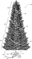
- FIG. 1 is a front perspective view of a modular, lighted artificial tree, according to an embodiment of the claimed invention
- FIG. 2 is a front view of the tree of FIG. 1 , with multiple branches removed;
- FIG. 3 is a block diagram of an electrical connection and wiring assembly of the modular, lighted artificial tree of FIG. 1 ;
- FIG. 4 depicts a wiring layout of a “single-wire” light string, according to an embodiment of the present invention
- FIG. 5 depicts a wiring layout of a “twisted-pair” light string of the prior art
- FIGS. 6-12 depict an embodiment of an electrical connector system having a central electrical terminal, according to an embodiment of the claimed invention
- FIGS. 13-14 depict the electrical connector system of FIGS. 6-12 as positioned in a tree trunk, according to an embodiment of the claimed invention
- FIGS. 15-20 depict another embodiment of an electrical connector system, according to an embodiment of the claimed invention.
- FIGS. 21-22 depict the electrical connector system of FIGS. 15-19 as positioned in a tree trunk, according to an embodiment of the claimed invention
- FIGS. 23-28 depict another electrical connector system, according to an embodiment of the claimed invention.
- FIGS. 29-36 depict an electrical connector system that includes four electrical terminals per connector, according to an embodiment of the claimed invention.
- FIG. 37 depicts an electrical schematic of an electrical wiring harness and connection system positioned in portions of the tree of FIG. 1 , according to an embodiment of the claimed invention
- FIG. 38 depicts a light string of the tree of FIG. 1 , according to an embodiment of the claimed invention.
- FIG. 39 depicts the light string of FIG. 38 as attached to a branch of the tree of FIG. 1 , according to an embodiment of the claimed invention.
- Embodiments of the claimed invention include lighted artificial trees with a variety of unique features, including mechanical and electrical trunk connection systems, multi-terminal electrical connectors, trunk wiring harnesses, and “single-wire” light strings.
- Modular tree 100 includes base portion 102 , first lighted tree portion 104 , second lighted tree portion 106 , and third lighted tree portion 108 .
- modular tree 100 may include more tree portions, such as a fourth tree portion, or may include fewer lighted tree portions.
- the depicted embodiment of modular tree 100 includes light strings, as described further below, but in other embodiments, modular tree 100 is not a lighted tree.
- Base portion 102 as depicted includes multiple legs 110 connected to a central trunk-support portion 112 .
- trunk support portion 112 may be generally cylindrical to receive and support first tree portion 104 .
- Base portion 102 may include an optional base-trunk portion 114 extending upwardly from trunk support portion 112 to form a portion of a trunk of tree 100 .
- base portion 102 may comprise other configurations capable of supporting and aligning tree portions 104 , 106 , and 108 in a steady, upright manner.
- Such alternate embodiments include a base portion having more or fewer legs 110 , an integrated structure with an opening for receiving first lighted tree portion 104 , and other such embodiments.
- modular tree 100 is depicted in an assembled configuration, with multiple branches and light strings removed for illustrative purposes.
- first lighted tree portion 104 includes first trunk portion 120 , multiple branches 122 , and one or more first light strings 124 .
- First trunk portion 120 as depicted comprises a generally cylindrical, hollow structure including trunk body 121 having a first end 123 , second end 125 , outside wall 126 , and one or more branch-support rings 127 .
- First trunk portion 120 in an embodiment, also defines multiple openings 166 in wall 126 .
- Branch-support rings 127 include multiple branch receivers 128 extending outwardly and away from trunk portion 120 .
- branch receivers 128 define a channel for receiving a trunk end of a branch 122 .
- Each branch 122 generally includes primary branch extension 130 and may also include multiple secondary branch extensions 132 extending away from branch extension 130 .
- Branch 122 is connected to trunk portion 120 at a branch receiver 128 at trunk-end 134 .
- branches 122 include strands 136 simulating the needles found on natural pine or coniferous trees.
- Strands 136 are attached to branch frame 135 , which in some embodiments comprises a solid-core frame, such as a metal rod, wire, multiple twisted wires or rods, or similar such materials.
- frame 135 may be hollow.
- Trunk ends of branches 122 may be bent or otherwise formed to define a loop or circular opening such that trunk end 134 of branch 122 may be secured to branch receiver 128 by way of a pin (not depicted) extending through branch receiver 128 and the loop formed at trunk end 134 of branch 122 .
- a branch 122 may be allowed to pivot about the pin and branch receiver 128 , allowing tree portion 104 to collapse to a smaller envelope size for convenient storage.
- Other embodiments may employ other means to attached branches to trunk sections.
- First light string 124 includes light string wiring 140 and a plurality of lighting element assemblies 142 .
- Each lighting assembly element 142 includes housing 144 and lighting element 146 .
- Lighting elements 146 may comprise incandescent bulbs, light-emitting diodes (LEDs), a combination thereof, or any of other known types of light-emitting elements.
- lighting elements 146 may be electrically connected in parallel, series, or a combination of series and parallel, to form a parallel-connected, series-connected, parallel-series connected, or series-parallel connected first light string 124 .
- first light string 124 is affixed to one or more branches 122 of lighted tree portion 104 via multiple clips 150 .
- a proximal end 152 of light string 124 may be connected to outside wall 126 of first trunk portion 120 by a connector or clip as described further below, or may be inserted through an opening 166 in wall 126 into an interior space defined by first trunk portion 120 and trunk body 121 .
- first lighted tree portion 104 includes a plurality of first light strings 124 .
- first light strings 124 may be substantially the same, for example, a series-parallel connected light string having 100 lighting element assemblies 142 .
- first lighted tree portion 104 may include first light strings 124 having a particular configuration and other first light strings 124 having another, different configuration.
- first light strings 124 located closer to base portion 102 may be longer in length with more light emitting assemblies 142
- first light strings 124 further from base portion 102 may be relatively shorter in length, with fewer light emitting assemblies 142 .
- first lighted tree portion 104 may include only a single light string 124 .
- Second lighted tree portion 106 adjacent first lighted tree portion 104 , is similar to lighted tree portion 104 and includes second trunk portion 160 , multiple branches 122 and one or more second light strings 162 .
- Second trunk portion 160 as depicted also comprises a generally cylindrical, hollow structure including trunk body 161 having a first end 163 , a second end 165 , outside wall 164 , and one or more branch-support rings 127 .
- First trunk portion 120 also defines multiple openings 166 in wall 164 .
- trunk portion 160 may have a trunk diameter that is substantially equal to a trunk diameter of first trunk portion 120 , while in other embodiments, may have a trunk diameter that is different from that of the first trunk portion.
- a trunk diameter of second trunk portion 160 is slightly less than a trunk diameter of first trunk portion 120 at an end such that that trunk 116 has a somewhat tapered look.
- second light strings 162 may comprise any combination of series-connected, series-parallel, parallel-series, or parallel-connected individual or groupings of lighting element assemblies 142 .
- Third lighted tree portion 108 adjacent to second lighted tree portion 106 includes third trunk portion 180 , branches 122 , and one or more third light strings 182 .
- a diameter of third trunk portion 180 may be somewhat smaller in diameter than a diameter of second lighted tree portion 108 .
- third trunk portion 180 comprises a relatively smaller diameter pipe-like body portion 184 including lower end 185 , upper end 186 , trunk wall 187 , and defining top opening 188 (see also FIGS. 3 and 4 ).
- third trunk portion 180 may also not include branch-support rings 127 , as branches 122 of third lighted tree portion 108 may be somewhat shorter in length than branches 122 of second lighted tree sections 106 and may be directly connected to body portion 184 of third trunk portion 180 .
- Third light string 182 includes wiring 190 and multiple lighting element assemblies 142 . Similar to first light strings 124 , third light strings 182 may comprise any combination of series-connected or parallel-connected individual or groups of lighting element assemblies 142 .
- third light string 182 emerges from top opening 188 such that a portion of third light string 182 is within an interior space defined by third trunk portion 180 .
- third light string 182 may be connected via an electrical connector at opening 188 .
- third light string is mechanically connected to trunk portion via a connector at wall 186 of third trunk portion 180 , or may be received in part by an opening (not depicted) in wall 186 .
- third light string 182 may be an extension of second light string 162 .
- electrical connection and wiring harness assembly 200 includes base portion electrical connection and wiring harness subassembly 202 , first tree portion electrical connection and wiring harness subassembly 204 , second tree portion electrical connection and wiring harness subassembly 206 , and third electrical connection and wiring harness 208 .
- Electrical connection and wiring harness assembly 200 also includes first electrical connector system 210 , second electrical connector system 212 and third electrical connector system 214 , electrically connecting base 102 to first tree portion 104 , first tree portion 104 to second tree portion 106 , and second tree portion 106 to third three portion 108 .
- base electrical connection and wiring harness subassembly 202 includes power cord 216 , first polarity wiring 218 having one or multiple wires, second polarity wiring 220 , also having one or multiple wires, electrical connector 222 , which in an embodiment comprises a female connector. Electrical connector 222 includes two or more electrical terminals 223 and 225 electrically connected to wires 220 and 218 , respectively.
- power cord 216 connects to wiring harness subassembly 204 and/or electrical connector 230 directly in a simplified electrical system.
- all or portions of base wiring harness 202 are positioned within trunk body 121 .
- First tree portion electrical connection and wiring harness subassembly 204 includes electrical connector 230 , wire set 232 having first polarity wire 232 a and second polarity wire 232 b , and electrical connector 222 .
- electrical connector 222 is substantially the same as connector 222 of base portion connector 222 .
- Electrical connector 222 includes two or more terminals 223 and 225 electrically connected to wires 232 a and 232 b , respectively. In another embodiment, the connectors differ.
- Electrical connector 230 in the embodiment is a male electrical connector.
- Electrical connector 230 includes two or more terminals 231 and 233 electrically connected to wires 232 a and 232 b , respectively.
- Second tree portion electrical connection and wiring harness subassembly 206 includes male electrical connector 230 , wire set 234 having first polarity wire 234 a and second polarity wire 234 b , and female electrical connector 222 .
- electrical connector 222 is substantially the same as connector 222 of base portion connector 222 , with terminals 223 and 225 electrically connected to wires 234 a and 234 b , respectively.
- the connectors differ.
- Male electrical connector 230 includes electrical terminals 231 and 233 electrically connected to wires 234 a and 234 b , respectively.
- Third tree portion electrical connection and wiring harness subassembly 208 includes electrical connector 230 and wire set 236 .
- each male/female connecting pair 222 / 230 the position of each connector could be reversed such that, for example, subassembly 202 includes male connector 230 rather than female connector 222 , and the male and female connectors on subassembly 204 are reversed from top to bottom.
- base portion electrical connection and wiring harness subassembly 202 plugs into first tree portion electrical connection and wiring harness subassembly 204 , which plugs into second tree portion electrical connection and wiring harness subassembly 206 , and which plugs into third electrical connection and wiring harness 208 to form tree electrical connection and wiring harness assembly 200 .
- an electrical connection is formed between subassemblies 202 , 204 , 206 , and 208 such that power may be transmitted from an external source via power cord 216 to the various wire sets 232 , 234 , and 236 , and distributed to multiple light sets 124 , 162 , and 182 of tree 100 .
- tree 100 may only include light strings of one electrical configuration type, e.g., all light strings have series connected lighting elements, or all light strings have parallel, or all have parallel-series/series-parallel.
- first light string 124 is a “parallel” configured light string, such that all lighting elements 146 of lighting assemblies 142 are electrically connected in parallel.
- tree 100 includes light string 124 a which as depicted includes series-connected lighting elements 146 , though in other embodiments, light string 124 a may be a series-parallel configuration.
- Each light string 124 , 162 , or 182 is electrically connected to a wiring harness of a tree portion. Electrical connection may be made within a trunk body, or outside a trunk body. In an embodiment, wiring of a light string may directly connected to a main wire using an electrical connector, to make a wire joint. In other embodiments, wires of light strings are integrated with the wiring harnesses, as described further below, such that wire joints are avoided.
- Light string 124 a as depicted is a “single-wire” light string (referred to as “single wire” as in many embodiments, only one wire having an insulator and a conductor, electrically connect any two lamp holders of a lighting element 142 , as will be described further below.
- a first wire 143 electrically connects a first lighting element 146 a to a first bus wire of wiring 234
- a second wire 145 connects lighting element 146 a to lighting element 146 b .
- a “single” wire electrically and mechanically joins the two lighting elements 146 a and 146 b .
- a last single wire 147 connects last lighting element 146 z to a second bus wire of wiring 234 to complete an electrical series circuit.
- This configuration allows first wire 143 to be connected to wiring 234 and tree portion 104 at a location different from the location that last wire 147 connects to wiring 234 and to tree portion 104 , if desired.
- light string 124 a may be distributed amongst multiple branches 130 , including branches that may be at different heights along tree portion 104 , branches adjacent one another at the same height, branches opposite one another, and so on, without having to bring last wire 147 back to a point close to, or adjacent to, first wire 143 .
- light string 124 a spans more than one tree portion, with an electrical connector joining a first portion of the light string 124 a (associated with first tree portion 104 ) and a second portion of the light string 124 a (associated with second tree portion 106 ).
- FIGS. 4 and 5 an embodiment of a single-wire construction light string 124 is depicted in FIG. 4 , and a traditional twisted pair wire configuration is depicted in FIG. 5 .
- light string 124 a includes a first lead wire 143 and a last return wire 147 .
- first wire 143 may be located at a first location of tree 100
- last wire 147 may be located at a different location of tree 100 .
- first wire 143 and last wire 147 are adjacent one another at the trunk.
- lead wire 143 may be twisted with return wire 147 , but a lead or return wire is not intertwined with other intermediate wires 145 .
- a twine, false wire, or other string-like portion may be intertwined with first, intermediate, and last wires to provide pull strength to light string 124 a .
- no such additional string-like portion is added to single-wire light string 124 a.
- a prior art light string 24 includes a last wire 147 , often referred to as an electrical “return wire”, that is intertwined with the other single wires of light string 24 , including first wire 143 and intermediate wires 145 .
- the twisting of the return wire between lighting elements 146 and intermediate wires 145 strengthens the mechanical coupling of lighting element assemblies 142 . If a pulling force is applied to wires between lighting element assemblies 142 (and lighting elements 146 ), it is less likely that wires will be pulled out of, or disengage from, lamp holders of lighting element assemblies 142 when the twisted-pair construction is used.
- electrical connector pairs 222 and 333 are configured for use with two-bus, or two main wire wiring harnesses (such as wiring harness subassemblies 232 having a first polarity bus/main wire 232 a and a second polarity bus/main wire 232 b ), and in other embodiments, are configured for use with wiring harnesses that include more than two bus wires (see also FIG. 37 ).
- each electrical connector 222 may be connected to its corresponding electrical connector 230 independent of a rotational alignment of the two electrical connectors, and/or independent of a rotational alignment between two trunk bodies, to make an electrical connection between electrical connectors such that a user does not need to be concerned with rotational alignment about an Axis A of individual tree portions when assembling tree 100 .
- reference numeral 222 will generally be used to refer to a first electrical connector as generically described and depicted in FIG. 3 , and which in some embodiments generally comprises a female electrical connector, and reference numeral 230 will generally be used to refer to a second electrical connector, which in some embodiments generally comprises a male electrical connector.
- an embodiment of an electrical connection system, system 300 is depicted.
- Electrical connection system 300 is configured to be utilized with either direct current (DC) power or alternating (AC) power.
- DC direct current
- AC alternating
- electrical connection system 300 is particularly suited for safely providing AC power to tree 100 .
- female electrical connector 222 and male electrical connector 230 may be connected in any of a plurality of rotational configurations, ensuring a high-quality electrical connection not prone to arcing that is easy to connect by a user.
- System 300 includes female or first electrical connector 222 and male or second electrical connector 230 .
- electrical connector 222 includes body 306 , center projection 308 , and defines annular cavity 310 , and outside surface 311 . Electrical connector 222 also includes first electrical contact or terminal 316 and 318 .
- body 306 comprises a non-conducting material and comprises a generally cylindrical shape, having a circular cross section, so as to fit into a trunk body, such as trunk body 121 .
- body 306 comprises other shapes adapted to fit into trunk bodies having non-circular openings.
- body 306 defines recess 315 at an exterior. Recess 315 may be used to locate and secure body 316 in a trunk body that includes a corresponding projection or detent inside the trunk body and configured to fit into recess 315 . In another embodiment, recess 315 is used merely to initially locate body 315 through an opening in a trunk body.
- first electrical terminal 316 (analogous to terminal 225 of FIG. 3 ) comprises a ring which may be cylindrical as depicted, or a band, comprising a conductive material.
- terminal 316 comprises a flat ring defining a flat planar surface transverse to Axis A, rather than a cylindrical ring or band coaxial with Axis A.
- Electrical terminal 316 when assembled is electrically connected to a wire, such as wire 232 b .
- Electrical terminal 316 is seated into cavity 310 of body 306 , against an inside surface opposite projection 308 .
- terminal 316 comprises a smaller diameter and is adjacent projection 308 .
- Second electrical terminal 318 (analogous to terminal 223 of FIG. 3 ) comprises a conductive material and defines receiving cavity 319 . When assembled, second electrical terminal 318 is electrically connected to a wire or conductor, such as wire 232 a , and is insertable into a second cavity of body 306 .
- electrical terminal 318 When assembled into body 306 , in an embodiment, electrical terminal 318 is generally located central to contact 316 , such that the two contacts are concentric, coaxial, or share a common central axis, which in an embodiment, is also Axis A of tree 100 (see FIG. 1 ).
- electrical connector 230 includes body 312 , electrical terminal 322 and electrical terminal 324 .
- Body 312 in an embodiment, comprises a non-conductive material and also comprises a generally cylindrical shape with circular cross-section and to fit into a trunk body having a similarly shaped end opening.
- body 312 defines recess 315 at an exterior.
- Recess 315 may be used to locate and electrical terminal 316 in a trunk body that includes a corresponding projection or detent inside the trunk body and configured to fit into recess 315 .
- recess 315 is used merely to initially locate body 315 through an opening in a trunk body.
- terminal refers generally to an electrical terminal, connector, or other such conductive element in electrical contact with a conductor of a wire, and does not necessarily require termination of a wire.
- first electrical terminal 322 may comprise a blade shape, with an arcuate side and a flat side. In other embodiments, contact 322 may comprise two arcuate sides. In an embodiment, second-polarity contact 324 comprises a pin-like structure.
- contact 324 is configured to fit into contact 318
- contact 320 is configured to fit into cavity 310 , thereby contacting an inside surface of contact 316 with its arcuate side and/or an edge.
- lighted artificial trees may include many, many light strings and light elements
- the power required to light tree 100 may be significant. This may be especially true for trees such as tree 100 that may use incandescent bulbs, as opposed to LED bulbs as lighting elements.
- the use of AC power combined with a high-current draw increases the potential for arcing between electrical contacts of a tree 100 .
- Electrical connection system 300 enables safe electrical connections between modular tree sections by providing a significant distance between electrical contacts of a first polarity, such as electrical terminals 322 and 316 , and electrical contacts of a second polarity, such as electrical terminals 318 and 324 .
- insulating projection 308 separates the terminals of differing polarity so as to further prevent electrical arcing.
- electrical connector 222 is inserted into trunk body 121 having an end diameter d 1 ; male electrical connector 230 is inserted into trunk body 161 having an end diameter d 2 .
- electrical connector 230 is inserted a distance X into an end of trunk body 161 .
- electrical connector 222 is inserted into an end of trunk body 121 such that a top surface 326 of body 306 is even with a distal most end or tip 328 of trunk body 121 . As will be explained further, such a configuration allows both the coupling of the trunk bodies 121 and 161 and the coupling of the pair of electrical connectors 222 and 230 .
- Electrical connectors 222 and 230 are secured in their respective trunk bodies by any variety of means, including the use of fasteners that penetrate the trunk body and connector body, by mating recesses 313 and 315 to corresponding projections on an inside surface of the trunk bodies (e.g., snap fit), via a friction fit, through the use of an adhesive, or by other such means.
- trunk body 121 and trunk body 161 are aligned along Axis A. Trunk body 121 is then coupled to trunk body 161 via insertion of an end of trunk body 121 into an end of trunk body 161 .
- outside diameter d 1 of trunk body 121 is the same as, or slightly less than, inside diameter d 2 of trunk body 161 .
- a diameter of electrical connector 222 is slightly less than a diameter of electrical connector 230 .
- ends of trunk bodies 121 and 161 overlap in region 350 .
- This coupling causes electrical connector 222 to make electrical connection with electrical connector 230 such that electrical terminal 316 is in contact with terminal 322 and electrical terminal 318 is in electrical communication or contact with terminal 324 .
- electrical terminal 322 is received by annular cavity 310 , such that the arcuate side of terminal 322 makes electrical connection with an inside surface of band-like electrical terminal 316 ; pin-like terminal 324 is received by cavity 319 , such that terminal 324 makes electrical connection with terminal 318 .
- trunk bodies 121 and 161 may be aligned along Axis A, but can be rotated about Axis A in any rotational alignment, or in some embodiments, any of a plurality of rotational alignments, and brought together causing electrical connection to be made between electrical connectors 222 and 230 , and hence between tree portions 102 and 104 . Because of the cylindrical shapes of receiving contacts 316 and 318 , first trunk portion 120 may be aligned or rotated to any rotational position relative to trunk portion 160 about Axis A then the two trunk portions coupled together to make an electrical connection between tree sections.
- system 400 an alternate embodiment of previously-described system 300 , is depicted as system 400 .
- System 400 is similar to system 300 , with some exceptions.
- Electrical connector 230 includes two blade-like electrical contacts 322 , namely first electrical terminal 322 a and second electrical terminal 322 b .
- First electrical terminal 322 a is located somewhat off-center of a top surface of body 312 ;
- second electrical terminal is 322 b is located near a periphery of a top surface of body 312 . Both terminals project outwardly and away from body 312 .
- terminal 322 a includes arcuate side 337 a and flat side 339 a
- terminal 322 b includes arcuate side 327 b and flat side 339 b .
- neither terminal 322 a or 332 b is central to body 312 , and each terminal 322 a and 322 b are different distances from an outside edge of body 312 .
- Electrical connector 222 of system 400 is substantially the same as electrical connector 222 of system 300 , with the exception that a center cavity 419 is larger than system center cavity 319 , and electric terminal 418 is enlarged to form a band-like or ring-like electrical terminal. Electrical terminals 418 and 316 are concentric about a center axis of electrical connector 222 of system 400 .
- electrical connectors 222 and 230 of system 400 are seated in their respective trunk bodies 121 and 161 in a manner substantially the same as system 300 .
- electrical connectors 222 and 230 make electrical connection.
- electrical terminal 322 a fits into cavity 310 such that arcuate side 337 a makes contact with terminal 316 ; electrical terminal 322 b fits into cavity 419 such that arcuate side 337 b makes electrical contact with terminal 418 .
- system 400 does not require any particular rotational alignment between electrical connectors, trunk bodies, or tree portions, to make electrical connection.
- Connector system 500 includes pairs of electrical terminals that are concentric to one another, and coaxial about a central axis when electrically connected.
- Electrical connector 222 of system 500 comprises body 502 , first electrical terminal 504 , and second electrical terminal 506 .
- Body 506 also defines a generally planar annular top surface 508 and a generally planar annual inner surface 510 .
- Top surface 508 in an embodiment forms a parallel plane with inner surface 510 .
- Body 506 also defines cavity 512 having a cavity portion 514 .
- electrical terminal 504 comprises a generally circular band 504 similar to other band-like terminals described above, including electrical terminal 316 . Electrical terminal 504 is located at least in part in cavity 512 , with an inside surface confronting a center of cavity 512 .
- electrical terminal 506 forms a generally cylindrical shape adapted to receive a pin-like terminal of electrical connector 230 , as described further below.
- electrical terminal 506 is recessed into body 502 such that top end of terminal 506 is below a plane formed by top surface 508 .
- Electrical terminal 506 as depicted is located along a central axis of body 506 , and is generally coaxial with electrical contact 504 .
- Electrical connector 230 of system 500 comprises body 520 , first electrical terminal 522 , and second electrical terminal 524 .
- Body 520 also defines a generally-planar first annular surface 526 , projection 528 with second generally-planar annular surface 530 .
- Projection 528 projects outwardly and away from body 520 and surface 526 in a tiered, or step-like fashion.
- First surface 526 in an embodiment forms a plane generally below and parallel with second surface 530 .
- First electrical terminal 522 in an embodiment comprises a pin-like structure projecting outwardly and away from body 520 and along a central axis of connector 230 .
- Second electrical terminal 524 is an annular, band-like, or ring-like structure that is partially embedded in body 520 , in an embodiment, and projects upwardly and away from surface 526 , such that a portion of conductive terminal 524 is exposed.
- Advantages of system 500 include increased contact area between the two band-like electrical terminals 504 and 524 and a strengthened mechanical connection between connectors 222 and 230 due in part to the insertion of projection 528 into cavity 512 .
- connection systems 300 - 500 are depicted as being adapted for two main/bus-wire wiring harnesses and subassemblies as depicted in FIG. 3 .
- the electrical connectors and systems of the claimed invention may be adapted to cooperate with wiring harnesses and subassemblies having more than two main wires.
- One such embodiment is described below with respect to FIGS. 29-36 .
- a tiered electrical connector system 600 is depicted.
- system 600 is configured to connect to four-wire wiring harnesses and subassemblies, though it will be understood that system 600 could be configured to have additional electrical terminals to connect with wiring harnesses having more than four wires.
- system 600 includes tiered electrical connector 222 and tiered electrical connector 230 .
- Tiered electrical connector 222 comprises body 602 and cylindrical or band-like electrical terminal set 616 , including terminals 616 a , 616 b , 616 c , and 616 d . Tiered electrical connector 222 also defines a tiered cavity 604 .
- Body 602 defines top, generally planar annular surface 606 , and a plurality of tiered, generally planar and annular surfaces within tiered cavity 604 .
- Tiered surfaces within cavity 604 include surface 608 , 610 , and 612 .
- Surfaces 606 , 608 , 610 , and 612 form decreasingly smaller annular rings as a center of connector 222 is approached. Further, planes formed by surfaces 606 , 608 , 610 and 612 are generally parallel.
- Terminal set 616 comprises the set of concentrically arranged cylindrical electrical terminals 616 a , 616 b , 616 c , and 616 d , each having an increasingly larger diameter, and connected to wires 632 a , 632 b , 632 c , and 632 d , respectively.
- central terminal 616 a is a first polarity, e.g., neutral
- terminals 616 b, c , and d comprise a second polarity, e.g., positive, “live” or “hot”.
- two terminals comprise a first polarity
- two terminals comprise a second polarity.
- Tiered electrical connector 230 comprises body 640 , electrical terminal 324 , and cylindrical terminal set 642 comprising electrical terminals 642 a , 642 b , and 642 c.
- Tiered body 640 forms first tier 644 , second tier 646 and third tier 648 .
- Tiered body 640 and its respective tiers also define annular surfaces 650 , 652 , 654 and 656 .
- third tier 648 is furthest from surface 650 ; second their 646 is second furthest from surface 650 ; and first tier is closest to surface 650 .
- each tier has approximately the same tier height, defined as a vertical distance from a plane of one tier to a plane of an adjacent tier.
- Terminal set 642 comprises the set of concentrically arranged cylindrical electrical terminals 642 a , 642 b , and 642 c each having an increasingly larger diameter, and connected to wires 632 b , 632 c , and 632 d , respectively.
- central terminal 324 is a first polarity, e.g., neutral
- terminals 634 a, b , and c comprise a second polarity, e.g., positive, “live” or “hot”.
- two terminals comprise a first polarity
- two terminals comprise a second polarity.
- tiered cavity 604 receives a portion of electrical connector 230 , including tiers 644 , 646 , and 648 and portions of their respective electrical terminals 642 a , 642 b , and 642 c .
- surfaces 650 , 652 , 654 , and 656 of electrical connector 230 are adjacent, and in some embodiments, in contact with, surfaces 606 , 608 , 610 and 612 , respectively, of electrical connector 222 . As such, a secure mechanical fit is formed between electrical connector 222 and electrical connector 230 .
- Terminal 316 a receives terminal 324 , making an electrical connection between the two terminals and between their respective wires 632 b and 634 b .
- terminals 316 a and 324 may be exchanged for terminals similar to 418 and 322 a of system 400 .
- an outside surface of terminal 642 a contacts in inside surface of terminal 316 b to make an electrical connection between wires 632 a and 634 a ; an outside surface of terminal 642 b contacts in inside surface of terminal 616 c to make an electrical connection between wires 632 c and 634 c ; and an outside surface of terminal 642 c contacts in inside surface of terminal 616 d to make an electrical connection between wires 632 d and 634 d .
- each of terminals 324 , 642 a , 642 b , and 642 c have outside diameters that are approximately the same size as their corresponding mating terminals 616 a , 616 b , 616 c , and 616 d , respectively such that each terminal pair makes surface contact as described above.
- connection of the terminal sets results in electrical connection between the respective wire sets 632 and 634 , such that power may be provided from one tree portion to another.
- tiered electrical connectors 222 and 230 result in a superior mechanical connection, electrical connections between multiple pairs of electrical terminals within a relatively small space is made with minimal risk of arcing between terminals of disparate polarity.
- tiered electrical connectors 222 and 230 are implemented in tree 100 .
- Tree portions 104 , 106 , and 108 are depicted less branches, branch rings and light strings for the sake of more clearly illustrating the advantageous electrical connection system of tree 100 .
- tree portion 104 includes trunk body 121 , power cord 216 , and wiring harness subassembly 604 .
- Tree portion 106 includes trunk body 161 and wiring harness subassembly 606 ;
- tree portion 108 includes trunk portion 184 and wiring harness subassembly 608 with wire set 638 .
- wiring harness subassemblies 604 , 606 , and 608 comprise 4-wire wiring harness subassemblies with two electrical polarities, though it will be understood that in other embodiments, wiring harness subassemblies 604 , 606 , and 608 could comprise harnesses that are based on more than 4-wires and two electrical polarities.
- Wiring harness subassembly 604 includes electrical connector 650 , primary wire set 632 comprising main/bus wires 632 a , 632 b , 632 c , and 632 d , first hub 652 , light string wire set 654 , light string wire set 656 , second hub 658 , light string wire set 660 , light string wire set 662 , and tiered electrical connector 222 .
- electrical connector 650 receives first polarity power wire 218 , electrically connecting it to bus wires 632 a and 632 b , and receives second polarity power wire 220 , electrically connecting it to bus wires 632 c and 632 d .
- power cord 216 is adapted to plug into an AC power supply, and may include a fuse.
- Electrical connector 650 may also include an in-line power fuse 633 , as depicted. It will be understood that electrical connectors 222 and 230 may also include in-line fuses 733 inside their respective bodies to provide protection to tree 100 in the event of a power surge, short or other such situation.
- electrical connector 650 may include a transformer for converting AC power to DC power.
- bus wire 632 a and 632 d extend from electrical connector 650 through trunk body 121 to tiered electrical connector 222 , thusly providing power to electrical connector 222 .
- bus wire 632 a electrically connects to conductor 670 and bus wire 632 d electrically connects to conductor 672 , thusly providing power to hub 658 .
- bus wires 632 b and 632 c are electrically connected to hub 652 , thereby providing power to hub 652 .
- hub 652 includes terminal block 674 and 676 electrically connected to bus wires 632 b and 632 c .
- Terminal blocks 674 and 676 are electrically connected to wire sets 656 and 654 , respectively.
- each wire of wire set 656 including wire 656 a
- each wire of wire set 654 including wire 654 a is electrically connected to second polarity power wire 220 .
- terminal blocks 674 and 676 each distribute power to five individual wires, in an embodiment, such that five light strings may be powered by hub 652 .
- hub 652 may provide power to more or fewer light strings 124 , depending on the number of light strings desired on tree 100 .
- each wire of wire set 656 terminates at a light string wire connector 678 , for example, wire 656 a terminates at light string wire connector 678 a ; and each wire of wire set 654 terminates at a light string wire connector 680 , for example, wire 654 a terminates at light string wire connector 680 a .
- Light strings 124 (see also FIGS. 4 and 38 ), including light strings 124 a , are electrically connected to light string wire connectors 678 and 680 , thusly receiving power when power cord 216 receives power from an external power source.
- wires 654 and 656 may not include light string wire connectors 678 and 680 , but rather, may be integrated with their corresponding light strings, forming the first and last wires, respectively, of their corresponding light string.
- Hub 652 in an embodiment comprises a printed circuit board enclosed in a housing (not depicted).
- the hub housing is conformal to trunk 121 , which in an embodiment means that the hub housing is generally cylindrical.
- Hub 658 is substantially the same as hub 652 , receiving power from electrical connector 222 and/or conductors 670 and 672 , and distributing power to wire sets 660 and 662 for powering light strings 124 (not shown).
- Wiring harness 604 provides a number of advantages relating to wire management and organization.
- a first quantity of light strings 124 are powered by light string wires that are connected to first hub 652 and electrical connector 650 , such that only those wire sets 654 and 656 , extending upwardly from a bottom of trunk body 121 , towards a center of trunk body 121 , connect to, and power, the first quantity light strings 124 of tree portion 104 .
- the first quantity of light strings 124 is generally attached to a lower portion of tree portion 104 .
- Bus wires 632 a and 632 d extend upwardly from connector 650 to connector 222 , then wire sets 660 and 662 , used to power the remaining, second portion of light strings 124 , extend axially downward towards a center of trunk body 121 .
- the second quantity of light strings 124 are generally attached to tree portion 100 at an upper part of tree portion 104 .
- Such a wiring layout maximizes use of the space within trunk cavity 121 by evenly distributing the individual wires powering light strings 124 .
- a bulk of wiring would be located at a lower portion of trunk body 121 , making it more difficult to fit the wiring within the trunk cavity, and creating more opportunities for arcing, shorting, and increased electromagnetic interference.
- Wiring harness subassembly 606 of tree portion 106 with its tiered connector 230 distributes power to lights 162 (see FIG. 2 ), in a manner similar to wiring harness subassembly 604 .
- Wiring harness subassembly 608 of tree portion 108 may be a simplified wiring harness as depicted, due, in part, to the fewer number of light strings powered, and lesser size and weight.
- tree portion 106 couples with tree portion 104 independent of a rotational alignment of trunk bodies or tree portions, such that a user may easily assemble tree 100 , without a need to rotationally align the connectors.
- tree portion 106 includes female electrical connector 690 that couples to male electrical connector 692 to electrically connect tree portions 106 and 108 .
- connector 690 and 692 are two-pin connectors that require one of two rotational alignments of tree portions 106 and 108 in order to be coupled. Due to the smaller size and weight of tree portion 108 , in some embodiments, such a two-pin or two-prong or keyed electrical connection system may not be burdensome for a user to accommodate and is presented to illustrate an alternate embodiment.
- one or more electrical controllers may be housed within trunk body 121 or 161 .
- such a controller would be electrically or communicatively coupled to hubs 652 / 658 and light strings 124 / 162 to control power to one or more light strings to create various visual effects including color changing, flashing, fading, and so on.
- Wiring harness subassembly with hubs 652 and 658 provide a number of additional advantages.
- One such advantage is that the electrical connection of the many light strings of tree 100 to a power supply can be made at one, two, or only a few locations.
- the use of a hub with terminal blocks for making the electrical connections ensures a uniform electrical connection, eliminating the need to crimp or solder individual light string wires to power wires.
- a “single-wire” light string 124 a for use with an embodiment of tree 100 including the embodiment of tree 100 depicted and described with respect to FIG. 37 , is depicted.
- Light string 124 a as depicted is substantially the same as light string 124 a as depicted and described with respect to FIG. 4 .
- FIG. 38 depicts additional details of light string 124 a.
- light string 124 a includes first or lead wire 143 with terminal 141 a , a plurality of lighting assemblies 142 , a plurality of intermediate wires 145 , last or return wire 147 with terminal 141 b.
- Each lighting assembly 142 includes lighting element 146 and lamp holder 149 .
- Each lamp holder 151 may include lamp lock 151 which locks an adapter or base connected to lighting element 146 to lamp holder 151 so as to prevent lighting element 146 from being accidentally removed from lamp holder 151 .
- Lamp lock device 151 may also serve to orient lighting element 146 to lamp holder 149 , such that the electrical polarity of lighting element 146 matches the electrical polarity of lamp holder 149 .
- every lamp holder is a two-wire lamp holder in that the lamp holder is configured to receive not more than two wires. Such an embodiment is made possible with the single-wire construction, including a single-wire construction with a single series circuit.
- Each intermediate wire at a first end is inserted into a lamp holder 149 to make an electrical connection to a lead of a lighting element 146 , and at a second end is inserted into a another lamp holder 149 to make an electrical connection with another lighting element 146 , as part of the series connection.
- neither first wire 143 nor last wire 147 are twisted about intermediate wires 145 .
- single-wire light string 124 a also does not include any other supporting strands woven about intermediate wires 145 .
- neither first wire 143 nor last wire 147 are twisted or wrapped about any of the intermediate wires. In another embodiment, neither first wire 143 nor last wire 147 are twisted about all of the intermediate wires, but one of wire 143 or 147 may be twisted about some of the intermediate wires, which in an embodiment, means less than half of the intermediate wires 145 .
- terminals 141 a and 141 b may be connected to terminals 678 a and 680 a of wiring harness 604 so as to be electrically connected to a power source.
- lead wires 143 and 147 are integrated into wiring harness subassembly 604 .
- terminals 678 a and 680 a may comprise terminals of the type depicted as 141 a and 141 b .
- Terminals 141 a and 141 b may be terminals adapted to be received by a lamp holder 149 .
- an electrical connection between an external portion of wiring harness 604 connects to light string 124 a at a standard lamp holder 149 , thereby avoiding the use of other types of connectors, including connectors at a trunk wall.
- first wire 143 is a wire of the wiring harness
- last wire 147 is also a wire of the wiring harness.
- light string 124 a of the claimed invention is depicted as attached to a branch 122 and branch extension 130 .
- return wire 147 is twisted about a portion of branch frame 135 and terminates at last lamp holder 149 z .
- intermediate wires 145 may be twisted about one another as shown (recalling that a traditional twisted pair light string twists intermediate wires with either a lead wire or a return wire). In other embodiments, intermediate wires 145 may not be twisted about one another.
- the resulting effect of not having a return wire 147 twisted about all intermediate wires 145 is that less overall wire may be used since a return wire of light string 124 a will be shorter than a return wire that twists about all intermediate wires. Not only does this save in manufacturing costs, but also improves the aesthetic appearance of tree 100 .
Abstract
Description
Claims (20)
Priority Applications (1)
| Application Number | Priority Date | Filing Date | Title |
|---|---|---|---|
| US16/725,974 US11013355B2 (en) | 2012-05-08 | 2019-12-23 | Modular tree with electrical connector |
Applications Claiming Priority (7)
| Application Number | Priority Date | Filing Date | Title |
|---|---|---|---|
| US201261643968P | 2012-05-08 | 2012-05-08 | |
| US13/836,026 US9044056B2 (en) | 2012-05-08 | 2013-03-15 | Modular tree with electrical connector |
| US14/725,972 US9526286B2 (en) | 2012-05-08 | 2015-05-29 | Modular tree with electrical connector |
| US15/350,707 US10010208B2 (en) | 2012-05-08 | 2016-11-14 | Modular tree with electrical connector |
| US15/596,421 US10028607B2 (en) | 2012-05-08 | 2017-05-16 | Modular tree with electrical connector |
| US16/039,132 US10512354B2 (en) | 2012-05-08 | 2018-07-18 | Modular tree with electrical connector |
| US16/725,974 US11013355B2 (en) | 2012-05-08 | 2019-12-23 | Modular tree with electrical connector |
Related Parent Applications (1)
| Application Number | Title | Priority Date | Filing Date |
|---|---|---|---|
| US16/039,132 Continuation US10512354B2 (en) | 2012-05-08 | 2018-07-18 | Modular tree with electrical connector |
Publications (2)
| Publication Number | Publication Date |
|---|---|
| US20200196789A1 US20200196789A1 (en) | 2020-06-25 |
| US11013355B2 true US11013355B2 (en) | 2021-05-25 |
Family
ID=49548444
Family Applications (6)
| Application Number | Title | Priority Date | Filing Date |
|---|---|---|---|
| US13/836,026 Active 2033-08-17 US9044056B2 (en) | 2012-05-08 | 2013-03-15 | Modular tree with electrical connector |
| US14/725,972 Active US9526286B2 (en) | 2012-05-08 | 2015-05-29 | Modular tree with electrical connector |
| US15/350,707 Active US10010208B2 (en) | 2012-05-08 | 2016-11-14 | Modular tree with electrical connector |
| US15/596,421 Active US10028607B2 (en) | 2012-05-08 | 2017-05-16 | Modular tree with electrical connector |
| US16/039,132 Active US10512354B2 (en) | 2012-05-08 | 2018-07-18 | Modular tree with electrical connector |
| US16/725,974 Active US11013355B2 (en) | 2012-05-08 | 2019-12-23 | Modular tree with electrical connector |
Family Applications Before (5)
| Application Number | Title | Priority Date | Filing Date |
|---|---|---|---|
| US13/836,026 Active 2033-08-17 US9044056B2 (en) | 2012-05-08 | 2013-03-15 | Modular tree with electrical connector |
| US14/725,972 Active US9526286B2 (en) | 2012-05-08 | 2015-05-29 | Modular tree with electrical connector |
| US15/350,707 Active US10010208B2 (en) | 2012-05-08 | 2016-11-14 | Modular tree with electrical connector |
| US15/596,421 Active US10028607B2 (en) | 2012-05-08 | 2017-05-16 | Modular tree with electrical connector |
| US16/039,132 Active US10512354B2 (en) | 2012-05-08 | 2018-07-18 | Modular tree with electrical connector |
Country Status (1)
| Country | Link |
|---|---|
| US (6) | US9044056B2 (en) |
Cited By (1)
| Publication number | Priority date | Publication date | Assignee | Title |
|---|---|---|---|---|
| US11346510B2 (en) * | 2020-10-20 | 2022-05-31 | Steven Plissey | Decorative display of hollow-chambered translucent panels and LED strips |
Families Citing this family (53)
| Publication number | Priority date | Publication date | Assignee | Title |
|---|---|---|---|---|
| US9833098B2 (en) * | 2009-07-14 | 2017-12-05 | Loominocity, Inc. | Architecture for routing multi-channel commands via a tree column |
| US8454186B2 (en) | 2010-09-23 | 2013-06-04 | Willis Electric Co., Ltd. | Modular lighted tree with trunk electical connectors |
| US8298633B1 (en) | 2011-05-20 | 2012-10-30 | Willis Electric Co., Ltd. | Multi-positional, locking artificial tree trunk |
| US8863416B2 (en) | 2011-10-28 | 2014-10-21 | Polygroup Macau Limited (Bvi) | Powered tree construction |
| US8569960B2 (en) | 2011-11-14 | 2013-10-29 | Willis Electric Co., Ltd | Conformal power adapter for lighted artificial tree |
| US9157587B2 (en) | 2011-11-14 | 2015-10-13 | Willis Electric Co., Ltd. | Conformal power adapter for lighted artificial tree |
| US8876321B2 (en) | 2011-12-09 | 2014-11-04 | Willis Electric Co., Ltd. | Modular lighted artificial tree |
| US9179793B2 (en) | 2012-05-08 | 2015-11-10 | Willis Electric Co., Ltd. | Modular tree with rotation-lock electrical connectors |
| US10206530B2 (en) | 2012-05-08 | 2019-02-19 | Willis Electric Co., Ltd. | Modular tree with locking trunk |
| US9572446B2 (en) | 2012-05-08 | 2017-02-21 | Willis Electric Co., Ltd. | Modular tree with locking trunk and locking electrical connectors |
| US9044056B2 (en) * | 2012-05-08 | 2015-06-02 | Willis Electric Co., Ltd. | Modular tree with electrical connector |
| US20140293650A1 (en) * | 2013-03-01 | 2014-10-02 | Lauren Illumination, Llc | Component lighting system |
| US9439528B2 (en) | 2013-03-13 | 2016-09-13 | Willis Electric Co., Ltd. | Modular tree with locking trunk and locking electrical connectors |
| US9671074B2 (en) | 2013-03-13 | 2017-06-06 | Willis Electric Co., Ltd. | Modular tree with trunk connectors |
| US9593831B2 (en) | 2013-09-12 | 2017-03-14 | 1 Energy Solutions, Inc. | Artificial LED lighted Christmas tree |
| US9894949B1 (en) | 2013-11-27 | 2018-02-20 | Willis Electric Co., Ltd. | Lighted artificial tree with improved electrical connections |
| US8870404B1 (en) | 2013-12-03 | 2014-10-28 | Willis Electric Co., Ltd. | Dual-voltage lighted artificial tree |
| WO2015160866A1 (en) * | 2014-04-14 | 2015-10-22 | UCP International Co. Ltd | Display structure with modular electrical connector |
| US9883566B1 (en) | 2014-05-01 | 2018-01-30 | Willis Electric Co., Ltd. | Control of modular lighted artificial trees |
| US9402498B2 (en) * | 2014-06-27 | 2016-08-02 | National Tree Company | Safety grounded tree |
| US9362657B1 (en) * | 2015-02-13 | 2016-06-07 | Jetmax Lighting Industrial Co., Limited | Quick mount connector assembly of artificial Christmas tree |
| US9209546B1 (en) | 2015-02-17 | 2015-12-08 | Central Garden And Pet Company | Mechanical and electrical connector for artificial holiday tree poles |
| US9713205B2 (en) | 2015-02-18 | 2017-07-18 | 1 Energy Solutions, Inc. | Bidirectional LED light string |
| US9627364B2 (en) | 2015-02-18 | 2017-04-18 | 1 Energy Solutions, Inc. | Combined multicolored and white LED lamp |
| US9839315B2 (en) * | 2015-03-27 | 2017-12-12 | Polygroup Macau Limited (Bvi) | Multi-wire quick assemble tree |
| US10357071B2 (en) | 2015-11-18 | 2019-07-23 | Willis Electric Co., Ltd. | Combustion-resistant artificial tree |
| CN205376910U (en) * | 2015-12-25 | 2016-07-06 | 周志斌 | Assembled christmas tree |
| US10522270B2 (en) * | 2015-12-30 | 2019-12-31 | Polygroup Macau Limited (Bvi) | Reinforced electric wire and methods of making the same |
| US9960558B2 (en) * | 2016-03-04 | 2018-05-01 | Polygroup Macau Limited (Bvi) | Powered tree construction |
| US9907136B2 (en) | 2016-03-04 | 2018-02-27 | Polygroup Macau Limited (Bv) | Variable multi-color LED light string and controller for an artificial tree |
| US10982828B1 (en) | 2016-08-22 | 2021-04-20 | Willis Electric Co., Ltd. | Artificial tree with LED-based lighting systems |
| US10278254B2 (en) | 2016-12-02 | 2019-04-30 | Sterno Home Inc. | Illumination system with color-changing lights |
| US10441014B1 (en) | 2017-01-03 | 2019-10-15 | Willis Electric Co., Ltd. | Artificial tree having multiple tree portions with electrical connectors secured therein |
| US10288236B1 (en) | 2017-03-03 | 2019-05-14 | Willis Electric Co., Ltd. | Shapeable light string and methods for tree decoration |
| CN206524506U (en) * | 2017-03-17 | 2017-09-26 | 云梦云曦灯饰制品有限公司 | Combined power socket for artificial Christmas |
| US10615555B1 (en) | 2017-05-02 | 2020-04-07 | Seasonal Specialties, Llc | Central shaft power connector for lighted ornaments |
| US10333252B1 (en) | 2017-05-02 | 2019-06-25 | Seasonal Specialties, Llc | Central shaft power connector for lighted ornaments |
| USD925455S1 (en) | 2017-11-22 | 2021-07-20 | Seasonal Specialties, Llc | Power connector assembly for artificial tree lighting |
| US10683974B1 (en) | 2017-12-11 | 2020-06-16 | Willis Electric Co., Ltd. | Decorative lighting control |
| US10091843B1 (en) * | 2018-02-05 | 2018-10-02 | Jlj, Inc. | Christmas tree with DC outlets for powering LED light strings |
| US10989371B2 (en) | 2018-03-09 | 2021-04-27 | Blooming International Limited | Dual-color light emitting diode light strings |
| US10907781B2 (en) | 2018-03-09 | 2021-02-02 | Blooming International Limited | LED decorative lighting assembly having two parallel conductors and an insulating portion encapsulating portions of the conductors and a space there between |
| US10845036B2 (en) * | 2018-03-09 | 2020-11-24 | Blooming International Limited | Dual-color light strings |
| CN208226257U (en) * | 2018-05-23 | 2018-12-11 | 东莞市华阳灯饰有限公司 | It is a kind of can more piece connection adapter |
| CN110958731A (en) | 2018-09-21 | 2020-04-03 | 鸿盛国际有限公司 | Light emitting diode parallel circuit |
| US10845011B2 (en) * | 2018-12-25 | 2020-11-24 | Evergreen Tree Limited | Replaceable lighting system for artificial christmas trees and other decorations |
| US11300255B2 (en) | 2018-12-25 | 2022-04-12 | Evergreen Tree Limited | Replaceable lighting system for artificial Christmas trees and other decorations |
| CN111465133A (en) | 2019-01-21 | 2020-07-28 | 鸿盛国际有限公司 | Group-controlled light-emitting diode parallel circuit |
| US11424583B2 (en) | 2019-06-19 | 2022-08-23 | Blooming International Limited | Serially-connectable light string |
| CN112582516A (en) | 2019-09-27 | 2021-03-30 | 鸿盛国际有限公司 | Wire lamp packaging structure |
| US10973354B1 (en) | 2020-08-17 | 2021-04-13 | Chang Fu Tsai | Modular electrical distribution system for an illuminable decoration, and illuminable decoration with modular electrical distribution system |
| US11441766B2 (en) * | 2020-09-14 | 2022-09-13 | Ledup Manufacturing Group Limited | Tree pole with built-in individually controlled LED lighting system |
| US20220115815A1 (en) * | 2020-10-13 | 2022-04-14 | Ledup Manufacturing Group Limited | Tree pole connectors |
Citations (8)
| Publication number | Priority date | Publication date | Assignee | Title |
|---|---|---|---|---|
| US4020201A (en) * | 1976-02-11 | 1977-04-26 | Jeanne Marylyn Miller | Artificial tree |
| US20040090770A1 (en) * | 2002-11-06 | 2004-05-13 | Sylvain Primeau | Combination artificial tree-lighting arrangement |
| US20060164834A1 (en) * | 2005-01-21 | 2006-07-27 | Fang-Cheng Kao | Power distributor for christmas tree |
| US20070230174A1 (en) * | 2006-04-03 | 2007-10-04 | Hicks Larry O | Illuminated artificial tree |
| US8053042B1 (en) * | 2009-07-14 | 2011-11-08 | Jason Loomis | Artificial tree apparatus |
| US9402498B2 (en) * | 2014-06-27 | 2016-08-02 | National Tree Company | Safety grounded tree |
| US9700169B2 (en) * | 2014-09-18 | 2017-07-11 | Greenfields Christmas Tree Manufactory | Modularized artificial light tree |
| US9839315B2 (en) * | 2015-03-27 | 2017-12-12 | Polygroup Macau Limited (Bvi) | Multi-wire quick assemble tree |
Family Cites Families (527)
| Publication number | Priority date | Publication date | Assignee | Title |
|---|---|---|---|---|
| US438310A (en) | 1890-10-14 | Lamp-base | ||
| US1314008A (en) | 1919-08-26 | Liams | ||
| US735010A (en) | 1902-03-10 | 1903-07-28 | Arthur H Zahl | Christmas tree. |
| US860406A (en) | 1906-12-28 | 1907-07-16 | Frederick Luther Mcgahan | Fireproof christmas tree. |
| US1372777A (en) | 1920-05-17 | 1921-03-29 | William R Samuel | Holder for christmas-trees |
| US1495695A (en) | 1922-03-09 | 1924-05-27 | Laurence G Karr | Collapsible christmas tree |
| US1590220A (en) | 1924-02-26 | 1926-06-29 | Wurts Waldemar | Artificial tree and similar structure |
| US1536332A (en) | 1924-11-22 | 1925-05-05 | Monowatt Electric Imp Co Inc | Lamp socket for christmas-tree lighting |
| US1656148A (en) | 1926-04-05 | 1928-01-10 | Harris Mark | Artificial christmas tree |
| US1694974A (en) | 1926-08-26 | 1928-12-11 | Charles H Glover | Artificial christmas tree |
| US1974472A (en) | 1927-07-16 | 1934-09-25 | Emiel P Seghers | Decorative lighting for christmas trees |
| US1677972A (en) | 1927-08-03 | 1928-07-24 | Emanuel S Marks | Electrically-illuminated artificial tree |
| US1895656A (en) | 1932-02-03 | 1933-01-31 | Gadke William | Clip for attaching electric lights to christmas trees |
| US2025189A (en) | 1932-07-02 | 1935-12-24 | Hatfield Wire & Cable Co | Plug cap |
| US2050364A (en) | 1934-12-18 | 1936-08-11 | Westinghouse Electric & Mfg Co | Series lamp socket |
| US2112281A (en) | 1936-05-02 | 1938-03-29 | Starline | Grip for manila rope and the like |
| US2072337A (en) | 1936-05-05 | 1937-03-02 | Nofade Electric Corp | Safety lighting circuit |
| US2229211A (en) | 1937-12-22 | 1941-01-21 | John A Korengold | Electrical connector |
| US2188529A (en) | 1938-03-16 | 1940-01-30 | Corina Angelo | Artificial tree |
| US2186351A (en) | 1938-09-12 | 1940-01-09 | Stojaneck Paul | Semiartificial christmas tree |
| US2214046A (en) | 1938-12-02 | 1940-09-10 | John J Doran | Artificial tree |
| US2484813A (en) | 1945-06-06 | 1949-10-18 | John O Bower | Spun suture |
| US2466499A (en) | 1945-09-04 | 1949-04-05 | Sokolik Edward | Swivel for electric cables |
| US2563713A (en) | 1945-09-20 | 1951-08-07 | Bendix Aviat Corp | Electrical connector having resilient inserts |
| US2533374A (en) | 1946-03-25 | 1950-12-12 | John Deere Van Brunt Co | Dirt guard for grain drills |
| US2484596A (en) | 1947-09-27 | 1949-10-11 | Bell Telephone Labor Inc | Lamp socket for series lighting circuits |
| US2636069A (en) | 1949-01-04 | 1953-04-21 | Gilbert Margaret Doris | Pin-tap lamp socket |
| US2570751A (en) | 1949-08-24 | 1951-10-09 | Gen Electric | Lamp socket |
| US2857506A (en) | 1954-04-28 | 1958-10-21 | Dorothy C Minteer | Artificial illuminated tree |
| US2969456A (en) | 1954-12-22 | 1961-01-24 | Florence C Raymaley | Christmas tree lighting device |
| US2782296A (en) | 1955-02-07 | 1957-02-19 | Alfred E Walter | Clamp on christmas tree light |
| US2826845A (en) | 1955-03-30 | 1958-03-18 | Warren Christmas Trees Inc | Artificial christmas tree |
| US2806938A (en) | 1955-06-15 | 1957-09-17 | Grady R Henry | Illuminated rotating tree |
| US2863037A (en) | 1956-04-18 | 1958-12-02 | Cyrus E Johnstone | Electric coffee cup |
| US2826846A (en) | 1956-04-23 | 1958-03-18 | Warren Christmas Trees Inc | Artificial tree |
| US2910842A (en) | 1957-12-11 | 1959-11-03 | Sperry Rand Corp | Coupling |
| NL123417C (en) | 1958-02-28 | |||
| US2973546A (en) | 1958-07-24 | 1961-03-07 | Harvard Mfg Company | Plastic caster socket |
| US2932811A (en) | 1958-08-11 | 1960-04-12 | Paul P Abraham | Safety cover for electrical outlets |
| FR1215214A (en) | 1958-11-10 | 1960-04-15 | Jumo Soc Nouv Ets | Juxtaposed snap-in support arm for electrical equipment |
| US3120351A (en) | 1959-10-05 | 1964-02-04 | Walter B E Kirsten | Christmas tree light bulb mounting means |
| US3118617A (en) | 1960-03-18 | 1964-01-21 | Hellrich Tobias | Electrically illuminated artificial christmas tree |
| US2984813A (en) | 1960-07-14 | 1961-05-16 | Frankel Associates Inc | Lamp socket electrical connection |
| US3115435A (en) | 1960-12-28 | 1963-12-24 | Raylite Electric Corp | Decorative simulated christmas tree constructions |
| US3131112A (en) | 1961-02-20 | 1964-04-28 | Raylite Electric Corp | Molded plastic segmented trunk and branch holder means for simulated christmas trees |
| US3144375A (en) | 1961-02-24 | 1964-08-11 | Guy C Day | Artificial tree |
| US3214318A (en) | 1961-02-27 | 1965-10-26 | Snow Marvin | Artificial christmas tree |
| US3234073A (en) | 1962-04-26 | 1966-02-08 | Gerald L Raymond | Artificial tree |
| US3214579A (en) | 1963-03-04 | 1965-10-26 | Mario C Pacini | Christmas tree lighting systems |
| US3233207A (en) | 1964-02-21 | 1966-02-01 | Joseph M Ahroni | Decorative light |
| US3345482A (en) | 1964-06-29 | 1967-10-03 | Lou Shih-Woo | Electric shunt device |
| US3296430A (en) | 1964-10-01 | 1967-01-03 | Eckert William | Tree lighting system |
| FR1456535A (en) | 1965-06-23 | 1966-07-08 | Improvements in electrical contact sockets with inclined elastic wires, and in processes and machines for their manufacture | |
| US3286088A (en) | 1965-08-16 | 1966-11-15 | Joseph M Ahroni | Plug in light |
| US3409867A (en) | 1966-07-25 | 1968-11-05 | Efc Inc | Detachable electrical connectors |
| US3398260A (en) | 1966-08-29 | 1968-08-20 | Scovill Manufacturing Co | Cordless electric iron |
| NL136337C (en) | 1967-02-22 | |||
| US3504169A (en) | 1967-10-17 | 1970-03-31 | Barron H Freeburger | Electric light string kit |
| US3521216A (en) | 1968-06-19 | 1970-07-21 | Manuel Jerair Tolegian | Magnetic plug and socket assembly |
| US3522579A (en) | 1968-11-26 | 1970-08-04 | Ryosuke Matsuya | Socket for decorating light bulb and device for connecting the bulb to cords in the socket |
| US3640496A (en) | 1968-12-02 | 1972-02-08 | Southbourne Rubber Co Ltd | Plug or stopper for the open ends of tubular metal appliances |
| US3585564A (en) | 1969-01-08 | 1971-06-15 | Olav Skjervoll | Swiveling electrical connector |
| US3574102A (en) | 1969-02-18 | 1971-04-06 | Mr Christmas Inc | Collapsible artificial tree construction adapted for christmas decoration |
| US3616107A (en) | 1969-03-20 | 1971-10-26 | Hpe Inc | Sectionalized artificial tree structure with integral branch and collar combinations |
| GB1245214A (en) | 1969-04-29 | 1971-09-08 | Amp Inc | Improved tab receptacle electrical connector |
| US3571586A (en) | 1969-04-29 | 1971-03-23 | Hugh L Duckworth | An artificial christmas tree with integral lighting means |
| US3617732A (en) | 1969-11-19 | 1971-11-02 | Royal P Fisher | Artificial tree with an electrical illuminating system |
| US3594260A (en) | 1970-01-16 | 1971-07-20 | Percy Dieffenbach | Artificial shrubbery and method of manufacturing the same |
| US3603780A (en) | 1970-01-26 | 1971-09-07 | Kenneth C Lu | Artificial tree structure |
| US3806399A (en) | 1970-07-30 | 1974-04-23 | D Cocjin | Mechanical christmas tree manifested by its rotating motion and the undulation of its branches |
| US3728787A (en) | 1970-08-05 | 1973-04-24 | Molex Inc | Method of making a shielded cable connector |
| US3715708A (en) | 1970-10-21 | 1973-02-06 | Pace Inc | Electrical connector |
| US3663924A (en) | 1971-01-29 | 1972-05-16 | Matthew E Gerlat | Safety outlet |
| US3704366A (en) | 1971-09-03 | 1972-11-28 | Lawrence J Korb | Outdoor lighted artificial christmas tree |
| US3783437A (en) | 1971-10-07 | 1974-01-01 | Gen Electric | Lamp and socket for decorative string set |
| US3812380A (en) | 1972-04-10 | 1974-05-21 | G Davis | Control for christmas tree lighting |
| US3808450A (en) | 1972-04-10 | 1974-04-30 | G Davis | Christmas tree lighting control |
| US3748488A (en) | 1972-04-10 | 1973-07-24 | G Davis | Christmas tree lighting control |
| US3819459A (en) | 1972-04-24 | 1974-06-25 | B Wren | Asymmetric artificial christmas tree |
| US3764862A (en) | 1972-10-19 | 1973-10-09 | Fairchild Camera Instr Co | Lead frame for light-emitting diodes |
| US3862434A (en) | 1973-03-07 | 1975-01-21 | Davis George B Jun | Christmas tree lighting control |
| US3864580A (en) | 1973-03-19 | 1975-02-04 | Davis George B Jun | Christmas tree lighting control |
| US3971619A (en) | 1974-01-04 | 1976-07-27 | Rohrssen Donald J | Safe electrical connector |
| US3914786A (en) | 1974-04-19 | 1975-10-21 | Hewlett Packard Co | In-line reflective lead-pair for light-emitting diodes |
| US3970834A (en) | 1974-12-16 | 1976-07-20 | Marion Joseph Smith | Artificial tree |
| US4057735A (en) | 1975-01-21 | 1977-11-08 | Davis George B Jun | Christmas tree lighting control |
| US3985924A (en) | 1975-03-17 | 1976-10-12 | The Raymond Lee Organization, Inc. | Artificial Christmas tree |
| US4012631A (en) | 1975-05-12 | 1977-03-15 | Creager James J | Tree lighting assembly |
| US4045868A (en) | 1975-07-21 | 1977-09-06 | Elfab Corporation | Method of fabrication and assembly of electrical connector |
| US4125781A (en) | 1975-12-02 | 1978-11-14 | Davis George B Jun | Christmas tree lighting control |
| US4072857A (en) | 1976-05-10 | 1978-02-07 | Devicaris Guy A | Artificial tree |
| US4097917A (en) | 1976-06-07 | 1978-06-27 | Mccaslin Robert E | Rotatable light display |
| US4130678A (en) | 1976-10-21 | 1978-12-19 | Higgins James R | Collapsible artificial Christmas tree |
| US4109345A (en) | 1977-02-24 | 1978-08-29 | American Technical Institute, Inc. | Hinged branch holder |
| US4140823A (en) | 1977-04-01 | 1979-02-20 | Industrial Park Machine & Tool Co., Inc. | Foldable Christmas tree and branch holder therefor |
| US4153860A (en) | 1977-08-17 | 1979-05-08 | Frederick Vonick | Lighting control apparatus |
| US4161768A (en) | 1978-06-14 | 1979-07-17 | Caverzan Fred G | Artificial Christmas tree |
| US4203476A (en) | 1979-01-05 | 1980-05-20 | Dayco Corporation | Wire reinforced hose |
| US4215277A (en) | 1979-02-09 | 1980-07-29 | Robert I. Weiner | Sequencing light controller |
| US4262480A (en) | 1979-03-01 | 1981-04-21 | Frederick A. Lowenstein | Novelty yarn and method and apparatus of making same |
| US4248916A (en) | 1979-05-24 | 1981-02-03 | General Foam Plastics Corp. | Artificial christmas tree |
| US4343842A (en) | 1979-05-24 | 1982-08-10 | General Foam Plastics Corp. | Artificial Christmas tree |
| US4245875A (en) | 1979-06-18 | 1981-01-20 | Amp Incorporated | Heavy duty plug and socket |
| US4546041A (en) | 1979-07-30 | 1985-10-08 | General Electric Company | Corona-resistant wire enamel compositions and conductors insulated therewith |
| US4291075A (en) | 1979-10-29 | 1981-09-22 | Puleo Salvatore J | Bracket for artificial Christmas tree branches |
| US4273814A (en) | 1979-11-05 | 1981-06-16 | Noma Lites Canada Limited | Artificial shrubs of improved construction |
| US4340841A (en) | 1980-05-22 | 1982-07-20 | General Electric Company | Internal shunt for series connected lamps |
| GB2112281A (en) | 1981-10-09 | 1983-07-20 | Peter Albert Sullivan | Decorative Christmas tree |
| DE3200846A1 (en) | 1982-01-14 | 1983-07-21 | Jean Walterscheid Gmbh, 5204 Lohmar | Wedge hub to connect two shafts |
| CA1147554A (en) | 1982-01-18 | 1983-06-07 | Pierre U. Boisvert | Automatic artificial tree |
| CA1182513A (en) | 1982-05-17 | 1985-02-12 | Mortimer Brown | Modular wiring unit |
| US4468421A (en) | 1982-10-08 | 1984-08-28 | Wong Fok Kee Co., Ltd. | Artificial Christmas tree for quick folding and display |
| GB2137086A (en) | 1983-02-25 | 1984-10-03 | Fortunelite Ind Company Limite | Christmas tree with integral lamps |
| US4805075A (en) | 1983-04-27 | 1989-02-14 | Dolores Damore | Artificial Christmas tree |
| US4462065A (en) | 1983-07-05 | 1984-07-24 | Evergreen Specialty Company | Apparatus for decoratively lighting an outdoor tree |
| US4519666A (en) | 1983-08-15 | 1985-05-28 | Allied Corporation | Triaxial electrical connector |
| US4493523A (en) | 1983-10-18 | 1985-01-15 | Challenger Circle F, Inc. | Adaptive strain relief for wiring devices |
| US4496615A (en) | 1983-11-09 | 1985-01-29 | Huang Herbert P H | Collapsible plastic tree |
| US4573102A (en) | 1983-12-05 | 1986-02-25 | Dorothy Norwood | Electrically illuminated artificial tree |
| US4516193A (en) | 1984-04-16 | 1985-05-07 | Murphy James P | Lighting system for artificial Christmas tree |
| US4675575A (en) | 1984-07-13 | 1987-06-23 | E & G Enterprises | Light-emitting diode assemblies and systems therefore |
| US5121310A (en) | 1984-10-24 | 1992-06-09 | Ahroni Joseph M | Chaser decorative light set |
| US4779177A (en) | 1984-10-24 | 1988-10-18 | Ahroni Joseph M | Series-parallel connected miniature light set |
| US4807098A (en) | 1984-10-24 | 1989-02-21 | Ahroni Joseph M | Lampholders for miniature light sets |
| US5109324A (en) | 1984-10-24 | 1992-04-28 | Ahroni Joseph M | Light unit for decorative miniature light sets |
| US4631650A (en) | 1984-10-24 | 1986-12-23 | Ahroni Joseph M | Series-parallel connected miniature light set |
| US4899266A (en) | 1984-10-24 | 1990-02-06 | Ahroni Joseph M | Miniature light sets and lampholders and method for making them |
| US4759729A (en) | 1984-11-06 | 1988-07-26 | Adc Telecommunications, Inc. | Electrical connector apparatus |
| DE8436328U1 (en) | 1984-12-12 | 1985-04-04 | Otto, Manfred, 8754 Großostheim | PLASTIC FIR TREE WITH CONNECTABLE BRANCHES |
| GB2169198A (en) | 1985-01-04 | 1986-07-09 | Fung Chi Fong | Artificial christmas trees |
| GB2172135A (en) | 1985-03-08 | 1986-09-10 | Royston Francis Allen | Lighting system combined with an artificial tree |
| US4620270A (en) | 1985-06-17 | 1986-10-28 | Laakso John K | Decorative simulated tree lighting apparatus |
| KR920003850B1 (en) | 1985-06-18 | 1992-05-15 | 샤프 가부시끼가이샤 | Power connection structure for car-mounted apparatus |
| EP0208888B1 (en) | 1985-07-03 | 1992-08-12 | Chrysler Corporation | Snap-in terminal with wire guide |
| GB2178910B (en) | 1985-08-03 | 1989-08-31 | Haden D H Ltd | Electrical appliances |
| US4870753A (en) | 1985-08-12 | 1989-10-03 | Adc Telecommunications, Inc | Method of manufacturing a light socket |
| US4678926A (en) | 1986-02-05 | 1987-07-07 | Davis George B | Christmas tree lighting control |
| US4659597A (en) | 1986-02-14 | 1987-04-21 | Lau Arthur H | Collapsible artificial Christmas tree |
| US4712299A (en) | 1986-02-21 | 1987-12-15 | Electronic Plating Service, Inc. | Process for producing electrical contacts for facilitating mass mounting to a contact holder |
| DE3611594A1 (en) | 1986-04-07 | 1987-10-15 | Hartmut S Engel | LIGHTING SYSTEM |
| CA1272596A (en) | 1986-04-24 | 1990-08-14 | Noma Inc. | Artificial shrub |
| DE3620373A1 (en) | 1986-06-18 | 1987-12-23 | Philips Patentverwaltung | ELECTRIC BULB FOR SERIES CIRCUIT AND METHOD FOR THEIR PRODUCTION |
| US4769579A (en) | 1986-09-08 | 1988-09-06 | Tom Jou | Flicker-control device with polarized lamp |
| US4727449A (en) | 1986-10-01 | 1988-02-23 | Chiu Technical Corporation | Filament bypass circuit |
| US4753600A (en) | 1987-05-08 | 1988-06-28 | Williams O V | Rotatable electrical connector |
| US4859205A (en) | 1988-05-13 | 1989-08-22 | Amp Incorporated | Strain relief for flat cable termination |
| ES2041744T3 (en) | 1987-07-10 | 1993-12-01 | Fujikura Ltd. | COPPER COATED STEEL CONDUCTIVE CABLE AND MANUFACTURING PROCEDURE. |
| GB8717626D0 (en) | 1987-07-24 | 1987-09-03 | Strix Ltd | Hot water jug |
| FR2619256B1 (en) | 1987-08-03 | 1989-12-22 | Souriau & Cie | ELECTRIC CONTACT TERMINAL AND METHOD FOR MANUFACTURING SUCH A TERMINAL |
| US4799902A (en) | 1987-08-19 | 1989-01-24 | Amp Incorporated | Triaxial electrical cable connector |
| US4772215A (en) | 1987-10-15 | 1988-09-20 | Hubbell Incorporated | Electrical connector with enclosed internal switch |
| US4855880A (en) | 1987-11-10 | 1989-08-08 | Mancusi Jr Joseph J | Electrically enhanced artificial tree |
| GB2221104B (en) | 1988-05-13 | 1992-08-05 | Strix Ltd | Electrical connectors |
| US4894019A (en) | 1988-06-16 | 1990-01-16 | Delta Systems, Inc. | Torsion spring shorting connector |
| US4867690A (en) | 1988-06-17 | 1989-09-19 | Amp Incorporated | Electrical connector system |
| US4777573A (en) | 1988-06-24 | 1988-10-11 | Liao Nan Whair | Miniature light set |
| US4890000A (en) | 1988-10-13 | 1989-12-26 | George Chou | Control circuit of the decorative light sets |
| US4870547A (en) | 1988-10-21 | 1989-09-26 | Crucefix Michael D | Christmas tree lights |
| DE3906207A1 (en) | 1989-02-28 | 1990-09-06 | Daut & Rietz Trw | FLAT CONTACT SPRING FOR CONNECTORS OF ELECTRICAL CONNECTORS |
| US4908743A (en) | 1989-06-15 | 1990-03-13 | Miller Jack V | Strip lighting assembly |
| US5015510A (en) | 1989-07-11 | 1991-05-14 | Hudson Valley Tree, Inc. | Bracket for mounting foldable branches to an artificial tree |
| GB8928966D0 (en) | 1989-12-21 | 1990-02-28 | Scient Generics Ltd | Security tag attachment |
| US5154508A (en) | 1990-01-05 | 1992-10-13 | Ahroni Joseph M | Locking system for light assembly with push-in bulb unit |
| AU7177191A (en) | 1990-01-05 | 1991-07-24 | Joseph M. Ahroni | Improved chaser decorative light set and miniature light units |
| JP2535651B2 (en) | 1990-07-24 | 1996-09-18 | 株式会社東芝 | Semiconductor device |
| US5033976A (en) | 1990-08-03 | 1991-07-23 | Baxter International Inc. | Hinged electrical connector |
| US5149282A (en) | 1990-08-30 | 1992-09-22 | Lightolier Division Of The Genlyte Group, Inc. | Modular stem system for lighting applications |
| US5071362A (en) | 1990-10-12 | 1991-12-10 | Augat Inc. | Self-operative electrical shunting contact and method for forming |
| US5128595A (en) | 1990-10-23 | 1992-07-07 | Minami International Corporation | Fader for miniature lights |
| US5051877A (en) | 1990-11-05 | 1991-09-24 | Liao Nan W | Miniature light set |
| US5088669A (en) | 1991-04-15 | 1992-02-18 | Technimark, Inc. | Furniture extremity |
| US5091834A (en) | 1991-04-19 | 1992-02-25 | Kao Yu Tai | Universal lighting fixture replaceable with diversified lamps |
| CN2102058U (en) | 1991-05-14 | 1992-04-22 | 李新 | Rotary christmas tree |
| US5104608A (en) | 1991-08-12 | 1992-04-14 | Pickering Harold J | Programmable Christmas tree |
| DE4140692A1 (en) | 1991-12-10 | 1993-06-17 | Trw Repa Gmbh | ELECTRICAL CONNECTING TO A PYROTECHNICAL GAS GENERATOR PROVIDED WITH ELECTRICAL IGNITION |
| US5139343A (en) | 1992-01-14 | 1992-08-18 | Lin Wen Hsiung | Lamp holder with switch means |
| DE4201670A1 (en) | 1992-01-22 | 1993-07-29 | Amp Inc | ELECTRICAL CONTACT AND MATERIAL AND METHOD FOR THE PRODUCTION THEREOF |
| US5213407A (en) | 1992-04-20 | 1993-05-25 | Eisenbraun Reiss Inc. | Minature Christmas tree platform and light string unit |
| US5217382A (en) | 1992-06-05 | 1993-06-08 | Interlock Corporation | Electric receptacle with shape memory spring member |
| US5349780A (en) | 1992-07-20 | 1994-09-27 | David E. Dyke | Ribbed plant support poles |
| US5342661A (en) | 1992-07-20 | 1994-08-30 | Wilcox Ii Donald R | Folding artificial Christmas tree |
| US5300864A (en) | 1992-10-06 | 1994-04-05 | Almic Industries | Programmable lighting control system |
| US5281158A (en) | 1993-01-11 | 1994-01-25 | Lin Wen Hsiung | Light socket and socket adapter |
| DE9307373U1 (en) | 1993-05-14 | 1994-09-22 | Sonnleitner Ferdinand | Low voltage lighting system |
| CN2212704Y (en) | 1993-06-29 | 1995-11-15 | 吴政雄 | Lamp holder |
| WO1995002907A1 (en) | 1993-07-13 | 1995-01-26 | Chrysler Corporation | Connector assembly for lamps |
| US5366386A (en) | 1993-07-20 | 1994-11-22 | Liao Nan W | Connecting structure of a series-parallel lighting string |
| US5350315A (en) | 1993-09-07 | 1994-09-27 | Cheng You Jen | Lamp socket for a Christmas tree light |
| GB9319159D0 (en) | 1993-09-16 | 1993-11-03 | Strix Ltd | Cordless electrical appliances and connectors therefor |
| US5626419A (en) | 1993-09-27 | 1997-05-06 | Lin; Mei M. | Structure of Christmas light |
| US5409403A (en) | 1993-10-25 | 1995-04-25 | Falossi; Aldo | 360 degree connector system |
| US5586905A (en) | 1993-11-01 | 1996-12-24 | Molex Incorporated | Insulation displacement electrical connector with improved strain relief |
| US5455750A (en) | 1993-11-15 | 1995-10-03 | Davis; Lewis W. | Artificial Christmas tree with scent, sound and visual elements incorporated therein |
| US5390463A (en) | 1993-11-24 | 1995-02-21 | Penn Fabrication (U.S.A.) Inc. | Modular truss structure |
| US5409745A (en) | 1993-12-16 | 1995-04-25 | Mcguire; Edward J. | Artificial Christmas tree |
| US5389008A (en) | 1994-01-03 | 1995-02-14 | Cheng; You-Jen | Lamp socket assembly |
| US5422766A (en) | 1994-01-03 | 1995-06-06 | Maxtor Corporation | Gasket for sealing a disk drive assembly |
| US5380215A (en) | 1994-01-05 | 1995-01-10 | Huang; Ming H. | Secure lamp base |
| US5453664A (en) | 1994-02-01 | 1995-09-26 | Harris; Geoffrey H. | Light string with improved shunt system |
| US5481444A (en) | 1994-02-16 | 1996-01-02 | Schultz; Thomas J. | Miniature light holder |
| GB9406934D0 (en) | 1994-04-07 | 1994-06-01 | Amp Gmbh | Electrial terminal back-up spring with anti-chattering support members |
| US5442258A (en) | 1994-05-04 | 1995-08-15 | Hakuyo Denkyu Kabushiki Kaisha | LED lamp device |
| US5559681A (en) | 1994-05-13 | 1996-09-24 | Cnc Automation, Inc. | Flexible, self-adhesive, modular lighting system |
| GB9411809D0 (en) | 1994-06-13 | 1994-08-03 | Amp Gmbh | Electrical receptacle terminal |
| USD367257S (en) | 1994-06-23 | 1996-02-20 | Compaq Computer Corporation | AC adapter for a notebook personal computer |
| US5517390A (en) | 1994-06-27 | 1996-05-14 | Zins; Susan P. | Fiber-optic illuminated artificial Christmas tree |
| US5560975A (en) | 1994-06-28 | 1996-10-01 | Casper Enterprises, Inc. | Decorating system |
| USD356246S (en) | 1994-07-01 | 1995-03-14 | Adams Mfg. | Decorative light holder |
| USD375483S (en) | 1994-10-06 | 1996-11-12 | Canon Kabushiki Kaisha | AC/DC converter |
| US5518425A (en) | 1994-11-29 | 1996-05-21 | Tsai; George | Decorative bulb socket |
| GB9502590D0 (en) | 1995-02-10 | 1995-03-29 | Amp Gmbh | Combustion chamber sensor connector |
| US5541818A (en) | 1995-02-10 | 1996-07-30 | Noma, Inc. | Miniature light mounting arrangement |
| FR2730864B3 (en) | 1995-02-17 | 1997-04-30 | Amp France | ONE-PIECE ELECTRIC FEMALE TERMINAL |
| BR9607955A (en) | 1995-02-28 | 1999-11-30 | Thakurdas Nandiram | Electrically lit tree layout |
| US5536538A (en) | 1995-03-07 | 1996-07-16 | Hartung; Kenneth A. | Artificial christmas tree |
| JP3305535B2 (en) | 1995-03-16 | 2002-07-22 | エスエムケイ株式会社 | Resistive pressure sensitive tablet |
| CN2245705Y (en) | 1995-03-20 | 1997-01-22 | 吴政雄 | Lamps and lanterns |
| US5580159A (en) | 1995-04-12 | 1996-12-03 | Noma, Inc. | Miniature light fixture |
| US5667391A (en) | 1995-04-26 | 1997-09-16 | Szczesny; David Stanley | Electrical connector having a two part articulated housing |
| US5635240A (en) | 1995-06-19 | 1997-06-03 | Dow Corning Corporation | Electronic coating materials using mixed polymers |
| US6245425B1 (en) | 1995-06-21 | 2001-06-12 | 3M Innovative Properties Company | Fiber reinforced aluminum matrix composite wire |
| US5550720A (en) | 1995-06-26 | 1996-08-27 | Carroll; Grant A. | Artificial christmas tree with electric separable segments |
| US20070273296A9 (en) | 1995-06-26 | 2007-11-29 | Jij, Inc. | LED light strings |
| US20020047594A1 (en) | 1995-06-26 | 2002-04-25 | Janning John L. | Series connected light string with filament shunting |
| US5629587A (en) | 1995-09-26 | 1997-05-13 | Devtek Development Corporation | Programmable lighting control system for controlling illumination duration and intensity levels of lamps in multiple lighting strings |
| US5639157A (en) | 1995-10-03 | 1997-06-17 | Yeh; Ren Shan | Decorative string lighting system |
| CN2242654Y (en) | 1995-11-07 | 1996-12-18 | 赖忠和 | Foot support of christmas tree with light electric power-supply and capable of rotating of 360 degree angle |
| US5652032A (en) | 1996-02-15 | 1997-07-29 | Kaczor; Sheila | Artificial Christmas tree |
| US5707136A (en) | 1996-02-26 | 1998-01-13 | Byers; Thomas L. | Multiple light systems |
| JP2866343B2 (en) | 1996-03-28 | 1999-03-08 | 金井 宏彰 | Imitation tree |
| US5855705A (en) | 1996-03-29 | 1999-01-05 | Gauthier; Ray | Artificial Christmas tree |
| US5712002A (en) | 1996-05-24 | 1998-01-27 | Reilly, Iii; William P. | Telescopic decorative tree |
| US5702268A (en) | 1996-06-04 | 1997-12-30 | Chen Yn Enterprise Co., Ltd. | Christmas lamp socket |
| US5605395A (en) | 1996-06-18 | 1997-02-25 | Peng; Juei-Tang | Structure of christmas tree light |
| US5816862A (en) | 1996-06-19 | 1998-10-06 | Tseng; Jeou-Nan | Light bulb socket holder |
| US5829865A (en) | 1996-07-03 | 1998-11-03 | Ahroni; Joseph M. | Miniature push-in type light unit |
| US6079848A (en) | 1996-07-03 | 2000-06-27 | Ahroni; Joseph M. | Lamp unit with improved push-in type bulb holder |
| US5775933A (en) | 1996-07-08 | 1998-07-07 | Chen; Ming-Hsiung | Structure of lamp socket |
| US5937496A (en) | 1996-07-09 | 1999-08-17 | Nbg Technologies, Inc. | Electromagnetic joint forming method for mobile unit frames |
| US5709457B1 (en) | 1996-07-26 | 2000-06-20 | Minami Internat Corp | Draining lamp base/husk assembly |
| DE19632905A1 (en) | 1996-08-16 | 1998-02-19 | Itt Cannon Gmbh | Electrical connector |
| US5722766A (en) | 1996-09-16 | 1998-03-03 | Shu; Kuo Fen | Secure light bulb holder assembly |
| US5720544A (en) | 1996-09-16 | 1998-02-24 | Shu; Kuo Fen | Waterproof light bulb holder |
| US5702262A (en) | 1996-10-04 | 1997-12-30 | Trompeter Electronics, Inc. | Connector assembly |
| US5788361A (en) | 1996-10-17 | 1998-08-04 | Lee; Kuo-Hsing Karl | Lighting display assembly |
| US5791940A (en) | 1996-10-18 | 1998-08-11 | Chen; Chen-Yuan | Bulb socket and socket holder assembly |
| US5816849A (en) | 1996-10-25 | 1998-10-06 | Schmidt; Richard Allen | Adjustable Christmas light system |
| GB2307362B (en) | 1996-10-29 | 1997-10-08 | Dualit Ltd | Cordless electric kettle |
| US5807134A (en) | 1996-11-15 | 1998-09-15 | Minami International Corp. | Electrical lamp socket assembly |
| US5966393A (en) | 1996-12-13 | 1999-10-12 | The Regents Of The University Of California | Hybrid light-emitting sources for efficient and cost effective white lighting and for full-color applications |
| US5759062A (en) | 1996-12-19 | 1998-06-02 | Chen; Ming-Hsiung | Lamp socket with water seal means for X'mas tree light set |
| US5727872A (en) | 1997-01-23 | 1998-03-17 | Liou; Ching-Chong | Decorative lamp socket to be clipped on a figurative fixture |
| DE19705738C2 (en) | 1997-02-14 | 1999-02-18 | Trw Fahrzeugelektrik | Socket for a lighting element for installation in a printed circuit board, in particular for illuminating function symbols or for signaling functions in motor vehicles |
| US5854541A (en) | 1997-03-19 | 1998-12-29 | Chou; Tsung-Ming | Flicker light string suitable for unlimited series-connection |
| US5776559A (en) | 1997-04-11 | 1998-07-07 | Woolford; Esther | Electric Christmas tree |
| US5878989A (en) | 1997-04-17 | 1999-03-09 | Allman; Galen Paul | Rotating tree stand |
| US5834901A (en) | 1997-05-06 | 1998-11-10 | Shen; Ya-Kuang | Flashing light string assembly with a pair of sub-light strings per plug |
| US5852348A (en) | 1997-05-08 | 1998-12-22 | Lin; Wen-Juei | Christmas tree ornamental lighting system |
| JP3728639B2 (en) | 1997-05-09 | 2005-12-21 | 日本モレックス株式会社 | Female electrical terminal |
| US5848838A (en) | 1997-05-15 | 1998-12-15 | Presta; Mike | Glass mounted light holding strip |
| AU7592498A (en) | 1997-05-22 | 1998-12-11 | Thomas & Betts International, Inc. | Cable splice closure |
| US5869151A (en) | 1997-06-26 | 1999-02-09 | Boto (Licenses) Limited, An Isle Of Man Company Of 3/F | Stand |
| US5839819A (en) | 1997-07-10 | 1998-11-24 | Pan; Wun Fang | Light bulb holders for a decorative light string net |
| US5860731A (en) | 1997-07-23 | 1999-01-19 | Martinez; Lannette Ann | Christmas light arrangement |
| US5791765A (en) | 1997-07-25 | 1998-08-11 | Lin; Mei-Lu | Lamp netting device |
| FR2766977B1 (en) | 1997-08-04 | 1999-10-15 | Seb Sa | CONNECTION DEVICE FOR PORTABLE APPARATUS |
| US5820248A (en) | 1997-08-04 | 1998-10-13 | Ferguson; Raymond K. | Fiber optic Christmas tree |
| US6113430A (en) | 1997-08-26 | 2000-09-05 | Wu; Jeng-Shyong | Lamp socket structure |
| US6292901B1 (en) | 1997-08-26 | 2001-09-18 | Color Kinetics Incorporated | Power/data protocol |
| US6099920A (en) | 1997-09-02 | 2000-08-08 | Kao; Cheung Chong | Artificial christmas tree and method of mounting branches thereon |
| US6030670A (en) | 1997-09-03 | 2000-02-29 | Chang; Chih-Chen | Decorating tree with embellishing lamp |
| JPH11121123A (en) | 1997-10-15 | 1999-04-30 | Churi:Kk | Transformer |
| US5921806A (en) | 1997-10-30 | 1999-07-13 | The Whitaker Corporation | Multi-exit strain relief for an electrical connector |
| US5915827A (en) | 1997-11-12 | 1999-06-29 | Wang; Jessica | Decorative light curtain formed by multiple light strings |
| US5828183A (en) | 1997-11-12 | 1998-10-27 | Wang; Dennis | Flashing control circuit for decorative light string |
| US5979859A (en) | 1997-11-21 | 1999-11-09 | Vartanov; Arshavir | Rotating Christmas tree stand |
| US5893634A (en) | 1997-11-21 | 1999-04-13 | Wang; Jessica | Decorative light bulb stand with clipping structure |
| US6007362A (en) | 1997-12-09 | 1999-12-28 | The Whitaker Corporation | Electrical connector assembly for a refrigerator door |
| IES970872A2 (en) | 1997-12-09 | 1998-04-08 | Joseph O Connell | An artificial Christmas tree |
| US6147367A (en) | 1997-12-10 | 2000-11-14 | Industrial Technology Research Institute | Packaging design for light emitting diode |
| US5934793A (en) | 1997-12-10 | 1999-08-10 | Minami International Corp. | Net lights |
| US5908238A (en) | 1998-01-08 | 1999-06-01 | Huang; Shun-Feng | Christmas lamp decoration with eared bulblet and waterproof cap |
| US5944408A (en) | 1998-01-30 | 1999-08-31 | Tong; George | Decorative lighting assembly having reinforced, tied node |
| US5938168A (en) | 1998-03-17 | 1999-08-17 | Adams Mfg. Corp. | Christmas tree stand having grippers including spikes |
| US6084357A (en) | 1998-04-10 | 2000-07-04 | Janning; John L. | Series connected light string with filament shunting |
| CN2332290Y (en) | 1998-04-23 | 1999-08-11 | 陈嘉民 | Christmas tree structure |
| US6095874A (en) | 1998-05-18 | 2000-08-01 | The Whitaker Corporation | Single piece electrical receptacle terminal |
| US6217191B1 (en) | 1998-05-29 | 2001-04-17 | Jeng-Shyong Wu | Multiple lamp socket device |
| CN2388488Y (en) | 1999-06-03 | 2000-07-19 | 吴政雄 | Decorative string lights group |
| US6228442B1 (en) | 1998-07-13 | 2001-05-08 | Keith Coco | All season ornamental lamp-post tree |
| US6086395A (en) | 1998-08-02 | 2000-07-11 | Motorola, Inc. | Power transformer |
| US6116563A (en) | 1998-08-03 | 2000-09-12 | Tsai; Yuan-Hui | Christmas tree with improved branch joint |
| US7066628B2 (en) | 2001-03-29 | 2006-06-27 | Fiber Optic Designs, Inc. | Jacketed LED assemblies and light strings containing same |
| US6461019B1 (en) | 1998-08-28 | 2002-10-08 | Fiber Optic Designs, Inc. | Preferred embodiment to LED light string |
| US6056427A (en) | 1998-08-28 | 2000-05-02 | Boto (Licenses) Limited | Artificial tree with optical fibre illumination and assembly method thereof |
| JP2000077125A (en) | 1998-08-28 | 2000-03-14 | Kel Corp | Male-and-female fitting type connector |
| US6126298A (en) | 1998-09-11 | 2000-10-03 | Wu; Jeng-Shyong | Support structure for decorative lighting string circuits |
| US6053774A (en) | 1998-10-28 | 2000-04-25 | Lin; Fong Shi | Miniature light bulb socket structure having an insert to keep wire terminals separate |
| KR100543440B1 (en) | 1998-12-01 | 2006-03-23 | 삼성전자주식회사 | A ac/dc voltage converter and portable electron system with the same |
| TW393812B (en) | 1998-12-24 | 2000-06-11 | Hon Hai Prec Ind Co Ltd | A manufacturing method of high-density electrical connector and its product |
| CA2259885A1 (en) | 1999-01-22 | 2000-07-22 | Framatome Connectors Canada Inc. | Led light strip insulation-piercing connector |
| US6155697A (en) | 1999-01-25 | 2000-12-05 | Ahroni; Joseph M. | Draping decorative light string |
| US6285140B1 (en) | 1999-04-21 | 2001-09-04 | Pharos Innovations Inc. | Variable-effect lighting system |
| US6102746A (en) | 1999-04-30 | 2000-08-15 | Hypertronics Corporation | Coaxial electrical connector with resilient conductive wires |
| US6203169B1 (en) | 1999-06-25 | 2001-03-20 | Osram Sylvania Inc. | Lamp and method of producing same |
| US6283797B1 (en) | 1999-07-30 | 2001-09-04 | Jeng-Shyong Wu | Structure of a lamp base |
| US6162515A (en) | 1999-08-23 | 2000-12-19 | Hill; Eric | Illuminated tree structure |
| US6257793B1 (en) | 1999-09-02 | 2001-07-10 | Fong Shi Lin | Joint socket structure used in artificial Christmas trees |
| JP3978301B2 (en) | 1999-09-30 | 2007-09-19 | 矢崎総業株式会社 | High strength lightweight conductor, stranded wire compression conductor |
| US6866394B1 (en) | 1999-10-04 | 2005-03-15 | Nicholas D. Hutchins | Modules for elongated lighting system |
| CA2287252A1 (en) | 1999-10-22 | 2001-04-22 | Kuo Fen Shu | Improved light emitted diode light bulb holder used in led type christmas light bulb string |
| US6572064B1 (en) | 1999-10-25 | 2003-06-03 | Harvey Letson | Revolving tree stand |
| US6354719B1 (en) | 1999-12-16 | 2002-03-12 | Wun Fang Pan | Connecting structure of a bulb holder of a decorative light string |
| US6273584B1 (en) | 1999-12-23 | 2001-08-14 | Jessica Wang | Christmas light tree |
| US6123433A (en) | 2000-01-04 | 2000-09-26 | Chen; Ching-Chao | Christmas tree light |
| US6438879B1 (en) | 2000-02-02 | 2002-08-27 | Boto (Licenses) Limited | Illuminated stand for artificial tree |
| US6458435B1 (en) | 2000-02-03 | 2002-10-01 | Ft Far East Limited | Artificial tree |
| DE60136116D1 (en) | 2000-02-08 | 2008-11-27 | Brandt Goldsworthy & Associate | Electric reinforced transmission network conductor |
| US6257740B1 (en) | 2000-02-11 | 2001-07-10 | James W Gibboney, Jr. | Lamp for use in light strings |
| US6452317B1 (en) | 2000-04-10 | 2002-09-17 | Tseng Jeou-Nan | Decorative light |
| US6407411B1 (en) | 2000-04-13 | 2002-06-18 | General Electric Company | Led lead frame assembly |
| US6980076B1 (en) | 2000-05-19 | 2005-12-27 | Mcgraw Edison Company | Electrical apparatus with synthetic fiber and binder reinforced cellulose insulation paper |
| US6575595B1 (en) | 2000-05-24 | 2003-06-10 | Jeng-Shyong Wu | Electrical circuit distribution structure for decorative lighting string |
| JP4358505B2 (en) | 2000-06-21 | 2009-11-04 | 三井化学株式会社 | Sealant composition for plastic liquid crystal display cell |
| JP2002027463A (en) | 2000-07-07 | 2002-01-25 | Matsushita Electric Ind Co Ltd | Image encoding device and method |
| US6559385B1 (en) | 2000-07-14 | 2003-05-06 | 3M Innovative Properties Company | Stranded cable and method of making |
| US6723451B1 (en) | 2000-07-14 | 2004-04-20 | 3M Innovative Properties Company | Aluminum matrix composite wires, cables, and method |
| USD454110S1 (en) | 2000-07-17 | 2002-03-05 | Apple Computer, Inc. | Power adapter |
| US6320327B1 (en) | 2000-07-31 | 2001-11-20 | Puleo Tree Co. | Remotely controlled revolving illuminated musical Christmas tree stand |
| US6544070B1 (en) | 2000-08-01 | 2003-04-08 | Tyco Electronics Corporation | Enclosure for spliced cable having improved hinge assembly |
| US6536916B1 (en) | 2000-08-24 | 2003-03-25 | Sienna Llc | Net light set with single active wire |
| US6328593B1 (en) | 2000-10-11 | 2001-12-11 | Chu-Chen Chang | Set of fancy lamp bulb and socket adaptor |
| US6347965B1 (en) | 2000-11-28 | 2002-02-19 | Wun Fang Pan | Electrical connection mechanism used in a miniature light bulb string |
| US20020109989A1 (en) | 2000-12-11 | 2002-08-15 | Te-Chun Chuang | Solid joint structure of christmas lamp |
| US20020097573A1 (en) | 2001-01-23 | 2002-07-25 | Shen Wei Hong | Wiring arrangement for christmas lamp string |
| US6457839B1 (en) | 2001-02-02 | 2002-10-01 | Jean J. Grandoit | Artificial electric christmas tree |
| US6514581B1 (en) | 2001-02-09 | 2003-02-04 | Cheryl A. Gregory | Pop-up artificial christmas tree |
| US6361368B1 (en) | 2001-02-16 | 2002-03-26 | Tseng Jeou-Nan | Christmas bulb socket |
| US20020114663A1 (en) | 2001-02-21 | 2002-08-22 | Yin-Su Chung | Trunk element connecting structure for an artificial christmas tree |
| US6541800B2 (en) | 2001-02-22 | 2003-04-01 | Weldon Technologies, Inc. | High power LED |
| US6457842B1 (en) | 2001-02-23 | 2002-10-01 | Vito A. Ingrassia | Holiday lights line switch |
| GB2389975B (en) | 2001-03-19 | 2005-08-24 | Integrated Power Components In | A repair device for fixing a malfunctioning shunt in a decoration light string |
| US7029145B2 (en) * | 2001-03-19 | 2006-04-18 | Integrated Power Components, Inc. | Low voltage decorative light string including power supply |
| US6653797B2 (en) | 2001-03-22 | 2003-11-25 | Salvatore J. Puleo, Sr. | Apparatus and method for providing synchronized lights |
| US20020149936A1 (en) | 2001-04-13 | 2002-10-17 | Mueller Alfred M. | Decorative lighting assembly |
| GB2374735B (en) | 2001-04-20 | 2003-10-08 | Kettle Solutions Ltd | Electrical connector |
| US6962498B2 (en) | 2001-12-12 | 2005-11-08 | Ran Kohen | Revolvable plug and socket |
| US7192303B2 (en) | 2001-05-31 | 2007-03-20 | Ran Kohen | Quick connect device for electrical fixtures |
| GB2376575B (en) | 2001-06-11 | 2003-09-10 | Kettle Solutions Ltd | Combined control/connector for cordless electrical appliances |
| USD478310S1 (en) | 2001-07-31 | 2003-08-12 | Apple Computer, Inc. | Power adapter |
| JP2003109718A (en) | 2001-09-27 | 2003-04-11 | Sumitomo Wiring Syst Ltd | Manufacturing method of male terminal fitting and male terminal fitting |
| US6657398B2 (en) | 2001-10-17 | 2003-12-02 | Chin Chen Chang | Decorative lights network |
| JP3823811B2 (en) | 2001-11-22 | 2006-09-20 | 住友電装株式会社 | Male tab |
| US6588914B1 (en) | 2002-01-16 | 2003-07-08 | Tai-Ning Tang | Artificial tree with decorative lamps |
| US6592094B1 (en) | 2002-01-28 | 2003-07-15 | Boto (Licenses) Limited | Tree stabilizing base |
| TW518775B (en) | 2002-01-29 | 2003-01-21 | Chi-Hsing Hsu | Immersion cooling type light emitting diode and its packaging method |
| US6533437B1 (en) | 2002-01-29 | 2003-03-18 | Joseph M. Ahroni | Apparatus, systems, and methods for maintaining power to a light string having light units arranged in series |
| US6672750B1 (en) | 2002-02-13 | 2004-01-06 | Boto (Licenses) Limited | Multiple pattern illumination system |
| US6595657B1 (en) | 2002-03-05 | 2003-07-22 | Whiter Shieh | Lamp holder and socket structure for miniature decorative light |
| US6623291B1 (en) | 2002-03-20 | 2003-09-23 | George Tsai | Decorative light with an inner locking device |
| US6755552B2 (en) | 2002-04-23 | 2004-06-29 | Hung-Wen Lee | Conductive plate of a bulb assembly |
| US6644836B1 (en) | 2002-04-23 | 2003-11-11 | Adams Mfg. Corp. | Apparatus for hanging rope lights from a gutter |
| US6634766B1 (en) | 2002-05-06 | 2003-10-21 | Donovan Gordon | Ornamental lighting |
| US6854916B2 (en) | 2002-05-17 | 2005-02-15 | David Hsieh | Retractable rod assembly |
| US6650065B1 (en) | 2002-05-22 | 2003-11-18 | Whiter Shieh | Decorative bulb unit with filament shunt mounted in bulb socket thereof |
| USD483721S1 (en) | 2002-06-04 | 2003-12-16 | Motorola, Inc. | Transformer device |
| US6733167B1 (en) | 2002-06-10 | 2004-05-11 | Boto (Licenses) Limited | Coaxial light emitter for optical fibre tree |
| US6869316B2 (en) | 2002-06-27 | 2005-03-22 | Dell Products L.P. | Three contact barrel power connector assembly |
| FR2842088B1 (en) | 2002-07-10 | 2004-12-10 | Seb Sa | ELECTRIC KETTLE |
| GB0216448D0 (en) | 2002-07-16 | 2002-08-21 | Mcleish Graham | Connector |
| US6752512B2 (en) | 2002-07-16 | 2004-06-22 | Wun Fang Pan | Decorative lamp-tree |
| US20040096596A1 (en) | 2002-07-30 | 2004-05-20 | Palmer John M. | Christmas tree shaped artificial tree |
| DE10235081A1 (en) | 2002-08-02 | 2004-02-12 | Vera Franjic-Grimsic | Artificial Christmas tree has twin-core cable passing through base, trunk and branches supplying current to low-voltage lights which fit into connectors on branches |
| US6774549B2 (en) | 2002-08-21 | 2004-08-10 | Ching-Yen Tsai | Lamp structure of lamp string |
| WO2004036115A1 (en) | 2002-10-21 | 2004-04-29 | A.G.K. Ltd. | Power supply wire, wire grip, electric appliance suspending device, and electric appliance suspending method |
| US6824293B2 (en) | 2002-10-28 | 2004-11-30 | Chih-Chen Chang | Decoration lamp holder |
| USD486385S1 (en) | 2002-11-04 | 2004-02-10 | Inguald Alain Smith-Kielland | Hinged split wire clamp |
| US6794825B1 (en) | 2002-11-14 | 2004-09-21 | Boto (Licenses) Limited | Decorative tree with electronic light controller |
| US6805463B2 (en) | 2002-12-03 | 2004-10-19 | Whiter Shieh | Shunt element contacting structure for decorative lamp holder |
| US20040115984A1 (en) | 2002-12-12 | 2004-06-17 | Rudy William J. | Light socket assembly for use with conductors arranged in a ribbon cable |
| US20040120687A1 (en) | 2002-12-18 | 2004-06-24 | Packway Industries Limited | Christmas tree having fibre optic illumination |
| CN1509670A (en) | 2002-12-20 | 2004-07-07 | 柏汇工业有限公司 | Christmas tree with optical fibre lights |
| US6908215B2 (en) | 2003-01-03 | 2005-06-21 | Jeng-Shyong Wu | Dynamically sensitized decorative lighting equipment |
| US6883951B2 (en) | 2003-01-29 | 2005-04-26 | Jeng-Shyong Wu | Combinative decorative light equipment |
| CA2454438A1 (en) | 2003-02-07 | 2004-08-07 | Hypertronics Corporation | Connecting device |
| US20040161552A1 (en) | 2003-02-19 | 2004-08-19 | Butts Kenneth E. | Artificial tree and method |
| US7021598B2 (en) | 2003-02-24 | 2006-04-04 | Boto (Licenses) Limited | Revolving support stand for decorative display |
| CN2611742Y (en) | 2003-03-11 | 2004-04-14 | 伟力电器股份有限公司 | Combined tree lamps |
| CN2611740Y (en) | 2003-03-11 | 2004-04-14 | 吴政雄 | Tree lamps for decoration |
| CN2611741Y (en) | 2003-03-11 | 2004-04-14 | 伟力电器股份有限公司 | Telescopic tree lamps |
| US20040182597A1 (en) | 2003-03-20 | 2004-09-23 | Smith Jack B. | Carbon-core transmission cable |
| CN2677738Y (en) | 2003-04-18 | 2005-02-09 | 吴政雄 | Decorative lamp string set with pull-resistant strength |
| US6929383B1 (en) | 2003-07-01 | 2005-08-16 | John L. Janning | Semiconductor chip and conductive member for use in a light socket |
| FR2855660B1 (en) | 2003-05-27 | 2005-08-19 | Marechal Sepm | ELECTRICAL CONNECTION DEVICE PROVIDED WITH AT LEAST ONE TUBULAR END CONTACT |
| US6840655B2 (en) | 2003-06-06 | 2005-01-11 | Ya-Kuang Shen | LED light set |
| US6942355B1 (en) | 2003-07-22 | 2005-09-13 | Helen Castiglia | Decorative lighting system for Christmas trees and other decorative trees and bushes |
| CN2631782Y (en) | 2003-08-04 | 2004-08-11 | 东莞市荣昊工艺实业有限公司 | Connecting structure of artificial date palm crown and trunk |
| US20050048226A1 (en) | 2003-09-03 | 2005-03-03 | Gary Lonnie F. | Automatically erectable decorative tree |
| US7102172B2 (en) | 2003-10-09 | 2006-09-05 | Permlight Products, Inc. | LED luminaire |
| US7128061B2 (en) * | 2003-10-31 | 2006-10-31 | Vortech Engineering, Inc. | Supercharger |
| US7144610B1 (en) | 2003-11-14 | 2006-12-05 | Benjamin Estes | Display tree |
| US6982385B2 (en) | 2003-12-04 | 2006-01-03 | Jeng-Shyong Wu | Wire cable of electrical conductor forming of multiple metals or alloys |
| US7045965B2 (en) | 2004-01-30 | 2006-05-16 | 1 Energy Solutions, Inc. | LED light module and series connected light modules |
| CN2706921Y (en) | 2004-04-20 | 2005-06-29 | 富士康(昆山)电脑接插件有限公司 | Electric source connector |
| US20050286267A1 (en) | 2004-06-29 | 2005-12-29 | Wang Jung K | Auto-contact bulb assembly |
| US20050249892A1 (en) | 2004-08-04 | 2005-11-10 | Rocheleau Peter O | Self-shaping artificial tree |
| US7484300B2 (en) | 2004-09-09 | 2009-02-03 | Black & Decker Inc. | Extensible pole saw having separable sections |
| USD509797S1 (en) | 2004-09-09 | 2005-09-20 | Henry Milan | Power adapter for computer and USB hub |
| GB0420666D0 (en) | 2004-09-17 | 2004-10-20 | Smiths Group Plc | Electrical connectors |
| US7132139B2 (en) | 2004-09-28 | 2006-11-07 | Chao Tai Electron Co., Ltd. | Structure of an assembled type christmas tree |
| US7128954B2 (en) | 2004-11-18 | 2006-10-31 | Yuan-Hui Tsai | Trunk joint for an artificial tree |
| CN2751226Y (en) | 2004-11-19 | 2006-01-11 | 义乌市通宝工艺品有限公司 | LED luminous apparatus for Christmas trees |
| US7186017B2 (en) | 2005-01-05 | 2007-03-06 | Cheng-Ju Kuo | Backstop socket structure for lamp string |
| US7235815B2 (en) | 2005-02-14 | 2007-06-26 | Hsien-Ta Shen | LED light set |
| DE202005002921U1 (en) | 2005-02-23 | 2005-04-21 | Magcode Ag | Connection system, especially electrical connection system, with bayonet connection plug and socket has end of socket for connection to plug covered by cover adjustably arranged in socket so opening is exposed when plug inserted |
| USD530277S1 (en) | 2005-04-15 | 2006-10-17 | Hon Turing Technology Co., Ltd. | Power converter |
| US7315692B2 (en) | 2005-04-29 | 2008-01-01 | Hung Chow | Electrical water heater |
| TWM285817U (en) | 2005-05-18 | 2006-01-11 | Time Technology Ind Co Ltd F | Connector assembly having angular positioning structure |
| US7377802B2 (en) | 2005-05-26 | 2008-05-27 | Fiber Optic Designs, Inc. | Plug and cord connector set with integrated circuitry |
| WO2006130751A1 (en) | 2005-06-02 | 2006-12-07 | Gp Ltd | Light string system |
| CN2809966Y (en) | 2005-06-21 | 2006-08-23 | 富士康(昆山)电脑接插件有限公司 | Power supply connector |
| JP4644063B2 (en) | 2005-07-26 | 2011-03-02 | 豊田合成株式会社 | Pipe connection structure |
| GB0517316D0 (en) | 2005-08-24 | 2005-10-05 | Graham Morton | A lamp |
| US7473024B2 (en) | 2005-08-30 | 2009-01-06 | Ventur Research & Development Corp. | Light strings including standard socket and longer-length non-standard keyed socket |
| GB0518339D0 (en) | 2005-09-09 | 2005-10-19 | Strix Ltd | Cordless electrical connectors |
| US7806559B2 (en) | 2005-10-24 | 2010-10-05 | Benjamin David Reed | Formable decorative light set |
| US20070092664A1 (en) | 2005-10-25 | 2007-04-26 | Chun Chang L | Rotatable and shape-changeable christmas tree |
| US8342727B2 (en) | 2005-10-26 | 2013-01-01 | Federal-Mogul Ignition Company | Molded electrical socket |
| US7270450B2 (en) | 2005-12-22 | 2007-09-18 | Topson Optoelectronics Semi-Conductor Co. Ltd. | Lighting and flashing Christmas tree structure apparatus |
| TWI287442B (en) | 2006-01-02 | 2007-10-01 | Jiahn-Chang Wu | Article insertion decoration tree |
| US7204720B1 (en) | 2006-01-20 | 2007-04-17 | Singatron Enterprise Co., Ltd. | Power supply connector assembly device |
| CN100409506C (en) | 2006-03-06 | 2008-08-06 | 浙江家泰电器制造有限公司 | Cordless electrical appliance connector |
| CN100409504C (en) | 2006-03-06 | 2008-08-06 | 浙江家泰电器制造有限公司 | Bottom base of the cordless electrical appliance connector |
| US7585552B2 (en) | 2006-03-17 | 2009-09-08 | Melinda Joanne Meseke | Apparatus and method of assembling an artificial tree and table surface decoration assembly |
| US20070253191A1 (en) | 2006-04-28 | 2007-11-01 | Chin Sye F | Revolving christmas tree with articulating branches |
| US7695298B2 (en) | 2006-04-28 | 2010-04-13 | Xerox Corporation | Hinged module coupling with integrated cable connection |
| WO2007140648A1 (en) | 2006-06-06 | 2007-12-13 | Pfaff, Bernard | Christmas tree stand and christmas tree system including thereof |
| US20080007951A1 (en) | 2006-07-06 | 2008-01-10 | Tsung-Wen Chan | LED decorative lighting structure |
| US20080025024A1 (en) | 2006-07-31 | 2008-01-31 | Jingjing Yu | Parallel-series led light string |
| US7253714B1 (en) | 2006-09-01 | 2007-08-07 | General Components Industry Corp. | Power supply transformer with high efficiency |
| US7445824B2 (en) | 2006-11-03 | 2008-11-04 | Cindex Holdings Limited | Convertible/inverted tree |
| US7253556B1 (en) | 2006-12-08 | 2007-08-07 | Tech Patent Licensing, Llc | Light string socket with mechanical shunt |
| US8646735B2 (en) | 2006-12-22 | 2014-02-11 | Seldon Bradley | Post mounting systems and accessories |
| US7851981B2 (en) | 2006-12-22 | 2010-12-14 | Seasonal Specialties, Llc | Visible perception of brightness in miniature bulbs for an ornamental lighting circuit |
| US7547843B2 (en) | 2006-12-28 | 2009-06-16 | 3M Innovative Properties Company | Overhead electrical power transmission line |
| CA2651430C (en) | 2007-01-18 | 2013-03-19 | Marlite, Inc. | Merchandising support system |
| US20080186740A1 (en) | 2007-02-07 | 2008-08-07 | Mike Huang | Connecting assembly in light strings to maintain electrical connection |
| WO2008098811A1 (en) | 2007-02-16 | 2008-08-21 | Nv Bekaert Sa | An improved steel core for an electric transmission cable and method of fabricating it |
| US7837494B2 (en) | 2007-02-26 | 2010-11-23 | Continental Automotive Systems Us, Inc. | Connection of wire to a lead frame |
| EP2130270A1 (en) | 2007-03-27 | 2009-12-09 | Van-System s.r.l | Electrical connector |
| US20080283717A1 (en) | 2007-03-29 | 2008-11-20 | Kim Michael Y | Holiday decoration |
| US7422489B1 (en) | 2007-04-24 | 2008-09-09 | Wei-Jen Tseng | Decorative light |
| US8534186B2 (en) | 2007-05-04 | 2013-09-17 | Appliance Development Corporation | Method and apparatus for brewing hot beverages |
| US7992294B2 (en) | 2007-05-25 | 2011-08-09 | Molex Incorporated | Method of manufacturing an interconnect device which forms a heat sink and electrical connections between a heat generating device and a power source |
| TW200847478A (en) | 2007-05-30 | 2008-12-01 | I Chiun Precision Ind Co Ltd | Light-emitting diode lead frame and manufacture method thereof |
| US7484995B2 (en) | 2007-06-11 | 2009-02-03 | Hui Dong Xie Qun Lighting Manufacturing | Lamp system |
| CN201047519Y (en) | 2007-06-18 | 2008-04-16 | 东莞勤上光电股份有限公司 | String lights group |
| US20090002991A1 (en) | 2007-06-28 | 2009-01-01 | Kuo-Hao Huang | Decorative light string |
| US7652210B2 (en) | 2007-07-02 | 2010-01-26 | Socket-Lockits, Inc. | Protective electrical outlet cover having integrated positive locking mechanism |
| MX2010000811A (en) | 2007-07-25 | 2010-07-06 | Leslie Wasem | Decorative lighting strand and method of assembling and installing same. |
| US9173443B2 (en) | 2009-07-14 | 2015-11-03 | Loominocity, Inc. | Architecture for routing mutli-channel commands via a tree column |
| US7641355B2 (en) | 2007-09-04 | 2010-01-05 | Kam Cham Lau | Decorative light devices |
| USD585384S1 (en) | 2007-09-05 | 2009-01-27 | Apple Inc. | Cable |
| US7554266B1 (en) | 2007-09-11 | 2009-06-30 | Willis Electric Co., Ltd. | Mechanical shunt for use in a socket in a string of lights |
| US7585187B2 (en) | 2007-09-13 | 2009-09-08 | Tyco Electronics Corporation | LED socket |
| US20100053991A1 (en) | 2007-09-21 | 2010-03-04 | Boggs Marsha K | Illuminated artificial christmas tree |
| JP5177848B2 (en) | 2007-12-21 | 2013-04-10 | 矢崎総業株式会社 | Composite wire |
| TWM340532U (en) | 2008-01-15 | 2008-09-11 | Zheng-Xiong Wu | Energy-saving electric wire and cable |
| US7609006B2 (en) | 2008-02-18 | 2009-10-27 | Ventur Research And Development Corp. | LED light string with split bridge rectifier and thermistor fuse |
| US20090213620A1 (en) | 2008-02-25 | 2009-08-27 | Hung-Wen Lee | Lamp with Shunt Compression Spring |
| WO2009108877A1 (en) | 2008-02-29 | 2009-09-03 | Fort Wayne Metals Research Products Corporation | Alternating core composite wire |
| USD580355S1 (en) | 2008-03-04 | 2008-11-11 | I-Tec Electronics, Inc. | Power inverter |
| CN102037622B (en) | 2008-03-20 | 2015-04-08 | 富加宜汽车控股公司 | Electric terminal crimping method and assembly obtained |
| CN201187701Y (en) | 2008-04-02 | 2009-01-28 | 鹤山丽得电子实业有限公司 | Belt lamp base structure |
| US7575362B1 (en) | 2008-04-07 | 2009-08-18 | Fu-Hsien Hsu | Stand structure of an LED Christmas lamp |
| US7914168B2 (en) | 2008-05-21 | 2011-03-29 | BoPal LLC | Pop-up christmas tree |
| US7453194B1 (en) | 2008-06-05 | 2008-11-18 | Gibboney James W | Mechanical shunt for use in the sockets of a string of lights |
| USD582846S1 (en) | 2008-06-26 | 2008-12-16 | Sean Lett | Power converter |
| JP2011527086A (en) | 2008-07-01 | 2011-10-20 | ダウ グローバル テクノロジーズ エルエルシー | Fiber-polymer composite material |
| US8309188B2 (en) | 2008-07-07 | 2012-11-13 | Polygroup Macau Limited (Bvi) | Pull up tree system |
| US20100000065A1 (en) | 2008-07-07 | 2010-01-07 | Cindex Holdings Limited (A Hong Kong Corporation) | Pull up tree system |
| USD598374S1 (en) | 2008-07-07 | 2009-08-18 | Sanyo Electric Co., Ltd. | Battery charger |
| US7527508B1 (en) | 2008-07-08 | 2009-05-05 | Xyz Science Co., Ltd. | Sliding safety structure for power supply receptacles |
| CA2638365C (en) | 2008-07-29 | 2011-07-12 | Peter J. Rogers | Twist lock coupling spigot |
| US7780334B2 (en) | 2008-09-18 | 2010-08-24 | Packway Industries Limited | Lamp for a decorative light string |
| USD609602S1 (en) | 2008-09-22 | 2010-02-09 | The First Pre Lit Tree Concept | Coupler fitting for an artificial tree segment |
| USD608685S1 (en) | 2008-09-22 | 2010-01-26 | The First Pre Lit Tree Concept | Coupler fitting for an artificial tree segment |
| US20100072747A1 (en) | 2008-09-22 | 2010-03-25 | Dennis Krize | Tree pole coupler system |
| US20100099287A1 (en) | 2008-10-02 | 2010-04-22 | Colburn Eric R | Bidirectional socket |
| US8062718B2 (en) | 2008-12-10 | 2011-11-22 | Schooley Bruce A | Invertible christmas tree |
| US8105091B2 (en) | 2008-12-19 | 2012-01-31 | Lance Sushin Nishihira | Apparatus for and method of magnetically coupling standard electrical plugs |
| USD611409S1 (en) | 2009-01-09 | 2010-03-09 | Amazon Technologies Inc. | Power adapter |
| US8007129B2 (en) | 2009-05-22 | 2011-08-30 | Chen-Sheng Yang | LED-based christmas light string assembly with parallel-wired lighting units |
| US8348466B2 (en) | 2009-07-10 | 2013-01-08 | Lloyd Plumb | Lighted moving ball display system |
| USD620836S1 (en) | 2009-10-05 | 2010-08-03 | Willis Electric Co., Ltd. | Prancing reindeer |
| US8916242B2 (en) | 2009-12-31 | 2014-12-23 | Polygroup Macau Limited (Bvi) | Connector system |
| US8450950B2 (en) | 2010-01-19 | 2013-05-28 | National Christmas Products, Inc. | Apparatus and method for controlling LED light strings |
| US8100546B2 (en) | 2010-03-01 | 2012-01-24 | Frank Lutz | Rotating fiber optic sculpture |
| US8853721B2 (en) | 2010-03-05 | 2014-10-07 | Willis Electric Co., Ltd. | Light-emitting diode with wire-piercing lead frame |
| US8469734B2 (en) | 2010-04-20 | 2013-06-25 | Liang Light Chen | Retainer system for electric cable couplers |
| US8132360B2 (en) | 2010-08-11 | 2012-03-13 | Samuel Zhihui Jin | Self-watering and rotating Christmas tree stand |
| USD638355S1 (en) | 2010-09-09 | 2011-05-24 | Cheng Uei Precision Industry Co., Ltd. | Power adapter |
| CN201829727U (en) | 2010-09-15 | 2011-05-11 | 蚌埠市时代电子有限公司 | Electronic connector for blind plugging |
| US8454186B2 (en) | 2010-09-23 | 2013-06-04 | Willis Electric Co., Ltd. | Modular lighted tree with trunk electical connectors |
| EP2436808A1 (en) | 2010-09-30 | 2012-04-04 | NV Bekaert SA | Multi-filament with annealed copper core and drawn steel layer |
| USD678211S1 (en) | 2011-04-01 | 2013-03-19 | Willis Electric Co., Ltd. | Electrical connector |
| USD696153S1 (en) | 2011-05-18 | 2013-12-24 | Willis Electric Co., Ltd. | Artificial tree trunk |
| USD686523S1 (en) | 2011-05-18 | 2013-07-23 | Willis Electric Co., Ltd. | Artificial tree trunk |
| US8298633B1 (en) | 2011-05-20 | 2012-10-30 | Willis Electric Co., Ltd. | Multi-positional, locking artificial tree trunk |
| EP2533374A1 (en) | 2011-06-06 | 2012-12-12 | novero GmbH | Connector assembly with a magnetic fixation |
| US8469750B2 (en) | 2011-09-22 | 2013-06-25 | Willis Electric Co., Ltd. | LED lamp assembly and light strings including a lamp assembly |
| TWM431989U (en) | 2011-10-17 | 2012-06-21 | Lextar Electronics Corp | Lamps and illuminating system |
| US8863416B2 (en) | 2011-10-28 | 2014-10-21 | Polygroup Macau Limited (Bvi) | Powered tree construction |
| US8569960B2 (en) | 2011-11-14 | 2013-10-29 | Willis Electric Co., Ltd | Conformal power adapter for lighted artificial tree |
| US9157587B2 (en) | 2011-11-14 | 2015-10-13 | Willis Electric Co., Ltd. | Conformal power adapter for lighted artificial tree |
| US8876321B2 (en) | 2011-12-09 | 2014-11-04 | Willis Electric Co., Ltd. | Modular lighted artificial tree |
| US10206530B2 (en) | 2012-05-08 | 2019-02-19 | Willis Electric Co., Ltd. | Modular tree with locking trunk |
| US9044056B2 (en) | 2012-05-08 | 2015-06-02 | Willis Electric Co., Ltd. | Modular tree with electrical connector |
| US9179793B2 (en) | 2012-05-08 | 2015-11-10 | Willis Electric Co., Ltd. | Modular tree with rotation-lock electrical connectors |
| US9572446B2 (en) | 2012-05-08 | 2017-02-21 | Willis Electric Co., Ltd. | Modular tree with locking trunk and locking electrical connectors |
| US20130309908A1 (en) | 2012-05-15 | 2013-11-21 | Targus Group International, Inc. | Consolidated power tips |
| US9120217B2 (en) | 2013-02-07 | 2015-09-01 | Suncast Technologies, Llc | Snow rake with telescoping pole |
| US9439528B2 (en) | 2013-03-13 | 2016-09-13 | Willis Electric Co., Ltd. | Modular tree with locking trunk and locking electrical connectors |
| US9671074B2 (en) | 2013-03-13 | 2017-06-06 | Willis Electric Co., Ltd. | Modular tree with trunk connectors |
| US9593831B2 (en) | 2013-09-12 | 2017-03-14 | 1 Energy Solutions, Inc. | Artificial LED lighted Christmas tree |
| US8870404B1 (en) | 2013-12-03 | 2014-10-28 | Willis Electric Co., Ltd. | Dual-voltage lighted artificial tree |
| US9398670B2 (en) | 2014-07-03 | 2016-07-19 | Michael Kidakarn | Remotely controlled holiday lighting and sound system |
-
2013
- 2013-03-15 US US13/836,026 patent/US9044056B2/en active Active
-
2015
- 2015-05-29 US US14/725,972 patent/US9526286B2/en active Active
-
2016
- 2016-11-14 US US15/350,707 patent/US10010208B2/en active Active
-
2017
- 2017-05-16 US US15/596,421 patent/US10028607B2/en active Active
-
2018
- 2018-07-18 US US16/039,132 patent/US10512354B2/en active Active
-
2019
- 2019-12-23 US US16/725,974 patent/US11013355B2/en active Active
Patent Citations (8)
| Publication number | Priority date | Publication date | Assignee | Title |
|---|---|---|---|---|
| US4020201A (en) * | 1976-02-11 | 1977-04-26 | Jeanne Marylyn Miller | Artificial tree |
| US20040090770A1 (en) * | 2002-11-06 | 2004-05-13 | Sylvain Primeau | Combination artificial tree-lighting arrangement |
| US20060164834A1 (en) * | 2005-01-21 | 2006-07-27 | Fang-Cheng Kao | Power distributor for christmas tree |
| US20070230174A1 (en) * | 2006-04-03 | 2007-10-04 | Hicks Larry O | Illuminated artificial tree |
| US8053042B1 (en) * | 2009-07-14 | 2011-11-08 | Jason Loomis | Artificial tree apparatus |
| US9402498B2 (en) * | 2014-06-27 | 2016-08-02 | National Tree Company | Safety grounded tree |
| US9700169B2 (en) * | 2014-09-18 | 2017-07-11 | Greenfields Christmas Tree Manufactory | Modularized artificial light tree |
| US9839315B2 (en) * | 2015-03-27 | 2017-12-12 | Polygroup Macau Limited (Bvi) | Multi-wire quick assemble tree |
Non-Patent Citations (31)
| Title |
|---|
| Document 94 Polygroup Limited MCO, Appellant v. Willis Electric Company, LTD , Appellee 2018-1745,2018-1746,2018-1747, Appeals from the United States Patent and Trademark Office, Patent Trial and Appeal Board in No. 01611, IPR2016-00800, IPR2061-00801, IPR2016-01609, IPR2016-01610, IPR2016-01611, IPR2016-01613, Opinion Issued Jan. 28, 2019, Opinion Modified Mar. 28, 2019 (19 pages). |
| Document 96, Polygroup Limited MCO, Appellant v. Willis Electric Company, Ltd., Appellee, 2018-1745, 2018-1746, 2018-1747, Appeals from the United States Patent and Trademark Office, Patent Trial and Appeal Board in No. IPR2016-00800, IPR2016-00801, IPR2016-01609, IPR2016-01610, IPR2016-01611, IPR2016-01612, IPR2016-01613, On Petition for Panel Rehearing and Rehearing En Banc, filed Apr. 12, 2019 (2 pages). |
| Paper 118, Polygroup Limited, Petitioner, v. Willis Electric Co., Ltd., Patent Owner, Case IPR2016-01613, Patent 9,044,056 B2, Final Written Decision, Finding No Claims Unpatentable, Granting Motion to Amend in Part, Dismissing as Moot in Part, Denying Patent Owners Motion to Exclude, Entered Feb. 26, 2018 (43 pages). |
| Paper 14, Polygroup Limited, Petitioner, v. Willis Electric Co., Ltd., Patent Owner, Case IPR2016-01611, Patent 8,454,187 B2, Decision Consolidation with IPR2016-01612 37 C.F.R. §42.122, Entered Feb. 24, 2017 (3 pages). |
| Paper 141, Polygroup Limited (MCO), Petitioner v. Willis Electric Co., Ltd., Patent Owner, Case IPR2016-01613, Patent 9,044,056 B2, Termination Due to Settlement After Institution of Trial 35 U.S.C. §317; 37 C.F.R. §42.74, Entered Nov. 25, 2019 (4 pages). |
| Paper 15, Polygroup Limited, Petitioner, v. Willis Electric Co., Ltd., Patent Owner, Case IPR2016-01609, Patent, 8,454,186 B2, Decision Consolidation with IPR2016-01610 37 C.F.R. §42.122, Entered Feb. 24, 2017 (3 pages). |
| Paper 15, Polygroup Limited, Petitioner, v. Willis Electric Co., Ltd., Patent Owner, Case IPR2016-01610 (Patent 8,454,186 B2) Case IPR12016-01612 (Patent 8,454,187 B2) Final Written Decision Findingn No Challenged Claims Unpatentable, Dismissing Patent Owner's Motion to Amend as Moot, Denying Patent Owner's Motion to Exclude, Denying in Part and Dismissing as Moot in Part Petitioner's Motion to Exclude, Entered Feb. 26, 2018 (82 pages). |
| Paper 187, Polygroup Limited, Petitioner, v. Willis Electric Co., Ltd., Patent Owner, Case IPR2016-01610 (Patent 8,454,186 B2) Case IPR2016-01612 (Patent 8,454,187 B2), Final Written Decision, Finding No Challenged Claims Unpatentable, Dismissing Patent Owner's Motion to Amend as Moot, Denying Patent Owner's Motion to Exclude, Denying in Part and Dismissing as Moot in Part Petitioner's Motion to Exclude, Entered Feb. 26, 2018 (82 page). |
| Paper 211, Polygroup Limited MCO, Petitioner, v. Willis Electric Co., Ltd., Patent Owner, IPR2016-01610 (Patent 8,454,186 B2), IPR2016-01612 (Patent 8,454,187 B2), Judgment Final Written Decision on Remand Determining Some Challenged Claims Unpatentable Granting-In-Part Patent Owner's Contingent Motion to Amend 35 U.S.C. §§ 144,318(a), dated Oct. 8, 2020 (40 pages). |
| Paper 33, Polygroup Limited, Petitioner, v. Willis Electric Co., Ltd., Patent Owner, Case IPR2016-01613, Patent 9,044,056 B2, Decision Granting Institution of Inter Parts Review 37 C.F.R. §42.108, Entered Feb. 27, 2017 (16 pages). |
| Paper 33, Polygroup Limited, Petitioner, v. Willis Electric Co., Ltd., Patent Owner, Cases IPR2016-00800 (Patent 8,454,186 B2), IPR2016-00801 (Patent. 8,454,187 B2) IPR2016-00802 (Patent 9,044,056 B2), Termination of Trial Without Rendering Final Written Decision 37 C.F.R. §42.72, Entered Feb. 28, 2017 (3 pages). |
| Paper 34, Polygroup Limited MCO, Petitioner, v. Willis Electric Co., Ltd., Patent Owner, Cases IPR2016-01610 (Patent 8,454,186 B2), IPR2016-01612 (Patent 8,454,187 B2), IPR2016-01613 (Patent 9,044,056 B2), Order Conduct of Proceeding on Remand 37 C.F.R. §42.5, Entered Jun. 10, 2019 (5 pages). |
| Paper 34, Polygroup Limited, Petitioner, v. Willis Electric Co., Ltd., Patent Owner, Cases IPR2016-00800 (Patent 8,454,186 B2), IPR2016-00801 (Patent 8,454,187 B2), IPR2016-00802 (Patent 9,044,056B2), Termination of Trial Without Rendering Final Written Decision 37 C.F.R. §42.72, Entered Feb. 28, 2017 (3 pages). |
| Paper 37, Polygroup Limited, Petitioner v. Willis Electric Co., Ltd., Patent Owner, Cases IPR2016-00800 (Patent 8,454,186 B2), IPR2016-00801 (Patent 8,454,187 B2), IPR2016-00802 (Patent 9,044,056 B2), Termination of Trial Without Rendering Final Written Decision 37 C.F.R. §42.72, Entered Feb. 28, 2017 (3 pages). |
| Paper 38, Polygroup Limited MCO, Petitioner v. Willis Electric Co., Ltd., Patent Owner, Cases IPR2016-01610 (Patent 8,454,186 B2), IPR2016-01612 (Patent 8,454,187 B2) IPR2016-01613 (Patent 9,044,056 B2), Order, Conduct of Proceeding on Remand 37 C.F.R. §42.5, Entered Jun. 10, 2019, (5 pages). |
| Paper 38, Polygroup Limited, Petitioner, v. Willis Electric Co., Ltd., Patent Owner, Case IPR2016-01610, Patent 8,454,186 B2, Decision Granting Institution of Inter Partes Review 37 C.F.R. §42.108, Entered Feb. 27, 2017 (20 pages). |
| Paper 38, Polygroup Limited, Petitioner, v. Willis Electric Co., Ltd., Patent Owner, Case IPR2016-01612, Patent 8,454,187 B2, Decision Granting Institution of Inter Partes Review 37 C.F.R. §42.108, Entered Feb. 27, 2017 (16 pages). |
| Paper 8, Polygroup Limited, Petitioner, v. Willis Electric Co., Ltd, Patent Owner, Case IPR2016-00801, Patent 8,454,187 B2, Decision Granting Institution of Inter Partes Review 37 C.F.R. §42.108, Entered Oct. 17, 2016 (22 pages). |
| Paper 9, Polygroup Limited, Petitioner v. Willis Electric Co., Ltd., Patent Owner, Case IPR2016-00800, Patent 8,454,186B2, Decision Granting Institution of Inter Partes Review 37 C.F.R § 42. 108, Entered Oct. 17, 2016 (22 pages). |
| Part 16, Polygroup Limited, Petitioner, v. Willis Electric Co., Ltd., Patent Owner, Case IPR2016-01610 (Patentn 8,454,186 B2) Case IPR2016-01612 (Patent 8,454,187 B2) Final Written Decision Finding No challenged Claims Unpatentable, Dismissing Patent Owner's Motion to Amend as Moot, Denying Patent Owner's Motion to Exclude, Denying in Part and Dismissing as Moot in Part Petitioner's Motion to Exclude, Entered Feb. 26, 2018 (82 pages). |
| Polyground Limited (MCO), Petitioner, v. Willis Electric Company, Limited , Patent Owner, Case IPR2016-00801, Patent 8,454,187, Preliminary Response to Petition for Inter Partes Review of U.S. Pat. No. 8,454,187, dated Jul. 19, 2016 (70 pages). |
| Polygroup Limited (MCO), Petitioner v. Willis Electric Co., Limited, Patent Owner, Case IPR2016-00900, Patent 8,454,186, Preliminary Response to Petition for Inter Partes Review of U.S. Pat. No. 8,454,186, dated Jul. 19, 2016 (68 pages). |
| Polygroup Limited (MCO), Petitioner v. Willis Electric Company, Limited, Patent Owner, Case IPR2016-001613, Patent 9,044,056, Patent Owner's Response U.S. Pat. No. 9,044,056, dated May 30, 2017 (72 pages). |
| Polygroup Limited (MCO), Petitioner v. Willis Electric Company, Limited, Patent Owner, Case IPR2016-01609, Patent 8,454,186, Preliminary Response to Petition of Inter Partes Review of U.S. Pat. No. 8,454,186, dated Dec. 8, 2016 (68 pages). |
| Polygroup Limited (MCO), Petitioner v. Willis Electric Company, Limited, Patent Owner, Case IPR2016-01610, Patent 8,454,186 B2, Petitioner Polygroup's Notice of Appeal, dated Dec. 10, 2020 (6 pages). |
| Polygroup Limited (MCO), Petitioner v. Willis Electric Company, Limited, Patent Owner, Case IPR2016-01610, Patent 8,454,186, Preliminary Response to Petition for Inter Partes Review of U.S. Pat. No. 8,454,186, dated Dec. 8, 2016 (72 pages). |
| Polygroup Limited (MCO), Petitioner v. Willis Electric Company, Limited, Patent Owner, Case IPR2016-01611, Patent 8,454,187, Patent Owner Preliminary Response to Petition for Inter Partes Review of U.S. Pat. No. 8,454,187, dated Dec. 7, 2016 (74 pages). |
| Polygroup Limited (MCO), Petitioner, v. Willis Electric Company, Limited, Patent Owner, Case IPR2016-001613, Patent 9,044,056, Preliminary Response to Petition for Inter Partes Review of U.S. Pat. No. 9,044,056, dated Dec. 9, 2016 (59 pages). |
| Polygroup Limited (MCO), Petitioner, v. Willis Electric Company, Limited, Patent Owner, Case IPR2016-00802, Patent 9,044,056, Petition for Inter Partes Review, dated Apr. 28, 2016 (73 pages). |
| Polygroup Limited (MCO), Petitioner, v. Willis Electric Company, Limited, Patent Owner, Case IPR2016-01613, Patent 9,044,056 B2, Petitioner Polygroup's Notice of Appeal, dated Mar. 29, 2018 (6 pages). |
| Polygroup Limited (MCO), Petitionerv. Willis Electric Company, Limited, Patent Owner, Case IPR2016-01612, Patent 8,454,187, Preliminary Response to Petition for Inter Partes Review of U.S. Pat. No. 8,454,187, dated Nov. 30, 2016 (74 pages). |
Cited By (1)
| Publication number | Priority date | Publication date | Assignee | Title |
|---|---|---|---|---|
| US11346510B2 (en) * | 2020-10-20 | 2022-05-31 | Steven Plissey | Decorative display of hollow-chambered translucent panels and LED strips |
Also Published As
| Publication number | Publication date |
|---|---|
| US9044056B2 (en) | 2015-06-02 |
| US20200196789A1 (en) | 2020-06-25 |
| US20130301246A1 (en) | 2013-11-14 |
| US10010208B2 (en) | 2018-07-03 |
| US20170164774A1 (en) | 2017-06-15 |
| US20160021957A1 (en) | 2016-01-28 |
| US20190008305A1 (en) | 2019-01-10 |
| US20170311744A1 (en) | 2017-11-02 |
| US10028607B2 (en) | 2018-07-24 |
| US10512354B2 (en) | 2019-12-24 |
| US9526286B2 (en) | 2016-12-27 |
Similar Documents
| Publication | Publication Date | Title |
|---|---|---|
| US11013355B2 (en) | Modular tree with electrical connector | |
| US11006687B1 (en) | Modular tree with rotation-lock electrical connectors | |
| US11419374B1 (en) | Modular lighted tree | |
| US10194764B2 (en) | Modular tree with trunk connectors | |
| US9441823B1 (en) | Modular lighted artificial tree | |
| US10285526B2 (en) | Modular tree with locking trunk and locking electrical connectors | |
| US20190203891A1 (en) | Tangle-resistant decorative lighting assembly | |
| US10982828B1 (en) | Artificial tree with LED-based lighting systems |
Legal Events
| Date | Code | Title | Description |
|---|---|---|---|
| FEPP | Fee payment procedure |
Free format text: ENTITY STATUS SET TO UNDISCOUNTED (ORIGINAL EVENT CODE: BIG.); ENTITY STATUS OF PATENT OWNER: LARGE ENTITY |
|
| AS | Assignment |
Owner name: WILLIS ELECTRIC CO., LTD., TAIWAN Free format text: ASSIGNMENT OF ASSIGNORS INTEREST;ASSIGNOR:CHEN, JOHNNY;REEL/FRAME:052479/0662 Effective date: 20170301 |
|
| STPP | Information on status: patent application and granting procedure in general |
Free format text: NON FINAL ACTION MAILED |
|
| STPP | Information on status: patent application and granting procedure in general |
Free format text: DOCKETED NEW CASE - READY FOR EXAMINATION |
|
| STPP | Information on status: patent application and granting procedure in general |
Free format text: NOTICE OF ALLOWANCE MAILED -- APPLICATION RECEIVED IN OFFICE OF PUBLICATIONS |
|
| STPP | Information on status: patent application and granting procedure in general |
Free format text: PUBLICATIONS -- ISSUE FEE PAYMENT RECEIVED |
|
| STPP | Information on status: patent application and granting procedure in general |
Free format text: PUBLICATIONS -- ISSUE FEE PAYMENT VERIFIED |
|
| STCF | Information on status: patent grant |
Free format text: PATENTED CASE |