US11009956B2 - Information processing apparatus and information processing method for presentation of multiple haptic feedback channels based on sound characteristics extracted from multiple sound channels - Google Patents
Information processing apparatus and information processing method for presentation of multiple haptic feedback channels based on sound characteristics extracted from multiple sound channels Download PDFInfo
- Publication number
- US11009956B2 US11009956B2 US16/328,913 US201716328913A US11009956B2 US 11009956 B2 US11009956 B2 US 11009956B2 US 201716328913 A US201716328913 A US 201716328913A US 11009956 B2 US11009956 B2 US 11009956B2
- Authority
- US
- United States
- Prior art keywords
- haptic
- signal
- feedback presentation
- vibration
- feedback
- Prior art date
- Legal status (The legal status is an assumption and is not a legal conclusion. Google has not performed a legal analysis and makes no representation as to the accuracy of the status listed.)
- Active
Links
- 230000010365 information processing Effects 0.000 title claims abstract description 143
- 238000003672 processing method Methods 0.000 title claims description 6
- 230000005236 sound signal Effects 0.000 claims abstract description 120
- 238000012545 processing Methods 0.000 claims abstract description 114
- 230000005484 gravity Effects 0.000 claims description 23
- 239000000284 extract Substances 0.000 claims description 20
- 230000002238 attenuated effect Effects 0.000 claims description 8
- 230000005540 biological transmission Effects 0.000 claims description 8
- 238000005516 engineering process Methods 0.000 description 30
- 238000010586 diagram Methods 0.000 description 29
- 230000001133 acceleration Effects 0.000 description 13
- 238000012986 modification Methods 0.000 description 9
- 230000004048 modification Effects 0.000 description 9
- 238000000034 method Methods 0.000 description 7
- 210000004247 hand Anatomy 0.000 description 6
- 230000006870 function Effects 0.000 description 4
- 230000001360 synchronised effect Effects 0.000 description 4
- 238000004891 communication Methods 0.000 description 3
- 230000004044 response Effects 0.000 description 3
- 230000035945 sensitivity Effects 0.000 description 3
- 210000003454 tympanic membrane Anatomy 0.000 description 3
- 210000000707 wrist Anatomy 0.000 description 2
- 210000003423 ankle Anatomy 0.000 description 1
- 230000006835 compression Effects 0.000 description 1
- 238000007906 compression Methods 0.000 description 1
- 238000012937 correction Methods 0.000 description 1
- 230000003247 decreasing effect Effects 0.000 description 1
- 238000001514 detection method Methods 0.000 description 1
- 230000000694 effects Effects 0.000 description 1
- 239000011521 glass Substances 0.000 description 1
- 238000007639 printing Methods 0.000 description 1
Images


Classifications
-
- H—ELECTRICITY
- H04—ELECTRIC COMMUNICATION TECHNIQUE
- H04M—TELEPHONIC COMMUNICATION
- H04M19/00—Current supply arrangements for telephone systems
- H04M19/02—Current supply arrangements for telephone systems providing ringing current or supervisory tones, e.g. dialling tone or busy tone
- H04M19/04—Current supply arrangements for telephone systems providing ringing current or supervisory tones, e.g. dialling tone or busy tone the ringing-current being generated at the substations
- H04M19/047—Vibrating means for incoming calls
-
- G—PHYSICS
- G06—COMPUTING; CALCULATING OR COUNTING
- G06F—ELECTRIC DIGITAL DATA PROCESSING
- G06F3/00—Input arrangements for transferring data to be processed into a form capable of being handled by the computer; Output arrangements for transferring data from processing unit to output unit, e.g. interface arrangements
- G06F3/01—Input arrangements or combined input and output arrangements for interaction between user and computer
- G06F3/016—Input arrangements with force or tactile feedback as computer generated output to the user
-
- G—PHYSICS
- G06—COMPUTING; CALCULATING OR COUNTING
- G06F—ELECTRIC DIGITAL DATA PROCESSING
- G06F3/00—Input arrangements for transferring data to be processed into a form capable of being handled by the computer; Output arrangements for transferring data from processing unit to output unit, e.g. interface arrangements
- G06F3/01—Input arrangements or combined input and output arrangements for interaction between user and computer
- G06F3/03—Arrangements for converting the position or the displacement of a member into a coded form
- G06F3/033—Pointing devices displaced or positioned by the user, e.g. mice, trackballs, pens or joysticks; Accessories therefor
- G06F3/0346—Pointing devices displaced or positioned by the user, e.g. mice, trackballs, pens or joysticks; Accessories therefor with detection of the device orientation or free movement in a 3D space, e.g. 3D mice, 6-DOF [six degrees of freedom] pointers using gyroscopes, accelerometers or tilt-sensors
-
- G—PHYSICS
- G06—COMPUTING; CALCULATING OR COUNTING
- G06F—ELECTRIC DIGITAL DATA PROCESSING
- G06F3/00—Input arrangements for transferring data to be processed into a form capable of being handled by the computer; Output arrangements for transferring data from processing unit to output unit, e.g. interface arrangements
- G06F3/01—Input arrangements or combined input and output arrangements for interaction between user and computer
- G06F3/03—Arrangements for converting the position or the displacement of a member into a coded form
- G06F3/033—Pointing devices displaced or positioned by the user, e.g. mice, trackballs, pens or joysticks; Accessories therefor
- G06F3/0354—Pointing devices displaced or positioned by the user, e.g. mice, trackballs, pens or joysticks; Accessories therefor with detection of 2D relative movements between the device, or an operating part thereof, and a plane or surface, e.g. 2D mice, trackballs, pens or pucks
- G06F3/03547—Touch pads, in which fingers can move on a surface
-
- G—PHYSICS
- G06—COMPUTING; CALCULATING OR COUNTING
- G06F—ELECTRIC DIGITAL DATA PROCESSING
- G06F3/00—Input arrangements for transferring data to be processed into a form capable of being handled by the computer; Output arrangements for transferring data from processing unit to output unit, e.g. interface arrangements
- G06F3/16—Sound input; Sound output
- G06F3/165—Management of the audio stream, e.g. setting of volume, audio stream path
-
- H—ELECTRICITY
- H04—ELECTRIC COMMUNICATION TECHNIQUE
- H04R—LOUDSPEAKERS, MICROPHONES, GRAMOPHONE PICK-UPS OR LIKE ACOUSTIC ELECTROMECHANICAL TRANSDUCERS; DEAF-AID SETS; PUBLIC ADDRESS SYSTEMS
- H04R1/00—Details of transducers, loudspeakers or microphones
- H04R1/20—Arrangements for obtaining desired frequency or directional characteristics
- H04R1/22—Arrangements for obtaining desired frequency or directional characteristics for obtaining desired frequency characteristic only
- H04R1/26—Spatial arrangements of separate transducers responsive to two or more frequency ranges
-
- H—ELECTRICITY
- H04—ELECTRIC COMMUNICATION TECHNIQUE
- H04R—LOUDSPEAKERS, MICROPHONES, GRAMOPHONE PICK-UPS OR LIKE ACOUSTIC ELECTROMECHANICAL TRANSDUCERS; DEAF-AID SETS; PUBLIC ADDRESS SYSTEMS
- H04R2400/00—Loudspeakers
- H04R2400/03—Transducers capable of generating both sound as well as tactile vibration, e.g. as used in cellular phones
-
- H—ELECTRICITY
- H04—ELECTRIC COMMUNICATION TECHNIQUE
- H04R—LOUDSPEAKERS, MICROPHONES, GRAMOPHONE PICK-UPS OR LIKE ACOUSTIC ELECTROMECHANICAL TRANSDUCERS; DEAF-AID SETS; PUBLIC ADDRESS SYSTEMS
- H04R2499/00—Aspects covered by H04R or H04S not otherwise provided for in their subgroups
- H04R2499/10—General applications
- H04R2499/11—Transducers incorporated or for use in hand-held devices, e.g. mobile phones, PDA's, camera's
Definitions
- the present technology relates to an information processing apparatus such as a mobile apparatus, an information processing method, and a program.
- the human audible range is approximately 20 Hz to 20000 Hz, and the frequency characteristic of a digital audio signal is also set according to this.
- low bands in particular, low frequencies of 100 Hz or lower, are said to be difficult to perceive as sound through human eardrum vibration.
- speakers there is a limit to the reproducibility of low frequency sound of 100 Hz or lower.
- Patent Literature 1 there is known a technology for replacing the woofer (bass) component of 5.1 ch audio with the vibration of a vibration device (refer to Patent Literature 1).
- Patent Literature 1 JP-A-2014-229312
- Vibration devices built into information processing apparatuses are mainly used only for responses to operations on touch sensor panels, notification at the time of arrival of incoming calls, and the like.
- Patent Literature 1 there is a technology for reproducing the woofer (bass) component of 5.1 ch audio by vibration.
- the technology for further effectively applying the vibration device in the information processing apparatus is still insufficient.
- an information processing apparatus includes an arithmetic processing unit.
- the arithmetic processing unit generates a first haptic-feedback presentation signal, which is to be supplied to a first haptic-feedback presentation device of a plurality of haptic-feedback presentation devices, on the basis of first characteristic information extracted from a first sound signal corresponding to a first channel among sounds of a plurality of channels output from a sound output device capable of outputting the sounds of the plurality of channels, and generates a second haptic-feedback presentation signal, which is to be supplied to a second haptic-feedback presentation device of the plurality of haptic-feedback presentation devices, on the basis of second characteristic information extracted from a second sound signal corresponding to a second channel among the sounds of the plurality of channels.
- the arithmetic processing unit may extract a first low frequency component signal belonging to a frequency band of a predetermined frequency or lower from the first sound signal as the first characteristic information.
- the arithmetic processing unit may extract a second low frequency component signal belonging to a frequency band of a predetermined frequency or lower from the second sound signal as the second characteristic information.
- the first haptic-feedback presentation device and the second haptic-feedback presentation device may be disposed at distant positions, and the arithmetic processing unit may generate, as the first haptic-feedback presentation signal, a signal obtained by adding a first opposite phase signal, which is a signal having an opposite phase to the second low frequency component signal and corresponds to an amplitude of vibration output from the second haptic-feedback presentation device on the basis of the second low frequency component signal, to the first low frequency component signal, the amplitude of the vibration being attenuated along with transmission to the first haptic-feedback presentation device.
- a first opposite phase signal which is a signal having an opposite phase to the second low frequency component signal and corresponds to an amplitude of vibration output from the second haptic-feedback presentation device on the basis of the second low frequency component signal, to the first low frequency component signal, the amplitude of the vibration being attenuated along with transmission to the first haptic-feedback presentation device.
- the first haptic-feedback presentation device and the second haptic-feedback presentation device may be disposed at distant positions, and the arithmetic processing unit may generate, as the second haptic-feedback presentation signal, a signal obtained by adding a second opposite phase signal, which is a signal having an opposite phase to the first low frequency component signal and corresponds to an amplitude of vibration output from the first haptic-feedback presentation device on the basis of the first low frequency component signal, to the second low frequency component signal, the amplitude of the vibration being attenuated along with transmission to the second haptic-feedback presentation device.
- a second opposite phase signal which is a signal having an opposite phase to the first low frequency component signal and corresponds to an amplitude of vibration output from the first haptic-feedback presentation device on the basis of the first low frequency component signal, to the second low frequency component signal, the amplitude of the vibration being attenuated along with transmission to the second haptic-feedback presentation device.
- the plurality of haptic-feedback presentation devices may be provided in a housing, and the arithmetic processing unit may determine whether a direction in a positional relationship between the plurality of haptic-feedback presentation devices depending on a direction of a posture of the housing is close to either a direction of gravity or a horizontal direction and generate the first haptic-feedback presentation signal on the basis of the first characteristic information and generate the second haptic-feedback presentation signal on the basis of the second characteristic information in a case where it is determined that the direction in the positional relationship is close to the horizontal direction.
- the arithmetic processing unit may generate a monaural sound signal from sound signals of the plurality of channels and generate the first haptic-feedback presentation signal and the second haptic-feedback presentation signal on the basis of the monaural sound signal.
- the arithmetic processing unit may extract third characteristic information from the monaural sound signal and generate the first haptic-feedback presentation signal and the second haptic-feedback presentation signal on the basis of the third characteristic information.
- the arithmetic processing unit may extract a third low frequency component signal belonging to a frequency band of a predetermined frequency or lower from the monaural sound signal as the third characteristic information.
- the arithmetic processing unit may generate the third low frequency component signal as the first haptic-feedback presentation signal and generate a signal having an opposite phase to the third low frequency component signal as the second haptic-feedback presentation signal.
- the plurality of haptic-feedback presentation devices may be provided in first and second end portions in a housing including a display device, the first and second end portions being both end portions in one coordinate axis direction of the display device.
- the plurality of haptic-feedback presentation devices may be provided in a wearable device.
- the plurality of haptic-feedback presentation devices may be provided in a belt-type wearable device.
- the plurality of haptic-feedback presentation devices may be provided on a first side and a second side opposite to the first side when the belt is mounted on a body of a user.
- An information processing method includes: generating a first haptic-feedback presentation signal, which is to be supplied to a first haptic-feedback presentation device of a plurality of haptic-feedback presentation devices, on the basis of first characteristic information extracted from a first sound signal corresponding to a first channel, among sounds of a plurality of channels output from a sound output device capable of outputting the sounds of the plurality of channels, by an arithmetic processing unit; and generating a second haptic-feedback presentation signal, which is to be supplied to a second haptic-feedback presentation device of the plurality of haptic-feedback presentation devices, on the basis of second characteristic information extracted from a second sound signal corresponding to a second channel, among the sounds of the plurality of channels, by the arithmetic processing unit.
- a program causes a computer to function as an arithmetic processing unit that generates a first haptic-feedback presentation signal, which is to be supplied to a first haptic-feedback presentation device of a plurality of haptic-feedback presentation devices, on the basis of first characteristic information extracted from a first sound signal corresponding to a first channel among sounds of a plurality of channels output from a sound output device capable of outputting the sounds of the plurality of channels and generates a second haptic-feedback presentation signal, which is to be supplied to a second haptic-feedback presentation device of the plurality of haptic-feedback presentation devices, on the basis of second characteristic information extracted from a second sound signal corresponding to a second channel among the sounds of the plurality of channels.
- An information processing apparatus includes a control unit.
- the control unit receives a request from an information processing terminal through a network, generates a first haptic-feedback presentation signal, which is to be supplied to a first haptic-feedback presentation device of a plurality of haptic-feedback presentation devices, on the basis of first characteristic information extracted from a first sound signal corresponding to a first channel among sounds of a plurality of channels output from a sound output device capable of outputting the sounds of the plurality of channels and generates a second haptic-feedback presentation signal, which is to be supplied to a second haptic-feedback presentation device of the plurality of haptic-feedback presentation devices, on the basis of second characteristic information extracted from a second sound signal corresponding to a second channel among the sounds of the plurality of channels, and transmits information of the first haptic-feedback presentation signal and the second haptic-feedback presentation signal to the information processing terminal through the network.
- An information processing apparatus includes: a housing; a display device having a display screen on which an image can be displayed; two vibration devices provided in first and second end portions that are both end portions of the housing in one coordinate axis direction of the display screen; and an arithmetic processing unit that performs control to vibrate the two vibration devices with a time difference therebetween according to movement of an object displayed on the display screen of the display device.
- the arithmetic processing unit may be configured to vibrate the two vibration devices at different frequencies.
- An information processing apparatus includes: a housing; a display device having a display screen on which an image can be displayed; a touch sensor panel provided so as to overlap the display device; two vibration devices that are provided in first and second end portions, which are both end portions of the housing in one coordinate axis direction of the display screen, and that vibrate in at least the other coordinate axis direction of the display screen; and an arithmetic processing unit that performs control to vibrate the two vibration devices in the same phase in a case where a touch operation on the touch sensor panel is detected when an operation screen is displayed on the display device.
- FIG. 1 is a block diagram showing the hardware configuration of an information processing apparatus according to a first embodiment of the present technology.
- FIG. 2 is a diagram showing examples of the arrangement and vibration directions of an L side vibration device and an R side vibration device in the information processing apparatus shown in FIG. 1 .
- FIG. 3 is a diagram showing a state in which a user holds the information processing apparatus shown in FIG. 1 with both hands.
- FIG. 4 is a waveform diagram showing processing until vibration waveforms on R and L sides are generated from stereo sound signals.
- FIG. 5 is a diagram for explaining vibration noise generated in the case of vibrating the L side vibration device and the R side vibration device.
- FIG. 6 is a diagram showing the configuration of a portion, which generates vibration waveforms capable of canceling vibration noise, in an arithmetic processing unit.
- FIG. 7 is a diagram showing a state in which a user holds the information processing apparatus shown in FIG. 1 with one hand.
- FIG. 8 is a flowchart showing a method of generating vibration waveforms on the L and R sides corresponding to a direction of a housing of the information processing apparatus.
- FIG. 9 is a diagram showing a vibration direction of each vibration device when a user holds the information processing apparatus shown in FIG. 1 with one hand.
- FIG. 10 is a flowchart showing a procedure of generating a vibration waveform by vibration notification.
- FIG. 11 is a diagram showing the distribution of the magnitude of vibration on a touch sensor panel surface in a case where the L side vibration device and the R side vibration device are vibrated in opposite phases.
- FIG. 12 is a diagram showing the distribution of the magnitude of vibration on a touch sensor panel surface in a case where the L side vibration device and the R side vibration device are vibrated in the same phase.
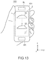
- FIG. 13 is a diagram showing how a moving object is displayed on a screen of a display of the information processing apparatus shown in FIG. 1 .
- FIG. 14 is a diagram showing examples of an L side vibration waveform and an R side vibration waveform according to the movement of a displayed object.
- FIG. 15 is a diagram showing an information processing apparatus in which two vibration devices are further added.
- FIG. 16 is a front view showing a mounting state of a stereo vibration belt to which the present technology is applied.
- FIG. 17 is a top view of a stereo vibration belt mounted on the waist of a user.
- FIG. 18 is a developed view of a stereo vibration belt when the stereo vibration belt is not mounted.
- FIG. 19 is a block diagram showing the configuration of a controller in a stereo vibration belt.
- FIG. 20 is a front view showing that right and left vibration devices in a stereo vibration belt are vibrated in a vertical direction.
- FIG. 21 is a front view showing that the up and down directions of vibrations of the right and left vibration devices in the stereo vibration belt shown in FIG. 20 are opposite to each other.
- FIG. 22 is a top view showing that right and left vibration devices in a stereo vibration belt are vibrated in a front-back horizontal direction.
- FIG. 23 is a top view showing that the front and back directions of vibrations of the right and left vibration devices in the stereo vibration belt shown in FIG. 22 are opposite to each other.
- FIG. 24 is a top view showing that the front and back directions of vibrations of the right and left vibration devices in the stereo vibration belt shown in FIG. 22 are the same.
- FIG. 25 is a front view showing that right and left vibration devices in a stereo vibration belt are vibrated in a belt body thickness direction.
- FIG. 26 is a front view showing that directions of vibrations of the right and left vibration devices in the stereo vibration belt shown in FIG. 25 in the belt body thickness direction are the same.
- FIG. 27 is a front view showing a stereo vibration device system to which the present technology is applied.
- FIG. 28 is a block diagram showing the electrical configuration of the stereo vibration device system.
- FIG. 29 is a top view showing a modification example of the stereo vibration belt.
- FIG. 30 is a perspective view showing a stereo vibration belt that can be mounted on the hand of a user.
- the present technology is applied to an information processing apparatus, such as a portable type mobile apparatus (for example, a smartphone) or a wearable type mobile apparatus.
- a portable type mobile apparatus for example, a smartphone
- a wearable type mobile apparatus for example, a wearable type mobile apparatus.
- FIG. 1 is a block diagram showing the hardware configuration of an information processing apparatus according to a first embodiment of the present technology.
- this information processing apparatus 100 includes an arithmetic processing unit 1 , a display 2 , an acceleration sensor 3 , a gyro sensor 4 , a sound output amplifier 5 , an L (left) side speaker 6 L (sound output device), an R (right) side speaker 6 R (sound output device), an L-side-vibration-device driving circuit 7 L, an R-side-vibration-device driving circuit 7 R, an L side vibration device 8 L (haptic-feedback presentation device), an R side vibration device 8 R (haptic-feedback presentation device), and the like.
- the arithmetic processing unit 1 is configured to include a central processing unit (CPU), a random access memory (RAM), a read only memory (ROM), a flash ROM, and the like.
- the CPU executes arithmetic processing for executing an operating system and an application program loaded into the main memory region of the RAM from the ROM and the flash ROM.
- the CPU performs display control of the display 2 connected to the arithmetic processing unit 1 , processing on a video captured by a camera unit (not shown), processing on acceleration data generated by the acceleration sensor 3 , processing on proximity data generated by a proximity sensor (not shown), processing on angular acceleration data generated by the gyro sensor 4 , and the like.
- the CPU controls the L-side-vibration-device driving circuit 7 L and the R-side-vibration-device driving circuit 7 R so that the L side vibration device 8 L and the R side vibration device 8 R vibrate with target vibration waveforms.
- the display 2 has a panel type display unit that displays an image and a display driving circuit that generates a signal to be output to the display unit on the basis of display data supplied from the arithmetic processing unit 1 .
- a touch sensor panel that generates a coordinate signal touched by the user and supplies the coordinate signal to the arithmetic processing unit 1 may be provided in the display unit of the display 2 .
- the acceleration sensor 3 is a sensor that detects the acceleration in three axial directions (xyz axis directions) applied to the information processing apparatus 100 .
- Biaxial directions of horizontal and vertical directions on the screen of the display 2 of the information processing apparatus 100 are assumed to be the x axis direction and the y axis direction, and a direction perpendicular to the x axis direction and the y axis direction is assumed to be the z axis direction.
- the gyro sensor 4 is a sensor that detects the angular acceleration around each of the three axes (xyz axes) given to the information processing apparatus 100 .
- Angular acceleration data detected by the gyro sensor 4 is used in processing of the arithmetic processing unit 1 , for example, in detection of the posture of the information processing apparatus 100 or shake correction.
- the sound output amplifier 5 generates a signal for driving the L side speaker 6 L from the L side sound data supplied from the arithmetic processing unit 1 and also generates a signal for driving the R side speaker 6 R from the R side sound data supplied from the arithmetic processing unit 1 .
- the L side vibration device 8 L and the R side vibration device 8 R are devices that generate vibration in the information processing apparatus 100 .
- a vibration device having a structure capable of generating an arbitrary vibration waveform with high degree of freedom by varying vibration time, vibration frequency, vibration amplitude, and the like is used.
- a vibration device such as a linear vibrator or a piezoelement is used.
- the L-side-vibration-device driving circuit 7 L supplies a driving signal to the L side vibration device 8 L on the basis of the L side vibration data supplied from the arithmetic processing unit 1 .
- the R-side-vibration-device driving circuit 7 R supplies a driving signal to the R side vibration device 8 R on the basis of the R side vibration data supplied from the arithmetic processing unit 1 .
- the arithmetic processing unit 1 is configured to generate a vibration waveform of each of the L side vibration device 8 L and the R side vibration device 8 R from the output stereo sound signal. A method of generating the vibration waveform of each of the vibration devices 8 L and 8 R will be described later.
- FIG. 2 is a diagram showing an example of an arrangement and vibration direction of the L side vibration device 8 L and the R side vibration device 8 R in a case where the information processing apparatus 100 according to the present technology is configured as a smartphone.
- the longer direction is assumed to be the x direction and the shorter direction is assumed to be the y direction.
- the L side vibration device 8 L and the R side vibration device 8 R are disposed in both end portions of a housing 101 of the information processing apparatus 100 in the x direction.
- the vibration direction of the L side vibration device 8 L and the R side vibration device 8 R is the y direction. Accordingly, the L side vibration device 8 L and the R side vibration device 8 R can be disposed as far as possible from the center of gravity G of the information processing apparatus 100 , and the vibration direction of the L side vibration device 8 L and the R side vibration device 8 R is a direction perpendicular to a straight line connecting the positions of the L side vibration device 8 L and the R side vibration device 8 R and the center of gravity G. Therefore, since a moment of force is generated by the vibration of the L side vibration device 8 L and the R side vibration device 8 R, vibration of larger energy can be generated.
- vibration in a direction approximately along the direction of gravity is transmitted to the user's hands.
- vibration can be given to the user with higher sensitivity.
- the vibration direction of the L side vibration device 8 L and the R side vibration device 8 R is a direction (y direction) perpendicular to the straight line connecting the positions of the L side vibration device 8 L and the R side vibration device 8 R and the center of gravity G in FIG. 2
- the L side vibration device 8 L and the R side vibration device 8 R may be vibrated in a direction including at least a component in the y direction.
- the L side vibration device 8 L and the R side vibration device 8 R may be vibrated in the x direction. Therefore, it is possible to give the user a feeling that the housing 101 of the information processing apparatus 100 expands and contracts in the x direction.
- the L side vibration device 8 L and the R side vibration device 8 R may be vibrated in the z axis direction.
- the L side vibration device 8 L and the R side vibration device 8 R may be disposed in both end portions of the housing 101 of the information processing apparatus 100 in the y direction.
- the L side vibration device 8 L and the R side vibration device 8 R may be configured by a plurality of vibration devices.
- the human audible range is approximately 20 Hz to 20000 Hz, and the frequency characteristic of the digital audio signal is also set according to this.
- low bands in particular, low frequencies of 100 Hz or lower, are said to be difficult to perceive as sound through human eardrum vibration.
- speakers there is a limit to the reproducibility of low frequency sound of 100 Hz or lower.
- Patent Literature 1 there is known a technology of replacing the woofer (bass) component of 5.1 ch audio with the vibration of a vibration device (refer to Patent Literature 1).
- vibration of only 1 ch is generated.
- the vibration of 1 ch there is a limit to the extensibility in the case of expressing information by vibration.
- the arithmetic processing unit 1 generates an L side vibration waveform and an R side vibration waveform from stereo sound signals, which are to be output to the L side speaker 6 L and the R side speaker 6 R, separately for the L and R sides as follows.
- FIG. 4 is a waveform diagram showing processing until vibration waveforms on the R and L sides are generated from stereo sound signals.
- the arithmetic processing unit 1 extracts a predetermined low frequency component signal from signals of stereo sound (sound of a plurality of channels) reproduced from, for example, a file stored in a memory or streaming received information. More specifically, the arithmetic processing unit 1 extracts a low frequency component signal of, for example, 100 Hz or lower (first low frequency component signal belonging to a frequency band of a predetermined frequency or lower: first characteristic information) from the L side sound signal (first sound signal corresponding to a first channel), and extracts a low frequency component signal of, for example, 100 Hz or lower (second low frequency component signal belonging to a frequency band of a predetermined frequency or lower: second characteristic information) from the R side sound signal (second sound signal corresponding to a second channel).
- the reproduced stereo sound signal is amplified by the sound output amplifier 5 and output to the L side speaker 6 L and the R side speaker 6 R.
- the arithmetic processing unit 1 normalizes the low frequency component signal extracted from the L side sound signal so as to have a level or a waveform suitable for driving the vibration device. Similarly, the low frequency component signal extracted from the R side sound signal is similarly normalized.
- the L side vibration waveform and the R side vibration waveform are generated.
- Data (first haptic-feedback presentation signal) of the generated L side vibration waveform is supplied to the L-side-vibration-device driving circuit 7 L, and the L side vibration device 8 L is driven.
- data (second haptic-feedback presentation signal) of the generated R side vibration waveform is supplied to the R-side-vibration-device driving circuit 7 R, and the R side vibration device 8 R is driven.
- the L side vibration device 8 L vibrates in synchronization with the low frequency component signal of the L side sound and the R side vibration device 8 R vibrates in synchronization with the low frequency component signal of the R side sound, stereo vibration synchronized with stereo sound is realized.
- the low frequency component of the stereo sound is output as both sound and vibration, a sufficient stereo feeling can be given to the user.
- vibration 31 of the R side vibration device 8 R attenuates and is transmitted as vibration noise to the user's left hand 41
- vibration 33 of the L side vibration device 8 L attenuates and is transmitted as vibration noise 34 to the user's right hand.
- FIG. 6 is a diagram showing the configuration of a portion, which generates vibration waveforms capable of canceling the above-described vibration noises 32 and 34 , in the arithmetic processing unit 1 .
- the arithmetic processing unit 1 generates a waveform having an opposite phase to the R side vibration waveform generated from the low frequency component of the R side sound of the stereo sound. Then, the arithmetic processing unit 1 adjusts the amplitude of the waveform having an opposite phase so as to match the value of vibration amplitude transmitted with attenuation from the R side vibration device 8 R to the L side end portion of the housing 101 of the information processing apparatus 100 (that is, amplitude of vibration transmitted with attenuation from the R side vibration device 8 R to the L side vibration device 8 L).
- a waveform for noise cancellation that has an opposite phase to the vibration noise 32 and an amplitude approximately equal to the vibration noise 32 (first opposite phase signal: a signal having an opposite phase to the low frequency component signal of the R side sound and a signal in which the amplitude of vibration output from the R side vibration device 8 R on the basis of the low frequency component signal of the R side sound corresponds to the amplitude of vibration attenuated along with transmission to the L side vibration device 8 L) is obtained.
- the arithmetic processing unit 1 adds the waveform for noise cancellation to the L side vibration waveform generated from the low frequency component of the L side sound of the stereo sound, and sets the result as the vibration waveform of the L side vibration device 8 L.
- the arithmetic processing unit 1 generates a waveform having an opposite phase to the L side vibration waveform generated from the low frequency component of the L side sound of the stereo sound. Then, the arithmetic processing unit 1 adjusts the amplitude of the waveform having an opposite phase so as to match the value of vibration amplitude transmitted with attenuation from the L side vibration device 8 L to the R side end portion of the housing 101 of the information processing apparatus 100 (that is, amplitude of vibration transmitted with attenuation from the L side vibration device 8 L to the R side vibration device 8 R).
- a waveform for noise cancellation that has an opposite phase to the vibration noise 34 and an amplitude approximately equal to the vibration noise 34 (second opposite phase signal: a signal having an opposite phase to the low frequency component signal of the L side sound and a signal in which the amplitude of vibration output from the L side vibration device 8 L on the basis of the low frequency component signal of the L side sound corresponds to the amplitude of vibration attenuated along with transmission to the R side vibration device 8 R) is obtained.
- the arithmetic processing unit 1 adds the waveform for noise cancellation to the R side vibration waveform generated from the low frequency component of the R side sound of the stereo sound, and sets the result as the vibration waveform of the R side vibration device 8 R.
- the vibration noise 32 transmitted to the left end portion of the housing 101 by the vibration 31 of the R side vibration device 8 R is cancelled out by the waveform component for noise cancellation superimposed on the vibration waveform of the L side vibration device 8 L.
- the vibration noise 34 transmitted to the right end portion of the housing 101 by the vibration 33 of the L side vibration device 8 L is cancelled out by the waveform component for noise cancellation superimposed on the vibration waveform of the R side vibration device 8 R.
- the arithmetic processing unit 1 of the information processing apparatus 100 is configured to determine whether a direction in the positional relationship between the two vibration devices 8 L and 8 R depending on the direction of the housing 101 of the information processing apparatus 100 is close to either the direction of gravity or the horizontal direction and to switch the method of generating vibration waveforms on the L and R sides between a case where it is determined that the direction in the positional relationship between the two vibration devices 8 L and 8 R is close to the horizontal direction and a case where it is determined that the direction in the positional relationship between the two vibration devices 8 L and 8 R is close to the direction of gravity.
- FIG. 8 is a flowchart showing a method of generating vibration waveforms on the L and R sides corresponding to the direction of the housing 101 of the information processing apparatus 100 .
- the arithmetic processing unit 1 determines the posture of the information processing apparatus 100 on the basis of the output of the gyro sensor 4 (step S 102 ). More specifically, for example, as shown in FIG. 7 , in a case where the information processing apparatus 100 is held with one hand, the x direction of the information processing apparatus 100 is a direction approximately along the direction of gravity. In this case, therefore, the arithmetic processing unit 1 determines that the housing 101 of the information processing apparatus 100 is in the vertical posture. Conversely, as shown in FIG. 3 , in a case where the information processing apparatus 100 is held with both hands, the y direction of the information processing apparatus 100 is a direction approximately along the direction of gravity. In this case, therefore, the arithmetic processing unit 1 determines that the housing 101 of the information processing apparatus 100 is in the horizontal posture.
- the arithmetic processing unit 1 extracts a predetermined low frequency component from each of the L side sound signal and the R side sound signal reproduced in step S 101 (step S 103 ). Then, the arithmetic processing unit 1 normalizes the extracted L side sound signal and R side sound signal so as to have a level or a waveform suitable for driving the vibration devices 8 L and 8 R (step S 104 ).
- the arithmetic processing unit 1 adds a waveform for noise cancellation to each of the normalized L side waveform and R side waveform (step S 105 ).
- the arithmetic processing unit 1 applies the L side waveform and the R side waveform after addition waveform to the corresponding vibration device driving circuits 7 L and 7 R, respectively (step S 106 ).
- the arithmetic processing unit 1 generates a monaural sound signal from the stereo sound signal (step S 107 ).
- the monaural sound signal is obtained by mixing the L side sound signal and the R side sound signal, for example.
- a monaural sound signal may be generated from one of the L side sound signal and the R side sound signal. Note that, FIG. 8 shows a case where a monaural sound signal is generated from the L side sound signal.
- the arithmetic processing unit 1 extracts a predetermined low frequency component (third low frequency component signal belonging to a frequency band of a predetermined frequency (for example, 100 Hz) or lower: third characteristic information) from the generated monaural sound signal (step S 108 ). Then, the arithmetic processing unit 1 normalizes the extracted monaural low frequency signal so as to have a level or a waveform suitable for driving the vibration devices 8 L and 8 R (step S 109 ).
- a predetermined low frequency component third low frequency component signal belonging to a frequency band of a predetermined frequency (for example, 100 Hz) or lower: third characteristic information) from the generated monaural sound signal.
- the arithmetic processing unit 1 normalizes the extracted monaural low frequency signal so as to have a level or a waveform suitable for driving the vibration devices 8 L and 8 R (step S 109 ).
- the arithmetic processing unit 1 generates a waveform having an opposite phase to the normalized waveform (step S 110 ), and applies the vibration waveforms having opposite phases to the L-side-vibration-device driving circuit 7 L and the R-side-vibration-device driving circuit 7 R, respectively (step S 111 ).
- the L side vibration device 8 L and the R side vibration device 8 R vibrate with vibration waveforms having opposite phases, for example, as shown in FIG. 9 , rightward acceleration is applied to the lower portion of the housing 101 of the information processing apparatus 100 when leftward acceleration is applied to the upper portion of the housing 101 of the information processing apparatus 100 , and conversely leftward acceleration is applied to the lower portion of the housing 101 of the information processing apparatus 100 when rightward acceleration is applied to the upper portion of the housing 101 of the information processing apparatus 100 . Therefore, compared with a case where the L side vibration device 8 L and the R side vibration device 8 R vibrate in the same phase, a large sense of vibration can be given to the user's hand holding the information processing apparatus 100 .
- the technology of vibrating the L side vibration device 8 L and the R side vibration device 8 R in opposite phases to give a strong sense of vibration to the user's hand can also be applied to a case where notification of some information is provided to the user through the vibration of the information processing apparatus 100 .
- the technology can be used for telephone, e-mail, and SNS message arrival, alarm notification of a schedule, and other notifications of information from various applications to the user.
- FIG. 10 is a flowchart showing a procedure of generating a vibration waveform by vibration notification.
- the arithmetic processing unit 1 When the conditions for starting the vibration notification are satisfied, for example, at the time of arrival of an incoming call (step S 201 ), the arithmetic processing unit 1 generates a waveform having an opposite phase to the waveform assigned to the notification information (step S 202 ), and applies one of the waveforms and the other waveform having an opposite phase to the corresponding vibration device driving circuits 7 L and 7 R as the vibration waveform of the L side vibration device 8 L and the vibration waveform of the R side vibration device 8 R, respectively (step S 203 ). As a result, the L side vibration device 8 L and the R side vibration device 8 R vibrate in opposite phases.
- the L side vibration device 8 L and the R side vibration device 8 R are vibrated in the y direction herein, the L side vibration device 8 L and the R side vibration device 8 R may be vibrated in a direction including at least a component in the y direction. Alternatively, the L side vibration device 8 L and the R side vibration device 8 R may be vibrated in the x direction. Therefore, it is possible to give the user a feeling that the housing 101 of the information processing apparatus 100 expands and contracts in the x direction. Furthermore, the vibration devices 8 L and 8 R may be vibrated in the z axis direction.
- the arithmetic processing unit 1 of the information processing apparatus 100 is configured to vibrate the L side vibration device and the R side vibration device with waveforms having the same phase as shown in FIG. 12 .
- This makes it possible to approximately equalize the intensity of vibration responding to the user depending on the touching position on the touch sensor panel. Therefore, an uncomfortable feeling due to variations in the intensity of response vibration at the time of operating the touch sensor panel is no longer given to the user.
- the vibration direction of each vibration device may be any of the x direction, the y direction, and the z axis direction.
- the vibrations of the L side vibration device 8 L and the R side vibration device 8 R may be controlled such that the direction of the movement of an object is felt in the user's hand in accordance with the direction of the movement of the object.
- the arithmetic processing unit 1 vibrates the L side vibration device 8 L and the R side vibration device 8 R with a time difference therebetween in this order with the L side vibration device 8 L on the upper side and the R side vibration device 8 R on the lower side. Therefore, the user can perceive vibration synchronized with the movement of the object 50 from the top to the bottom.
- FIG. 14 is a diagram showing examples of an L side vibration waveform and an R side vibration waveform according to the movement of a displayed object.
- a continuous feeling of movement of the object can be expressed by gradually increasing the intensity of the vibration of each of the vibration devices 8 L and 8 R and gradually decreasing the intensity of the vibration of each of the vibration devices 8 L and 8 R before the vibration is stopped.
- the R side vibration device 8 R and the L side vibration device 8 L may be vibrated with a time difference therebetween in this order.
- vibration devices 8 R′ and 8 L′ can be added to both end portions of the housing 101 of the information processing apparatus 100 in the y direction, so that the user can perceive vibration synchronized with the right and left movement of the object 50 in a case where the object 50 moves right and left on the screen of the display 2 in FIG. 13 .
- the vibration direction of each of the vibration devices 8 R′ and 8 L′ is the x direction.
- the stereo vibration technology described above can be applied not only to smartphones but also to game controllers. Further, without being limited to hand-held type information processing apparatuses such as smartphones and game controllers, the stereo vibration technology described above can also be applied to wearable devices that can be mounted on various mounting portions where a haptic feedback can be obtained, such as a wristband type wearable device mounted on the user's wrist, a neck type wearable device, and a head mounted display.
- processing for stereo vibration by the arithmetic processing unit 1 of the information processing apparatus 100 described above can be performed by a control unit of a cloud server (information processing apparatus) on a network.
- the arithmetic processing unit 1 of the information processing apparatus 100 described above sends a request to the control unit of the cloud server (information processing apparatus).
- the control unit of the cloud server (information processing apparatus) generates vibration waveforms of the vibration devices 8 L and 8 R of the information processing apparatus 100 on the basis of the low frequency component signal of the stereo sound to be output to the information processing apparatus 100 , and transmits the vibration waveforms to the information processing apparatus 100 through the network.
- FIG. 16 is a front view showing a state in which a stereo vibration belt 200 is mounted on the waist of a user U.
- FIG. 17 is a top view of the stereo vibration belt 200 mounted on the waist of the user U.
- FIG. 18 is a developed view of the stereo vibration belt 200 when the stereo vibration belt 200 is not mounted.
- the stereo vibration belt 200 includes a belt body 202 having one end to which a buckle unit 201 is fixed, an L side vibration device unit 203 L in which a vibration device is built, and an R side vibration device unit 203 R in which a vibration device is built. Note that, in these diagrams, right and left are right and left seen from the user U.
- the L side vibration device unit 203 L and the R side vibration device unit 203 R are disposed so as to be bilaterally symmetrical as seen from the user U when the stereo vibration belt 200 is mounted on the waist of the user U.
- the L side vibration device unit 203 L and the R side vibration device unit 203 R are provided on the left side (first side) and the right side (second side) opposite to the left side when the belt 200 is mounted on the user.
- a plurality of vibration devices 203 L and 203 R may be provided on the front side and the back side of the user (typically, the plurality of vibration devices 203 L and 203 R may be provided at any position as long as the plurality of vibration device units 203 L and 203 R are provided at opposite positions).
- the L side vibration device unit 203 L and the R side vibration device unit 203 R are slidable in predetermined slide regions SL and SR in the longitudinal direction of the belt body 202 so as to be able to be locked at slide positions determined by the user U. Further, it is desirable that marks indicating right and left are written on the surfaces of the outer cases of the L side vibration device unit 203 L and the R side vibration device unit 203 R so that the user U does not misunderstand the mounting direction of the stereo vibration belt 200 .
- a controller 211 is built into the buckle unit 201 .
- FIG. 19 is a block diagram showing the configuration of the controller 211 .
- the controller 211 has an arithmetic processing unit 212 , a wireless module 213 , an L-side-vibration-device driving circuit 214 L, an R-side-vibration-device driving circuit 214 R, a power supply unit (not shown), and the like.
- the arithmetic processing unit 212 is configured to include a CPU, a RAM, a ROM, a flash ROM, and the like.
- the CPU executes arithmetic processing for executing a program loaded into the main memory region of the RAM from the ROM and the flash ROM.
- the CPU controls the wireless module 213 , or controls the L-side-vibration-device driving circuit 214 L and the R-side-vibration-device driving circuit 214 R so that the vibration device in the L side vibration device unit 203 L mounted on the belt body 202 and the vibration device in the R side vibration device unit 203 R mounted on the belt body 202 vibrate with target vibration waveforms.
- the output of the L-side-vibration-device driving circuit 214 L is supplied to the L side vibration device unit 203 L through a signal wiring line 215 L provided in the belt body 202 so that the vibration device in the L side vibration device unit 203 L is driven, and the output of the R-side-vibration-device driving circuit 214 R is supplied to the R side vibration device unit 203 R through a signal wiring line 215 R provided in the belt body 202 so that the vibration device in the R side vibration device unit 203 R is driven.
- the wireless module 213 receives a stereo sound signal wirelessly transmitted from an information processing apparatus 300 , such as a portable type mobile apparatus (for example, a smartphone) or a wearable type mobile apparatus.
- the wireless module 213 is a wireless module for short-range wireless communication, such as Bluetooth (registered trademark), for example.
- data of the vibration waveforms on the L and R sides generated from the stereo sound signal in the arithmetic processing unit of the information processing apparatus 300 may be transmitted from the information processing apparatus 300 to the controller 211 of the stereo vibration belt 200 .
- the power supply unit (not shown) is configured by a DC/DC converter or the like that generates electric power necessary for the operation of the stereo vibration belt 200 from charges of a primary battery or a secondary battery, for example.
- the information processing apparatus 300 wirelessly transmits stereo sound signals, which are to be output to an L side speaker and an R side speaker, to the controller 211 of the stereo vibration belt 200 .
- the arithmetic processing unit 212 extracts a low frequency component signal of, for example, 100 Hz or lower, from the stereo sound signal wirelessly received from the information processing apparatus 300 , generates an L side vibration waveform and an R side vibration waveform by normalizing the low frequency component signal so as to have a level or a waveform suitable for driving the vibration device in the L side vibration device unit 203 L and the vibration device in the R side vibration device unit 203 R, and supplies the L side vibration waveform and the R side vibration waveform to the L-side-vibration-device driving circuit 214 L and the R-side-vibration-device driving circuit 214 R.
- the vibration device in the L side vibration device unit 203 L vibrates in synchronization with the low frequency component signal of the L side sound
- the vibration device in the R side vibration device unit 203 R vibrates in synchronization with the low frequency component signal of the R side sound.
- the user U can taste the stereo vibration synchronized with the stereo sound throughout the body through the waist.
- FIG. 20 shows an example in which the vibration device in the L side vibration device unit 203 L and the vibration device in the R side vibration device unit 203 R are vibrated in the short side direction of the belt body 202 so that vibration in the vertical direction is given to the user U.
- the arithmetic processing unit 212 may drive the vibration device in the L side vibration device unit 203 L and the vibration device in the R side vibration device unit 203 R with vibration waveforms having opposite phases generated from the sound signal obtained by making the stereo sound signal monaural, so that the up and down directions of the vibrations on the L and R sides are opposite to each other. In this manner, it is possible to give the user U a larger sense of vibration.
- FIG. 22 shows an example in which the vibration device in the L side vibration device unit 203 L and the vibration device in the R side vibration device unit 203 R are vibrated in the longitudinal direction of the belt body 202 so that vibration in the horizontal direction is given to the user U.
- the arithmetic processing unit 212 may drive the vibration device in the L side vibration device unit 203 L and the vibration device in the R side vibration device unit 203 R with vibration waveforms having opposite phases generated from the sound signal obtained by making the stereo sound signal monaural, so that the front and back directions of the vibrations are opposite to each other. In this manner, it is possible to give the user U a sense of force in the horizontal rotation direction. Further, as shown in FIG.
- the arithmetic processing unit 212 may generate vibration waveforms having the same phase from the sound signal obtained by making the stereo sound signal monaural and drive the vibration device in the L side vibration device unit 203 L and the vibration device in the R side vibration device unit 203 R, so that the front and back directions of the vibrations are the same. In this case, it is possible to mainly give the user U a sense of force in the front-back direction.
- FIG. 25 shows an example in which the vibration device in the L side vibration device unit 203 L and the vibration device in the R side vibration device unit 203 R are vibrated in the thickness direction of the belt body 202 so that vibration is given to the waist of the user U so as to repeat compression and release.
- the arithmetic processing unit 212 may drive the vibration device in the L side vibration device unit 203 L and the vibration device in the R side vibration device unit 203 R with vibration waveforms having the same phase generated from the sound signal obtained by making the stereo sound signal monaural, so that the direction of each vibration in the belt body thickness direction is always the same.
- FIG. 27 is a diagram showing a stereo vibration device system 400 including an L side vibration device unit 404 L and an R side vibration device unit 404 R that can be separately attached to and detached from a general belt 402 .
- the L side vibration device unit 404 L and the R side vibration device unit 404 R have mounting portions 405 , such as hooks, so that these can be separately mounted on arbitrary positions of the general belt 402 .
- FIG. 28 is a block diagram showing the electrical configuration of the stereo vibration device system 400 .
- the L side vibration device unit 404 L has an arithmetic processing unit 412 L, a wireless module 413 L, an L-side-vibration-device driving circuit 414 L, an L side vibration device 416 L, a power supply unit (not shown), and the like.
- the arithmetic processing unit 412 L is configured to include a CPU, a RAM, a ROM, a flash ROM, and the like.
- the CPU executes arithmetic processing for executing a program loaded into the main memory region of the RAM from the ROM and the flash ROM.
- the CPU controls the wireless module 413 L, or controls the L-side-vibration-device driving circuit 414 L to vibrate the L side vibration device 416 L with a target vibration waveform.
- the output of the L-side-vibration-device driving circuit 414 L is supplied to the L side vibration device 416 L in the L side vibration device unit 404 L, so that the L side vibration device 416 L is driven.
- the wireless module 413 L receives a stereo sound signal wirelessly transmitted from the information processing apparatus 300 , such as a portable type mobile apparatus (for example, a smartphone) or a wearable type mobile apparatus.
- the wireless module 413 L is a wireless module for short-range wireless communication, such as Bluetooth (registered trademark), for example.
- data of the vibration waveform on the L side generated from the stereo sound signal in the arithmetic processing unit of the information processing apparatus 300 may be transmitted from the information processing apparatus 300 to the L side vibration device unit 404 L.
- the power supply unit (not shown) is configured by a DC/DC converter or the like that generates electric power necessary for the operation of the L side vibration device unit 404 L from charges of a primary battery or a secondary battery, for example.
- the R side vibration device unit 404 R has an arithmetic processing unit 412 R, a wireless module 413 R, an R-side-vibration-device driving circuit 414 R, an R side vibration device 416 R, a power supply unit (not shown), and the like.
- the arithmetic processing unit 412 R is configured to include a CPU, a RAM, a ROM, a flash ROM, and the like.
- the CPU executes arithmetic processing for executing a program loaded into the main memory region of the RAM from the ROM and the flash ROM.
- the CPU controls the wireless module 413 R, or controls the R-side-vibration-device driving circuit 414 R to vibrate the R side vibration device 416 R with a target vibration waveform.
- the output of the R-side-vibration-device driving circuit 414 R is supplied to the R side vibration device 416 R in the R side vibration device unit 404 R, so that the R side vibration device 416 R is driven.
- the wireless module 413 R receives a stereo sound signal wirelessly transmitted from the information processing apparatus 300 , such as a portable type mobile apparatus (for example, a smartphone) or a wearable type mobile apparatus.
- the wireless module 413 R is a wireless module for short-range wireless communication, such as Bluetooth (registered trademark), for example.
- data of the vibration waveform on the R side generated from the stereo sound signal in the arithmetic processing unit of the information processing apparatus 300 may be transmitted from the information processing apparatus 300 to the R side vibration device unit 404 R.
- the power supply unit (not shown) is configured by a DC/DC converter or the like that generates electric power necessary for the operation of the R side vibration device unit 404 R from charges of a primary battery or a secondary battery, for example.
- the sound signal to be output to the L side speaker of the information processing apparatus 300 is wirelessly transmitted to the L side vibration device unit 404 L
- the sound signal to be output to the R side speaker of the information processing apparatus 300 is wirelessly transmitted to the R side vibration device unit 404 R.
- the arithmetic processing unit 412 L extracts a low frequency component signal of, for example, 100 Hz or lower, from the L side sound signal wirelessly received from the information processing apparatus 300 , generates an L side vibration waveform by normalizing the low frequency component signal so as to have a level or a waveform suitable for driving the vibration device 416 L, and supplies the L side vibration waveform to the L-side-vibration-device driving circuit 414 L.
- the L side vibration device 416 L vibrates in synchronization with the low frequency component signal of the L side sound.
- the arithmetic processing unit 412 R extracts a low frequency component signal of, for example, 100 Hz or lower, from the R side sound signal wirelessly received from the information processing apparatus 300 , generates an R side vibration waveform by normalizing the low frequency component signal so as to have a level or a waveform suitable for driving the vibration device 416 R, and supplies the R side vibration waveform to the R-side-vibration-device driving circuit 414 R. Therefore, the R side vibration device 416 R vibrates in synchronization with the low frequency component signal of the R side sound.
- the user U can taste the stereo vibration by the L side vibration device unit 404 L and the R side vibration device unit 404 R throughout the body through the waist.
- the positions of the L side vibration device unit 404 L and the R side vibration device unit 404 R can be freely selected.
- the L side vibration device unit 404 L and the R side vibration device unit 404 R In order to taste a clear stereo feeling, it is important for the L side vibration device unit 404 L and the R side vibration device unit 404 R to be correctly mounted at the bilaterally symmetrical positions of the waist of the user U with the relationship of right and left.
- the stereo vibration device system 400 since the L side vibration device unit 404 L and the R side vibration device unit 404 R are separately provided, there is a possibility that the L side vibration device unit 404 L and the R side vibration device unit 404 R will be reversely mounted on a belt 202 a . In order to prevent such a mounting error, it is desirable that marks or the like indicating right and left are written on the outer cases of the L side vibration device unit 404 L and the R side vibration device unit 404 R by printing or the like.
- the L side vibration device unit 203 L and the R side vibration device unit 203 R are configured to be slidable in predetermined slide regions ST and SR in the longitudinal direction of the belt body 202 , so that it is possible to cope with a difference in waist size between users.
- FIG. 29 is a diagram showing a stereo vibration belt 200 a for which adjustment of the positions of the L side vibration device unit 203 L and the R side vibration device unit 203 R for each user can be omitted.
- a belt body 202 c is used in which expandable portions 202 b , which can expand and contract in the longitudinal direction, are symmetrically provided in the front and rear and the right and left.
- the bilaterally symmetrical positional relationship between the L side vibration device unit 203 L and the R side vibration device unit 203 is not disturbed by the difference in the size of the circumference of the waist between the users U 1 and U 2 .
- the stereo vibration belt 200 a is shared by the plurality of users U 1 and U 2 , it is not necessary to adjust the positions the L side vibration device unit 203 L and the R side vibration device unit 203 .
- the entire belt body 202 c may be configured by the expandable portions 202 b.
- stereo vibration belt that can be wrapped around the waist of the user has been described so far, a stereo vibration belt 200 b wrapped around the wrist of the user as shown in FIG. 30 can be used. Furthermore, a stereo vibration belt that can be wrapped around the neck, ankle, or the like of the user can be used.
- the vibration device units 203 L and 203 R may be provided in wearable devices other than the belt type.
- the vibration device units 203 L and 203 R may be provided in various wearable devices, such as a head mounted display and a glasses type wearable device.
- the speakers 6 L and 6 R have been described as examples of the sound output device.
- the sound output device may be a headphone (including an earphone).
- the sound output device is not limited to a sound output device corresponding to a sound signal of two channels (that is, a stereo signal), and may be a sound output device corresponding to a sound signal of three or more channels (for example, a multi-channel speaker of three or more channels).
- the sound signal as a basis for vibrating the haptic-feedback presentation devices is a stereo signal (that is, two channels)
- the sound signal may be a sound signal of three or more channels.
- the number of sound output devices may be three or more (for example, a case where sound signals are three or more channels).
- the vibration devices 8 L and 8 R and the vibration device units 203 L and 203 R have been taken as examples.
- the haptic-feedback presentation device may be a device that presents a haptic feedback to the user by pressure.
- the number of haptic-feedback presentation devices may be three or more (for example, a case where sound signals are three or more channels).
- the haptic-feedback presentation signal supplied to the haptic-feedback presentation device is a signal having a vibration waveform
- the haptic-feedback presentation signal may be a signal having a waveform of pressure
- low frequency components (the first characteristic information and the second characteristic information) belonging to a frequency band of a predetermined frequency or lower are extracted from the sound signal and haptic-feedback presentation signals (the first haptic-feedback presentation signal and the second haptic-feedback presentation signal) are generated on the basis of the low frequency components.
- high frequency components belonging to a frequency band of a predetermined frequency or higher may be extracted from the sound signal, and haptic-feedback presentation signals (the first haptic-feedback presentation signal and the second haptic-feedback presentation signal) may be generated on the basis of the high frequency components (note that, this also applies to the third characteristic information in the monaural sound signal described above).
- the high frequency components are components in a frequency band that are difficult to perceive as sound through the eardrum by the user.
- the present technology can also adopt the following configuration.
- An information processing apparatus including: an arithmetic processing unit that generates a first haptic-feedback presentation signal, which is to be supplied to a first haptic-feedback presentation device of a plurality of haptic-feedback presentation devices, on the basis of first characteristic information extracted from a first sound signal corresponding to a first channel among sounds of a plurality of channels output from a sound output device capable of outputting the sounds of the plurality of channels and generates a second haptic-feedback presentation signal, which is to be supplied to a second haptic-feedback presentation device of the plurality of haptic-feedback presentation devices, on the basis of second characteristic information extracted from a second sound signal corresponding to a second channel among the sounds of the plurality of channels.
- the arithmetic processing unit in which, in a case where it is determined that the direction in the positional relationship is close to the direction of gravity, the arithmetic processing unit generates a monaural sound signal from sound signals of the plurality of channels and generates the first haptic-feedback presentation signal and the second haptic-feedback presentation signal on the basis of the monaural sound signal.
- An information processing method including: generating, by an arithmetic processing unit, a first haptic-feedback presentation signal, which is to be supplied to a first haptic-feedback presentation device of a plurality of haptic-feedback presentation devices, on the basis of first characteristic information extracted from a first sound signal corresponding to a first channel, among sounds of a plurality of channels output from a sound output device capable of outputting the sounds of the plurality of channels; and generating, by an arithmetic processing unit, a second haptic-feedback presentation signal, which is to be supplied to a second haptic-feedback presentation device of the plurality of haptic-feedback presentation devices, on the basis of second characteristic information extracted from a second sound signal corresponding to a second channel, among the sounds of the plurality of channels.
- a program causing a computer to function as: an arithmetic processing unit that generates a first haptic-feedback presentation signal, which is to be supplied to a first haptic-feedback presentation device of a plurality of haptic-feedback presentation devices, on the basis of first characteristic information extracted from a first sound signal corresponding to a first channel among sounds of a plurality of channels output from a sound output device capable of outputting the sounds of the plurality of channels and generates a second haptic-feedback presentation signal, which is to be supplied to a second haptic-feedback presentation device of the plurality of haptic-feedback presentation devices, on the basis of second characteristic information extracted from a second sound signal corresponding to a second channel among the sounds of the plurality of channels.
- An information processing apparatus including: a control unit that receives a request from an information processing terminal through a network, generates a first haptic-feedback presentation signal, which is to be supplied to a first haptic-feedback presentation device of a plurality of haptic-feedback presentation devices, on the basis of first characteristic information extracted from a first sound signal corresponding to a first channel among sounds of a plurality of channels output from a sound output device capable of outputting the sounds of the plurality of channels, generates a second haptic-feedback presentation signal, which is to be supplied to a second haptic-feedback presentation device of the plurality of haptic-feedback presentation devices, on the basis of second characteristic information extracted from a second sound signal corresponding to a second channel among the sounds of the plurality of channels, and transmits information of the first haptic-feedback presentation signal and the second haptic-feedback presentation signal to the information processing terminal through the network.
Abstract
Description
- 1 arithmetic processing unit
- 2 display
- 3 acceleration sensor
- 4 gyro sensor
- 5.L sound output amplifier
- 5 sound output amplifier
- 6L L side speaker
- 6R R side speaker
- 7L L-side-vibration-device driving circuit
- 7R R-side-vibration-device driving circuit
- 8L L side vibration device
- 8R R side vibration device
- 100 information processing apparatus
- 101 housing
Claims (12)
Applications Claiming Priority (7)
| Application Number | Priority Date | Filing Date | Title |
|---|---|---|---|
| JP2016-198777 | 2016-10-07 | ||
| JPJP2016-198777 | 2016-10-07 | ||
| JP2016198777 | 2016-10-07 | ||
| JP2017100764A JP6977312B2 (en) | 2016-10-07 | 2017-05-22 | Information processing equipment, information processing methods and programs |
| JP2017-100764 | 2017-05-22 | ||
| JPJP2017-100764 | 2017-05-22 | ||
| PCT/JP2017/032408 WO2018066299A1 (en) | 2016-10-07 | 2017-09-08 | Information processing device, information processing method, and program |
Publications (2)
| Publication Number | Publication Date |
|---|---|
| US20190220095A1 US20190220095A1 (en) | 2019-07-18 |
| US11009956B2 true US11009956B2 (en) | 2021-05-18 |
Family
ID=61966972
Family Applications (1)
| Application Number | Title | Priority Date | Filing Date |
|---|---|---|---|
| US16/328,913 Active US11009956B2 (en) | 2016-10-07 | 2017-09-08 | Information processing apparatus and information processing method for presentation of multiple haptic feedback channels based on sound characteristics extracted from multiple sound channels |
Country Status (2)
| Country | Link |
|---|---|
| US (1) | US11009956B2 (en) |
| JP (1) | JP6977312B2 (en) |
Cited By (2)
| Publication number | Priority date | Publication date | Assignee | Title |
|---|---|---|---|---|
| US11422624B2 (en) * | 2017-09-27 | 2022-08-23 | Contact Control Interfaces, LLC | Hand interface device utilizing haptic force gradient generation via the alignment of fingertip haptic units |
| US11710389B2 (en) | 2019-02-22 | 2023-07-25 | Ck Materials Lab Co., Ltd. | Haptic providing device and method for converting sound signal to haptic signal |
Families Citing this family (34)
| Publication number | Priority date | Publication date | Assignee | Title |
|---|---|---|---|---|
| US10732714B2 (en) | 2017-05-08 | 2020-08-04 | Cirrus Logic, Inc. | Integrated haptic system |
| US11259121B2 (en) | 2017-07-21 | 2022-02-22 | Cirrus Logic, Inc. | Surface speaker |
| US11051112B2 (en) * | 2018-01-09 | 2021-06-29 | Cirrus Logic, Inc. | Multiple audio transducers driving a display to establish localized quiet zones |
| US10832537B2 (en) * | 2018-04-04 | 2020-11-10 | Cirrus Logic, Inc. | Methods and apparatus for outputting a haptic signal to a haptic transducer |
| WO2019220495A1 (en) * | 2018-05-14 | 2019-11-21 | 株式会社ソニー・インタラクティブエンタテインメント | Information processing device |
| JPWO2019244716A1 (en) * | 2018-06-19 | 2021-06-24 | ソニーグループ株式会社 | Information processing equipment, information processing methods, and programs |
| US11269415B2 (en) | 2018-08-14 | 2022-03-08 | Cirrus Logic, Inc. | Haptic output systems |
| US20220050525A1 (en) * | 2018-09-18 | 2022-02-17 | Sony Corporation | Sensation induction device and sound output system |
| JP2020067701A (en) | 2018-10-22 | 2020-04-30 | ソニー株式会社 | Tactile sensation presentation device and tactile sensation presentation method |
| GB201817495D0 (en) | 2018-10-26 | 2018-12-12 | Cirrus Logic Int Semiconductor Ltd | A force sensing system and method |
| WO2020121662A1 (en) * | 2018-12-13 | 2020-06-18 | ソニー株式会社 | Information processing device, information processing system, information processing method, and program |
| US11644370B2 (en) | 2019-03-29 | 2023-05-09 | Cirrus Logic, Inc. | Force sensing with an electromagnetic load |
| US10992297B2 (en) | 2019-03-29 | 2021-04-27 | Cirrus Logic, Inc. | Device comprising force sensors |
| US20200313529A1 (en) | 2019-03-29 | 2020-10-01 | Cirrus Logic International Semiconductor Ltd. | Methods and systems for estimating transducer parameters |
| US10955955B2 (en) | 2019-03-29 | 2021-03-23 | Cirrus Logic, Inc. | Controller for use in a device comprising force sensors |
| US10726683B1 (en) | 2019-03-29 | 2020-07-28 | Cirrus Logic, Inc. | Identifying mechanical impedance of an electromagnetic load using a two-tone stimulus |
| US10828672B2 (en) | 2019-03-29 | 2020-11-10 | Cirrus Logic, Inc. | Driver circuitry |
| US11509292B2 (en) | 2019-03-29 | 2022-11-22 | Cirrus Logic, Inc. | Identifying mechanical impedance of an electromagnetic load using least-mean-squares filter |
| WO2020241170A1 (en) | 2019-05-28 | 2020-12-03 | ソニー株式会社 | Information processing device, information processing method, and program |
| US10976825B2 (en) | 2019-06-07 | 2021-04-13 | Cirrus Logic, Inc. | Methods and apparatuses for controlling operation of a vibrational output system and/or operation of an input sensor system |
| CN114008569A (en) | 2019-06-21 | 2022-02-01 | 思睿逻辑国际半导体有限公司 | Method and apparatus for configuring a plurality of virtual buttons on a device |
| CN114424149A (en) | 2019-09-25 | 2022-04-29 | 索尼集团公司 | Information processing apparatus, information processing method, server apparatus, and program |
| WO2021059423A1 (en) * | 2019-09-26 | 2021-04-01 | 日本電信電話株式会社 | Vibration presentation system |
| US11408787B2 (en) | 2019-10-15 | 2022-08-09 | Cirrus Logic, Inc. | Control methods for a force sensor system |
| US11380175B2 (en) | 2019-10-24 | 2022-07-05 | Cirrus Logic, Inc. | Reproducibility of haptic waveform |
| US11545951B2 (en) | 2019-12-06 | 2023-01-03 | Cirrus Logic, Inc. | Methods and systems for detecting and managing amplifier instability |
| DE112020006211T5 (en) * | 2019-12-19 | 2022-11-10 | Sony Group Corporation | Control device, signal processing method and loudspeaker device |
| JPWO2021131767A1 (en) * | 2019-12-25 | 2021-07-01 | ||
| US11662821B2 (en) | 2020-04-16 | 2023-05-30 | Cirrus Logic, Inc. | In-situ monitoring, calibration, and testing of a haptic actuator |
| US11933822B2 (en) | 2021-06-16 | 2024-03-19 | Cirrus Logic Inc. | Methods and systems for in-system estimation of actuator parameters |
| US11765499B2 (en) | 2021-06-22 | 2023-09-19 | Cirrus Logic Inc. | Methods and systems for managing mixed mode electromechanical actuator drive |
| US11908310B2 (en) | 2021-06-22 | 2024-02-20 | Cirrus Logic Inc. | Methods and systems for detecting and managing unexpected spectral content in an amplifier system |
| US11552649B1 (en) | 2021-12-03 | 2023-01-10 | Cirrus Logic, Inc. | Analog-to-digital converter-embedded fixed-phase variable gain amplifier stages for dual monitoring paths |
| US20240048929A1 (en) | 2022-08-05 | 2024-02-08 | Aac Microtech (Changzhou) Co., Ltd. | Method and system of sound processing for mobile terminal based on hand holding and orientation detection |
Citations (15)
| Publication number | Priority date | Publication date | Assignee | Title |
|---|---|---|---|---|
| JP2005258666A (en) | 2004-03-10 | 2005-09-22 | Sony Corp | Input device, electronic device, and method for inputting touch to electronic device as feedback |
| US20100160016A1 (en) * | 2006-03-31 | 2010-06-24 | Shimabukuro Jorge L | Portable Wagering Game With Vibrational Cues and Feedback Mechanism |
| US20110157052A1 (en) * | 2009-12-24 | 2011-06-30 | Samsung Electronics Co., Ltd. | Method and apparatus for generating vibrations in portable terminal |
| EP2487557A2 (en) | 2011-02-11 | 2012-08-15 | Immersion Corporation | Sound to haptic effect conversion system using amplitude value |
| US20120206247A1 (en) | 2011-02-11 | 2012-08-16 | Immersion Corporation | Sound to haptic effect conversion system using waveform |
| US20130022221A1 (en) * | 2011-07-19 | 2013-01-24 | Christopher Kallai | Shaping sound responsive to speaker orientation |
| EP2624099A1 (en) | 2012-02-03 | 2013-08-07 | Immersion Corporation | Sound to haptic effect conversion system using waveform |
| US20140253302A1 (en) * | 2013-03-11 | 2014-09-11 | Vincent Levesque | Systems And Methods For Haptics In Vibrating Environments And Devices |
| US20140348348A1 (en) * | 2010-09-01 | 2014-11-27 | Woojer Ltd | Personal media playing system |
| US20150070153A1 (en) * | 2013-09-06 | 2015-03-12 | Immersion Corporation | Spatialized haptic feedback based on dynamically scaled values |
| US20150077324A1 (en) * | 2013-09-18 | 2015-03-19 | Immersion Corporation | Orientation adjustable multi-channel haptc device |
| US20150209668A1 (en) * | 2014-01-30 | 2015-07-30 | Obana Kazutoshi | Information processing apparatus, storage medium having stored therein information processing program, information processing system, and information processing method |
| US20160116982A1 (en) * | 2014-10-28 | 2016-04-28 | Lg Electronics Inc. | Terminal and operating method thereof |
| WO2016092644A1 (en) | 2014-12-10 | 2016-06-16 | 富士通株式会社 | Electronic device and drive control method |
| US20170256144A1 (en) * | 2016-03-07 | 2017-09-07 | Immersion Corporation | Systems and Methods for Haptic Surface Elements |
Family Cites Families (3)
| Publication number | Priority date | Publication date | Assignee | Title |
|---|---|---|---|---|
| JP3771621B2 (en) * | 1996-02-20 | 2006-04-26 | 富士通コンポーネント株式会社 | Small computer |
| JP4345632B2 (en) * | 2004-10-01 | 2009-10-14 | 日本電気株式会社 | Mobile phone with panel speaker and communication method using mobile phone with panel speaker |
| JP5667018B2 (en) * | 2011-09-06 | 2015-02-12 | Kddi株式会社 | Mobile phone terminal, voice transmission method for mobile phone terminal, voice transmission program for mobile phone terminal |
-
2017
- 2017-05-22 JP JP2017100764A patent/JP6977312B2/en active Active
- 2017-09-08 US US16/328,913 patent/US11009956B2/en active Active
Patent Citations (28)
| Publication number | Priority date | Publication date | Assignee | Title |
|---|---|---|---|---|
| JP2005258666A (en) | 2004-03-10 | 2005-09-22 | Sony Corp | Input device, electronic device, and method for inputting touch to electronic device as feedback |
| US20100160016A1 (en) * | 2006-03-31 | 2010-06-24 | Shimabukuro Jorge L | Portable Wagering Game With Vibrational Cues and Feedback Mechanism |
| US20110157052A1 (en) * | 2009-12-24 | 2011-06-30 | Samsung Electronics Co., Ltd. | Method and apparatus for generating vibrations in portable terminal |
| US20140348348A1 (en) * | 2010-09-01 | 2014-11-27 | Woojer Ltd | Personal media playing system |
| CN102750957A (en) | 2011-02-11 | 2012-10-24 | 英默森公司 | Sound to haptic effect conversion system using waveform |
| US20120206247A1 (en) | 2011-02-11 | 2012-08-16 | Immersion Corporation | Sound to haptic effect conversion system using waveform |
| KR20120094849A (en) | 2011-02-11 | 2012-08-27 | 임머숀 코퍼레이션 | Sound to haptic effect conversion system using amplitude value |
| JP2012168947A (en) | 2011-02-11 | 2012-09-06 | Immersion Corp | Sound to haptic effect conversion system using amplitude value |
| US20150241975A1 (en) | 2011-02-11 | 2015-08-27 | Immersion Corporation | Sound to haptic effect conversion system using waveform |
| KR20130086590A (en) | 2011-02-11 | 2013-08-02 | 임머숀 코퍼레이션 | Sound to haptic effect conversion system using amplitude value |
| CN103247296A (en) | 2011-02-11 | 2013-08-14 | 英默森公司 | Sound to haptic effect conversion system using waveform |
| US20140152429A1 (en) | 2011-02-11 | 2014-06-05 | Immersion Corporation | Sound to haptic effect conversion system using waveform |
| US20120206246A1 (en) | 2011-02-11 | 2012-08-16 | Immersion Corporation | Sound to haptic effect conversion system using amplitude value |
| EP2487557A2 (en) | 2011-02-11 | 2012-08-15 | Immersion Corporation | Sound to haptic effect conversion system using amplitude value |
| US20170213430A1 (en) | 2011-02-11 | 2017-07-27 | Immersion Corporation | Sound to haptic effect conversion system using waveform |
| US20130022221A1 (en) * | 2011-07-19 | 2013-01-24 | Christopher Kallai | Shaping sound responsive to speaker orientation |
| EP2624099A1 (en) | 2012-02-03 | 2013-08-07 | Immersion Corporation | Sound to haptic effect conversion system using waveform |
| US20140253302A1 (en) * | 2013-03-11 | 2014-09-11 | Vincent Levesque | Systems And Methods For Haptics In Vibrating Environments And Devices |
| US20150070153A1 (en) * | 2013-09-06 | 2015-03-12 | Immersion Corporation | Spatialized haptic feedback based on dynamically scaled values |
| EP2851763A1 (en) | 2013-09-18 | 2015-03-25 | Immersion Corporation | Orientation adjustable multi-channel haptic device |
| CN104460983A (en) | 2013-09-18 | 2015-03-25 | 意美森公司 | Orientation adjustable multi-channel haptic device |
| KR20150032475A (en) | 2013-09-18 | 2015-03-26 | 임머숀 코퍼레이션 | Orientation adjustable multi-channel haptic device |
| JP2015060591A (en) | 2013-09-18 | 2015-03-30 | イマージョン コーポレーションImmersion Corporation | Orientation adjustable multi-channel haptic device |
| US20150077324A1 (en) * | 2013-09-18 | 2015-03-19 | Immersion Corporation | Orientation adjustable multi-channel haptc device |
| US20150209668A1 (en) * | 2014-01-30 | 2015-07-30 | Obana Kazutoshi | Information processing apparatus, storage medium having stored therein information processing program, information processing system, and information processing method |
| US20160116982A1 (en) * | 2014-10-28 | 2016-04-28 | Lg Electronics Inc. | Terminal and operating method thereof |
| WO2016092644A1 (en) | 2014-12-10 | 2016-06-16 | 富士通株式会社 | Electronic device and drive control method |
| US20170256144A1 (en) * | 2016-03-07 | 2017-09-07 | Immersion Corporation | Systems and Methods for Haptic Surface Elements |
Non-Patent Citations (1)
| Title |
|---|
| International Search Report and Written Opinion of PCT Application No. PCT/JP2017/032408, dated Oct. 17, 2017, 09 pages of ISRWO. |
Cited By (2)
| Publication number | Priority date | Publication date | Assignee | Title |
|---|---|---|---|---|
| US11422624B2 (en) * | 2017-09-27 | 2022-08-23 | Contact Control Interfaces, LLC | Hand interface device utilizing haptic force gradient generation via the alignment of fingertip haptic units |
| US11710389B2 (en) | 2019-02-22 | 2023-07-25 | Ck Materials Lab Co., Ltd. | Haptic providing device and method for converting sound signal to haptic signal |
Also Published As
| Publication number | Publication date |
|---|---|
| US20190220095A1 (en) | 2019-07-18 |
| JP6977312B2 (en) | 2021-12-08 |
| JP2018064264A (en) | 2018-04-19 |
Similar Documents
| Publication | Publication Date | Title |
|---|---|---|
| US11009956B2 (en) | Information processing apparatus and information processing method for presentation of multiple haptic feedback channels based on sound characteristics extracted from multiple sound channels | |
| EP2839675B1 (en) | Auto detection of headphone orientation | |
| CN107071648B (en) | Sound playing adjusting system, device and method | |
| US9577710B2 (en) | Engaging terminal devices | |
| JP6315434B2 (en) | Transmitter / receiver | |
| WO2019233325A1 (en) | Notification method and mobile terminal | |
| CN110764730A (en) | Method and device for playing audio data | |
| CN108008858B (en) | Terminal control method and mobile terminal | |
| US9532736B2 (en) | Portable electronic device with a tinnitus relief application | |
| CN112118527A (en) | Multimedia information processing method, device and storage medium | |
| CN107454531B (en) | Loudspeaker, terminal and volume adjusting method | |
| JP2015144430A (en) | Hearing device using position data, audio system and related method | |
| CN108683980B (en) | Audio signal transmission method and mobile terminal | |
| JP2016019160A (en) | Electronic apparatus, method and program | |
| KR102180496B1 (en) | Tactile bass response | |
| US11774991B2 (en) | Information processing apparatus, information processing method, and computer program product for controlling vibration | |
| CN108430004B (en) | Loudspeaker amplitude adjusting device, adjusting method and mobile terminal | |
| WO2018066299A1 (en) | Information processing device, information processing method, and program | |
| JP2018023601A (en) | Voice processing program, information processing program, voice processing method, voice processing device, and game program | |
| CN109451146B (en) | Vibration processing method and terminal | |
| CN116033304B (en) | Audio output method, electronic equipment and readable storage medium | |
| JP2021164151A (en) | Sound collection device | |
| US11284212B2 (en) | Dual panel audio actuators and mobile devices including the same | |
| US11606636B2 (en) | Somatosensory vibration generating device and method for forming somatosensory vibration | |
| US20220050525A1 (en) | Sensation induction device and sound output system |
Legal Events
| Date | Code | Title | Description |
|---|---|---|---|
| AS | Assignment |
Owner name: SONY CORPORATION, JAPAN Free format text: ASSIGNMENT OF ASSIGNORS INTEREST;ASSIGNORS:OGITA, TAKESHI;YOKOYAMA, RYO;YAMANO, IKUO;SIGNING DATES FROM 20190125 TO 20190130;REEL/FRAME:048454/0624 |
|
| FEPP | Fee payment procedure |
Free format text: ENTITY STATUS SET TO UNDISCOUNTED (ORIGINAL EVENT CODE: BIG.); ENTITY STATUS OF PATENT OWNER: LARGE ENTITY |
|
| STPP | Information on status: patent application and granting procedure in general |
Free format text: DOCKETED NEW CASE - READY FOR EXAMINATION |
|
| STPP | Information on status: patent application and granting procedure in general |
Free format text: NON FINAL ACTION MAILED |
|
| STPP | Information on status: patent application and granting procedure in general |
Free format text: FINAL REJECTION MAILED |
|
| STPP | Information on status: patent application and granting procedure in general |
Free format text: ADVISORY ACTION MAILED |
|
| STPP | Information on status: patent application and granting procedure in general |
Free format text: DOCKETED NEW CASE - READY FOR EXAMINATION |
|
| STPP | Information on status: patent application and granting procedure in general |
Free format text: NON FINAL ACTION MAILED |
|
| STPP | Information on status: patent application and granting procedure in general |
Free format text: RESPONSE TO NON-FINAL OFFICE ACTION ENTERED AND FORWARDED TO EXAMINER |
|
| STPP | Information on status: patent application and granting procedure in general |
Free format text: NOTICE OF ALLOWANCE MAILED -- APPLICATION RECEIVED IN OFFICE OF PUBLICATIONS |
|
| STPP | Information on status: patent application and granting procedure in general |
Free format text: PUBLICATIONS -- ISSUE FEE PAYMENT RECEIVED |
|
| STPP | Information on status: patent application and granting procedure in general |
Free format text: PUBLICATIONS -- ISSUE FEE PAYMENT VERIFIED |
|
| STCF | Information on status: patent grant |
Free format text: PATENTED CASE |