US11001296B2 - Motor vehicle steering system - Google Patents
Motor vehicle steering system Download PDFInfo
- Publication number
- US11001296B2 US11001296B2 US16/282,057 US201916282057A US11001296B2 US 11001296 B2 US11001296 B2 US 11001296B2 US 201916282057 A US201916282057 A US 201916282057A US 11001296 B2 US11001296 B2 US 11001296B2
- Authority
- US
- United States
- Prior art keywords
- transmission path
- belt
- transmission
- steering
- drive
- Prior art date
- Legal status (The legal status is an assumption and is not a legal conclusion. Google has not performed a legal analysis and makes no representation as to the accuracy of the status listed.)
- Active, expires
Links
- 230000005540 biological transmission Effects 0.000 claims abstract description 117
- 238000012544 monitoring process Methods 0.000 claims 3
- 230000001960 triggered effect Effects 0.000 description 1
Images


Classifications
-
- B—PERFORMING OPERATIONS; TRANSPORTING
- B62—LAND VEHICLES FOR TRAVELLING OTHERWISE THAN ON RAILS
- B62D—MOTOR VEHICLES; TRAILERS
- B62D5/00—Power-assisted or power-driven steering
- B62D5/04—Power-assisted or power-driven steering electrical, e.g. using an electric servo-motor connected to, or forming part of, the steering gear
- B62D5/0457—Power-assisted or power-driven steering electrical, e.g. using an electric servo-motor connected to, or forming part of, the steering gear characterised by control features of the drive means as such
- B62D5/046—Controlling the motor
- B62D5/0463—Controlling the motor calculating assisting torque from the motor based on driver input
-
- B—PERFORMING OPERATIONS; TRANSPORTING
- B62—LAND VEHICLES FOR TRAVELLING OTHERWISE THAN ON RAILS
- B62D—MOTOR VEHICLES; TRAILERS
- B62D5/00—Power-assisted or power-driven steering
- B62D5/001—Mechanical components or aspects of steer-by-wire systems, not otherwise provided for in this maingroup
- B62D5/003—Backup systems, e.g. for manual steering
-
- B—PERFORMING OPERATIONS; TRANSPORTING
- B62—LAND VEHICLES FOR TRAVELLING OTHERWISE THAN ON RAILS
- B62D—MOTOR VEHICLES; TRAILERS
- B62D5/00—Power-assisted or power-driven steering
- B62D5/001—Mechanical components or aspects of steer-by-wire systems, not otherwise provided for in this maingroup
- B62D5/005—Mechanical components or aspects of steer-by-wire systems, not otherwise provided for in this maingroup means for generating torque on steering wheel or input member, e.g. feedback
-
- B—PERFORMING OPERATIONS; TRANSPORTING
- B62—LAND VEHICLES FOR TRAVELLING OTHERWISE THAN ON RAILS
- B62D—MOTOR VEHICLES; TRAILERS
- B62D5/00—Power-assisted or power-driven steering
- B62D5/04—Power-assisted or power-driven steering electrical, e.g. using an electric servo-motor connected to, or forming part of, the steering gear
- B62D5/0457—Power-assisted or power-driven steering electrical, e.g. using an electric servo-motor connected to, or forming part of, the steering gear characterised by control features of the drive means as such
- B62D5/0481—Power-assisted or power-driven steering electrical, e.g. using an electric servo-motor connected to, or forming part of, the steering gear characterised by control features of the drive means as such monitoring the steering system, e.g. failures
- B62D5/0484—Power-assisted or power-driven steering electrical, e.g. using an electric servo-motor connected to, or forming part of, the steering gear characterised by control features of the drive means as such monitoring the steering system, e.g. failures for reaction to failures, e.g. limp home
Definitions
- the present invention generally relates to a motor vehicle steering system; and more specifically to a steering mechanism for the vehicle.
- Motor vehicles include steering systems that have mechanically decoupled steering, often called steer by wire. Such systems may include redundancy in the event of steering loss, including several actuators providing an assist torque to a steering gear, for example, servomotors.
- a motor vehicle steering system including a steering gear mechanically decoupled from a steering mechanism, a drive unit driving the steering gear, and a transmission unit connecting the drive unit in a torque-transmitting manner to the steering gear, the transmission unit including a first transmission path and a second transmission path.
- the first transmission path includes a belt drive.
- the second transmission path is a gear drive, including a connecting wheel. A decoupling of the second transmission path occurs when there is a tension in a belt of the belt drive of the first transmission path.
- FIG. 1 is a schematic view of a motor vehicle steering system having a transmission unit.
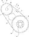
- FIG. 2 is a schematic view of the transmission unit of FIG. 1 .
- FIG. 1 schematically illustrates a motor vehicle 10 and a motor vehicle steering system 27 .
- the steering system 27 including a driver operated steering mechanism 11 , preferably a steering wheel.
- the steering mechanism 11 connects to a steering mechanism base 17 .
- the steering mechanism base 17 including a steering mechanism drive, for example, an electric motor, that applies a torque to the steering mechanism 11 .
- the steering mechanism base may also include a sensor, configured to detect the position of the steering mechanism, for example, a steering wheel angle.
- the steering system 27 including a steering gear 12 , wherein the steering mechanism 11 and the steering gear 12 are mechanically separated from one another. Wheels 13 of the motor vehicle 10 are mechanically coupled to the steering gear 12 .
- a drive unit 14 for example, an electric motor, of the steering system 27 drives the steering gear 12 .
- a transmission unit 15 connects the drive unit 14 to the steering gear 12 .
- a control unit 16 controls the drive unit 14 of the steering system 27 and transmits to the drive unit 14 steering commands input through the steering mechanism 11 .
- the transmission unit 15 transmits to the steering gear 12 a torque generated by the drive unit 14 .
- the transmission unit 15 includes a redundancy.
- the transmission unit 15 includes a first transmission path 24 and a second transmission path 25 .
- Each of the transmission paths 24 , 25 configured to transmit torque generated by the drive unit 14 to the steering gear 12 .
- the transmission unit 15 engaging only one of the transmission paths 24 , 25 .
- the first transmission path 24 transmits to the steering gear 12 the torque generated by the drive unit 14
- the second transmission path 25 does not transmit torque generated by the drive unit 14 to the steering gear 12 .
- the second transmission path 25 transmits torque generated by the drive unit 14 to the steering gear 12 , while the first transmission path 24 does not transmit torque generated by the drive unit 14 to the steering gear.
- the first transmission path 24 serves as the normal transmission path
- the second transmission path 25 serves as a backup or emergency transmission path should the first transmission path 24 fail.
- the first transmission path 24 is a belt drive and the second transmission path 25 is a gear drive.
- FIG. 2 schematically illustrates the transmission unit 15 in an exemplary embodiment, wherein the elements of the second transmission path 25 are represented with a dashed line.
- Another embodiment includes the first transmission path 24 configured as a gear drive and the second transmission path 25 as a belt drive.
- the belt drive of the first transmission path 24 includes a first wheel 18 receiving a torque generated by the drive unit 14 and a second wheel 19 delivering the torque generated by the drive unit 14 to the steering gear 12 .
- the first wheel 18 and the second wheel 19 are belt pulleys connected, in a torque-transmitting manner, by a belt 20 .
- the belt 20 in the normal state subjected to a predetermined or certain mechanical tension 26 .
- the gear drive of the second transmission path 25 lies in the same axis as the first transmission path 24 and includes a first additional wheel 21 receiving the torque generated by the drive unit 14 and a second additional wheel 22 delivering the torque generated by the drive unit 14 to the steering gear.
- the first additional wheel 21 and the second additional wheel 22 are, for example, gearwheels, connected in a torque-transmitting manner, via a connecting wheel 23 , which may also be a gearwheel.
- the backup state engages when the first transmission path 24 fails.
- interruption of torque transmission in the second transmission path 25 occurs when the first additional wheel 21 and connecting wheel 23 are not engaged, the second additional wheel 22 and connecting wheel 23 are not engaged, or neither the first additional wheel 21 nor the second additional wheel 22 engages connecting wheel 23 , for example, the connecting wheel 23 is displaced parallel to the steering gear 12 .
- the torque path also interrupted when the first additional wheel 21 and drive unit 14 are not connected in a torque-transmitting manner or second additional wheel 22 and steering gear 12 are not connected in a torque-transmitting manner.
- the first additional wheel 21 receives the torque generated by the drive unit 14 and the second additional wheel 22 delivers the torque generated by the drive unit 14 to the steering gear 12 .
- the first additional wheel 21 and the second additional wheel 22 are belt pulleys connected, in the backup state, in a torque-transmitting manner, via a second belt.
- the torque transmission of the second transmission path 25 interrupted when the first additional wheel 21 and drive unit 14 are not connected in a torque-transmitting manner or the second additional wheel 22 and steering gear 12 are not connected in a torque-transmitting manner.
- the transmission unit 15 automatically engages the second transmission path 25 .
- the transmission unit 15 For example, mounting the first additional wheel 21 or the second additional wheel 22 on its associated shaft with a torsional play. A twisting motion, triggered by the failure of the first transmission path 24 , creates a force closure or a forms closure between the additional wheel 21 , 22 and the respective shaft.
- tension 26 in the belt may deactivate the second transmission path 25 .
- the tension 26 in the belt 20 keeps the second transmission path 25 from engaging, and in the backup state, without the belt tension, the second transmission path 25 engages.
- the transmission unit 15 may include a clutch which, in an open state, decouples the second transmission path 25 and in a closed state couples the second transmission path 25 .
- couples and decouples relates to torque transfer in or through the particular transmission path.
- the tension in the belt 20 keeps the clutch 28 in an open state, for example, if there is tension 26 in the belt 20 the clutch is kept open.
- the belt 20 fails or cannot hold tension, it does not transmit torque from the first wheel 18 to the second wheel 19 .
- Belt failure for example, belt breakage, that prevents the belt 20 from maintaining the requisite tension 26 causes the clutch 28 to close or engage and transfer torque from the first additional wheel 21 through the connecting wheel 23 to the second additional wheel 22 .
- the belt tension keeps one of the additional wheels 21 , 22 , or the connecting wheel 23 , from engaging. As long as the belt 20 does not fail, one of the additional wheels 21 , 22 or the connecting wheel 23 is held a non-engagement position keeping the second transmission path 25 decoupled. Failure of the belt 20 removes the belt tension, without the belt tension one of the additional wheels 21 , 22 , or the connecting wheel 23 shifts from the non-engagement position into an engagement position.
- the motor vehicle 10 includes a mechanism that recognizes when one of the transmission paths 24 , 25 fails.
- the motor vehicle 10 includes a sensor, for example, a torque sensor, that detects whether, via the second transmission path 25 , a torque is transmitted.
- the motor vehicle 10 configured to issue a message upon recognizing failure of one of the transmission paths 24 , 25 .
- the motor vehicle includes a steering mechanism 11 , a steering gear 12 mechanically decoupled from the steering mechanism 11 , a drive unit 14 driving the steering gear 12 , and a transmission unit 15 connecting the drive unit 14 in a torque-transmitting manner to the steering gear 12 .
- the transmission unit 15 having a redundancy improving the operating reliability of the vehicle steering without an additional drive unit.
- the transmission unit 15 has a first transmission path 24 and a second transmission path 25 .
- the first and the second transmission path 24 , 25 can respectively be a belt drive or a gear drive.
- the second transmission path 25 drives the steering gear 12 .
- the transmission unit 15 configured to automatically engage the second transmission path 25 if a failure of the first transmission path occurs 24 .
- One example of the transmission unit 15 includes a clutch, which in the open state decouples the second transmission path and in the closed state couples this same.
- the clutch kept open by tension 26 on a belt 20 of the belt drive of the first transmission path 24 .
- a further example of the transmission unit 15 includes the first transmission path 24 being a belt drive and the second transmission path 25 a gear drive.
- the transmission unit 15 configured such that belt tension of the belt 20 of the first transmission path 24 keeps the second transmission path 25 decoupled. Loss of belt tension results in an automatic switchover from normal operation into backup operation in a simple manner.
- the motor vehicle can be configured to recognize when one of the transmission paths 24 , 25 fails. Because of the redundant design, the driver notices nothing of the failure of one of the transmission paths. Upon recognizing a failure, a warning message can issue informing the driver.
Landscapes
- Engineering & Computer Science (AREA)
- Chemical & Material Sciences (AREA)
- Combustion & Propulsion (AREA)
- Transportation (AREA)
- Mechanical Engineering (AREA)
- Power Steering Mechanism (AREA)
Abstract
Description
Claims (7)
Applications Claiming Priority (3)
| Application Number | Priority Date | Filing Date | Title |
|---|---|---|---|
| DEDE102018202611.4 | 2018-02-21 | ||
| DE102018202611.4A DE102018202611A1 (en) | 2018-02-21 | 2018-02-21 | Motor vehicle with mechanically decoupled steering |
| DE102018202611.4 | 2018-02-21 |
Publications (2)
| Publication Number | Publication Date |
|---|---|
| US20190256127A1 US20190256127A1 (en) | 2019-08-22 |
| US11001296B2 true US11001296B2 (en) | 2021-05-11 |
Family
ID=67482154
Family Applications (1)
| Application Number | Title | Priority Date | Filing Date |
|---|---|---|---|
| US16/282,057 Active 2039-11-21 US11001296B2 (en) | 2018-02-21 | 2019-02-21 | Motor vehicle steering system |
Country Status (2)
| Country | Link |
|---|---|
| US (1) | US11001296B2 (en) |
| DE (1) | DE102018202611A1 (en) |
Citations (9)
| Publication number | Priority date | Publication date | Assignee | Title |
|---|---|---|---|---|
| DE19902556A1 (en) | 1999-01-22 | 2000-07-27 | Mercedes Benz Lenkungen Gmbh | Motor vehicle steering gear with redundant drive has two servo motors acting on common toothed rack that are engaged via steering box and are in form of electric motors |
| DE10310505A1 (en) | 2003-03-11 | 2004-09-23 | Zf Lenksysteme Gmbh | Servo steering system for automobile has 2 parallel belt drives between electric motor shaft and intermediate drive for reducing noise emission level |
| DE10316599A1 (en) | 2003-04-11 | 2004-11-18 | Contitech Antriebssysteme Gmbh | Gear device for drives of motor vehicle steering systems |
| US20050155809A1 (en) | 2004-01-20 | 2005-07-21 | Krzesicki Richard M. | Mechanical clutch coupling back-up for electric steering system |
| US8297401B1 (en) | 2011-11-10 | 2012-10-30 | The Gates Corporation | Vehicle steering system transmission |
| US20150298722A1 (en) | 2012-10-30 | 2015-10-22 | Volkswagen Ag | Device for assisting or automatic guiding of a motor vehicle |
| US20170057541A1 (en) | 2015-08-31 | 2017-03-02 | Steering Solutions Ip Holding Corporation | Overload protection for belt drive mechanism |
| WO2017060042A1 (en) | 2015-10-06 | 2017-04-13 | Robert Bosch Automotive Steering Gmbh | Method for operating a steering system of a motor vehicle |
| US20180170427A1 (en) * | 2016-12-21 | 2018-06-21 | Ontario Drive & Gear Limited | Vehicle drive transmission and electrically assisted steering system |
-
2018
- 2018-02-21 DE DE102018202611.4A patent/DE102018202611A1/en active Pending
-
2019
- 2019-02-21 US US16/282,057 patent/US11001296B2/en active Active
Patent Citations (10)
| Publication number | Priority date | Publication date | Assignee | Title |
|---|---|---|---|---|
| DE19902556A1 (en) | 1999-01-22 | 2000-07-27 | Mercedes Benz Lenkungen Gmbh | Motor vehicle steering gear with redundant drive has two servo motors acting on common toothed rack that are engaged via steering box and are in form of electric motors |
| DE10310505A1 (en) | 2003-03-11 | 2004-09-23 | Zf Lenksysteme Gmbh | Servo steering system for automobile has 2 parallel belt drives between electric motor shaft and intermediate drive for reducing noise emission level |
| DE10316599A1 (en) | 2003-04-11 | 2004-11-18 | Contitech Antriebssysteme Gmbh | Gear device for drives of motor vehicle steering systems |
| US20050155809A1 (en) | 2004-01-20 | 2005-07-21 | Krzesicki Richard M. | Mechanical clutch coupling back-up for electric steering system |
| US8297401B1 (en) | 2011-11-10 | 2012-10-30 | The Gates Corporation | Vehicle steering system transmission |
| US20150298722A1 (en) | 2012-10-30 | 2015-10-22 | Volkswagen Ag | Device for assisting or automatic guiding of a motor vehicle |
| US20170057541A1 (en) | 2015-08-31 | 2017-03-02 | Steering Solutions Ip Holding Corporation | Overload protection for belt drive mechanism |
| US9845106B2 (en) * | 2015-08-31 | 2017-12-19 | Steering Solutions Ip Holding Corporation | Overload protection for belt drive mechanism |
| WO2017060042A1 (en) | 2015-10-06 | 2017-04-13 | Robert Bosch Automotive Steering Gmbh | Method for operating a steering system of a motor vehicle |
| US20180170427A1 (en) * | 2016-12-21 | 2018-06-21 | Ontario Drive & Gear Limited | Vehicle drive transmission and electrically assisted steering system |
Also Published As
| Publication number | Publication date |
|---|---|
| DE102018202611A1 (en) | 2019-08-22 |
| US20190256127A1 (en) | 2019-08-22 |
Similar Documents
| Publication | Publication Date | Title |
|---|---|---|
| KR101708083B1 (en) | Fail safe operational steering system for autonomous driving | |
| US10875571B2 (en) | Motor control system and electric power steering system | |
| US9751555B2 (en) | Steering system for vehicle | |
| US4869334A (en) | Electric motor-driven power steering apparatus | |
| US20210253157A1 (en) | Steer-by-wire architectures having a second steering angle sensor | |
| CN107200058B (en) | Steering system for steerable vehicle | |
| US20060271260A1 (en) | Vehicle control system | |
| CN107776655B (en) | Steering device for vehicle | |
| US20220388487A1 (en) | Brake apparatus for vehicle and control method therefor | |
| US7127341B2 (en) | Failsafe steering device for steer-by-wire system | |
| JP5334973B2 (en) | A system that controls the release of the automatic parking brake device installed in automobiles | |
| US20220306149A1 (en) | Device for controlling a steering angle or braking of an autonomous motor vehicle and vehicle including the device | |
| CN108351025B (en) | Method and monitoring device for operating a motor vehicle | |
| US9890800B2 (en) | Drive system for ground maintenance vehicle | |
| US20150360716A1 (en) | Independent Supplementary Electrically Assisted Power Steering System | |
| WO2013084277A1 (en) | Electronic control device having power supply voltage monitoring function and vehicle steering control device equipped with same | |
| CN104040224B (en) | For method and the controller of power transmission based part | |
| KR101784751B1 (en) | Finding method for locked steering apparatus and navigation method by the same and unlocking process for the locked steering apparatus by the same | |
| JP2013504014A (en) | Clutch actuator | |
| JP5239245B2 (en) | Vehicle steering control device | |
| US11001296B2 (en) | Motor vehicle steering system | |
| JP2002213331A (en) | Drive train operating method and drive train adjusting device | |
| US20250115286A1 (en) | Steering device and steering control device | |
| CN111791701A (en) | Safety mechanism for travel drives of mobile work machines and travel drives with safety mechanisms | |
| JP4884778B2 (en) | Vehicle control device |
Legal Events
| Date | Code | Title | Description |
|---|---|---|---|
| FEPP | Fee payment procedure |
Free format text: ENTITY STATUS SET TO UNDISCOUNTED (ORIGINAL EVENT CODE: BIG.); ENTITY STATUS OF PATENT OWNER: LARGE ENTITY |
|
| STPP | Information on status: patent application and granting procedure in general |
Free format text: NOTICE OF ALLOWANCE MAILED -- APPLICATION RECEIVED IN OFFICE OF PUBLICATIONS |
|
| AS | Assignment |
Owner name: FORD GLOBAL TECHNOLOGIES, LLC, MICHIGAN Free format text: ASSIGNMENT OF ASSIGNORS INTEREST;ASSIGNORS:ENGELS, FRANK PETER;RATH, FLORIAN;SIGNING DATES FROM 20210326 TO 20210406;REEL/FRAME:055864/0744 |
|
| STPP | Information on status: patent application and granting procedure in general |
Free format text: PUBLICATIONS -- ISSUE FEE PAYMENT RECEIVED |
|
| STPP | Information on status: patent application and granting procedure in general |
Free format text: PUBLICATIONS -- ISSUE FEE PAYMENT VERIFIED |
|
| STCF | Information on status: patent grant |
Free format text: PATENTED CASE |
|
| MAFP | Maintenance fee payment |
Free format text: PAYMENT OF MAINTENANCE FEE, 4TH YEAR, LARGE ENTITY (ORIGINAL EVENT CODE: M1551); ENTITY STATUS OF PATENT OWNER: LARGE ENTITY Year of fee payment: 4 |