US11001242B2 - Braking control device for vehicle - Google Patents
Braking control device for vehicle Download PDFInfo
- Publication number
- US11001242B2 US11001242B2 US16/334,585 US201716334585A US11001242B2 US 11001242 B2 US11001242 B2 US 11001242B2 US 201716334585 A US201716334585 A US 201716334585A US 11001242 B2 US11001242 B2 US 11001242B2
- Authority
- US
- United States
- Prior art keywords
- pressing force
- current
- wheel
- target
- axis
- Prior art date
- Legal status (The legal status is an assumption and is not a legal conclusion. Google has not performed a legal analysis and makes no representation as to the accuracy of the status listed.)
- Active, expires
Links
Images


Classifications
-
- B—PERFORMING OPERATIONS; TRANSPORTING
- B60—VEHICLES IN GENERAL
- B60T—VEHICLE BRAKE CONTROL SYSTEMS OR PARTS THEREOF; BRAKE CONTROL SYSTEMS OR PARTS THEREOF, IN GENERAL; ARRANGEMENT OF BRAKING ELEMENTS ON VEHICLES IN GENERAL; PORTABLE DEVICES FOR PREVENTING UNWANTED MOVEMENT OF VEHICLES; VEHICLE MODIFICATIONS TO FACILITATE COOLING OF BRAKES
- B60T8/00—Arrangements for adjusting wheel-braking force to meet varying vehicular or ground-surface conditions, e.g. limiting or varying distribution of braking force
- B60T8/17—Using electrical or electronic regulation means to control braking
- B60T8/176—Brake regulation specially adapted to prevent excessive wheel slip during vehicle deceleration, e.g. ABS
- B60T8/1761—Brake regulation specially adapted to prevent excessive wheel slip during vehicle deceleration, e.g. ABS responsive to wheel or brake dynamics, e.g. wheel slip, wheel acceleration or rate of change of brake fluid pressure
- B60T8/17616—Microprocessor-based systems
-
- B—PERFORMING OPERATIONS; TRANSPORTING
- B60—VEHICLES IN GENERAL
- B60T—VEHICLE BRAKE CONTROL SYSTEMS OR PARTS THEREOF; BRAKE CONTROL SYSTEMS OR PARTS THEREOF, IN GENERAL; ARRANGEMENT OF BRAKING ELEMENTS ON VEHICLES IN GENERAL; PORTABLE DEVICES FOR PREVENTING UNWANTED MOVEMENT OF VEHICLES; VEHICLE MODIFICATIONS TO FACILITATE COOLING OF BRAKES
- B60T13/00—Transmitting braking action from initiating means to ultimate brake actuator with power assistance or drive; Brake systems incorporating such transmitting means, e.g. air-pressure brake systems
- B60T13/10—Transmitting braking action from initiating means to ultimate brake actuator with power assistance or drive; Brake systems incorporating such transmitting means, e.g. air-pressure brake systems with fluid assistance, drive, or release
- B60T13/12—Transmitting braking action from initiating means to ultimate brake actuator with power assistance or drive; Brake systems incorporating such transmitting means, e.g. air-pressure brake systems with fluid assistance, drive, or release the fluid being liquid
- B60T13/16—Transmitting braking action from initiating means to ultimate brake actuator with power assistance or drive; Brake systems incorporating such transmitting means, e.g. air-pressure brake systems with fluid assistance, drive, or release the fluid being liquid using pumps directly, i.e. without interposition of accumulators or reservoirs
- B60T13/161—Systems with master cylinder
- B60T13/165—Master cylinder integrated or hydraulically coupled with booster
- B60T13/166—Part of the system directly actuated by booster pressure
-
- B—PERFORMING OPERATIONS; TRANSPORTING
- B60—VEHICLES IN GENERAL
- B60T—VEHICLE BRAKE CONTROL SYSTEMS OR PARTS THEREOF; BRAKE CONTROL SYSTEMS OR PARTS THEREOF, IN GENERAL; ARRANGEMENT OF BRAKING ELEMENTS ON VEHICLES IN GENERAL; PORTABLE DEVICES FOR PREVENTING UNWANTED MOVEMENT OF VEHICLES; VEHICLE MODIFICATIONS TO FACILITATE COOLING OF BRAKES
- B60T13/00—Transmitting braking action from initiating means to ultimate brake actuator with power assistance or drive; Brake systems incorporating such transmitting means, e.g. air-pressure brake systems
- B60T13/10—Transmitting braking action from initiating means to ultimate brake actuator with power assistance or drive; Brake systems incorporating such transmitting means, e.g. air-pressure brake systems with fluid assistance, drive, or release
- B60T13/66—Electrical control in fluid-pressure brake systems
- B60T13/662—Electrical control in fluid-pressure brake systems characterised by specified functions of the control system components
-
- B—PERFORMING OPERATIONS; TRANSPORTING
- B60—VEHICLES IN GENERAL
- B60T—VEHICLE BRAKE CONTROL SYSTEMS OR PARTS THEREOF; BRAKE CONTROL SYSTEMS OR PARTS THEREOF, IN GENERAL; ARRANGEMENT OF BRAKING ELEMENTS ON VEHICLES IN GENERAL; PORTABLE DEVICES FOR PREVENTING UNWANTED MOVEMENT OF VEHICLES; VEHICLE MODIFICATIONS TO FACILITATE COOLING OF BRAKES
- B60T13/00—Transmitting braking action from initiating means to ultimate brake actuator with power assistance or drive; Brake systems incorporating such transmitting means, e.g. air-pressure brake systems
- B60T13/10—Transmitting braking action from initiating means to ultimate brake actuator with power assistance or drive; Brake systems incorporating such transmitting means, e.g. air-pressure brake systems with fluid assistance, drive, or release
- B60T13/66—Electrical control in fluid-pressure brake systems
- B60T13/68—Electrical control in fluid-pressure brake systems by electrically-controlled valves
- B60T13/686—Electrical control in fluid-pressure brake systems by electrically-controlled valves in hydraulic systems or parts thereof
-
- B—PERFORMING OPERATIONS; TRANSPORTING
- B60—VEHICLES IN GENERAL
- B60T—VEHICLE BRAKE CONTROL SYSTEMS OR PARTS THEREOF; BRAKE CONTROL SYSTEMS OR PARTS THEREOF, IN GENERAL; ARRANGEMENT OF BRAKING ELEMENTS ON VEHICLES IN GENERAL; PORTABLE DEVICES FOR PREVENTING UNWANTED MOVEMENT OF VEHICLES; VEHICLE MODIFICATIONS TO FACILITATE COOLING OF BRAKES
- B60T13/00—Transmitting braking action from initiating means to ultimate brake actuator with power assistance or drive; Brake systems incorporating such transmitting means, e.g. air-pressure brake systems
- B60T13/74—Transmitting braking action from initiating means to ultimate brake actuator with power assistance or drive; Brake systems incorporating such transmitting means, e.g. air-pressure brake systems with electrical assistance or drive
- B60T13/745—Transmitting braking action from initiating means to ultimate brake actuator with power assistance or drive; Brake systems incorporating such transmitting means, e.g. air-pressure brake systems with electrical assistance or drive acting on a hydraulic system, e.g. a master cylinder
-
- B—PERFORMING OPERATIONS; TRANSPORTING
- B60—VEHICLES IN GENERAL
- B60T—VEHICLE BRAKE CONTROL SYSTEMS OR PARTS THEREOF; BRAKE CONTROL SYSTEMS OR PARTS THEREOF, IN GENERAL; ARRANGEMENT OF BRAKING ELEMENTS ON VEHICLES IN GENERAL; PORTABLE DEVICES FOR PREVENTING UNWANTED MOVEMENT OF VEHICLES; VEHICLE MODIFICATIONS TO FACILITATE COOLING OF BRAKES
- B60T13/00—Transmitting braking action from initiating means to ultimate brake actuator with power assistance or drive; Brake systems incorporating such transmitting means, e.g. air-pressure brake systems
- B60T13/74—Transmitting braking action from initiating means to ultimate brake actuator with power assistance or drive; Brake systems incorporating such transmitting means, e.g. air-pressure brake systems with electrical assistance or drive
- B60T13/746—Transmitting braking action from initiating means to ultimate brake actuator with power assistance or drive; Brake systems incorporating such transmitting means, e.g. air-pressure brake systems with electrical assistance or drive and mechanical transmission of the braking action
-
- B—PERFORMING OPERATIONS; TRANSPORTING
- B60—VEHICLES IN GENERAL
- B60T—VEHICLE BRAKE CONTROL SYSTEMS OR PARTS THEREOF; BRAKE CONTROL SYSTEMS OR PARTS THEREOF, IN GENERAL; ARRANGEMENT OF BRAKING ELEMENTS ON VEHICLES IN GENERAL; PORTABLE DEVICES FOR PREVENTING UNWANTED MOVEMENT OF VEHICLES; VEHICLE MODIFICATIONS TO FACILITATE COOLING OF BRAKES
- B60T7/00—Brake-action initiating means
- B60T7/02—Brake-action initiating means for personal initiation
- B60T7/04—Brake-action initiating means for personal initiation foot actuated
- B60T7/042—Brake-action initiating means for personal initiation foot actuated by electrical means, e.g. using travel or force sensors
-
- B—PERFORMING OPERATIONS; TRANSPORTING
- B60—VEHICLES IN GENERAL
- B60T—VEHICLE BRAKE CONTROL SYSTEMS OR PARTS THEREOF; BRAKE CONTROL SYSTEMS OR PARTS THEREOF, IN GENERAL; ARRANGEMENT OF BRAKING ELEMENTS ON VEHICLES IN GENERAL; PORTABLE DEVICES FOR PREVENTING UNWANTED MOVEMENT OF VEHICLES; VEHICLE MODIFICATIONS TO FACILITATE COOLING OF BRAKES
- B60T8/00—Arrangements for adjusting wheel-braking force to meet varying vehicular or ground-surface conditions, e.g. limiting or varying distribution of braking force
- B60T8/17—Using electrical or electronic regulation means to control braking
- B60T8/171—Detecting parameters used in the regulation; Measuring values used in the regulation
-
- B—PERFORMING OPERATIONS; TRANSPORTING
- B60—VEHICLES IN GENERAL
- B60T—VEHICLE BRAKE CONTROL SYSTEMS OR PARTS THEREOF; BRAKE CONTROL SYSTEMS OR PARTS THEREOF, IN GENERAL; ARRANGEMENT OF BRAKING ELEMENTS ON VEHICLES IN GENERAL; PORTABLE DEVICES FOR PREVENTING UNWANTED MOVEMENT OF VEHICLES; VEHICLE MODIFICATIONS TO FACILITATE COOLING OF BRAKES
- B60T8/00—Arrangements for adjusting wheel-braking force to meet varying vehicular or ground-surface conditions, e.g. limiting or varying distribution of braking force
- B60T8/17—Using electrical or electronic regulation means to control braking
- B60T8/176—Brake regulation specially adapted to prevent excessive wheel slip during vehicle deceleration, e.g. ABS
- B60T8/1761—Brake regulation specially adapted to prevent excessive wheel slip during vehicle deceleration, e.g. ABS responsive to wheel or brake dynamics, e.g. wheel slip, wheel acceleration or rate of change of brake fluid pressure
Definitions
- the present invention relates to a braking control device for a vehicle.
- Patent Document 1 discloses a brake device to improve responsiveness to the generation of a braking force without increasing the size of an electric motor for driving an electric braking-force generator.
- the brake device includes a target brake-fluid pressure calculator M 1 that calculates target brake-fluid pressure to be generated in a slave cylinder, a differential unit M 2 that calculates the change rate of the target brake-fluid pressure by differentiating the target brake-fluid pressure with respect to time, a field current calculator M 3 that calculates the field current-command value of an electric motor driving a slave cylinder on the basis of the change rate of the target brake-fluid pressure, and an electric motor controller M 4 that performs field weakening control of the electric motor on the basis of the field current-command value.
- a case where the change rate of the target brake-fluid pressure is large is an emergency where a braking force needs to be sharply increased; and the brake device increases the amount of a weak field of the electric motor by increasing the field current-command value at this time, increases the rotational speed of the electric motor to operate the slave cylinder at a high speed, and improves responsiveness to the generation of a braking force.
- Patent Document 2 discloses a brake system to further improve responsiveness to a brake force generated by an electric actuator with a simple structure.
- the brake system controls the driving of a motor-driven cylinder 13 , which applies brake fluid pressure to a wheel cylinder, by performing field weakening control in a case where a deviation ⁇ between a target motor angle ⁇ t obtained according to the amount of a brake operation and an actual motor angle ⁇ m is large.
- a motor angle rotation angle
- the motor angle can be detected with high accuracy by a publicly known simple and inexpensive rotation sensor or the like. Accordingly, the variation range of the motor angle is widened, so that braking responsiveness can be easily improved.
- a deviation of the motor angle is generated in a transient state immediately after the start of field weakening control without being affected by a change in load stiffness, and field weakening control can continue to be executed. Accordingly, since a variation in the response characteristics of the motor is reduced, stable response characteristics is obtained.
- An applicant is developing a braking control device for a vehicle that generates braking torque by an electric motor and suppresses an increase in wheel slip at the time of start of execution of slip-suppression control for a wheel.
- the slip-suppression control for a wheel which controls an electric motor on the basis of the slip state quantity of a wheel to reduce the braking torque of the wheel, is executed as disclosed in Patent Document 3.
- suddenly stop control for suddenly stopping the rotational drive of the electric motor is executed on the basis of the slip state quantity of a wheel.
- Suddenly stop control is started under a condition where the slip-suppression control for a wheel is not executed.
- “Control for stepwise changing the amount of current, which flows in an electric motor, to a preset limit current amount corresponding to a direction where the electric motor is decelerated” can be executed as the suddenly stop control.
- Patent Documents 1 and 2 disclose devices that improve responsiveness to a braking force by field weakening control (also referred to as control for weakening magnetic fluxes) performed by allowing a negative current to flow along a d axis of the electric motor.
- field weakening control also referred to as control for weakening magnetic fluxes
- a time delay for a braking force is still present. For this reason, there may be a case where excessive wheel slip occurs due to the time delay at the time of execution of control for suppressing wheel slip.
- An actual pressing force (actual pressing force) Fpa is increased on the basis of a deviation eFp between a command pressing force Fps and an actual pressing force Fpa by pressing force-feedback control so that a deviation eFp approaches “0”.
- a time delay is present in an increase in the actual pressing force Fpa with respect to an increase in the command pressing force Fps. For this reason, the actual pressing force Fpa is increased as illustrated by a solid line.
- the command pressing force Fps at the time u 1 has a command value fp 0 and is larger than an actual value fp 1 .
- the command pressing force Fps is reduced sharply on the basis of the execution of antilock brake control, but the command pressing force Fps is larger than the actual pressing force Fpa until a time u 2 . For this reason, the actual pressing force Fpa is controlled by pressing force-feedback control so as match the command pressing force Fps.
- the actual pressing force Fpa is increased up to a value fp 2 without being reduced. Since the command pressing force Fps becomes smaller than the actual pressing force Fpa after the time u 2 , the actual pressing force Fpa is reduced from the value fp 2 but a timing when the actual pressing force Fpa starts is delayed. Wheel slip may be excessively increased due to this time delay. Accordingly, it is desired that excessive wheel slip caused by the time delay of an increase in a pressing force is suppressed.
- Patent Document 1 JP-A-2008-184057
- Patent Document 2 JP-A-2012-131293
- Patent Document 3 JP-A-2014-051198
- An object of the invention is to provide a braking control device that can more effectively suppress excessive wheel slip at the time of start of control for suppressing wheel slip.
- a braking control device for a vehicle drives an electric motor (MTR) on the basis of a command pressing force (Fps) corresponding to a braking force required for a wheel (WH) of a vehicle and presses a friction member (MS) against a rotation member (KT) fixed to the wheel (WH) to generate a braking force on the wheel (WH).
- MTR electric motor
- Fps command pressing force
- MS friction member
- KT rotation member
- the braking control device for a vehicle includes a wheel speed sensor (VWA) that detects a speed (Vwa) of the wheel (WH); a pressing force sensor (FPA) that detects an actual pressing force (Fpa) applied to the rotation member (KT) by the friction member (MS); and a controller (ECU) that calculates a target pressing force (Fpt) on the basis of the command pressing force (Fps) and controls the electric motor (MTR) so that the target pressing force (Fpt) and the actual pressing force (Fpa) match each other.
- VWA wheel speed sensor
- FPA pressing force sensor
- KT an actual pressing force applied to the rotation member
- MS friction member
- ECU that calculates a target pressing force (Fpt) on the basis of the command pressing force (Fps) and controls the electric motor (MTR) so that the target pressing force (Fpt) and the actual pressing force (Fpa) match each other.
- Slp slip state quantity representing the degree of slippage of the wheel on the basis of the speed (Vwa) of the wheel (WH)
- slip-suppression control which reduces the degree of slippage of the wheel (WH), on the basis of the slip state quantity (Slp)
- Fps command pressing force
- Fpt target pressing force
- the controller sharply reduces the command pressing force (Fps) to a value (fp 2 ) of the actual pressing force (Fpa), which is obtained at the time (t 2 ) of start of execution of the slip-suppression control, to calculate the target pressing force (Fpt) at the time (t 2 ) of start of execution of the slip-suppression control.
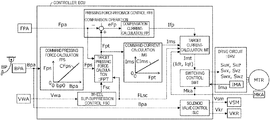
- FIG. 1 is a diagram illustrating the overall configuration of a vehicle on which a braking control device BCS for a vehicle according to the invention is mounted.
- FIG. 2 is a functional block diagram illustrating processing performed in a controller ECU.
- FIG. 3 is a flowchart illustrating processing performed in a wheel slip-suppression control block FSC and a target pressing force-calculation block FPT.
- FIG. 4 is a flowchart illustrating processing performed in a target current-calculation block IMT (particularly, the flow of the processing in a case where wheel slip-suppression control is not executed).
- FIG. 5 is a flowchart illustrating processing performed in the target current-calculation block IMT (particularly, the flow of the processing in a case where wheel slip-suppression control is executed).
- FIG. 6 is a characteristic diagram illustrating the processing performed in the target current-calculation block IMT.
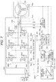
- FIG. 7 is a schematic diagram illustrating processing, which is performed in a switching control block SWT, and a drive circuit DRV of a three-phase brushless motor.
- FIG. 8 is a time series diagram illustrating the effects of the braking control device BCS for a vehicle according to the invention.
- FIG. 9 is a time series diagram illustrating a problem caused by the time delay of an actual value Fpa with respect to a command value Fps of a pressing force.
- a braking control device BCS according to the invention will be described with reference to a diagram of FIG. 1 that illustrates the overall configuration of a vehicle.
- components, calculation processing, signals, characteristics, and values denoted by the same reference numerals will fulfill the same functions. Accordingly, repeated description will be omitted.
- a vehicle including the braking control device BCS is provided with a braking operation member BP, a braking-operation-amount sensor BPA, a controller ECU, a master cylinder MC, a stroke simulator SSM, a simulator shut-off valve VSM, a pressurizing unit KAU, a switching valve VKR, a master cylinder pipe HMC, a wheel cylinder pipe HWC, and a pressurizing cylinder pipe HKC.
- each wheel WH of the vehicle is provided with a brake caliper CP, a wheel cylinder WC, a rotation member KT, and a friction member MS.
- the braking operation member (for example, a brake pedal) BP is a member that is operated by a driver to reduce the speed of the vehicle.
- the braking operation member BP is operated, so that braking torque applied to the wheel WH is adjusted and a braking force is generated on the wheel WH.
- the rotation member (for example, a brake disc) KT is fixed to the wheel WH of the vehicle.
- the brake caliper CP is disposed so as to hold the rotation member KT.
- the brake caliper (also simply referred to as a caliper) CP is provided with the wheel cylinder WC.
- Fluid pressure in the wheel cylinder WC of the caliper CP is adjusted (increased or reduced), so that a piston provided in the wheel cylinder WC is moved (moved forward or moved rearward) relative to the rotation member KT.
- the friction member for example, a brake pad
- the rotation member KT and the wheel WH are fixed to each other by a fixing shaft DS so as to be rotated integrally with each other. For this reason, braking torque (braking force) is generated on the wheel WH by a friction force that is caused by the pressing force. Accordingly, a braking force (required braking force) required for the wheel WH is achieved according to a target value of the pressing force.
- the braking operation member BP is provided with the braking-operation-amount sensor (also simply referred to as an operation-amount sensor) BPA.
- the operation amount Bpa of the braking operation member (brake pedal) BP which is operated by a driver, is detected by the operation-amount sensor BPA.
- the operation-amount sensor BPA is employed as the braking-operation-amount sensor BPA.
- the operation-amount sensor BPA is the generic name of the fluid pressure sensor of the master cylinder, the operating displacement sensor, and the operating force sensor.
- the braking operation amount Bpa is determined on the basis of at least one of the fluid pressure of the master cylinder MC, the operating displacement of the braking operation member BP, and the operating force of the braking operation member BP.
- the operation amount Bpa is input to the controller ECU.
- the controller (electronic control unit) ECU includes an electric circuit board on which a microprocessor and the like are mounted, and a control algorithm that is programmed in the microprocessor.
- the controller ECU controls the pressurizing unit KAU (particularly, an electric motor MTR), the shut-off valve VSM, and the switching valve VKR on the basis of the braking operation amount Bpa.
- signals (Sux and the like) which are required to control the electric motor MTR, the shut-off valve VSM, and the switching valve VKR, are calculated on the basis of the programmed control algorithm, and are output from the controller ECU.
- the controller ECU In a case where the braking operation amount Bpa becomes equal to or larger than a predetermined value bp 0 , the controller ECU outputs a drive signal Vsm that allows the shut-off valve VSM to be switched to an open position, to the solenoid valve VSM and outputs a drive signal Vkr, which allows the switching valve VKR to make the pressurizing cylinder pipe HKC and the wheel cylinder pipe HWC be in a communication state, to the solenoid valve VKR.
- the master cylinder MC communicates with the simulator SSM and a pressurizing cylinder KCL communicates with the wheel cylinder WC.
- the controller ECU calculates drive signals (Sux and the like), which are required to drive the electric motor MTR, on the basis of the operation amount Bpa, a rotation angle Mka, and an actual pressing force Fpa (for example, the fluid pressure of the pressurizing cylinder KCL), and outputs the drive signal to a drive circuit DRV.
- the braking operation amount Bpa is detected by the braking-operation-amount sensor BPA
- an actual rotation angle Mka is detected by a rotation angle sensor MKA
- the actual pressing force Fpa is detected by a pressing force sensor FPA.
- the pressure of braking fluid which is present in the wheel cylinder WC, is controlled (maintained, increased, or reduced) by the pressurizing unit KAU that is driven by the electric motor MTR.
- the master cylinder MC is mechanically connected to the braking operation member BP through a brake rod BRD.
- the operating force (brake pedal force) of the braking operation member BP is converted into the pressure of braking fluid by the master cylinder MC.
- the master cylinder pipe HMC is connected to the master cylinder MC, and braking fluid is discharged (pumped) to the master cylinder pipe HMC from the master cylinder MC in a case where the braking operation member BP is operated.
- the master cylinder pipe HMC is a fluid passage that connects the master cylinder MC to the switching valve VKR.
- the stroke simulator (also simply referred to as a simulator) SSM is provided to generate an operating force on the braking operation member BP.
- the simulator shut-off valve (also simply referred to as a shut-off valve) VSM is provided between a fluid pressure chamber, which is provided in the master cylinder MC, and the simulator SSM.
- the shut-off valve VSM is a two-position solenoid valve that includes an open position and a closed position. In a case where the shut-off valve VSM is switched to the open position, the master cylinder MC and the simulator SSM are in a communication state. In a case where the shut-off valve VSM is present at the closed position, the master cylinder MC and the simulator SSM are in a shut-off state (non-communication state).
- the shut-off valve VSM is controlled according to the drive signal Vsm output from the controller ECU.
- a normally closed solenoid valve (NC valve) can be employed as the shut-off valve VSM.
- a piston and an elastic body are provided in the simulator SSM. Braking fluid is moved to the simulator SSM from the master cylinder MC, so that the piston is pushed by the braking fluid flowing in. A force is applied to the piston in a direction where the inflow of braking fluid is hindered by the elastic body.
- An operating force for example, a brake pedal force
- the elastic body is formed by the elastic body.
- the pressurizing unit KAU uses the electric motor MTR as a power source and discharges (pumps) braking fluid to the pressurizing cylinder pipe HKC. Then, the pressurizing unit KAU pushes (presses) the friction member MS against the rotation member KT by this pressure to apply braking torque (braking force) to the wheel WH. In other words, the pressurizing unit KAU generates a force (pressing force), which pushes the friction member MS against the rotation member KT, by the electric motor MTR.
- the pressurizing unit KAU includes the electric motor MTR, the drive circuit DRV, a power transmission mechanism DDK, a pressurizing shaft KSF, the pressurizing cylinder KCL, a pressurizing piston PKC, and the pressing force sensor FPA.
- the electric motor MTR is a power source that allows the pressurizing cylinder KCL to adjust (increase, reduce, or the like) the pressure of braking fluid present in the wheel cylinder WC.
- a three-phase brushless motor is employed as the electric motor MTR.
- the electric motor MTR includes three coils CLU, CLV, and CLW corresponding to a U phase, a V phase, and a W phase, and is driven by the drive circuit DRV.
- the electric motor MTR is provided with a rotation angle sensor MKA that detects the rotor position (rotation angle) Mka of the electric motor MTR.
- the rotation angle Mka is input to the controller ECU.
- the drive circuit DRV is an electric circuit board on which a switching element (power semiconductor device) for driving the electric motor MTR, and the like are mounted. Specifically, a three-phase bridge circuit is formed in the drive circuit DRV and a state where currents flow to the electric motor MTR is controlled on the basis of drive signals (Sux and the like).
- the drive circuit DRV is provided with current sensors (for example, current sensors) IMA that detect actual currents Ima (the generic name of actual currents of the respective phases) flowing in the electric motor MTR.
- the currents (detected values) Ima of the respective phases are input to the controller ECU.
- the power transmission mechanism DDK reduces the speed of the rotational power of the electric motor MTR, converts the rotational power into linear power, and outputs the linear power to the pressurizing shaft KSF. Specifically, since the power transmission mechanism DDK is provided with a speed reducer (not illustrated), the speed of the rotational power generated from the electric motor MTR is reduced and is output to a screw member (not illustrated). Then, the rotational power is converted into the linear power of the pressurizing shaft KSF by the screw member. That is, the power transmission mechanism DDK is a rotation/linear motion conversion mechanism.
- the pressurizing piston PKC is fixed to the pressurizing shaft KSF.
- the pressurizing piston PKC is inserted into the inner hole of the pressurizing cylinder KCL, so that a combination of the piston and the cylinder is formed.
- a sealing member (not illustrated) is provided on the outer periphery of the pressurizing piston PKC, so that fluid-tightness is ensured between the pressurizing piston PKC and the inner hole (inner wall) of the pressurizing cylinder KCL. That is, a pressurizing chamber Rkc, which is partitioned by the pressurizing cylinder KCL and the pressurizing piston PKC and is filled with braking fluid, is formed.
- the pressurizing piston PKC is moved in the direction of a central axis in the pressurizing cylinder KCL, so that the volume of the pressurizing chamber Rkc is changed. Since the volume is changed, braking fluid is moved between the pressurizing cylinder KCL and the wheel cylinder WC through the braking pipes (fluid passages) HKC and HWC. The braking fluid is sucked into or discharged from the pressurizing cylinder KCL, so that fluid pressure in the wheel cylinder WC is adjusted. As a result, a force for pressing the friction member MS against the rotation member KT is adjusted.
- a fluid pressure sensor which detects the fluid pressure Fpa of the pressurizing chamber Rkc, is built in the pressurizing unit KAU (particularly, the pressurizing cylinder KCL) as the pressing force sensor FPA.
- the fluid pressure sensor (that is, the pressing force sensor) FPA is fixed to the pressurizing cylinder KCL, and the fluid pressure sensor FPA and the pressurizing cylinder KCL are integrated as the pressurizing unit KAU.
- a detected value Fpa of a pressing force (that is, the fluid pressure of the pressurizing chamber Rkc) is input to the controller ECU.
- the pressurizing unit KAU has been described above.
- a state where the wheel cylinder WC is connected to the master cylinder MC” and “a state where the wheel cylinder WC is connected to the pressurizing cylinder KCL” are switched by the switching valve VKR.
- the switching valve VKR is controlled on the basis of the drive signal Vkr that is output from the controller ECU. Specifically, in a case where a braking operation is not performed (in a case where “Bpa ⁇ bp 0 ” is satisfied), the wheel cylinder pipe HWC communicates with the master cylinder pipe HMC through the switching valve VKR and does not communicate with (is shut off from) the pressurizing cylinder pipe HKC.
- the wheel cylinder pipe HWC is a fluid passage that is connected to the wheel cylinder WC.
- the switching valve VKR is excited on the basis of the drive signal Vkr, communication between the wheel cylinder pipe HWC and the master cylinder pipe HMC is blocked, and the wheel cylinder pipe HWC and the pressurizing cylinder pipe HKC are in a communication state.
- the driving of the electric motor MTR and the excitation of the solenoid valves VSM and VKR are performed on the basis of the operation amount Bpa of the braking operation member BP.
- the electric motor MTR is driven by the drive circuit DRV.
- the drive circuit DRV (three-phase bridge circuit) includes switching elements SUX, SUZ, SVX, SVZ, SWX, and SWZ (also simply written as “SUX to SWZ”).
- Drive signals Sux, Suz, Svx, Svz, Swx, and Swz (also simply written as “Sux to Swz) are calculated by the controller ECU, and the switching elements SUX to SWZ are controlled on the basis of the drive signals by the controller ECU.
- the drive signals Vsm and Vkr are determined by the controller ECU, and the solenoid valves VSM and VKR are controlled on the basis of the drive signals by the controller ECU.
- the controller ECU includes a command pressing force-calculation block FPS, a wheel slip-suppression control block FSC, a target pressing force-calculation block FPT, a command current-calculation block IMS, a pressing force-feedback control block FFB, a target current-calculation block IMT, a switching control block SWT, and a solenoid valve control block SLC.
- a command pressing force Fps is calculated on the basis of the braking operation amount Bpa and calculation characteristics (calculation map) CFps.
- the command pressing force Fps is a target value of fluid pressure (corresponding to a pressing force) that is generated by the pressurizing unit KAU.
- the command pressing force Fps is calculated as “0 (zero)” in a range where the braking operation amount Bpa is equal to or larger than “0 (corresponding to a case where a braking operation is not performed)” and smaller than a predetermined value bp 0 , and the command pressing force Fps is calculated so as to monotonically increase from “0” with an increase in the operation amount Bpa in a range where the operation amount Bpa is equal to or larger than the predetermined value bp 0 .
- the predetermined value bp 0 is a value corresponding to the “backlash” of the braking operation member BP, and is referred to as a “backlash value”.
- an adjustment pressing force Fsc is calculated on the basis of the wheel speed Vwa of each wheel WH.
- the adjustment pressing force Fsc is a target value that is required to execute wheel slip-suppression control.
- the “wheel slip-suppression control” is to control independently and individually the slip states of four wheels WH of a vehicle to improve the stability of the vehicle.
- the wheel slip-suppression control is at least one of antilock brake control and electronic brake force-distribution control.
- the adjustment pressing force Fsc which is required to execute at least one of antilock brake control and electronic brake force-distribution control, is calculated in the wheel slip-suppression control block FSC.
- the adjustment pressing force Fsc for antilock brake control is calculated in the wheel slip-suppression control block FSC. Specifically, the adjustment pressing force Fsc, which is required to execute antilock brake control so as to prevent wheel lock, is calculated on the basis of a result (wheel speed Vwa) acquired by a wheel speed sensor VWA that is provided on each wheel WH. For example, a wheel slip state quantity Slp (a control variable representing the state of the deceleration slip of the wheel) is calculated on the basis of the wheel speed Vwa. Then, the adjustment pressing force Fsc is determined on the basis of the wheel slip state quantity Slp.
- the wheel slip state quantity Slp is a state quantity (variable) that represents the degree of slippage of the wheel WH.
- the wheel slip state quantity Slp is calculated on the basis of at least one of a wheel slip speed and a wheel deceleration.
- the wheel slip speed is calculated on the basis of a difference between “a vehicle body speed Vxa calculated on the basis of the wheel speed Vwa of each wheel WH of the vehicle” and the wheel speed Vwa. Further, the wheel speed Vwa is differentiated with respect to time, so that the wheel deceleration is calculated.
- the predetermined quantity slx is a preset value (constant) that is required to determine whether or not to execute antilock brake control.
- the adjustment pressing force Fsc is calculated to execute electronic brake force-distribution control, which suppresses the wheel slip of a rear wheel, on the basis of the result (wheel speed Vwa) acquired by each wheel speed sensor VWA.
- an adjustment pressing force Fsc for the rear wheel is determined on the basis of the slip state quantity Slp of the rear wheel with respect to the slip state quantity Slp of the front wheel.
- electronic brake force-distribution control is started and the adjustment pressing force Fsc is calculated so that the command pressing force Fps is maintained constant.
- the predetermined speed slz is a preset value (constant) that is required to determine whether or not to execute electronic brake force-distribution control.
- a target pressing force Fpt is calculated on the basis of the command pressing force Fps and the adjustment pressing force Fsc.
- the target pressing force Fpt is a final target value of a pressing force, and corresponds to a braking force required for the wheel WH.
- the command pressing force Fps is determined as the target pressing force Fpt just as it is.
- the command pressing force Fps is adjusted by the adjustment pressing force Fsc and a final target pressing force Fpt is calculated.
- the command pressing force Fps is adjusted to be reduced by the adjustment pressing force Fsc so that wheel lock is avoided.
- the command pressing force Fps is adjusted to be kept by the adjustment pressing force Fsc so that an increase in rear wheel slip is suppressed.
- a target value for example, target fluid pressure
- an actual value for example, target fluid pressure
- a compensation current Ifp of the electric motor MTR is calculated on the basis of these values. Since an error occurs in a pressing force in a case where only in the control based on the command current Ims is executed, this error is compensated in the pressing force-feedback control block FFB.
- the pressing force-feedback control block FFB includes a comparison operation and a compensation current-calculation block IFP.
- the target value Fpt (corresponding to a braking force required for the wheel WH) of a pressing force and the actual value Fpa (corresponding to a braking force actually generated) are compared with each other by the comparison operation.
- the actual value Fpa of a pressing force is a detected value that is detected by the pressing force sensor FPA (for example, a fluid pressure sensor detecting the fluid pressure of the pressurizing cylinder KCL).
- a deviation (pressing force deviation) eFp between the target pressing force (target value) Fpt and the actual pressing force (detected value) Fpa is calculated in the comparison operation.
- the pressing force deviation eFp is input to the compensation current-calculation block IFP as a control variable.
- the compensation current-calculation block IFP includes a proportional element block, a differential element block, and an integral element block.
- the pressing force deviation eFp is multiplied by a proportional gain Kp in the proportional element block, so that a proportional element of the pressing force deviation eFp is calculated.
- the pressing force deviation eFp is differentiated and is multiplied by a differential gain Kd in the differential element block, so that a differential element of the pressing force deviation eFp is calculated.
- the pressing force deviation eFp is integrated and is multiplied by an integral gain Ki in the integral element block, so that an integral element of the pressing force deviation eFp is calculated.
- a compensation current Ifp is calculated. That is, in the compensation current-calculation block IFP, so-called PID control based on a pressing force is executed on the basis of a comparison result (pressing force deviation eFp) between the target pressing force Fpt and the actual pressing force Fpa so that the actual pressing force (detected value) Fpa matches the target pressing force (target value) Fpt (that is, a deviation eFp approaches “0 (zero)”.
- Target currents (target current vectors) Imt which are the final target values of currents, are calculated in the target current-calculation block IMT on the basis of the command current Ims, the compensation current (a compensation value obtained through pressing force-feedback control) Ifp, and the rotation angle Mka.
- Each of the target currents Imt is a vector present on a d axis and a q axis, and is formed by a d-axis component (also referred to as a “d-axis target current) Idt and a q-axis component (also referred to as a “q-axis target current”) Iqt. Meanwhile, the target current Imt is also written as a target current vector (Idt, Iqt). Detailed processing performed in the target current-calculation block IMT will be described later.
- the sign (the positive or negative of a value) of each target current Imt is determined on the basis of a direction where the electric motor MTR is to be driven (that is, a direction where a pressing force is increased or reduced). Further, the magnitude of each target current Imt is calculated on the basis of rotational power to be output from the electric motor MTR (that is, an increase or a reduction in a pressing force). Specifically, in a case where a pressing force is to be increased, the sign of each target current Imt is calculated as a positive sign (Imt>0) and the electric motor MTR is driven in a normal direction.
- each target current Imt is calculated as a negative sign (Imt ⁇ 0) and the electric motor MTR is driven in a reverse direction. Furthermore, control is executed so that the output torque (rotational power) of the electric motor MTR is increased as the absolute value of each target current Imt is increased, and control is executed so that the output torque is reduced as the absolute value of each target current Imt is reduced.
- drive signals Sux to Swz which are required to perform pulse-width modulation on the respective switching elements SUX to SWZ, are calculated on the basis of each target current Imt (Idt, Iqt).
- Target values Emt of a U-phase voltage, a V-phase voltage, and a W-phase voltage are calculated on the basis of each target current Imt and the rotation angle Mka.
- the duty ratios Dtt of the pulse widths of the respective phases are determined on the basis of the target voltages Emt of the respective phases.
- duty ratio is a ratio of ON-time to one period and a duty ratio of “100%” corresponds to a state where a current fully flows.
- the drive signals Sux to Swz which are required to determine whether or not to make the respective switching elements SUX to SWZ of the three-phase bridge circuit be in an ON-state (a state where currents flow) or an OFF-state (a state where currents do not flow), are calculated on the basis of the duty ratios (target values) Dtt.
- the drive signals Sux to Swz are output to the drive circuit DRV.
- the current sensors IMA (the generic name of current sensors IUA, IVA, and IWA of the respective phases) are provided for the respective phases and actual currents Ima (the generic name of actual currents Iua, Iva, and Iwa of the respective phases) are detected.
- the detected values Ima (generic name) of the respective phases are input to the switching control block SWT. Then, so-called current feedback control is executed so that the detected values Ima of the respective phases match the target values Imt.
- the duty ratios Dtt (the generic name of the duty ratios Dut, Dvt, and Dwt of the respective phases) are individually corrected (finely adjusted) on the basis of deviations eIm between the actual currents Ima and the target currents Imt of the respective phases so that the current deviations elm approach “0”. Highly accurate motor control can be achieved by this current feedback control.
- the drive signals Vsm and Vkr which are required to control the solenoid valves VSM and VKR, are calculated on the basis of the braking operation amount Bpa by the solenoid valve control block SLC.
- the drive signal Vkr is calculated so that “a state where the master cylinder MC and the wheel cylinder WC communicate with each other and the pressurizing cylinder KCL and the wheel cylinder WC are shut off from each other (referred to as a non-excited state)” is made.
- a time after the braking operation amount Bpa is increased and the operation amount Bpa becomes equal to or larger than the backlash value bp 0 corresponds to a time when a braking operation is performed, and the drive signal Vsm is determined so that the shut-off valve VSM is changed to the open position from the closed position at that time (a time when a braking operation is started).
- the shut-off valve VSM is an NC valve, an excitation command is started as the drive signal Vsm at the time of start of a braking operation.
- the drive signal Vkr is determined at the time of start of a braking operation so that “a state where the master cylinder MC and the wheel cylinder WC are shut off from each other and the pressurizing cylinder KCL and the wheel cylinder WC communicate with each other (referred to as an excited state)” is made.
- the wheel speeds Vwa of the four wheels WH of the vehicle are read in Step S 110 .
- the wheel speeds Vwa are detected by the wheel speed sensors VWA that are provided on the respective wheels WH.
- the vehicle body speed Vxa is calculated in Step S 120 on the basis of the wheel speeds Vwa. For example, the highest wheel speed among the four wheel speeds Vwa is employed as the vehicle body speed Vxa.
- the wheel slip state quantity Slp of each wheel WH is calculated in Step S 130 on the basis of the wheel speeds Vwa.
- the wheel slip state quantity Slp is a state quantity (variable) that represents the degree of slippage of the wheel WH.
- a slip speed which is a deviation between the vehicle body speed Vxa and the wheel speed Vwa
- a wheel deceleration which is obtained by the differential of the wheel speed Vwa
- the wheel slip state quantity Slp is employed as the wheel slip state quantity Slp. That is, the wheel slip state quantity Slp is calculated on the basis of at least one of the wheel slip speed and the wheel deceleration.
- the wheel slip speed is made dimensionless by the vehicle body speed Vxa, so that a wheel slip ratio is calculated.
- the wheel slip ratio can be employed as one wheel slip state quantity Slp.
- Step S 140 it is determined “whether or not the execution condition of wheel slip-suppression control is satisfied”.
- wheel slip-suppression control is antilock brake control
- the predetermined quantity slx is a determination threshold value for antilock brake control, and is a predetermined value that is set in advance.
- wheel slip-suppression control is electronic brake force-distribution control
- the predetermined speed slz is a determination threshold value for electronic brake force-distribution control, and is a predetermined value that is set in advance.
- Step S 140 If the execution condition of wheel slip-suppression control is satisfied and the determination processing of Step S 140 is affirmed (“YES” in Step S 140 ), processing proceeds to Step S 150 . On the other hand, if the execution condition of wheel slip-suppression control is not satisfied and the determination processing of Step S 140 is negated (“NO” in Step S 140 ), processing proceeds to Step S 170 .
- Step S 150 a control flag FLsc is set to “1”.
- the control flag FLsc is a signal that represents the execution/non-execution of wheel slip-suppression control, and is set to “1” in a case where wheel slip-suppression control is executed and is set to “0” in a case where wheel slip-suppression control is not executed. Accordingly, when wheel slip-suppression control is started, the control flag FLsc is switched to “1” from “0”. Further, when wheel slip-suppression control ends, the control flag FLsc is switched to “0” from “1”.
- An adjustment pressing force Fsc is calculated in Step S 160 on the basis of the wheel slip state quantity Slp.
- the adjustment pressing force Fsc is a target value of a pressing force that is required to adjust the command pressing force Fps to calculate the final target pressing force Fpt.
- the adjustment pressing force Fsc is determined so that wheel slip is not increased excessively.
- the adjustment pressing force Fsc is determined so that rear wheel slip is in a predetermined range of front wheel slip.
- the command pressing force Fps and the actual pressing force Fpa are read in Step S 170 .
- the command pressing force Fps is calculated on the basis of the braking operation amount Bpa.
- a target pressing force Fpt of the present calculation period is calculated in Step S 180 on the basis of the target pressing force Fpt of a previous calculation period and the adjustment pressing force Fsc of the present calculation period. That is, the target pressing force Fpt of the present calculation period serves as a criterion and is adjusted by the adjustment pressing force Fsc of the present calculation period, so that the target pressing force Fpt the present calculation period is determined.
- a target pressing force Fpt is determined in Step S 180 on the basis of the actual pressing force Fpa and the adjustment pressing force Fsc.
- the actual pressing force Fpa of the present calculation period serves as a criterion and the adjustment pressing force Fsc of the present calculation period is added to the actual pressing force Fpa, so that the target pressing force Fpt of the present calculation period is calculated.
- the target pressing force (the present value) Fpt of Step S 180 is stored in Step S 190 .
- the stored target pressing force Fpt is used as a criterion that is required to calculate a target pressing force Fpt in the next calculation period. That is, the past target pressing force Fpt (calculated in the previous time) is corrected after the start of wheel slip-suppression control by the adjustment pressing force Fsc, so that a new target pressing force Fpt (in the present calculation period) is determined.
- FIG. 4 corresponds to processing in a case where wheel slip-suppression control is not executed
- FIG. 5 corresponds to processing in a case where wheel slip-suppression control is executed.
- the command current Ims, the compensation current Ifp, the rotation angle Mka, a current limit circle Cis, and the control flag FLsc are read in Step S 210 .
- the current limit circle Cis is preset in current characteristics (dq-axis plane) of a q-axis current and a d-axis current of the electric motor MTR on the basis of allowable currents (the maximum current values of currents that can be made to flow) iqm of the switching elements SUX to SWZ (components of the drive circuit DRV). That is, the current limit circle Cis is determined from the specifications (particularly, rated current values iqm of the switching elements SUX to SWZ) of the drive circuit DRV.
- a predetermined value iqm is referred to as “q-axis maximum current value”.
- a compensation command current Imr is calculated in Step S 220 on the basis of the command current Ims and the compensation current Ifp based on pressing force-feedback control.
- the compensation command current Imr is a command current that is compensated on the basis of pressing force-feedback control.
- An electrical angular velocity ⁇ of the electric motor MTR is calculated in Step S 230 on the basis of the detected value (rotation angle) Mka of the rotation angle sensor MKA. Specifically, the rotation angle (mechanical angle) Mka is converted into an electrical angle ⁇ and the electrical angle ⁇ is differentiated with respect to time, so that the electrical angular velocity ⁇ is determined.
- the “mechanical angle Mka” corresponds to the rotation angle of an output shaft of the electric motor MTR.
- the “electrical angle ⁇ ” is written as an angle in a case where one period of a magnetic field of the electric motor MTR is assumed as 2 ⁇ [rad]. Meanwhile, the electrical angle ⁇ can be directly detected by the rotation angle sensor MKA.
- a voltage limit circle Cvs is calculated in Step S 250 on the basis of the electrical angular velocity ⁇ of the electric motor MTR.
- the voltage limit circle Cvs is calculated in dq-axis current characteristics (Idt-Iqt plane) of the electric motor MTR on the basis of “predetermined values of each of a power supply voltage (that is, the voltage of a storage battery BAT or a generator ALT) Eba, phase inductances (that is, inductances of the coils CLU, CLV, and CLW) L, and the numbers w of interlinkage magnetic fluxes (that is, the strengths of magnets)” and “the electrical angular velocity ⁇ of the electric motor MTR calculated from the rotation angle Mka”.
- the radius of the voltage limit circle Cvs is reduced as a rotational speed dMk of the electric motor MTR is increased, and the radius of the voltage limit circle Cvs is increased as the rotational speed dMk is reduced.
- Two points Pxa (Idx, Iqx) and Pxb (Idx, ⁇ Iqx) where the current limit circle Cis and the voltage limit circle Cvs cross each other on a dq-axis current plane are calculated in Step S 260 on the basis of the current limit circle Cis and the voltage limit circle Cvs.
- the values Idx and Iqx (or ⁇ Iqx) are variables that represent the coordinates of the intersections Pxa and Pxb on the d axis and the q axis.
- the intersection Pxa (Idx, Iqx) corresponds to the normal direction of the electric motor MTR, and is referred to as a “first intersection Pxa”.
- intersection Pxb (Idx, ⁇ Iqx) corresponds to the reverse direction of the electric motor MTR, and is referred to as a “second intersection Pxb”.
- intersections Px are referred to as “intersections Px” as a generic name.
- An area where the current limit circle Cis and the voltage limit circle Cvs overlap with each other is the range of a current that can be actually achieved by current feedback control (referred to as an “area where a current can flow”). Accordingly, even though a command corresponding to the outside of the area where a current can flow is made, this current command cannot be actually performed in current feedback control. Meanwhile, there is a case where the intersections Px (the generic name of Pxa and Pxb) are not present in a case where the rotational speed dMk is low (for example, in a case where the electric motor MTR stops).
- Step S 270 it is determined “whether or not the compensation command current Imr is equal to or larger than “0””. That is, it is determined “whether or not the compensation command current Imr instructs the electric motor MTR to be driven in the normal direction or the reverse direction”. If “Imr ⁇ 0” is satisfied and the determination processing of Step S 270 is affirmed (“YES” in Step S 270 ), processing proceeds to Step S 280 . On the other hand, if “Imr ⁇ 0” is satisfied and the determination processing of Step S 270 is negated (“NO” in Step S 270 ), processing proceeds to Step S 310 .
- Step S 280 it is determined “whether or not the current limit circle Cis is included in the voltage limit circle Cvs” or “whether or not the first intersection Pxa (Idx, Iqx) is present in a first quadrant on the dq-axis current plane”.
- the “first quadrant” is an area where both the d-axis current and the q-axis current have a positive sign. If the determination processing of Step S 280 is affirmed (“YES” in Step S 280 ), processing proceeds to Step S 300 . On the other hand, if the determination processing of Step S 280 is negated (“NO” in Step S 280 ), processing proceeds to Step S 290 .
- Step S 290 it is determined “whether or not the compensation command current Imr is equal to or larger than the q-axis coordinate Iqx (variable) of the first intersection Pxa” on the basis of the compensation command current Imr and the coordinates (Idx, Iqx) of the first intersection Pxa. If the determination processing of Step S 290 is affirmed (“YES” in Step S 290 ), processing proceeds to Step S 400 . On the other hand, if the determination processing of Step S 290 is negated (“NO” in Step S 290 ), processing proceeds to Step S 410 .
- Step S 300 it is determined “whether or not the compensation command current Imr is equal to or larger than a q-axis intersection iqm (q-axis maximum current value) of the current limit circle Cis” on the basis of the compensation command current Imr and the current limit circle Cis. If the determination processing of Step S 300 is affirmed (“YES” in Step S 300 ), processing proceeds to Step S 430 . On the other hand, if the determination processing of Step S 300 is negated (“NO” in Step S 300 ), processing proceeds to Step S 440 .
- Step S 310 it is determined “whether or not the current limit circle Cis is included in the voltage limit circle Cvs” or “whether or not the second intersection Pxb (Idx, ⁇ Iqx) is present in a fourth quadrant on the dq-axis current plane”.
- the “fourth quadrant” is an area where both the d-axis current has a positive sign and the q-axis current has a negative sign. If the determination processing of Step S 310 is affirmed (“YES” in Step S 310 ), processing proceeds to Step S 330 . On the other hand, if the determination processing of Step S 310 is negated (“NO” in Step S 310 ), processing proceeds to Step S 320 .
- Step S 320 it is determined “whether or not the compensation command current Imr is equal to or smaller than the q-axis coordinate ⁇ Iqx (variable) of the second intersection Pxb” on the basis of the compensation command current Imr and the coordinates (Idx, ⁇ Iqx) of the second intersection Pxb. If the determination processing of Step S 320 is affirmed (“YES” in Step S 320 ), processing proceeds to Step S 450 . On the other hand, if the determination processing of Step S 320 is negated (“NO” in Step S 320 ), processing proceeds to Step S 460 .
- Step S 330 it is determined “whether or not the compensation command current Imr is equal to or smaller than a q-axis intersection ⁇ iqm (q-axis minimum current value) of the current limit circle Cis” on the basis of the compensation command current Imr and the current limit circle Cis. If the determination processing of Step S 330 is affirmed (“YES” in Step S 330 ), processing proceeds to Step S 480 . On the other hand, if the determination processing of Step S 330 is negated (“NO” in Step S 330 ), processing proceeds to Step S 490 .
- Step S 410 a voltage limit circle-d-axis coordinate Ids (which is a variable and also simply referred to as a “limit circle-d-axis coordinate”) is calculated on the basis of the compensation command current Imr and the voltage limit circle Cvs.
- Steps S 210 to S 240 Since processing of Steps S 210 to S 240 is common, the description thereof will be omitted.
- Processing of Steps S 550 to S 630 is the same as processing of Steps S 250 to S 330 . Further, processing of Steps S 700 to S 790 is the same as processing of Steps S 400 to S 490 in the determination of the d-axis target current Idt and the q-axis target current Iqt. Accordingly, processing in a case where wheel slip-suppression control is executed, which will be described with reference to FIG. 5 , can be replaced with the processing in a case where wheel slip-suppression control is not executed that has been described with reference to FIG. 4 .
- Steps S 400 to S 440 and Steps S 700 to S 740 correspond to a case where the electric motor MTR is driven in the normal direction (that is, “Imr 0 ”).
- Steps S 450 to S 490 and Steps S 750 to S 790 correspond to a case where the electric motor MTR is driven in the reverse direction (that is, “Imr ⁇ 0”).
- the current limit circle Cis is determined on the basis of the maximum rated values (rated currents iqm) of the switching elements of the drive circuit DRV (particularly, a bridge circuit BRG).
- the maximum rated value is determined as the maximum allowable values of a current that can flows in a switching element (a power MOS-FET, or the like), a voltage that can be applied to the switching element, power loss, or the like.
- the radii of the current limit circle Cis are allowable current values iqm (predetermined values) of the switching elements SUX to SWZ. That is, the current limit circle Cis crosses the q axis at a point (0, iqm) and a point (iqm, 0), and crosses the d axis at a point ( ⁇ iqm, 0) and a point (iqm, 0).
- the voltage limit circle Cvs is determined in the dq-axis current characteristics of the electric motor MTR by Equation (2).
- ⁇ Idt +( ⁇ / L ) ⁇ 2 +Iqt 2 ⁇ Eba /( L ⁇ ) ⁇ 2 Equation (2)
- Eba denotes a power supply voltage (that is, the voltage of the storage battery BAT or the generator ALT)
- L denotes a phase inductance
- ⁇ denotes the number of interlinkage magnetic fluxes (the strength of a magnet).
- ⁇ denotes the electrical angular velocity of the electric motor MTR.
- the electrical angular velocity ⁇ is the amount of change of the electrical angle ⁇ of the electric motor MTR (an angle in a case where one period of a magnetic field of the electric motor MTR is assumed as 2 ⁇ [rad]) with respect to time, and is calculated from the rotation angle Mka.
- the coordinates of a center Pcn (idc, 0) of the voltage limit circle Cvs are ( ⁇ ( ⁇ /L), 0), and the voltage limit circle Cvs is expressed as a circle having a radius of “Eba/(L ⁇ )”.
- the power supply voltage Eba has a predetermined value (constant), and the electrical angular velocity ⁇ is increased as the rotational speed dMk is increased. For this reason, the radius of the voltage limit circle Cvs is reduced as the rotational speed dMk is increased. Conversely, the radius of the voltage limit circle Cvs is increased as the rotational speed dMk is reduced.
- a case where the rotational speed dMk (that is, the electrical angular velocity ⁇ ) of the electric motor MTR is relatively high is illustrated by a voltage limit circle Cvs: a.
- the current limit circle Cis and the voltage limit circle Cvs:a cross each other at two points Pxa:a and Pxb:a in an interrelationship between the current limit circle Cis and the voltage limit circle Cvs:a.
- the first intersection Pxa:a is present in a second quadrant but the second intersection Pxb:a is present in a third quadrant. Accordingly, the determination processing of Steps S 280 , S 310 , S 580 , and S 610 is negated.
- intersection Pxa first intersection
- Pxb second intersection
- the intersection Pxb second intersection
- Steps S 290 and S 590 the determination processing of Steps S 290 and S 590 is affirmed.
- Steps S 400 and S 700 the d-axis component and the q-axis component of the target current vector Imt are limited to a first intersection-d-axis coordinate Idx and a first intersection q-axis component Iqx on the basis of the coordinates (Idx, Iqx) of the first intersection Pxa.
- the d-axis current and the q-axis current which can be made to actually flow, correspond to an area (which is illustrated by hatching, an area where a current can flow) where the current limit circle Cis and the voltage limit circle Cvs overlap with each other. Since the driving of the electric motor MTR is inefficient in a case where control is executed outside the area where a current can flow, there is a case where the switching element may be overloaded (a current exceeding a rated current may be applied to the switching element) sometimes.
- intersections Pxa:a and Pxb:a which are positioned on the boundary of the area where a current can flow, are points where an output (the amount of work per unit time, power) is maximum. For this reason, in a case where the rotational speed dMk is relatively high and the absolute value of the compensation command current Imr is relatively large, a vector Imt:1 (a vector directed to the first intersection Pxa:a from the origin O) and a vector Imt:4 (a vector directed to the second intersection Pxb:a from the origin O) are determined as the target current Imt so that the output (power) of the electric motor MTR becomes maximum.
- the first intersection Pxa:a where the q-axis target current Iqt has a positive sign is a point where the output of the electric motor MTR is maximum in a case where the electric motor MTR is driven in the normal direction.
- the first intersection Pxa:a is determined as the target current vector Imt:1.
- the first intersection Pxa (Idx, Iqx) is determined as the target current vector Imt (Idt, Iqt), so that the actual pressing force Fpa can be increased most efficiently with high responsiveness.
- the second intersection Pxb:a where the q-axis target current Iqt has a negative sign is a point where the output of the electric motor MTR is maximum in a case where the electric motor MTR is driven in the reverse direction.
- the second intersection Pxb:a is determined as the target current vector Imt:4.
- the second intersection Pxb (Idx, ⁇ Iqx) is determined as the target current vector Imt (Idt, Iqt), so that the actual pressing force Fpa can be reduced most efficiently with high responsiveness.
- Steps S 290 , S 320 , S 590 , and S 620 the determination processing of Steps S 290 , S 320 , S 590 , and S 620 is negated. Then, a voltage limit circle-d-axis coordinate Ids is calculated in Steps S 410 , S 460 , S 710 , and S 760 on the basis of the compensation command current Imr and the voltage limit circle Cvs.
- the limit circle-d-axis coordinate Ids is the value (coordinate) of the d-axis target current Idt on the voltage limit circle Cvs in a case where the q-axis target current Iqt is the compensation command current Imr.
- a d-axis target current Idt which is calculated in a case where the compensation command current Imr is put into the q-axis target current Iqt of Equation (2), is employed as the limit circle-d-axis coordinate Ids.
- the q-axis current is limited by the limit circle-d-axis coordinate Ids, so that the target current Imt is determined as vectors Imt:2 and Imt:5. Since the d-axis target current Idt is sufficiently ensured in the area where a current can flow even in this case, the responsiveness of the electric motor MTR can be improved. In addition, since the d-axis target current Idt is set on the voltage limit circle Cvs, the electric motor MTR can be efficiently driven and heat to be generated can be reduced.
- a case where the rotational speed dMk is relatively low is illustrated by a voltage limit circle Cvs:b.
- the current limit circle Cis and the voltage limit circle Cvs:b cross each other at points Pxa:b and Pxb:b in an interrelationship between the current limit circle Cis and the voltage limit circle Cvs:b.
- the first intersection Pxa:b is present in a first quadrant and the second intersection Pxb:b is present in a fourth quadrant. Accordingly, the determination processing of each of Steps S 280 , S 310 , S 580 , and S 610 is affirmed.
- Steps S 280 , S 310 , S 580 , and S 610 are affirmed as described above.
- the determination processing of each of Steps S 300 , S 330 , S 600 , and S 630 is negated.
- points (0, iqm) and (0, ⁇ iqm), which are positioned on the boundary of the area where a current can flow, are points where an output is maximum.
- the absolute value of the compensation command current Imr is instructed to exceed the q-axis maximum current value iqm, the absolute value of the compensation command current Imr is limited to the q-axis maximum current value (rated current value) iqm.
- the compensation command current Imr is not limited and the compensation command current Imr becomes the q-axis component of the target current vector Imt just as it is.
- the three-phase brushless motor MTR includes three coils (winding wires) of a U-phase coil CLU, a V-phase coil CLV, and a W-phase coil CLW.
- the electric motor MTR is provided with the rotation angle sensor MKA that detects the rotation angle (rotor position) Mka of the electric motor MTR.
- the rotation angle Mka is input to the switching control block SWT of the controller ECU.
- the drive signals Sux, Suz, Svx, Svz, Swx, and Swz that is, Sux to Swz
- the drive signals Sux, Suz, Svx, Svz, Swx, and Swz that is, Sux to Swz
- the actual current values (detected values) Ima the actual current values (detected values) Ima
- the rotation angle Mka detected value
- the duty ratios of pulse widths are determined on the basis of the magnitudes of the target currents Imt and preset characteristics (calculation map).
- the rotation direction of the electric motor MTR is determined on the basis of the sign (positive or negative) of the target current Imt.
- the target current Imt is set as a positive value in a case where the rotation direction of the electric motor MTR is a normal direction, and is set as a negative value in a case where the rotation direction of the electric motor MTR is a reverse direction.
- a final output voltage is determined depending on an input voltage (the voltage of the storage battery BAT) and the duty ratios Dtt, the rotation direction and output torque of the electric motor MTR are determined. Specifically, as the duty ratio Dtt is higher, a time when a current flows in the switching element per unit time is lengthened and a larger current flows in the electric motor MTR. As a result, the output (rotational power) of the electric motor MTR is increased.
- the switching control block SWT includes a first conversion operation block IHA, a target voltage-calculation block EDQ, a decoupling control block HKC, a corrected voltage-calculation block EDQS, a second conversion operation block EMT, a target duty-calculation block DTT, and a drive signal-calculation block SDR.
- the electric motor MTR is driven by so-called vector control.
- Converted actual currents Iha are calculated on the basis of the actual currents Ima and the rotation angle Mka by the first conversion operation block IHA.
- the converted actual currents Iha are currents which are obtained through the three-phase/two-phase conversion of the actual currents Ima and of which fixed coordinates are converted into rotational coordinates.
- the converted actual current Iha is a vector present on a d axis and a q axis (rotor-fixed coordinates), and is formed by a d-axis component (also referred to as a “d-axis actual current”) Ida and a q-axis component (also referred to as a “q-axis actual current”) Iqa.
- the actual currents Ima are subjected to three-phase/two-phase conversion in the first conversion operation block IHA.
- the actual currents Ima are the generic name of the respective phases (a U-phase, a V-phase, and a W-phase) of the bridge circuit BRG, and are formed of, specifically, a U-phase actual current Iua, a V-phase actual current Iva, and a W-phase actual current Iwa. Calculation performed in a 3-dimensional space is required to simultaneously deal with three signals.
- the three-phase actual currents (detected values) Iua, Iva, and Iwa are converted into two-phase actual currents I ⁇ and I ⁇ by Clarke transformation. That is, actual currents Iua, Iva, and Iwa of symmetrical three-phase alternating currents (three-phase alternating currents of which phases are shifted by 120°) are converted into actual currents I ⁇ and I ⁇ that are two-phase alternating currents equivalent to the actual currents Iua, Iva, and Iwa.
- the first conversion operation block IHA coordinate transformation to rotational coordinates from fixed coordinates (stationary coordinates) is performed on the basis of the rotation angle Mka and converted actual currents Iha are calculated.
- the converted actual current Iha is formed by a d-axis component (a d-axis actual current) Ida and a q-axis component (q-axis actual current) Iqa. That is, since the actual current Ina subjected to Clarke transformation is a current flowing in a rotor, the coordinates are transformed into rotor-fixed coordinates (which are rotational coordinates and dq-axis coordinates) (so-called Park transformation).
- Transformation to the rotational coordinates (dq-axis coordinates) from the fixed coordinates is performed on the basis of a rotor rotation angle Mka obtained from the rotation angle sensor MKA, so that an actual current Iha (Ida, Iqa) having been subjected to coordinate transformation is determined.
- a target voltage vector Edq is calculated on the basis of the target current vector Imt (Idt, Iqt) and the actual current Iha (Ida, Iqa), which has been subjected to Park Transformation, by the target voltage-calculation block EDQ. So-called current feedback control is executed in the vector control so that “the d-axis component Idt and the q-axis component Iqt of the target current” match “the d-axis component Ida and the q-axis component Iqa of the actual current”.
- PI control is executed in the target voltage-calculation block EDQ on the basis of deviations (current deviations) between “the d-axis component Idt and the q-axis component Iqt” and “the d-axis component Ida and the q-axis component Iqa”.
- P control which is proportional control and is executed according to a deviation between a target value and an actual value
- I control which is integral control and is executed according to an integrated value of the deviation
- a target voltage Edq is determined in the target voltage-calculation block EDQ on the basis of a deviation between the target current Imt and the converted actual current Iha so that the current deviation is reduced.
- the target voltage Edq is a vector present on the d axis and the q axis (rotor-fixed coordinates), and is formed by a d-axis component (also referred to as a “d-axis target voltage”) Edt and a q-axis component (also referred to as a “q-axis target voltage”) Eqt.
- An interference component required to correct the target voltages Edt and Eqt is calculated in the decoupling control block HKC.
- the reason for the name of the interference component is that not only an increase in a d-axis current but also a change in a q-axis current is caused by an increase in a d-axis voltage is increased (referred to as an “interference component”). This interference component is present even for a q-axis current.
- a counter-electromotive force is also considered in the decoupling control block HKC. The reason for this is that a counter-electromotive force acting so as to reduce a current is generated in a case where the electric motor MTR is driven.
- a compensation component for the interference of the q-axis current is calculated as “ ⁇ Igt ⁇ L” in the decoupling control block HKC on the basis of the electrical angular velocity ⁇ , the q-axis target current Iqt, and a coil inductance L.
- a compensation component for the interference of the d-axis current is calculated as “ ⁇ Idt ⁇ L”.
- a compensation component for the counter-electromotive force is calculated as “ ⁇ ” on the basis of the electrical angular velocity ⁇ and the field magnetic fluxes ⁇ of a magnet. Then, the respective calculation results are input to the corrected voltage-calculation block EDQS as compensation values Hkc.
- a corrected voltage vector Edqs (Eds, Eqs) is calculated in the corrected voltage-calculation block EDQS on the basis of the target voltage vector Edq (Edt, Eqt) and the compensation values Hkc.
- the corrected voltage vector Edqs (Eds, Eqs) is a target vector of a final voltage, and is obtained through the correction of the target voltage vector Edq performed by the compensation values Hkc.
- a d-axis component Eds and a q-axis component Eqs of the corrected voltage Edqs are calculated by Equations (3) and (4) to be described below.
- Eds Edt ⁇ Igt ⁇ L Equation (3)
- Eqs Eqt+ ⁇ Idt ⁇ L+ ⁇ Equation (4)
- Equation (3) is a compensation term for the interference of the q-axis current.
- Equation (4) is a compensation term for the interference of the d-axis current, and the third terms of Equation (4) is a compensation term for the counter-electromotive force.
- a final target voltage Emt is calculated on the basis of the corrected voltage vector Edqs and the rotation angle Mka by the second conversion operation block EMT.
- the target voltage Emt is the generic name of target voltages of the respective phases of the bridge circuit BRG, and is formed by a U-phase target voltage Eut, a V-phase target voltage Evt, and a W-phase target voltage Ewt.
- the corrected voltage vector Edqs is subjected to inverse coordinate transformation to the fixed coordinates from the rotational coordinates in the second conversion operation block EMT on the basis of the rotation angle Mka, so that two-phase target voltages Ea and EP are calculated (so-called inverse Park Transformation).
- the two-phase target voltages E ⁇ and E ⁇ are inversely transformed into three-phase target voltages Emt (voltage target values Eut, Evt, and Ewt of the respective phases) by space vector transformation.
- Duty ratios (target values) Dtt of the respective phases are calculated on the basis of the target voltages Emt of the respective phases by the target duty-calculation block DTT.
- the duty ratios Dtt are the generic name of the duty ratios of the respective phases, and are formed of a U-phase duty ratio Dut, a V-phase duty ratio Dvt, and a W-phase duty ratio Dwt. Specifically, the duty ratio Dtt is calculated so as to be monotonically increased from “0” as the voltage target value Emt of each phase is increased from “0” according to calculation characteristics CDtt.
- Signals Sux to Swz required to drive the switching elements SUX to SWZ, which form the respective phases, of the bridge circuit BRG are determined on the basis of the duty ratios Dtt by the drive signal-calculation block SDR.
- the ON/OFF of the respective switching elements SUX to SWZ are switched on the basis of the respective drive signals Sux to Swz, so that the electric motor MTR is driven. Processing performed in the switching control block SWT has been described above.
- the drive circuit DRV includes a three-phase bridge circuit BRG and a stabilization circuit LPF.
- the drive circuit DRV is an electrical circuit that drives the electric motor MTR, and is controlled by the switching control block SWT.
- the bridge circuit BRG (also referred to as an inverter circuit) includes six switching elements (power transistors) SUX, SUZ, SVX, SVZ, SWX, and SWZ (SUX to SWZ).
- the bridge circuit BRG is driven on the basis of the drive signals Sux, Suz, Svx, Svz, Swx, and Swz (Sux to Swz) of the respective phases that are output from the switching control block SWT provided in the drive circuit DRV, so that the output of the electric motor MTR is adjusted.
- the six switching elements SUX to SWZ are elements that can turn on or off a part of the electrical circuit.
- MOS-FETs or IGBTs are employed as the switching elements SUX to SWZ.
- the switching elements SUX to SWZ of the bridge circuit BRG are controlled in the brushless motor MTR on the basis of the detected value Mka of a rotation angle (rotor position). Further, the directions of the currents (that is, excitation directions) of the coils CLU, CLV, and CLW of the three phases (a U-phase, a V-phase, and a W-phase) are sequentially switched, so that the electric motor MTR is rotationally driven.
- the rotation direction (the normal direction or the reverse direction) of the brushless motor MTR is determined according to a relationship between the rotor and a position where excitation occurs.
- the normal direction of the electric motor MTR is a rotation direction corresponding to an increase in the pressing force Fpa generated by the pressurizing unit KAU
- the reverse direction of the electric motor MTR is a rotation direction corresponding to a reduction in the pressing force Fpa.
- Current sensors IMA which detect actual currents Ima (the generic name of actual currents of the respective phases) between the bridge circuit BRG and the electric motor MTR, are provided for the respective phases (a U-phase, a V-phase, and a W-phase).
- a U-phase current sensor IUA detecting a U-phase actual current Iua
- a V-phase current sensor IVA detecting a V-phase actual current Iva
- a W-phase current sensor IWA detecting a W-phase actual current Iwa are provided for the respective phases.
- the detected currents Iua, Iva, and Iwa of the respective phases are input to the switching control block SWT.
- the above-mentioned current feedback control is executed in the switching control block SWT.
- the duty ratios Dtt are corrected (finely adjusted) on the basis of deviations elm between the actual currents Ima and the target currents Imt.
- the actual values Ima are controlled by the current feedback control so that the actual values Ima match the target values Imt (that is, the current deviations elm approach “0”). As a result, highly accurate motor control can be achieved.
- the drive circuit DRV receives power supplied from a power source (the storage battery BAT or the generator ALT).
- the drive circuit DRV is provided with a stabilization circuit LPF to reduce a variation in the supplied power (voltage).
- the stabilization circuit LPF is formed of a combination of at least one condenser (capacitor) and at least one inductor (coil), and is a so-called LC circuit.
- the drive circuit DRV has been described above.
- FIG. 8 A situation where a driver suddenly operates the braking operation member BP and wheel slip-suppression control (for example, antilock brake control) is started during the increase of the actual pressing force Fpa is supposed. Since a current is highly accurately controlled by current feedback control, the q-axis target current Iqt and the q-axis actual current Iqa overlap with each other and the d-axis target current Idt and the d-axis actual current Ida overlap with each other in FIG. 8 .
- the braking operation member BP starts to be operated suddenly at a time t 0 by a driver, and the braking operation amount Bpa starts to be increased from “0”. After a time t 1 , the braking operation amount Bpa is maintained at a value bp 1 .
- the actual pressing force Fpa is increased from “0” with a gradient more gentle than that of the target pressing force Fpt as illustrated by a solid line.
- the wheel slip state quantity Slp is increased with an increase in the actual pressing force Fpa. Then, the start condition of antilock brake control is satisfied at a time t 2 when the actual pressing force Fpa reaches a value fp 2 , so that antilock brake control is started. At the time t 2 when antilock brake control starts to be executed, the target pressing force Fpt is reduced sharply to the value fp 2 of the actual pressing force Fpa, which is obtained at the time t 2 , from the command pressing force Fps.
- the command pressing force Fps is reduced on the basis of the actual pressing force Fpa (value fp 2 ) obtained at the time of start of execution of slip-suppression control (time t 2 ), so that the target pressing force Fpt is corrected and calculated.
- the command pressing force Fps is corrected to be reduced sharply to “the value fp 2 of the actual pressing force Fpa obtained at the time of start of execution of control”, so that the final target pressing force Fpt is determined.
- the target pressing force Fpt which is obtained at the time t 2 , serves as a criterion, and a target pressing force Fpt after the time t 2 is calculated.
- the target current vector Imt is determined on the basis of an interrelationship between the current limit circle Cis and the voltage limit circle Cvs so that the operation of the electric motor MTR in the normal direction is suddenly stopped at the time t 2 and starts to be operated in the reverse direction.
- the target current vector Imt (Idt, Iqt) is limited by the second intersection-d-axis coordinate Idx and the second intersection q-axis coordinate Iqx, so that the target current vector Imt (Idt, Iqt) is determined (see Step S 750 of FIG. 5 and the target current vector Imt:4 of FIG. 6 ).
- the actual pressing force Fpa is slightly overshot to the value fp 3 from the value fp 2 but is then quickly reduced.
- the target pressing force Fpt matches the actual pressing force Fpa at a time t 3 . After the time t 3 , an increase and a reduction in the target pressing force Fpt are repeated so that the wheel slip state quantity Slp is in an appropriate range. That is, general antilock brake control is continued.
- the command pressing force Fps is corrected on the basis of the actual pressing force (detected value) Fpa obtained at the time of start of execution of slip-suppression control, so that the final target pressing force Fpt is calculated. For this reason, there is no deviation eFp between the target pressing force Fpt and the actual pressing force Fpa at the time of start of execution of slip-suppression control. As a result, the hindrance of a reduction in the actual pressing force Fpa, which is caused by interference between pressing force-feedback control and wheel slip-suppression control, can be appropriately avoided. That is, excessive wheel slip, which is caused by a time delay in an increase of a pressing force at the time of start of execution of slip-suppression control, is suppressed.
- the target current vector Imt (Idt, Iqt) is determined on the basis of an interrelationship between the current limit circle Cis and the voltage limit circle Cvs at the time of start of execution of slip-suppression control. Specifically, a second intersection Pxb (Idx, ⁇ Iqx) between the current limit circle Cis and the voltage limit circle Cvs is calculated, and the second intersection Pxb is calculated as a target current vector Imt (Idt, Iqt).
- the second intersection Pxb (Idx, ⁇ Iqx) is an intersection, where the q-axis target current Iqt is instructed in the reverse direction (the ⁇ axis target current Iqt has a negative sign), of the two intersections Pxa and Pxb.
- a portion where the current limit circle Cis and the voltage limit circle Cvs overlap with each other is an area where a current can flow of the electric motor MTR
- the second intersection Pxb (Idx, ⁇ Iqx) is an operating point where the electric motor MTR is most efficiently driven in the reverse direction. For this reason, the electric motor MTR, which is being driven in the normal direction, is instantly stopped and is driven in the reverse direction.
- wheel slip-suppression control can be executed so that the slip state quantity Slp is in an appropriate range.
- Equation (2) A case where the voltage limit circle Cvs is calculated using Equation (2) has been exemplified in the above-mentioned embodiment.
- a voltage drop which is caused by the flowing of a current in the electric motor MTR, can be considered in the calculation of the voltage limit circle Cvs.
- the voltage drop is considered as “(R ⁇ Iqa)/(L ⁇ )” in regard to the d-axis current, and is considered as “(R ⁇ Ida)/(L ⁇ )” in regard to the q-axis current.
- the voltage limit circle Cvs is calculated by Equation (5).
- Eba denotes a power supply voltage (that is, the voltage of the storage battery BAT or the generator ALT)
- L denotes a phase inductance
- ⁇ denotes the number of interlinkage magnetic fluxes (the strength of a magnet)
- R denotes wiring/winding wire resistance.
- ⁇ denotes the electrical angular velocity of the electric motor MTR, and is calculated on the basis of the rotation angle Mka.
- Ida denotes a d-axis actual current
- Iqa denotes a q-axis actual current
- the d-axis actual current and the q-axis actual current are calculated on the basis of values Ima detected by the current sensors IMA (see FIG. 7 ).
- a voltage drop is considered in Equation (3) on the basis of the d-axis component Ida and the q-axis component Iqa.
- a d-axis target current Idt[n ⁇ 1] and a q-axis target current Iqt[n ⁇ 1] of the previous calculation period are employed instead of the d-axis component Ida and the q-axis component Iqa.
- a voltage drop is considered on the basis of the d-axis target current Idt[n ⁇ 1] and the q-axis target current Iqt[n ⁇ 1] of the previous calculation period, so that a d-axis target current Idt[n] and a q-axis target current Iqt[n] of the present calculation period can be calculated.
- letter [n] attached to the tail of the reference letter means the present calculation period
- letter [n ⁇ 1] means the previous calculation period.
- the voltage limit circle Cvs is calculated by Equation (6).
- a voltage drop is considered as shown in Equation (5) or Equation (6), so that the highly accurate driving of the electric motor MTR can be achieved.
- the electrical angle ⁇ is calculated on the basis of the rotation angle Mka (mechanical angle) of the electric motor MTR and the electrical angle ⁇ is differentiated with respect to time, so that the electrical angular velocity ⁇ is calculated. That is, the electrical angular velocity ⁇ is determined in the order of “Mka ⁇ ”.
- the rotational speed dMk may be calculated on the basis of the rotation angle Mka and the electrical angular velocity ⁇ may be calculated on the basis of the rotational speed dMk. That is, the electrical angular velocity ⁇ can be determined in the order of “Mka ⁇ dMk ⁇ ”.
- the voltage limit circle Cvs of the dq-axis current characteristics is calculated on the basis of the rotation angle Mka detected by the rotation angle sensor MKA.
- a disc type braking device (disc brake) has been exemplified in the above-mentioned embodiment.
- the friction member MS is a brake pad and the rotation member KT is a brake disc.
- a drum type braking device (drum brake) can be employed instead of the disc type braking device.
- a brake drum is employed instead of the caliper CP.
- the friction member MS is a brake shoe and the rotation member KT is a brake drum.
- a case where a braking force is applied to one wheel WH by the pressurizing unit KAU has been exemplified in the above-mentioned embodiment.
- braking forces of a plurality of wheels WH can be generated by the pressurizing unit KAU.
- a plurality of wheel cylinders WC are connected to the fluid passage HWC.
- a cylinder which includes two fluid pressure chambers partitioned by two pressurizing pistons, can be employed as the pressurizing cylinder KCL. That is, a tandem type structure is employed in the pressurizing cylinder KCL. Further, two wheel cylinders WC for two wheels among four wheels WH are connected to one fluid pressure chamber, and the rest two wheel cylinders WC for the rest two wheels among four wheels WH are connected to the other fluid pressure chamber. Accordingly, a so-called front-rear type or diagonal type fluid structure, which uses the pressurizing cylinder KCL as a fluid pressure source, can be formed.
- a fluid pressure type braking control device in which the rotational power of the electric motor MTR is converted into the fluid pressure of the wheel cylinder WC through braking fluid and a braking force is generated on the wheel WH has been exemplified in the above-mentioned embodiment.
- An electromechanical braking control device which does not use braking fluid, can be employed instead of this.
- KAU is mounted on the caliper CP.
- a thrust sensor is employed as the pressing force sensor FPA instead of a fluid pressure sensor.
- the thrust sensor can be provided between the power transmission mechanism DDK and the pressurizing piston PKC as illustrated by “(FPA)” of FIG. 1 .
- a composite structure in which a fluid pressure type pressurizing unit using braking fluid can be employed for a front wheel and an electromechanical pressurizing unit is employed for a rear wheel can be formed.
Landscapes
- Engineering & Computer Science (AREA)
- Transportation (AREA)
- Mechanical Engineering (AREA)
- Physics & Mathematics (AREA)
- Fluid Mechanics (AREA)
- Microelectronics & Electronic Packaging (AREA)
- Regulating Braking Force (AREA)
- Braking Systems And Boosters (AREA)
Abstract
Description
Idt 2 +Iqt 2 =iqm 2 Equation (1)
{Idt+(φ/L)}2 +Iqt 2 ={Eba/(L·ω)}2 Equation (2)
Eds=Edt−ω·Igt·L Equation (3)
Eqs=Eqt+ω·Idt·L+ω·φ Equation (4)
{Idt+(φ/L)+(R·Iqa)/(L·ω)}2+{(R·Ida)/(L·ω)−Iqt} 2 ={Eba/(L·ω)}2 Equation (5)
{Idt[n]+(φ/L)+(R·Iqt[n−1])/(L·ω)}2+{(R·Idt[n−1])/(L·ω)−Iqt[n]}2 ={Eba/(L·ω)}2 Equation (6)
Claims (1)
Applications Claiming Priority (4)
| Application Number | Priority Date | Filing Date | Title |
|---|---|---|---|
| JP2016-186636 | 2016-09-26 | ||
| JPJP2016-186636 | 2016-09-26 | ||
| JP2016186636A JP6631453B2 (en) | 2016-09-26 | 2016-09-26 | Vehicle braking control device |
| PCT/JP2017/015514 WO2018055822A1 (en) | 2016-09-26 | 2017-04-18 | Braking control device for vehicle |
Publications (2)
| Publication Number | Publication Date |
|---|---|
| US20200172064A1 US20200172064A1 (en) | 2020-06-04 |
| US11001242B2 true US11001242B2 (en) | 2021-05-11 |
Family
ID=61689430
Family Applications (1)
| Application Number | Title | Priority Date | Filing Date |
|---|---|---|---|
| US16/334,585 Active 2037-09-13 US11001242B2 (en) | 2016-09-26 | 2017-04-18 | Braking control device for vehicle |
Country Status (4)
| Country | Link |
|---|---|
| US (1) | US11001242B2 (en) |
| JP (1) | JP6631453B2 (en) |
| DE (1) | DE112017004793T5 (en) |
| WO (1) | WO2018055822A1 (en) |
Cited By (1)
| Publication number | Priority date | Publication date | Assignee | Title |
|---|---|---|---|---|
| US11407391B2 (en) * | 2016-08-30 | 2022-08-09 | Advics Co., Ltd. | Braking control device for vehicle |
Families Citing this family (7)
| Publication number | Priority date | Publication date | Assignee | Title |
|---|---|---|---|---|
| DE102016202715A1 (en) * | 2016-02-23 | 2017-08-24 | Continental Teves Ag & Co. Ohg | Method for operating a brake system for motor vehicles and brake system |
| JP6939340B2 (en) * | 2017-09-28 | 2021-09-22 | 株式会社アドヴィックス | Vehicle braking device |
| DE112018006055T5 (en) * | 2017-11-28 | 2020-08-13 | Hitachi Automotive Systems, Ltd. | Electric booster and brake control device |
| CN109094542B (en) * | 2018-09-05 | 2022-01-18 | 中车株洲电力机车有限公司 | Hydraulic braking method, device and equipment for low-floor vehicle |
| DE102020206837A1 (en) * | 2020-06-02 | 2021-12-02 | Robert Bosch Gesellschaft mit beschränkter Haftung | Method for determining a change in brake pressure |
| KR102881002B1 (en) * | 2020-11-30 | 2025-11-03 | 현대모비스 주식회사 | Braking Device for Vehicle and Braking Method Therefor |
| DE102021205551A1 (en) | 2021-05-31 | 2022-12-01 | Continental Automotive Technologies GmbH | Method for releasing a brake of a vehicle and brake |
Citations (29)
| Publication number | Priority date | Publication date | Assignee | Title |
|---|---|---|---|---|
| JPS5910424B2 (en) | 1979-03-30 | 1984-03-08 | セイコーエプソン株式会社 | Exterior parts for watches |
| US6199963B1 (en) * | 1996-04-30 | 2001-03-13 | Toyota Jidosha Kabushiki Kaisha | Braking force control apparatus |
| US6234589B1 (en) * | 1996-05-28 | 2001-05-22 | Toyota Jidosha Kabushiki Kaisha | Braking force control apparatus |
| US20020040268A1 (en) * | 2000-09-29 | 2002-04-04 | Toyota Jidosha Kabushiki Kaisha | Apparatus for detecting rotational state of wheel |
| US20040068358A1 (en) * | 2002-10-04 | 2004-04-08 | Walenty Allen John | Anti-lock braking system controller for adjusting slip thresholds on inclines |
| US20070225882A1 (en) * | 2006-03-27 | 2007-09-27 | Fujitsu Ten Limited | Vehicle control apparatus, vehicle control method and vehicle slip suppressing apparatus |
| US20080179941A1 (en) | 2007-01-30 | 2008-07-31 | Honda Motor Co., Ltd. | Brake system |
| US20090101428A1 (en) * | 2006-10-04 | 2009-04-23 | Takao Itoh | Vehicle and control method thereof |
| US20100036577A1 (en) * | 2007-03-29 | 2010-02-11 | Shinya Kodama | Braking apparatus and method for controlling braking apparatus |
| US20100324766A1 (en) * | 2007-11-09 | 2010-12-23 | Societe De Technologie Michelin | System for generating an estimation of the ground speed of a vehicle from measures of the rotation speed of at least one wheel |
| US20110148184A1 (en) * | 2009-12-18 | 2011-06-23 | Hitachi Automotive Systems, Ltd. | Braking control apparatus for electric vehicle |
| US8046146B2 (en) * | 2006-02-03 | 2011-10-25 | Kelsey-Hayes Company | Adaptive ABS control |
| US20120109482A1 (en) * | 2009-07-13 | 2012-05-03 | Toyota Jidosha Kabushiki Kaisha | Control device of braking device and braking device |
| JP2012131293A (en) | 2010-12-20 | 2012-07-12 | Honda Motor Co Ltd | Brake system for vehicle |
| US20120197506A1 (en) * | 2010-12-02 | 2012-08-02 | Timothy Reynolds | Control method and apparatus for a vehicle |
| US20120203433A1 (en) * | 2011-02-04 | 2012-08-09 | Toyota Jidosha Kabushiki Kaisha | Vehicle |
| US20130207451A1 (en) * | 2010-09-17 | 2013-08-15 | Toyota Jidosha Kabushiki Kaisha | Hydraulic brake system |
| US20130304314A1 (en) * | 2011-01-24 | 2013-11-14 | Toyota Jidosha Kabushiki Kaisha | Brake fade determination device, brake fade determination method and braking system |
| JP2014051198A (en) | 2012-09-07 | 2014-03-20 | Advics Co Ltd | Brake control device of vehicle |
| US20140145498A1 (en) * | 2010-09-28 | 2014-05-29 | Hitachi Automotive Systems, Ltd. | Motion control system of vehicle |
| US20140257664A1 (en) * | 2011-09-28 | 2014-09-11 | Continental Teves Ag & Co., Ohg | Slip-controlled braking system for electrically driven motor vehicles |
| US20150158476A1 (en) * | 2012-08-31 | 2015-06-11 | Toyota Jidosha Kabushiki Kaisha | Vehicle brake apparatus |
| JP5910424B2 (en) | 2012-09-07 | 2016-04-27 | 株式会社アドヴィックス | Brake control device for vehicle |
| US20160214486A1 (en) * | 2013-09-26 | 2016-07-28 | Hitachi Automotive Systems, Ltd. | Control device for electric vehicle |
| US20160356370A1 (en) * | 2014-01-24 | 2016-12-08 | Jaguar Land Rover Limited | Driveline and method of controlling a driveline |
| US20160355170A1 (en) * | 2013-08-23 | 2016-12-08 | Advics Co., Ltd. | Electric braking device for vehicle |
| US20170057515A1 (en) * | 2014-02-19 | 2017-03-02 | Jaguar Land Rover Limited | Motor vehicle controller and method |
| US20170113700A1 (en) * | 2014-07-11 | 2017-04-27 | Hitachi Automotive Systems, Ltd. | Vehicle Control Apparatus and Vehicle Control Method |
| US20180201241A1 (en) * | 2015-07-27 | 2018-07-19 | Nissan Motor Co., Ltd. | Braking control device and braking control method |
-
2016
- 2016-09-26 JP JP2016186636A patent/JP6631453B2/en active Active
-
2017
- 2017-04-18 WO PCT/JP2017/015514 patent/WO2018055822A1/en not_active Ceased
- 2017-04-18 US US16/334,585 patent/US11001242B2/en active Active
- 2017-04-18 DE DE112017004793.5T patent/DE112017004793T5/en active Pending
Patent Citations (30)
| Publication number | Priority date | Publication date | Assignee | Title |
|---|---|---|---|---|
| JPS5910424B2 (en) | 1979-03-30 | 1984-03-08 | セイコーエプソン株式会社 | Exterior parts for watches |
| US6199963B1 (en) * | 1996-04-30 | 2001-03-13 | Toyota Jidosha Kabushiki Kaisha | Braking force control apparatus |
| US6234589B1 (en) * | 1996-05-28 | 2001-05-22 | Toyota Jidosha Kabushiki Kaisha | Braking force control apparatus |
| US20020040268A1 (en) * | 2000-09-29 | 2002-04-04 | Toyota Jidosha Kabushiki Kaisha | Apparatus for detecting rotational state of wheel |
| US20040068358A1 (en) * | 2002-10-04 | 2004-04-08 | Walenty Allen John | Anti-lock braking system controller for adjusting slip thresholds on inclines |
| US8046146B2 (en) * | 2006-02-03 | 2011-10-25 | Kelsey-Hayes Company | Adaptive ABS control |
| US20070225882A1 (en) * | 2006-03-27 | 2007-09-27 | Fujitsu Ten Limited | Vehicle control apparatus, vehicle control method and vehicle slip suppressing apparatus |
| US20090101428A1 (en) * | 2006-10-04 | 2009-04-23 | Takao Itoh | Vehicle and control method thereof |
| US20080179941A1 (en) | 2007-01-30 | 2008-07-31 | Honda Motor Co., Ltd. | Brake system |
| JP2008184057A (en) | 2007-01-30 | 2008-08-14 | Honda Motor Co Ltd | Brake device |
| US20100036577A1 (en) * | 2007-03-29 | 2010-02-11 | Shinya Kodama | Braking apparatus and method for controlling braking apparatus |
| US20100324766A1 (en) * | 2007-11-09 | 2010-12-23 | Societe De Technologie Michelin | System for generating an estimation of the ground speed of a vehicle from measures of the rotation speed of at least one wheel |
| US20120109482A1 (en) * | 2009-07-13 | 2012-05-03 | Toyota Jidosha Kabushiki Kaisha | Control device of braking device and braking device |
| US20110148184A1 (en) * | 2009-12-18 | 2011-06-23 | Hitachi Automotive Systems, Ltd. | Braking control apparatus for electric vehicle |
| US20130207451A1 (en) * | 2010-09-17 | 2013-08-15 | Toyota Jidosha Kabushiki Kaisha | Hydraulic brake system |
| US20140145498A1 (en) * | 2010-09-28 | 2014-05-29 | Hitachi Automotive Systems, Ltd. | Motion control system of vehicle |
| US20120197506A1 (en) * | 2010-12-02 | 2012-08-02 | Timothy Reynolds | Control method and apparatus for a vehicle |
| JP2012131293A (en) | 2010-12-20 | 2012-07-12 | Honda Motor Co Ltd | Brake system for vehicle |
| US20130304314A1 (en) * | 2011-01-24 | 2013-11-14 | Toyota Jidosha Kabushiki Kaisha | Brake fade determination device, brake fade determination method and braking system |
| US20120203433A1 (en) * | 2011-02-04 | 2012-08-09 | Toyota Jidosha Kabushiki Kaisha | Vehicle |
| US20140257664A1 (en) * | 2011-09-28 | 2014-09-11 | Continental Teves Ag & Co., Ohg | Slip-controlled braking system for electrically driven motor vehicles |
| US20150158476A1 (en) * | 2012-08-31 | 2015-06-11 | Toyota Jidosha Kabushiki Kaisha | Vehicle brake apparatus |
| JP2014051198A (en) | 2012-09-07 | 2014-03-20 | Advics Co Ltd | Brake control device of vehicle |
| JP5910424B2 (en) | 2012-09-07 | 2016-04-27 | 株式会社アドヴィックス | Brake control device for vehicle |
| US20160355170A1 (en) * | 2013-08-23 | 2016-12-08 | Advics Co., Ltd. | Electric braking device for vehicle |
| US20160214486A1 (en) * | 2013-09-26 | 2016-07-28 | Hitachi Automotive Systems, Ltd. | Control device for electric vehicle |
| US20160356370A1 (en) * | 2014-01-24 | 2016-12-08 | Jaguar Land Rover Limited | Driveline and method of controlling a driveline |
| US20170057515A1 (en) * | 2014-02-19 | 2017-03-02 | Jaguar Land Rover Limited | Motor vehicle controller and method |
| US20170113700A1 (en) * | 2014-07-11 | 2017-04-27 | Hitachi Automotive Systems, Ltd. | Vehicle Control Apparatus and Vehicle Control Method |
| US20180201241A1 (en) * | 2015-07-27 | 2018-07-19 | Nissan Motor Co., Ltd. | Braking control device and braking control method |
Non-Patent Citations (2)
| Title |
|---|
| International Search Report (PCT/ISA/210) dated Aug. 1, 2017, by the Japanese Patent Office as the International Searching Authority for International Application No. PCT/JP2017/015514. |
| Written Opinion (PCT/ISA/237) dated Aug. 1, 2017, by the Japanese Patent Office as the International Searching Authority for International Application No. PCT/JP2017/015514. |
Cited By (1)
| Publication number | Priority date | Publication date | Assignee | Title |
|---|---|---|---|---|
| US11407391B2 (en) * | 2016-08-30 | 2022-08-09 | Advics Co., Ltd. | Braking control device for vehicle |
Also Published As
| Publication number | Publication date |
|---|---|
| US20200172064A1 (en) | 2020-06-04 |
| JP6631453B2 (en) | 2020-01-15 |
| DE112017004793T5 (en) | 2019-08-29 |
| WO2018055822A1 (en) | 2018-03-29 |
| JP2018052142A (en) | 2018-04-05 |
Similar Documents
| Publication | Publication Date | Title |
|---|---|---|
| US11001242B2 (en) | Braking control device for vehicle | |
| JP5968805B2 (en) | Motor device and motor drive device | |
| US20070216218A1 (en) | Brake by wire type brake system | |
| US11407391B2 (en) | Braking control device for vehicle | |
| JP6508112B2 (en) | Vehicle braking control device | |
| KR20150124394A (en) | Motor driving system | |
| JP6477534B2 (en) | Vehicle motor control device | |
| JP6652023B2 (en) | Vehicle braking control device | |
| JP6699228B2 (en) | Vehicle braking control device | |
| JP6855708B2 (en) | Vehicle braking control device | |
| JP6648655B2 (en) | Vehicle braking control device | |
| JP6816406B2 (en) | Vehicle braking control device | |
| JP6707981B2 (en) | Vehicle braking control device | |
| JP6634868B2 (en) | Vehicle motor control device | |
| JP6143738B2 (en) | Braking device for vehicle | |
| JP6662100B2 (en) | Vehicle braking control device | |
| JP2020043665A (en) | Electric actuator and electric brake device | |
| JP2019050649A (en) | Motor-driven actuator and electric motor device | |
| JP2024112118A (en) | Synchronous motor drive and brake devices | |
| JP6816381B2 (en) | A pressure adjustment unit and a braking control device for a vehicle equipped with the unit. | |
| JP2017147826A (en) | Motor control device of vehicle |
Legal Events
| Date | Code | Title | Description |
|---|---|---|---|
| FEPP | Fee payment procedure |
Free format text: ENTITY STATUS SET TO UNDISCOUNTED (ORIGINAL EVENT CODE: BIG.); ENTITY STATUS OF PATENT OWNER: LARGE ENTITY |
|
| STPP | Information on status: patent application and granting procedure in general |
Free format text: DOCKETED NEW CASE - READY FOR EXAMINATION |
|
| STPP | Information on status: patent application and granting procedure in general |
Free format text: NON FINAL ACTION MAILED |
|
| STPP | Information on status: patent application and granting procedure in general |
Free format text: NOTICE OF ALLOWANCE MAILED -- APPLICATION RECEIVED IN OFFICE OF PUBLICATIONS |
|
| STPP | Information on status: patent application and granting procedure in general |
Free format text: PUBLICATIONS -- ISSUE FEE PAYMENT VERIFIED |
|
| STCF | Information on status: patent grant |
Free format text: PATENTED CASE |
|
| MAFP | Maintenance fee payment |
Free format text: PAYMENT OF MAINTENANCE FEE, 4TH YEAR, LARGE ENTITY (ORIGINAL EVENT CODE: M1551); ENTITY STATUS OF PATENT OWNER: LARGE ENTITY Year of fee payment: 4 |