US10991957B2 - Fuel cell assembly including multiple flow capacities in a condensation zone - Google Patents
Fuel cell assembly including multiple flow capacities in a condensation zone Download PDFInfo
- Publication number
- US10991957B2 US10991957B2 US15/827,750 US201715827750A US10991957B2 US 10991957 B2 US10991957 B2 US 10991957B2 US 201715827750 A US201715827750 A US 201715827750A US 10991957 B2 US10991957 B2 US 10991957B2
- Authority
- US
- United States
- Prior art keywords
- flow
- cells
- anode
- condensation zone
- fuel cell
- Prior art date
- Legal status (The legal status is an assumption and is not a legal conclusion. Google has not performed a legal analysis and makes no representation as to the accuracy of the status listed.)
- Active, expires
Links
Images


Classifications
-
- H—ELECTRICITY
- H01—ELECTRIC ELEMENTS
- H01M—PROCESSES OR MEANS, e.g. BATTERIES, FOR THE DIRECT CONVERSION OF CHEMICAL ENERGY INTO ELECTRICAL ENERGY
- H01M8/00—Fuel cells; Manufacture thereof
- H01M8/02—Details
- H01M8/0202—Collectors; Separators, e.g. bipolar separators; Interconnectors
- H01M8/0258—Collectors; Separators, e.g. bipolar separators; Interconnectors characterised by the configuration of channels, e.g. by the flow field of the reactant or coolant
- H01M8/026—Collectors; Separators, e.g. bipolar separators; Interconnectors characterised by the configuration of channels, e.g. by the flow field of the reactant or coolant characterised by grooves, e.g. their pitch or depth
-
- H—ELECTRICITY
- H01—ELECTRIC ELEMENTS
- H01M—PROCESSES OR MEANS, e.g. BATTERIES, FOR THE DIRECT CONVERSION OF CHEMICAL ENERGY INTO ELECTRICAL ENERGY
- H01M8/00—Fuel cells; Manufacture thereof
- H01M8/02—Details
- H01M8/0202—Collectors; Separators, e.g. bipolar separators; Interconnectors
- H01M8/0267—Collectors; Separators, e.g. bipolar separators; Interconnectors having heating or cooling means, e.g. heaters or coolant flow channels
-
- H—ELECTRICITY
- H01—ELECTRIC ELEMENTS
- H01M—PROCESSES OR MEANS, e.g. BATTERIES, FOR THE DIRECT CONVERSION OF CHEMICAL ENERGY INTO ELECTRICAL ENERGY
- H01M8/00—Fuel cells; Manufacture thereof
- H01M8/02—Details
- H01M8/0297—Arrangements for joining electrodes, reservoir layers, heat exchange units or bipolar separators to each other
-
- H—ELECTRICITY
- H01—ELECTRIC ELEMENTS
- H01M—PROCESSES OR MEANS, e.g. BATTERIES, FOR THE DIRECT CONVERSION OF CHEMICAL ENERGY INTO ELECTRICAL ENERGY
- H01M8/00—Fuel cells; Manufacture thereof
- H01M8/04—Auxiliary arrangements, e.g. for control of pressure or for circulation of fluids
- H01M8/04082—Arrangements for control of reactant parameters, e.g. pressure or concentration
- H01M8/04089—Arrangements for control of reactant parameters, e.g. pressure or concentration of gaseous reactants
- H01M8/04119—Arrangements for control of reactant parameters, e.g. pressure or concentration of gaseous reactants with simultaneous supply or evacuation of electrolyte; Humidifying or dehumidifying
-
- H—ELECTRICITY
- H01—ELECTRIC ELEMENTS
- H01M—PROCESSES OR MEANS, e.g. BATTERIES, FOR THE DIRECT CONVERSION OF CHEMICAL ENERGY INTO ELECTRICAL ENERGY
- H01M8/00—Fuel cells; Manufacture thereof
- H01M8/04—Auxiliary arrangements, e.g. for control of pressure or for circulation of fluids
- H01M8/04298—Processes for controlling fuel cells or fuel cell systems
- H01M8/04694—Processes for controlling fuel cells or fuel cell systems characterised by variables to be controlled
- H01M8/04701—Temperature
- H01M8/04731—Temperature of other components of a fuel cell or fuel cell stacks
-
- H—ELECTRICITY
- H01—ELECTRIC ELEMENTS
- H01M—PROCESSES OR MEANS, e.g. BATTERIES, FOR THE DIRECT CONVERSION OF CHEMICAL ENERGY INTO ELECTRICAL ENERGY
- H01M8/00—Fuel cells; Manufacture thereof
- H01M8/08—Fuel cells with aqueous electrolytes
- H01M8/086—Phosphoric acid fuel cells [PAFC]
-
- H—ELECTRICITY
- H01—ELECTRIC ELEMENTS
- H01M—PROCESSES OR MEANS, e.g. BATTERIES, FOR THE DIRECT CONVERSION OF CHEMICAL ENERGY INTO ELECTRICAL ENERGY
- H01M8/00—Fuel cells; Manufacture thereof
- H01M8/24—Grouping of fuel cells, e.g. stacking of fuel cells
- H01M8/2459—Comprising electrode layers with interposed electrolyte compartment with possible electrolyte supply or circulation
-
- Y—GENERAL TAGGING OF NEW TECHNOLOGICAL DEVELOPMENTS; GENERAL TAGGING OF CROSS-SECTIONAL TECHNOLOGIES SPANNING OVER SEVERAL SECTIONS OF THE IPC; TECHNICAL SUBJECTS COVERED BY FORMER USPC CROSS-REFERENCE ART COLLECTIONS [XRACs] AND DIGESTS
- Y02—TECHNOLOGIES OR APPLICATIONS FOR MITIGATION OR ADAPTATION AGAINST CLIMATE CHANGE
- Y02E—REDUCTION OF GREENHOUSE GAS [GHG] EMISSIONS, RELATED TO ENERGY GENERATION, TRANSMISSION OR DISTRIBUTION
- Y02E60/00—Enabling technologies; Technologies with a potential or indirect contribution to GHG emissions mitigation
- Y02E60/30—Hydrogen technology
- Y02E60/50—Fuel cells
Definitions
- Fuel cells produce electricity based on an electrochemical reaction. Efficient power production and useful fuel cell life depend, at least in part, on proper temperature management within a fuel cell assembly.
- One feature many fuel cell assemblies include for temperature management includes coolers that introduce a cooling fluid within the assembly.
- cooler arrangements tend to provide uneven cooling throughout a cell stack assembly. Cells that are closer to the cooler experience more cooling effect than cells that are spaced further away from a cooler. Differing temperatures among different cells within a cell stack assembly tend to have different effects on the performance or life of the various cells.
- liquid electrolyte fuel cells such as those that use phosphoric acid as an electrolyte
- higher temperature cells tend to experience a higher acid loss rate compared to cells that tend to operate cooler.
- the anode gas in portions of a colder cell contains less acid or liquid electrolyte than that in a hot cell.
- the fuel is fed to the fuel cell using multiple passes with external manifolds to redistribute the flow from one pass to the next.
- liquid electrolyte tends to transfer from the hot cells to the cold cells.
- the acid loss rate of the hot cells tends to limit the life of such a cell.
- An illustrative example fuel cell assembly includes a plurality of cells respectively including at least an electrolyte layer, an anode flow plate on one side of the electrolyte layer, and a cathode flow plate on an opposite side of the electrolyte layer.
- At least one cooler is situated adjacent a first one of the cells. The cooler is closer to that first one of the cells than it is to a second one of the cells.
- the cathode flow plates respectively include a plurality of flow channels and the anode flow plates respectively include a plurality of flow channels.
- the anode flow plates respectively include some of the flow channels in a condensation zone of the fuel cell assembly.
- the flow channels of the anode flow plate in the condensation zone of the first one of the cells have a first flow capacity.
- the flow channels of the anode flow plate of the second one of the cells that are in the condensation zone have a second flow capacity.
- the second flow capacity is greater than the first flow capacity.
- the first flow capacity is defined by a total flow capacity of the some of the flow channels of the anode flow plate of the first one of the cells and the second flow capacity is defined by a total flow capacity of the some of the flow channels of the anode flow plate of the second one of the cells.
- the some of the flow channels of the anode flow plate of the first one of the cells comprise a first number of flow channels
- the some of the flow channels of the anode flow plate of the second one of the cells comprise a second number of flow channels
- the second number is greater than the first number
- the some of the flow channels of the anode flow plate of the first one of the cells have a first cross-sectional area
- the some of the flow channels of the anode flow plate of the second one of the cells have a second cross-sectional area
- the second cross-sectional area is greater than the first cross-sectional area
- the first cross-sectional area is defined by a first depth and a first width
- the second cross-sectional area is defined by a second depth and a second width
- at least one of the second depth and the second width is greater than at least one of the first depth and the first width, respectively.
- the some of the flow channels of the anode flow plate of the first one of the cells comprise a first surface roughness that establishes a first flow resistance
- the some of the flow channels of the anode flow plate of the second one of the cells comprise a second surface roughness that establishes a second flow resistance
- the first flow resistance is greater than the second flow resistance
- the some of the flow channels of the anode flow plate of the first one of the cells have a first cross-sectional area
- the some of the flow channels of the anode flow plate of the second one of the cells have a second cross-sectional area
- the second cross-sectional area is greater than the first cross-sectional area
- the some of the flow channels of the anode flow plate of the first one of the cells have a first depth
- the some of the flow channels of the anode flow plate of the second one of the cells have a second depth
- the second depth is greater than the first depth
- the some of the flow channels of the anode flow plate of the first one of the cells have a first width
- the some of the flow channels of the anode flow plate of the second one of the cells have a second width
- the second width is greater than the first width
- the some of the flow channels of the anode flow plate of the first one of the cells have a first width
- the some of the flow channels of the anode flow plate of the second one of the cells have a second width
- the second width is greater than the first width
- others of the flow channels of the anode flow plates are in an active region of the fuel cell assembly and a flow capacity of the others of the flow channels of the first one of the anode flow plates is the same as a flow capacity of the others of the flow channels of the second one of the anode flow plates.
- the plurality of cells are situated between the at least one cooler and the second cooler, and there is at least one first one of the cells adjacent each of the coolers.
- the second one of the fuel cells is closer to the at least one cooler than a third one of the fuel cells, the some of the flow channels of the anode flow plate of the third one of the fuel cells have a third flow capacity, and the third flow capacity is greater than the second flow capacity.
- the flow capacity of the some of the flow channels of the anode flow plates progressively varies dependent on a distance between the cooler and the respective anode flow plate and the anode flow plates that are further from the at least one cooler have a larger flow capacity through the some of the flow channels.
- the electrolyte layer comprises a matrix that contains a liquid electrolyte.
- the liquid electrolyte comprises phosphoric acid.
- An illustrative example method of operating a fuel cell assembly having a plurality of anode flow plates that respectively include a plurality of flow channels includes: permitting a first flow rate through at least some of the flow channels of a first one of the anode flow plates; and permitting a second flow rate through at least some of the flow channels of a second one of the anode flow plates.
- the second flow rate is greater than the first flow rate and the at least some of the flow channels are in a condensation zone of the fuel cell assembly.
- the first one of the anode flow plates has a first operating temperature
- the second one of the anode flow plates has a second operating temperature
- the second operating temperature is greater than the first operating temperature
- An example embodiment having one or more features of the method of any of the previous paragraphs includes achieving a first amount of electrolyte condensation with the first one of the anode flow plates and achieving a second amount of electrolyte condensation with the second one of the anode flow plates, wherein the second amount of electrolyte condensation is greater than the first amount of electrolyte condensation.
- the some of the flow channels of the first one of the anode flow plates have a first flow capacity
- the some of the flow channels of the second one of the anode flow plates have a second flow capacity
- the second flow capacity is greater than the first flow capacity
- FIG. 1 schematically illustrates selected portions of an example fuel cell configuration designed according to an embodiment of this invention.
- FIG. 2 schematically illustrates selected portions of an example fuel cell stack assembly designed according to an embodiment of this invention.
- FIG. 3 schematically illustrates another example configuration of a portion of a fuel cell assembly designed according to an embodiment of this invention.
- FIG. 4 schematically illustrates another configuration of a selected portion of a fuel cell assembly designed according to an embodiment of this invention.
- FIG. 5 schematically illustrates selected features of another example embodiment.
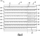
- FIG. 6 schematically illustrates selected features of another example embodiment.
- a liquid electrolyte fuel cell 10 is schematically represented in FIG. 1 . Components of an individual cell are illustrated in FIG. 1 . Those skilled in the art understand how a stack of such cells are assembled into a fuel cell stack assembly.
- the fuel cell 10 includes a cathode flow plate 12 that is configured for directing an oxidant reactant stream flow through the fuel cell 10 through a plurality of oxidant flow channels 14 that are established or defined within the cathode flow plate 12 .
- a cathode substrate layer is situated adjacent the cathode flow plate 12 .
- a cathode catalyst layer 22 is situated adjacent the cathode substrate layer 16 .
- An electrolyte layer 24 is situated adjacent the cathode catalyst layer 22 .
- the electrolyte layer 24 in this example is a liquid electrolyte retaining matrix.
- Liquid electrolyte is schematically represented at 30 in FIG. 1 .
- the liquid electrolyte comprises phosphoric acid.
- An anode catalyst layer 32 is situated adjacent the electrolyte layer 24 on an opposite side from the cathode catalyst layer 22 .
- An anode substrate layer 34 is situated adjacent the anode catalyst layer 32 .
- An anode flow plate 40 includes a plurality of fuel flow channels 42 .
- the anode flow plate 40 is situated adjacent the anode substrate layer 34 .
- the fuel flow channels 42 are configured for directing a flow of fluid reactant into pores of the anode substrate layer 34 so that fuel reaches the anode catalyst layer 32 .
- the cathode substrate layer 16 includes an edge seal 46 and the anode substrate layer 34 includes an edge seal 50 .
- the edge seals 46 and 50 also prevent undesirable movement of a liquid electrolyte or liquid byproducts out of the perimeter of the fuel cell 10 .
- Such edge seals are generally known.
- FIG. 2 schematically illustrates selected portions of a fuel cell stack assembly 60 .
- Coolers 62 are configured for directing a cooling fluid within the assembly 60 in a known manner for managing the temperature of the individual cells of the assembly.
- FIG. 2 For simplicity of illustration, only the anode flow plates 40 of the individual cells are shown in FIG. 2 .
- each individual cell includes the various components shown in FIG. 1 .
- the fuel cell assembly 60 includes an active portion or region 64 and a condensation zone 66 .
- the active region or portion 64 is where the electrochemical reaction takes place for generating electricity.
- the condensation zone 66 may be considered an inactive portion or section of each individual cell.
- anode flow plates 40 there are eight anode flow plates 40 between two coolers 62 .
- the flow plates 40 A, 40 B, 40 G and 40 H are closer to the coolers 62 than the flow plates 40 C, 40 D, 40 E and 40 F. Given their respective proximity to the coolers 62 , the different flow plates will experience different temperatures during fuel cell assembly operation.
- the anode flow plates 40 in the illustrated embodiment include different flow capacities within the condensation zone 66 depending on the proximity of the flow plate to a cooler.
- a first one of the anode flow plates 40 A has a first flow capacity through the fuel flow channels 42 ′ in the condensation zone 66 .
- a second one of the anode flow plates 40 C has a second flow capacity through the fuel flow channels 42 ′′ in the condensation zone 66 .
- Having different flow capacities through the fuel flow channels 42 ′ and 42 ′′ reduces or minimizes the acid loss rate in the cells that tend to be hotter.
- the different flow capacities in the respective flow channels 42 ′ and 42 ′′ within the condensation zone 66 also reduces or minimizes a liquid electrolyte flooding the anode flow plates 40 of the cells having a lower temperature than others of the cells.
- the illustrated example embodiment includes a first cross-sectional area of the flow channels 42 ′ in the first one of the anode flow plates 40 A.
- the flow channels 42 ′′ in the second one of the flow plates 40 C have a second cross-sectional area.
- the first cross-sectional area of the flow channels 42 ′ is smaller than the second cross-sectional area of the flow channels 42 ′′. Having a smaller cross-sectional area restricts the amount of fuel flow through the flow channels 42 ′ compared to the flow channels 42 ′′.
- the different cross-sectional areas are realized by having a first depth of the flow channels 42 ′ compared to a second, larger depth of the flow channels 42 ′′.
- the width of the respective flow channels 42 ′ and 42 ′′ is approximately the same in the example of FIG. 2 .
- FIG. 3 schematically illustrates another configuration in which the flow channels 42 ′ of the first one of the anode flow plates 40 A have a smaller width, which is a horizontal dimension in the drawing, compared to the width of the flow channels 42 ′′ of the second one of the anode flow plates 40 C in the condensation zone 66 .
- the depth of the respective channels 42 ′ and 42 ′′ in this example is approximately the same.
- FIG. 4 schematically illustrates another configuration in which there are fewer flow channels 42 ′ compared to the flow channels 42 ′′. Having fewer channels allows less fuel flow through the channels 42 ′ in the condensation zone 66 compared to the amount of fuel that is able to flow through the channels 42 ′′ in the condensation zone 66 . Realizing a smaller number of channels for one of the anode flow plates compared to another may be accomplished by establishing fewer channels in the portion of the flow plate 40 that will be situated in the condensation zone 66 . In another example embodiment, a complete or partial blockage is situated for effectively preventing flow through a selected number of the channels on a portion of the flow plate 40 that will be situated in the condensation zone 66 .
- FIG. 4 also includes a different cross-sectional area for the flow channels 42 ′ compared to the flow channels 42 ′′.
- FIG. 5 schematically illustrates a feature of another example embodiment.
- the flow channels 42 ′ have a rougher or more varied surface texture schematically shown at 70 compared to a smoother or more uniform surface texture 72 within the flow channels 42 ′′.
- a more course or rougher texture within a flow channel tends to introduce more turbulence which tends to reduce fuel flow through such a channel.
- FIG. 6 illustrates another embodiment in which the flow capacity of the flow channels 42 in the condensation zone 66 progressively vary depending on the distance between a cooler and the respective anode flow plate 40 .
- the flow plates 40 A and 40 H are the closest to the coolers 62 and their flow channels 42 A and 42 H have the smallest flow capacity in the condensation zone 66 .
- the flow plates 40 B and 40 G are the next closest and their respective flow channels 42 B and 42 G have a greater flow capacity than the flow channels 42 A and 42 H.
- the flow channels 42 C and 42 F have a greater flow capacity than the flow channels 42 B and 42 G but a smaller flow capacity than the flow channels 42 D and 42 E.
- FIG. 6 different flow channel depths provide or establish the different flow capacities.
- Other embodiments have progressively varying flow capacities that are established or defined by other features, such as those shown in the other drawings and described above.
- the different flow capacities in the different anode flow plates depending on their proximity to a cooler 62 reverses the process that would otherwise occur because of the different temperatures of the cells. Without the different flow capacities, liquid electrolyte carried by fuel flowing through the active region 64 , which may be referred to as the second pass of the respective flow plates, is lower in the cooler cells compared to that within the corresponding flow channels of the warmer cells further from the coolers 62 .
- the anode flow plates 40 A, 40 B, 40 G and 40 H are considered cooler or lower temperature than the anode flow plates 40 C, 40 D, 40 E and 40 F.
- the number of cells or flow plates that are considered warmer or cooler may vary and those skilled in the art will realize which cells fit into which category depending on their particular fuel cell assembly configuration and cooler placement.
- the flow rate through the cooler cells having the flow channels 42 ′ is lower compared to the flow rate through the channels 42 ′′. More liquid electrolyte may be condensed in the condensation zone 66 in the warmer flow plates (e.g., 40 C, 40 D, 40 E, 40 F in FIG. 2 ) including the flow channels 42 ′′ having a larger flow capacity.
- the lower flow capacity in the condensation zones 66 of the cooler cells including flow channels 42 ′ allows for less acid to be condensed in the third pass of those cells within the condensation zone 66 .
- the different flow capacities reduces the acid or liquid electrolyte loss rate from the higher temperature cells and the potential for acid or liquid electrolyte flooding in the colder cells can also be reduced.
Abstract
Description
Claims (18)
Priority Applications (3)
| Application Number | Priority Date | Filing Date | Title |
|---|---|---|---|
| US15/827,750 US10991957B2 (en) | 2017-11-30 | 2017-11-30 | Fuel cell assembly including multiple flow capacities in a condensation zone |
| PCT/US2018/055390 WO2019108309A1 (en) | 2017-11-30 | 2018-10-11 | Fuel cell assembly including multiple flow capacities in a condensation zone |
| KR1020207018407A KR20200094759A (en) | 2017-11-30 | 2018-10-11 | Fuel cell assembly with multiple flow capacities in the condensation zone |
Applications Claiming Priority (1)
| Application Number | Priority Date | Filing Date | Title |
|---|---|---|---|
| US15/827,750 US10991957B2 (en) | 2017-11-30 | 2017-11-30 | Fuel cell assembly including multiple flow capacities in a condensation zone |
Publications (2)
| Publication Number | Publication Date |
|---|---|
| US20190165386A1 US20190165386A1 (en) | 2019-05-30 |
| US10991957B2 true US10991957B2 (en) | 2021-04-27 |
Family
ID=66634075
Family Applications (1)
| Application Number | Title | Priority Date | Filing Date |
|---|---|---|---|
| US15/827,750 Active 2038-06-20 US10991957B2 (en) | 2017-11-30 | 2017-11-30 | Fuel cell assembly including multiple flow capacities in a condensation zone |
Country Status (3)
| Country | Link |
|---|---|
| US (1) | US10991957B2 (en) |
| KR (1) | KR20200094759A (en) |
| WO (1) | WO2019108309A1 (en) |
Citations (20)
| Publication number | Priority date | Publication date | Assignee | Title |
|---|---|---|---|---|
| US4345008A (en) | 1980-12-24 | 1982-08-17 | United Technologies Corporation | Apparatus for reducing electrolyte loss from an electrochemical cell |
| US4463067A (en) | 1982-09-30 | 1984-07-31 | Engelhard Corporation | Fuel cell and system for supplying electrolyte thereto utilizing cascade feed |
| US5230966A (en) * | 1991-09-26 | 1993-07-27 | Ballard Power Systems Inc. | Coolant flow field plate for electrochemical fuel cells |
| JPH05190186A (en) | 1992-01-17 | 1993-07-30 | Fuji Electric Co Ltd | Lamination type fuel cell |
| US5344722A (en) | 1991-06-28 | 1994-09-06 | Haldor Topsoe A/S | Phosphoric acid fuel cell |
| JPH06251790A (en) | 1993-02-22 | 1994-09-09 | Toshiba Corp | Fuel cell |
| JPH09223505A (en) | 1996-02-16 | 1997-08-26 | Fuji Electric Co Ltd | Phosphoric acid type fuel cell |
| JPH10340733A (en) | 1997-06-05 | 1998-12-22 | Fuji Electric Co Ltd | Fuel cell laminate |
| JPH1116589A (en) | 1997-06-24 | 1999-01-22 | Fuji Electric Co Ltd | Phoshoric acid type fuel cell |
| US20010021470A1 (en) * | 1998-10-08 | 2001-09-13 | Barret May | Fuel cells and fuel cell plates |
| JP2003157887A (en) | 2001-11-21 | 2003-05-30 | Fuji Electric Co Ltd | Solid high polymer fuel cell |
| US20050003257A1 (en) * | 2003-07-02 | 2005-01-06 | Peter Willimowski | Gas control and operation method of a fuel cell system for water and gas distribution |
| US20050238943A1 (en) | 2004-04-27 | 2005-10-27 | Matsushita Electric Industrial Co., Ltd. | Fuel cell stack |
| US20070172709A1 (en) * | 2006-01-25 | 2007-07-26 | Canon Kabushiki Kaisha | Fuel cell system |
| WO2008079126A1 (en) | 2006-12-22 | 2008-07-03 | Utc Power Corporation | Liquid electrolyte fuel cell having high permeability wicking to return condensed electrolyte |
| US20090025566A1 (en) * | 2007-07-26 | 2009-01-29 | Youngjin Son | Condensed water discharging apparatus for fuel cell system |
| US7718295B2 (en) * | 2000-05-01 | 2010-05-18 | Delphi Technologies, Inc. | Method for preparing an interconnect |
| US20120028156A1 (en) | 2010-07-30 | 2012-02-02 | Samsung Electronics Co., Ltd. | Stack having uniform temperature distribution and method of operating the same |
| WO2013126075A1 (en) | 2012-02-24 | 2013-08-29 | Utc Power Corporation | Avoiding fuel starvation of anode end fuel cell |
| US20140065508A1 (en) * | 2012-08-29 | 2014-03-06 | Bloom Energy Corporation | Interconnect for fuel cell stack |
Family Cites Families (1)
| Publication number | Priority date | Publication date | Assignee | Title |
|---|---|---|---|---|
| WO2008019503A1 (en) * | 2006-08-18 | 2008-02-21 | Hyteon Inc. | Method for operating a fuel cell and a fuel cell stack |
-
2017
- 2017-11-30 US US15/827,750 patent/US10991957B2/en active Active
-
2018
- 2018-10-11 WO PCT/US2018/055390 patent/WO2019108309A1/en active Application Filing
- 2018-10-11 KR KR1020207018407A patent/KR20200094759A/en not_active Application Discontinuation
Patent Citations (20)
| Publication number | Priority date | Publication date | Assignee | Title |
|---|---|---|---|---|
| US4345008A (en) | 1980-12-24 | 1982-08-17 | United Technologies Corporation | Apparatus for reducing electrolyte loss from an electrochemical cell |
| US4463067A (en) | 1982-09-30 | 1984-07-31 | Engelhard Corporation | Fuel cell and system for supplying electrolyte thereto utilizing cascade feed |
| US5344722A (en) | 1991-06-28 | 1994-09-06 | Haldor Topsoe A/S | Phosphoric acid fuel cell |
| US5230966A (en) * | 1991-09-26 | 1993-07-27 | Ballard Power Systems Inc. | Coolant flow field plate for electrochemical fuel cells |
| JPH05190186A (en) | 1992-01-17 | 1993-07-30 | Fuji Electric Co Ltd | Lamination type fuel cell |
| JPH06251790A (en) | 1993-02-22 | 1994-09-09 | Toshiba Corp | Fuel cell |
| JPH09223505A (en) | 1996-02-16 | 1997-08-26 | Fuji Electric Co Ltd | Phosphoric acid type fuel cell |
| JPH10340733A (en) | 1997-06-05 | 1998-12-22 | Fuji Electric Co Ltd | Fuel cell laminate |
| JPH1116589A (en) | 1997-06-24 | 1999-01-22 | Fuji Electric Co Ltd | Phoshoric acid type fuel cell |
| US20010021470A1 (en) * | 1998-10-08 | 2001-09-13 | Barret May | Fuel cells and fuel cell plates |
| US7718295B2 (en) * | 2000-05-01 | 2010-05-18 | Delphi Technologies, Inc. | Method for preparing an interconnect |
| JP2003157887A (en) | 2001-11-21 | 2003-05-30 | Fuji Electric Co Ltd | Solid high polymer fuel cell |
| US20050003257A1 (en) * | 2003-07-02 | 2005-01-06 | Peter Willimowski | Gas control and operation method of a fuel cell system for water and gas distribution |
| US20050238943A1 (en) | 2004-04-27 | 2005-10-27 | Matsushita Electric Industrial Co., Ltd. | Fuel cell stack |
| US20070172709A1 (en) * | 2006-01-25 | 2007-07-26 | Canon Kabushiki Kaisha | Fuel cell system |
| WO2008079126A1 (en) | 2006-12-22 | 2008-07-03 | Utc Power Corporation | Liquid electrolyte fuel cell having high permeability wicking to return condensed electrolyte |
| US20090025566A1 (en) * | 2007-07-26 | 2009-01-29 | Youngjin Son | Condensed water discharging apparatus for fuel cell system |
| US20120028156A1 (en) | 2010-07-30 | 2012-02-02 | Samsung Electronics Co., Ltd. | Stack having uniform temperature distribution and method of operating the same |
| WO2013126075A1 (en) | 2012-02-24 | 2013-08-29 | Utc Power Corporation | Avoiding fuel starvation of anode end fuel cell |
| US20140065508A1 (en) * | 2012-08-29 | 2014-03-06 | Bloom Energy Corporation | Interconnect for fuel cell stack |
Non-Patent Citations (2)
| Title |
|---|
| International Search Report and Written Opinion of the International Searching Authority for International application No. PCT/US2018/055386 dated Jan. 29, 2019. |
| International Search Report and Written Opinion of the International Searching Authority for International application No. PCT/US2018/055390 dated Jan. 29, 2019. |
Also Published As
| Publication number | Publication date |
|---|---|
| KR20200094759A (en) | 2020-08-07 |
| WO2019108309A1 (en) | 2019-06-06 |
| US20190165386A1 (en) | 2019-05-30 |
Similar Documents
| Publication | Publication Date | Title |
|---|---|---|
| US10468691B2 (en) | Bipolar plates for use in conduction-cooled electrochemical cells | |
| EP2865040B1 (en) | Flow field plate for a fuel cell | |
| US9853300B2 (en) | Bipolar plate structure for fuel cell | |
| US9608282B2 (en) | Fuel cell having perforated flow field | |
| US9748583B2 (en) | Flow field plate for improved coolant flow | |
| JP2008525991A (en) | Fuel cell with reduced number of cooling plates by varying oxidant flow channel depth | |
| KR20140075465A (en) | Fuel cell stack having cooling plate for improving temperature distribution | |
| CN103915631A (en) | Air-cooled integrated bipolar plate for fuel cells | |
| US11133519B2 (en) | Fuel cell assembly including varied flow resistance | |
| US10991957B2 (en) | Fuel cell assembly including multiple flow capacities in a condensation zone | |
| CN106207235A (en) | There is the fuel cell of the reactant distribution of improvement | |
| CN218731068U (en) | Bipolar plate for fuel cell | |
| CN107667445B (en) | Separator and fuel cell stack including the same | |
| JP2008293835A (en) | Fuel cell | |
| EP3054514B1 (en) | Separator plate unit for a fuel cell and fuel cell comprising the same with enhanced performance | |
| KR20150056206A (en) | Bipolar plate for fuel cell and fuel cell using the same | |
| CN107592945B (en) | Cathode plate for a bipolar element and method for operating such a cathode plate | |
| EP3123546A1 (en) | Relief design for fuel cell plates | |
| CN218004919U (en) | Polar plate of fuel cell and fuel cell | |
| KR101990280B1 (en) | Separator and Fuel cell stack comprising the same | |
| KR20150079569A (en) | Fuel cell component having selected cooling capacity distribution |
Legal Events
| Date | Code | Title | Description |
|---|---|---|---|
| FEPP | Fee payment procedure |
Free format text: ENTITY STATUS SET TO UNDISCOUNTED (ORIGINAL EVENT CODE: BIG.); ENTITY STATUS OF PATENT OWNER: LARGE ENTITY |
|
| AS | Assignment |
Owner name: DOOSAN FUEL CELL AMERICA, INC., CONNECTICUT Free format text: ASSIGNMENT OF ASSIGNORS INTEREST;ASSIGNORS:GONG, KE;OSEPOWICZ, NICHOLAS EDWARD;LIVAICH, ERIC;AND OTHERS;SIGNING DATES FROM 20170821 TO 20170905;REEL/FRAME:044680/0840 |
|
| STPP | Information on status: patent application and granting procedure in general |
Free format text: DOCKETED NEW CASE - READY FOR EXAMINATION |
|
| STPP | Information on status: patent application and granting procedure in general |
Free format text: NON FINAL ACTION MAILED |
|
| STPP | Information on status: patent application and granting procedure in general |
Free format text: NON FINAL ACTION MAILED |
|
| STPP | Information on status: patent application and granting procedure in general |
Free format text: RESPONSE TO NON-FINAL OFFICE ACTION ENTERED AND FORWARDED TO EXAMINER |
|
| STPP | Information on status: patent application and granting procedure in general |
Free format text: FINAL REJECTION MAILED |
|
| STPP | Information on status: patent application and granting procedure in general |
Free format text: NON FINAL ACTION MAILED |
|
| STPP | Information on status: patent application and granting procedure in general |
Free format text: NOTICE OF ALLOWANCE MAILED -- APPLICATION RECEIVED IN OFFICE OF PUBLICATIONS |
|
| STPP | Information on status: patent application and granting procedure in general |
Free format text: PUBLICATIONS -- ISSUE FEE PAYMENT RECEIVED |
|
| STPP | Information on status: patent application and granting procedure in general |
Free format text: PUBLICATIONS -- ISSUE FEE PAYMENT VERIFIED |
|
| STCF | Information on status: patent grant |
Free format text: PATENTED CASE |
|
| AS | Assignment |
Owner name: HYAXIOM, INC., CONNECTICUT Free format text: CHANGE OF NAME;ASSIGNOR:DOOSAN FUEL CELL AMERICA, INC.;REEL/FRAME:059747/0284 Effective date: 20220224 |