US10991105B2 - Image processing device - Google Patents
Image processing device Download PDFInfo
- Publication number
- US10991105B2 US10991105B2 US16/565,711 US201916565711A US10991105B2 US 10991105 B2 US10991105 B2 US 10991105B2 US 201916565711 A US201916565711 A US 201916565711A US 10991105 B2 US10991105 B2 US 10991105B2
- Authority
- US
- United States
- Prior art keywords
- image
- unit
- point
- motion vector
- imaging
- Prior art date
- Legal status (The legal status is an assumption and is not a legal conclusion. Google has not performed a legal analysis and makes no representation as to the accuracy of the status listed.)
- Active, expires
Links
- 238000012545 processing Methods 0.000 title claims abstract description 269
- 238000003384 imaging method Methods 0.000 claims abstract description 216
- 230000003287 optical effect Effects 0.000 claims abstract description 139
- 239000013598 vector Substances 0.000 claims description 214
- 238000004364 calculation method Methods 0.000 claims description 109
- 230000008859 change Effects 0.000 claims description 33
- 238000001514 detection method Methods 0.000 description 51
- 238000000034 method Methods 0.000 description 37
- 238000005096 rolling process Methods 0.000 description 33
- 230000006870 function Effects 0.000 description 30
- 238000010586 diagram Methods 0.000 description 18
- 238000011156 evaluation Methods 0.000 description 12
- 238000007689 inspection Methods 0.000 description 10
- 230000007547 defect Effects 0.000 description 9
- 238000006073 displacement reaction Methods 0.000 description 9
- 230000008569 process Effects 0.000 description 9
- 230000010354 integration Effects 0.000 description 7
- 230000036544 posture Effects 0.000 description 5
- 230000009466 transformation Effects 0.000 description 5
- 230000008034 disappearance Effects 0.000 description 4
- 230000011218 segmentation Effects 0.000 description 4
- 230000000087 stabilizing effect Effects 0.000 description 4
- 238000004891 communication Methods 0.000 description 3
- 238000012937 correction Methods 0.000 description 3
- 239000000284 extract Substances 0.000 description 3
- 230000002542 deteriorative effect Effects 0.000 description 2
- 230000000694 effects Effects 0.000 description 2
- 239000011159 matrix material Substances 0.000 description 2
- 238000012986 modification Methods 0.000 description 2
- 230000004048 modification Effects 0.000 description 2
- 238000012544 monitoring process Methods 0.000 description 2
- 238000010422 painting Methods 0.000 description 2
- 238000012567 pattern recognition method Methods 0.000 description 2
- 229920006395 saturated elastomer Polymers 0.000 description 2
- 238000001228 spectrum Methods 0.000 description 2
- 238000013459 approach Methods 0.000 description 1
- 230000008901 benefit Effects 0.000 description 1
- 230000007423 decrease Effects 0.000 description 1
- 230000006866 deterioration Effects 0.000 description 1
- 230000004069 differentiation Effects 0.000 description 1
- 230000009189 diving Effects 0.000 description 1
- 238000000605 extraction Methods 0.000 description 1
- 230000009191 jumping Effects 0.000 description 1
- 238000002372 labelling Methods 0.000 description 1
- 238000013507 mapping Methods 0.000 description 1
- 239000000463 material Substances 0.000 description 1
- 238000005259 measurement Methods 0.000 description 1
- 230000006641 stabilisation Effects 0.000 description 1
- 238000011105 stabilization Methods 0.000 description 1
- 230000002123 temporal effect Effects 0.000 description 1
- 238000011179 visual inspection Methods 0.000 description 1
Images


Classifications
-
- G—PHYSICS
- G06—COMPUTING; CALCULATING OR COUNTING
- G06T—IMAGE DATA PROCESSING OR GENERATION, IN GENERAL
- G06T7/00—Image analysis
- G06T7/20—Analysis of motion
- G06T7/246—Analysis of motion using feature-based methods, e.g. the tracking of corners or segments
-
- G—PHYSICS
- G06—COMPUTING; CALCULATING OR COUNTING
- G06T—IMAGE DATA PROCESSING OR GENERATION, IN GENERAL
- G06T7/00—Image analysis
- G06T7/20—Analysis of motion
- G06T7/246—Analysis of motion using feature-based methods, e.g. the tracking of corners or segments
- G06T7/248—Analysis of motion using feature-based methods, e.g. the tracking of corners or segments involving reference images or patches
-
- G06K9/00805—
-
- G06T5/003—
-
- G—PHYSICS
- G06—COMPUTING; CALCULATING OR COUNTING
- G06T—IMAGE DATA PROCESSING OR GENERATION, IN GENERAL
- G06T5/00—Image enhancement or restoration
- G06T5/50—Image enhancement or restoration using two or more images, e.g. averaging or subtraction
-
- G—PHYSICS
- G06—COMPUTING; CALCULATING OR COUNTING
- G06T—IMAGE DATA PROCESSING OR GENERATION, IN GENERAL
- G06T5/00—Image enhancement or restoration
- G06T5/73—Deblurring; Sharpening
-
- G—PHYSICS
- G06—COMPUTING; CALCULATING OR COUNTING
- G06T—IMAGE DATA PROCESSING OR GENERATION, IN GENERAL
- G06T7/00—Image analysis
- G06T7/20—Analysis of motion
- G06T7/269—Analysis of motion using gradient-based methods
-
- G—PHYSICS
- G06—COMPUTING; CALCULATING OR COUNTING
- G06T—IMAGE DATA PROCESSING OR GENERATION, IN GENERAL
- G06T7/00—Image analysis
- G06T7/30—Determination of transform parameters for the alignment of images, i.e. image registration
- G06T7/33—Determination of transform parameters for the alignment of images, i.e. image registration using feature-based methods
- G06T7/337—Determination of transform parameters for the alignment of images, i.e. image registration using feature-based methods involving reference images or patches
-
- G—PHYSICS
- G06—COMPUTING; CALCULATING OR COUNTING
- G06T—IMAGE DATA PROCESSING OR GENERATION, IN GENERAL
- G06T7/00—Image analysis
- G06T7/30—Determination of transform parameters for the alignment of images, i.e. image registration
- G06T7/38—Registration of image sequences
-
- G—PHYSICS
- G06—COMPUTING; CALCULATING OR COUNTING
- G06V—IMAGE OR VIDEO RECOGNITION OR UNDERSTANDING
- G06V20/00—Scenes; Scene-specific elements
- G06V20/50—Context or environment of the image
- G06V20/56—Context or environment of the image exterior to a vehicle by using sensors mounted on the vehicle
- G06V20/58—Recognition of moving objects or obstacles, e.g. vehicles or pedestrians; Recognition of traffic objects, e.g. traffic signs, traffic lights or roads
-
- G06K2209/21—
-
- G—PHYSICS
- G06—COMPUTING; CALCULATING OR COUNTING
- G06T—IMAGE DATA PROCESSING OR GENERATION, IN GENERAL
- G06T2207/00—Indexing scheme for image analysis or image enhancement
- G06T2207/10—Image acquisition modality
- G06T2207/10016—Video; Image sequence
-
- G—PHYSICS
- G06—COMPUTING; CALCULATING OR COUNTING
- G06T—IMAGE DATA PROCESSING OR GENERATION, IN GENERAL
- G06T2207/00—Indexing scheme for image analysis or image enhancement
- G06T2207/20—Special algorithmic details
- G06T2207/20172—Image enhancement details
- G06T2207/20201—Motion blur correction
-
- G—PHYSICS
- G06—COMPUTING; CALCULATING OR COUNTING
- G06T—IMAGE DATA PROCESSING OR GENERATION, IN GENERAL
- G06T2207/00—Indexing scheme for image analysis or image enhancement
- G06T2207/30—Subject of image; Context of image processing
- G06T2207/30248—Vehicle exterior or interior
- G06T2207/30252—Vehicle exterior; Vicinity of vehicle
-
- G—PHYSICS
- G06—COMPUTING; CALCULATING OR COUNTING
- G06V—IMAGE OR VIDEO RECOGNITION OR UNDERSTANDING
- G06V2201/00—Indexing scheme relating to image or video recognition or understanding
- G06V2201/07—Target detection
Definitions
- the present disclosure relates to an image processing device.
- Japanese Unexamined Patent Publication No. 2006-170961 discloses a device for processing an image obtained by an imaging unit such as an in-vehicle camera.
- the device detects a center position (a vanishing point) of displacement in the image displaced by a vibration of the vehicle.
- the device monitors the vanishing point to calculate an amount of displacement of the image caused by the vibration of the vehicle in the captured image.
- the device performs a frequency analysis (Fourier transform) based on a history of the coordinates of the detection area, and creates a graph illustrating a relationship between a vibration frequency and a power spectrum intensity indicating an intensity of each frequency in the detection area.
- a frequency analysis Frier transform
- a predetermined frequency band including the above-described frequency is extracted using a band pass filter.
- inverse Fourier transform is performed on the extracted predetermined frequency band, and then, a temporal change in the amount of displacement in the predetermined frequency band within the detection area can be obtained.
- An image (balanced image) captured at a time when the amount of displacement is 0 is an image captured when the camera is not receiving an influence of the vibration which is normally occurring in the vehicle.
- An optical flow is calculated based on a longitudinal motion of lateral edges of a plurality of balanced images.
- an image velocity and a velocity direction in the longitudinal direction are calculated in the balanced image.
- an image velocity can be obtained, which is a result of removing the image velocity generated by the normal vibration of the vehicle.
- the coordinate axes are set in the horizontal center of the image velocity corrected as described above, coordinates having the lowest movement velocity on the coordinate axis are set as the coordinates of the vanishing point. Using this vanishing point as a reference, a blur correction between the images can be performed.
- the recognition accuracy can be improved by using a plurality of images.
- there is a motion in the imaging unit caused by the vibration of the vehicle or the like since a coordinate variation of the image occurs, it is difficult to associate the recognition targets in each image with each other.
- Japanese Unexamined Patent Publication No. 2006-170961 discloses a device that associates the recognition targets in each image with each other using the estimated vanishing point as described above.
- the recognition targets cannot be sufficiently associated in each image with each other.
- the device disclosed in Japanese Unexamined Patent Publication No. 2006-170961 may not be able to correctly detect the balanced image or the image velocity of the balanced image.
- the image velocity of the balanced image is the average of the image velocity at the time when the amount of displacement becomes 0, there is a problem in that the device disclosed in Japanese Unexamined Patent Publication No. 2006-170961 may not be able to correctly correct the image velocity of the image of another time point. Furthermore, when the vehicle travels along a curved road, it is difficult for the device disclosed in Japanese Unexamined Patent Publication No. 2006-170961 to detect the vanishing point, and there is a problem in that the amount of displacement of the image cannot be correctly obtained.
- the present disclosure provides an image processing device that can associate the recognition targets in each image with each other even when there is a motion in the imaging unit.
- an image processing device configured to set a reference point on an image obtained by an imaging unit moving in an optical axis direction.
- the device includes: a storage unit; an initial setting unit configured to store a position of an optical axis neighborhood point in a first image obtained by the imaging unit in the storage unit as an initial position of a specific point in the first image in association with image features of a surrounding area of the optical axis neighborhood point; a search unit configured to search for a corresponding point of the specific point in a second image obtained by the imaging unit based on the image features stored in the storage unit; and an output unit configured to output a position of the corresponding point in the second image as a position of the reference point in the second image.
- the position of the optical axis neighborhood point in the first image obtained by the imaging unit moving in the optical axis direction is set as the initial position of the specific point.
- the optical axis neighborhood point is a point where the motion vector caused by the variation of the rolling angle and the translational movement is small.
- the position of the optical axis neighborhood point is stored as a specific point in association with the image features of the surrounding area of the optical axis neighborhood point.
- the first image and the second image are associated with each other.
- the corresponding point in the second image corresponding to the specific point in the first image is searched based on the image features of the surrounding area of the optical axis neighborhood point.
- the searched corresponding point is the reference point in the second image.
- the reference point is a reference position when associating the first image with the second image, and for example, is a reference position of the relative position coordinates in the second image.
- the specific point is a reference of the relative position coordinates.
- the image processing device may further include a motion vector calculation unit configured to calculate a relative motion vector between a pixel and the reference point in each pixel of the second image.
- the difference between the output position of the reference point and the position of the specific point stored in the storage unit is a motion vector from a time point when the specific point is stored in the storage unit to a time point when the second image is generated, and is caused by the variations of the pitch angle and yaw angle. Therefore, the image processing device can compensate the coordinate variation caused by the variations of the pitch angle and yaw angle by calculating the relative motion vector, which is the relative motion between the pixel and the reference point.
- an image processing device configured to estimate a rotational movement of an imaging unit moving in an optical axis direction, based on an image obtained by the imaging unit.
- the device includes: a setting unit configured to set an optical axis neighborhood point in the image as a specific point; a first estimation unit configured to estimate a rotational velocity component of at least one axial rotation of a first axis and a second axis parallel to an imaging plane of the imaging unit, orthogonal to each other among the rotational velocity components, based on a motion vector in the surrounding area of the specific point; and a second estimation unit configured to estimate a rotational velocity component of an axial rotation of a third axis, which is a straight line connecting the specific point and an optical center of the imaging unit, based on the rotational velocity component estimated by the first estimation unit, a constraint condition assuming that a brightness value of the imaging target does not change due to a relative movement between the imaging unit and the imaging target, and a relationship between the movement of the imaging
- the position of the optical axis neighborhood point in the image obtained by the imaging unit moving in the optical axis direction is set as the position of the specific point.
- the rotational velocity component of the axial rotation of at least one of the first axis and the second axis parallel to each other and orthogonal to the imaging plane of the imaging unit among the rotational velocity components is estimated based on the motion vector in the surrounding area of the specific point.
- the rotational velocity component of the axial rotation of the third axis which is a straight line connecting the specific point and the optical center of the imaging unit is estimated based on the rotational velocity component estimated by first estimation unit, the constraint condition assuming that the brightness value of the imaging target does not change due to the relative movement of the imaging unit and the imaging target, and the relation between movement of the imaging unit and the motion vector of each pixel on the image. If the rotational velocity components of two or three axial rotations are estimated at a time, the equation for the estimation will have a plurality of unknowns.
- the rotational velocity component of the axial rotation of the third axis has a considerably smaller value than the rotational velocity component of the first axis and the second axis.
- the estimation is driven by the large value component, and thus, the error of the small value component increases.
- the device divides the estimation into two, such as the estimation of the rotational velocity component of the axial rotation of at least one of the first axis and the second axis and the estimation of the rotational velocity component of the axial rotation of the third axis. Therefore, the device can improve the estimation accuracy of the rotational velocity component of the axial rotation of the third axis compared to a case where the rotational velocity components of two or three axial rotations are estimated at a time.
- an image processing device configured to calculate an arrival time until the imaging unit moving in an optical axis direction arrives at an imaging target, based on an image obtained by the imaging unit.
- the device includes: a rotation estimation unit configured to estimate a rotational velocity component relating to at least one axis of a movement of the imaging unit itself; and an arrival time calculation unit configured to calculate an arrival time in which the rotational velocity component relating to at least one axis is compensated, based on the rotational velocity component estimated by the rotation estimation unit, a constraint condition assuming that a brightness value of the imaging target does not change due to a relative movement between the imaging unit and the imaging target, and a relationship between the movement of the imaging unit and the motion vector of each pixel on the image.
- the main movement of the imaging unit is the translational movement component of the traveling direction.
- the movement of the imaging unit also includes the rotational movement component such as the pitch angle velocity due to the unevenness of the road surface and the yaw angle velocity due to turning. Therefore, when the arrival time is calculated using only the translational movement component, the accuracy of the calculated arrival time may deteriorate.
- the rotational velocity component relating to at least one axis of the movement of the imaging unit itself is estimated.
- the arrival time in which the rotational velocity component relating to at least one axis is compensated is calculated based on the estimated rotational velocity component, the constraint condition assuming that the brightness value of the imaging target does not change due to the relative movement of the imaging unit and the imaging target, and the relation between the motion of the imaging unit and the motion vector of each pixel on the image.
- the device can estimate the arrival (collision) time with high accuracy even when the imaging unit vibrates up and down or makes the turning movement.
- the arrival time is directly calculated without estimating the motion vector, the device can realize the estimation of the arrival time with a simple configuration.
- an image processing device configured to calculate a motion vector in which a motion of an imaging unit moving in an optical axis direction is compensated based on an image obtained by the imaging unit.
- the device includes: a rotation estimation unit configured to estimate a rotational velocity component relating to at least one axis of a movement of the imaging unit itself, a normalized translational velocity estimation unit configured to estimate a translational velocity that is normalized by a distance relating to at least one axis, based on the rotational velocity component estimated by the rotation estimation unit, a constraint condition assuming that a brightness value of the imaging target does not change due to a relative movement between the imaging unit and the imaging target, and a relationship between the movement of the imaging unit and the motion vector of each pixel on the image, and an unusual motion vector calculation unit configured to calculate a motion vector excluding a motion of a pixel caused by a motion of the imaging unit, based on the rotational velocity component estimated by the rotation estimation unit, the translational velocity estimated by the
- the motion vector (optical flow) on the image can be defined based on the relative rotational movement between the imaging unit and the imaging target, the distance normalized relative translational movement between the imaging unit and the imaging target, and the coordinates of each pixel.
- the distance normalized relative translational movement is a value obtained by dividing the relative translational velocity between the imaging unit and the imaging target by the distance from the point in the imaging target corresponding to each pixel to the imaging unit. Therefore, when the imaging unit is moving and the imaging target is stationary, the motion vector can be defined based on the rotational movement of the imaging unit and velocity of the distance normalized relative translational movement of the imaging unit.
- the imaging target includes a moving object
- a motion vector is observed, in which the component of the motion of the imaging target is added to the defined motion vector.
- the device calculates a motion vector in which motion of the pixel due to the motion of the imaging unit is excluded, based on the relationship between motion of the imaging unit and the motion vector of each pixel on the image. Therefore, only the motion vector caused by the motion of the imaging target, that is, the motion vector of the imaging target that is moving can be extracted.
- an image processing device configured to set a reference point in a second image obtained by an imaging unit using a specific point in a first image obtained by a fixed imaging unit.
- the device includes: a storage unit; a motion vector calculation unit configured to calculate a motion vector based on the first image; an area setting unit configured to set an area having a uniform motion vector in the first image based on the motion vector calculated by the motion vector calculation unit; an initial setting unit configured to store a position of the point included in the area in the storage unit as the initial position of the specific point in association with an image feature of a surrounding area of the specific point; a search unit configured to search for a corresponding point of the specific point in the second image based on the image feature stored in the storage unit; and an output unit configured to output the position of the corresponding point in the second image as a position of a reference point in the second image.
- the motion vector is calculated based on the first image obtained by the fixed imaging unit, and the area having the uniform motion vector is set in the first image.
- the position of the point included in the area having uniform motion vector set as the initial position of the specific point.
- the position of the specific point is stored in association with the image features of the surrounding area of the specific point.
- the first image and the second image are associated with each other.
- the corresponding point in the second image corresponding to the specific point in the first image is searched based on the image features of the surrounding area of the specific point.
- the searched corresponding point is the reference point in the second image.
- the reference point is a reference position when associating the first image with the second image, and for example, is a reference position in the relative position coordinates in the second image.
- the feature amount is small and the motion vector is small, it becomes difficult to associate the first image with the second image.
- the device even if the feature amount is small, it is possible to associate the recognition targets in each image with each other by setting the reference point in the second image using a point included in the area having a uniform motion vector.
- an image processing device that can associates the recognition targets in each image with each other, even when there is a motion in the imaging unit.
- FIG. 1 is a functional block diagram of a vehicle including an image processing device in a first embodiment.
- FIG. 2 is a flowchart illustrating an example of an operation by the image processing device in FIG. 1 .
- FIG. 3 is a functional block diagram of a vehicle including an image processing device in a second embodiment.
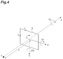
- FIG. 4 is a diagram illustrating a definition of a camera coordinate system.
- FIG. 5 is a flowchart illustrating an example of an operation by the image processing device in FIG. 3 .
- FIG. 6 is a functional block diagram of a vehicle including an image processing device in a third embodiment.
- FIG. 7 is a flowchart illustrating an example of an operation by the image processing device in FIG. 6 .
- FIG. 8 is a functional block diagram of a vehicle including an image processing device in a fourth embodiment.
- FIG. 9 is a flowchart illustrating an example of an operation by the image processing device in FIG. 8 .
- FIG. 10 is a functional block diagram of a vehicle including an image processing device in a fifth embodiment.
- FIG. 11 is a diagram for explaining a geometric definition of a road surface candidate area.
- FIG. 12 is a flowchart illustrating an example of an operation by the image processing device in FIG. 10 .
- FIG. 13 is a schematic diagram of an inspection system in a sixth embodiment.
- FIG. 14A is an image captured when the workpiece vibrates to the left.
- FIG. 14B is an image captured when the workpiece positions at the center.
- FIG. 14C is an image captured when the workpiece vibrates to the right.
- FIG. 15 is a functional block diagram of an image processing device in a sixth embodiment.
- FIG. 16 is a flowchart illustrating an example of an operation by the image processing device in FIG. 15 .
- FIG. 1 is a functional block diagram of a vehicle including an image processing device in a first embodiment.
- an image processing device 1 is mounted on a vehicle 2 .
- the vehicle 2 includes a camera 200 (an example of an imaging unit).
- the camera 200 looks forward in the traveling direction of the vehicle 2 . Therefore, an imaging direction (an optical axis direction) of the camera 200 substantially coincides with the traveling direction of the vehicle 2 .
- the camera 200 is an imaging unit that moves approximately in the optical axis direction.
- the camera 200 is calibrated such that a pinhole camera model can be adapted. That is, internal parameters of the camera 200 are already well-known and the lens distortion is also corrected.
- the present disclosure discloses a practical technical idea to appropriately reduce the influence of movement of the imaging unit, and implies an effect of correcting the deviation between the traveling direction of the vehicle and the optical axis direction as a matter of course. Therefore, the present disclosure does not require an exact match between the two directions.
- moving in the optical axis direction means “substantially moving in the optical axis direction”.
- the camera 200 is a time correlation image sensor (correlation image sensor (CIS)).
- the CIS is an image sensor that outputs the time correlation between a light intensity signal of each pixel and a reference signal common to all pixels.
- the CIS by using a sine wave signal as the reference signal, an output corresponding to the Fourier transform of the frequency of the sine wave signal can be obtained.
- the CIS outputs an intensity image g 0 that can be acquired by a general image sensor, and outputs a time correlation between the intensity signal of each pixel and the reference signal common to all the pixels as a correlation image g 1 .
- the correlation image g 1 expresses two correlation images with respect to the reference signal, of which phases are different from each other by 90°, as a complex number having a real part and an imaginary part.
- the camera 200 may generate images (frames) configuring a moving picture. In this case, the camera 200 outputs images at a predetermined time interval.
- the camera 200 may be a general image sensor camera that outputs only the intensity image.
- the image processing device 1 is a device that is configured to be capable of communicating with the camera 200 and performs image processing on the image obtained by the camera 200 .
- the image processing device 1 that is, an ECU is an electronic control unit including a calculation unit such as a central processing unit (CPU), a storage unit such as a read only memory (ROM) and a random access memory (RAM), and a communication unit such as controller area network (CAN).
- the ECU is connected to a network that communicates, for example, using a CAN communication circuit.
- the ECU realizes various functions of configuration elements of the image processing device 1 described below by inputting and outputting data by operating the CAN communication circuit based on, for example, a signal output from the CPU, recording the data in the RAM, loading the program recorded in the ROM into the RAM, and executing the program loaded in the RAM.
- the ECU may be configured with a plurality of electronic units.
- the image processing device 1 sets a reference point on the image obtained by the camera 200 moving in the optical axis direction.
- the image on which the reference point is to be set may be the intensity image or the correlation image.
- the reference point is a reference position (a coordinate point) when associating images obtained by the camera 200 with each other.
- the reference point can be any of the reference point among an association between a first intensity image and a second intensity image, an association between a first correlation image and a second correlation image, and an association between a first intensity image and a second correlation image.
- any image obtained by the camera 200 is referred to as a first image
- any image obtained by the camera 200 that is different from the first image will be referred to as a second image.
- the image processing device 1 includes an image acquisition unit 11 , a specific point management unit 12 , and a motion vector calculation unit 20 .
- the image processing device 1 does not necessarily need to include the motion vector calculation unit 20 .
- the image acquisition unit 11 acquires an image from the camera 200 .
- the image acquisition unit 11 acquires the image obtained by the camera 200 via, for example, a network.
- the image acquisition unit 11 acquires a frame of a moving picture at each time as an example.
- the specific point management unit 12 includes an initial setting unit 120 , a search unit 121 , an output unit 122 , and a specific point storage unit 123 (an example of a storage unit).
- the initial setting unit 120 stores a position of an optical axis neighborhood point in the first image obtained by the camera 200 into the specific point storage unit 123 as an initial position of a specific point in the first image, in association with image features of a surrounding area of the optical axis neighborhood point.
- the optical axis neighborhood point is a point on an imaging plane of the camera 200 , which is positioned around an intersection of the optical axis of the camera 200 and the imaging plane of the camera 200 .
- the optical axis neighborhood point may be the intersection of the optical axis of the camera 200 and the imaging plane.
- the initial setting unit 120 obtains the optical axis neighborhood point based on the first image, and stores the optical axis neighborhood point in the specific point storage unit 123 as the initial position of the specific point in the first image.
- the specific point is a coordinate point for determining a reference point.
- the initial setting unit 120 acquires the image features of the surrounding area of the optical axis neighborhood point based on the first image.
- the surrounding area is an area having a predetermined size including the optical axis neighborhood point, and the image features are intensity images and may be feature amounts of edges and corners or the like extracted from the intensity images.
- the initial setting unit 120 stores the optical axis neighborhood point in the specific point storage unit 123 while associating the position of the acquired optical axis neighborhood point on the image with the image features.
- To associate refers to defining a coordinate range of the image features such that the image features are specified when the position of the optical axis neighborhood point on the image is specified.
- the movement of the camera 200 can be divided into translational three components and rotational three components (pitch angle, yaw angle, and rolling angle).
- a coordinate variation of the image caused by the variations of the pitch angle and yaw angle among the rotational three components, that is, a motion vector (optical flow) becomes uniform on the image regardless of a distance between the camera 200 and the imaging target.
- the size of the motion vector on the image caused by the rolling angle variation of the camera 200 differs depending on the position on the image, and depends on the distance from a rotation center of the rolling angle.
- the motion vector on the image caused by the translational movement of the camera 200 depends on the distance between camera 200 and the imaging target, and is larger at a nearer distance and is small as can be ignored at a sufficiently long distance.
- the optical axis neighborhood on the image obtained by the camera 200 moving in the optical axis direction can be considered to be at the sufficiently long distance if there is no obstacle. Therefore, at the optical axis neighborhood, the motion vector caused by the rolling angle variation and the translational movement can be regarded as sufficiently small.
- the initial setting unit 120 can the coordinate points correspond to other, of which the influences of motion vectors caused by the rolling angle variation and translational movement are small.
- the initial setting unit 120 may select a point having the largest amount of information on the image features (spatial information amount) to be associated among the candidates of the optical axis neighborhood point, as an initial position of the specific point. In this case, certainty and processing stability of searching for the corresponding points in the search unit 121 are improved. As an example, the initial setting unit 120 sets the coordinates (x 0 , y 0 ) of the optical axis center at the initial time point as a candidate for specific point coordinates. Then, an integral value of edge intensity around the coordinates (x 0 , y 0 ) of the candidate of the specific point coordinates is calculated by following Formula.
- the initial setting unit 120 sets the coordinates (x 0 , y 0 ) as the specific point, and stores the result in the specific point storage unit 123 in association with the image features of the surrounding area.
- the initial setting unit 120 selects a point having the largest integral value of edge intensity, that is, the largest spatial information amount near the coordinates (x 0 , y 0 ) as a specific point, and stores that point in the specific point storage unit 123 in association with the image features of the surrounding area of that point.
- the initial setting unit 120 may set the specific point outside that area.
- the specific point management unit 12 includes a moving object area detection unit that detects the moving object area.
- the method of detecting the moving object area is not particularly limited.
- the moving object area detection unit can use a labeling method such as Semantic segmentation or a pattern recognition method such as a single shot multibox detector (SSD).
- Semantic segmentation a label is given to each pixel (x, y) to indicate whether the pixel represents a moving object or not using an intensity image g 0 (x, y, t).
- the pattern recognition method such as the SSD, the moving object is detected as a rectangle.
- the moving object area detection unit does not need to give the label to each pixel to indicate whether the pixel represents a moving object or not, but may hold only the coordinates of the left, right, upper and lower ends of the rectangle. In this way, the memory can be used efficiently.
- the initial setting unit 120 selects a candidate of the optical axis neighborhood point existing outside the moving object area as the initial position of the specific point. In this way, in the search unit 121 , it is possible to eliminate the motion component on the captured image caused by the movement of the moving object and obtain the corresponding point.
- the initial setting unit 120 may exclude the image features relating to the moving object area in advance from the image features stored in association with the specific point.
- the search unit 121 searches for the corresponding point of the specific point in the second image obtained by the camera 200 based on the image features of the surrounding area of the specific point stored in the specific point storage unit 123 . Specifically, the search unit 121 obtains (x c (t), y c (t)) which is a position (coordinates) of the specific point at the time point t at which the second image corresponding to the position of the specific point stored in the specific point storage unit is imaged. As an example, the search unit 121 uses the image features of the surrounding area of the specific point as a template, and searches for the corresponding points by template matching.
- the search unit 121 may search for the corresponding points excluding the image features included in the moving object area among the image features of the surrounding area of the specific point stored in the specific point storage unit 123 . For example, when an intensity image is associated with the specific point as the image features, the search unit 121 searches for the corresponding point using the intensity image in which the moving object area is excluded.
- the specific point management unit 12 includes the moving object area detection unit described above. When a moving object area is detected by the moving object area detection unit, the search unit 121 searches for the corresponding point using the intensity image excluding the moving object area.
- the output unit 122 outputs a position of the corresponding point in the second image as a position of the reference point in the second image.
- the output unit 122 may output the reference point in the second image to the storage unit of the image processing device 1 , or may output the reference point in the second image to another configuration element.
- the output reference point is used to associate the recognition targets in each image with each other, or is used to compensate the motion of the camera 200 .
- the difference between the coordinates of the output reference point and the coordinates of the stored specific point is a component caused by the variations of the pitch angle and the yaw angle in the motion vector from the time when the specific point is stored to time of acquiring the second image.
- the initial setting unit 120 may initialize the specific point stored in the specific point storage unit 123 when a predetermined condition is satisfied. For example, when the corresponding point in the second image deviates from the range of the optical axis neighborhood point in the second image, the initial setting unit 120 stores the optical axis neighborhood point in the second image in the specific point storage unit 123 in association with the image features of the surrounding area of that optical axis neighborhood point. In this case, for example, when the vehicle 2 mounted with the camera 200 moves along a curved road, even if the specific point deviates from the optical axis neighborhood, the corresponding point can be set continuously.
- the specific point management unit 12 may include an update unit that updates the specific point stored in the specific point storage unit 123 when a predetermined condition is satisfied.
- the update unit stores the corresponding point of a second frame in the specific point storage unit 123 in association with the image features of the area around that corresponding point. In this case, even when the image features around the specific point change from that of the initial value setting time of the specific point, it is possible to reliably obtain the corresponding point in a third frame.
- the update unit may update the specific point on a frame-by-frame basis, or may update the specific point on a frame-by-frame basis while not updating the specific point in a specific frame.
- the specific point management unit 12 may include an accumulated image generation unit that performs coordinate transformation (position matching) based on the reference point for each frame, and stores an accumulated image in which brightness values from the past to the previous frame are accumulated, in the storage unit.
- the accumulated image is an image in which the motion of the camera 200 is compensated.
- the update unit described above updates the specific point storage unit 123 while associating the position of the specific point with the accumulated image of the surrounding area. In the accumulated image, the information for the longer time relating to the image features of the surrounding area of the specific point is reflected.
- the accumulated image generation unit when a distance between the corresponding point obtained in the search unit 121 and the optical axis center coordinates is shorter than a predetermined threshold value, the accumulated image generation unit generates the accumulated image by calculating a weighted sum of the intensity image g 0 (x, y) at the current time point and the accumulated image g acc (x, y, t ⁇ 1) up to previous one time point.
- the intensity image g 0 (x, y) is a result of coordinate transformation such that the specific point of the current time point, that is, the reference point becomes the origin
- the accumulated image g acc (x, y, t ⁇ 1) is a result of coordinate transformation such that the specific point coordinates up to previous one time point becomes the origin.
- the weighted sum is calculated as follows.
- g acc ( x,y,t ) w ⁇ g 0 ( x,y )+(1 ⁇ w ) ⁇ g acc ( x,y,t ⁇
- w(0 ⁇ w ⁇ 1) is the weight of the intensity image g 0 in the weighted average. Since the coordinate system is transformed is to a coordinate system in which the specific point coordinates become the origin, the positional displacement caused by the rotational movement of the camera 200 is corrected, and the origin of the accumulated image generated up to the current time point also corresponds to the specific point.
- the generated accumulated image is stored in the specific point storage unit 123 together with the coordinates of the specific point obtained by the search unit 121 .
- the motion vector calculation unit 20 calculates a relative motion vector between the pixel and the reference point for each pixel of the second image.
- the relative motion vector is a vector that describes the motion relative to the reference point.
- the motion vector calculation unit 20 may calculate the motion vector (the optical flow) for each pixel, and then, may calculate the relative motion vector relative to the reference point, however, by calculating the motion vector with the reference point as the origin, it is possible to reduce the calculation amount while obtaining high accuracy calculating the relative motion vector.
- By calculating the relative motion vector based on the reference point it is possible to obtain a motion vector in which the rotational movement of the camera 200 is compensated.
- a constraint condition representing this assumption is expressed as following equation (1).
- Equation (1) is the constraint condition when the camera 200 is a general image sensor camera.
- j represents an imaginary number unit
- the image g 1 (x, y) is expressed as follows.
- Equation (2) is transformed using Equation (4) below, Equation (5) is obtained.
- b j ⁇ ⁇ ⁇ ⁇ ⁇ g 1 ( 4 )
- h x ⁇ v x + h y ⁇ v y + b 0 ( 5 )
- Equation (4) h is a spatial partial differential image in the x and y directions of the intensity image g 0 and the correlation image g 1 input from the CIS.
- Equation (5) is the constraint condition when the camera 200 a CIS camera.
- h x , h y and b are coefficients of the complex number.
- the motion vector calculation unit 20 can obtain the optical flow by solving Equation (5).
- two constraint equations corresponding to the real part and the imaginary part of Equation (5) can be obtained from an output signal of one pixel. Therefore, it is possible to calculate the optical flow having two unknowns, from the output signal of one pixel.
- Equation (1) is a real number equation, and thus, one constraint equation is obtained from the output signal of one pixel. Since the number of equations is smaller than the number of unknown, the optical flow cannot be calculated from the output signal of one pixel. Under the assumption that the optical flow is uniform in the neighborhood pixels, the number of equations can be increased using the output signal of the neighborhood pixels.
- f t in Equation (1) represents a time derivative, and the value of f t is obtained from the difference between two consecutive frame images.
- the motion vector calculation unit 20 performs the partial differentiation after calculating g 1 ⁇ g 0 .
- the motion vector calculation unit 20 may perform the partial differential calculation independently on the intensity image g 0 and the correlation image g 1 and save the result such that the calculation result can be used in the next stage processing also.
- the motion vector calculation unit 20 performs the partial differential calculation by applying Sobel filters in the x direction and y direction as described below.
- the motion vector calculation unit 20 may calculate the partial derivatives using the Fourier transform.
- the Fourier transform of the function f(t) is F( ⁇ )
- the Fourier transform of f′(t) which is a derivative of the function f(t) is j ⁇ ( ⁇ ). Therefore, the motion vector calculation unit 20 can calculate the partial derivative by performing the Fourier transform, multiplying the result by j, and then, performing the inverse Fourier transform.
- F and F ⁇ 1 are the operators of Fourier transform and inverse Fourier transform, respectively, the spatial partial derivative in the x direction of intensity image g 0 is expressed by following Equation.
- ⁇ ⁇ x ⁇ g 0 ⁇ ( x , y ) F - 1 ⁇ ⁇ j ⁇ ⁇ ⁇ x ⁇ F ⁇ ⁇ g 0 ⁇ ( x , y ) ⁇ ⁇
- FIG. 2 is a flowchart illustrating an example of an operation by the image processing device 1 .
- the processing in the flowchart illustrated in FIG. 2 starts, for example, when an instruction for starting the operation of the image processing device 1 is received.
- the camera 200 outputs moving pictures.
- the image acquisition unit 11 acquires an image from the camera 200 .
- the image acquisition unit 11 acquires a first frame as a first image which is a target to set a specific point.
- the image acquisition unit 11 acquires a second frame which is a target to set a reference point.
- the initial setting unit 120 stores a position of the optical axis neighborhood point in the first frame acquired in the image acquisition processing (STEP S 10 ) in the specific point storage unit 123 as the initial position of the specific point of first frame in association with the image features of the surrounding area of the optical axis neighborhood point.
- the search unit 121 searches for the corresponding point of the specific point in the second frame acquired in the image acquisition processing (STEP S 10 ) based on the image features of the surrounding area of the specific point stored in the specific point storage unit 123 .
- the output unit 122 outputs the position of the corresponding point of the second frame as a position of the reference point of the second frame.
- the output unit 122 outputs the reference point of the second frame to the storage unit of the image processing device 1 so that it can be referred to.
- the motion vector calculation unit 20 calculates a relative motion vector of between the pixel and the reference point for each pixel of the second frame.
- the motion vector calculation unit 20 calculates an optical flow from the second frame.
- the motion vector calculation unit 20 calculates the relative motion vector between each pixel and the reference point referring to the reference point of the second frame stored in the storage unit of image processing device 1 .
- the pitch angle and yaw angle of the camera 200 mounted on the vehicle 2 vary caused by unevenness of the road surface. Due to the variations of the pitch angle and yaw angle, the coordinates of the image by the camera 200 also vary.
- the recognition accuracy can be improved by using information from a plurality of frames. In recognizing using the information from the plurality of frames, it is necessary to associate recognition targets between the frames.
- there is a variation in the coordinates of the image as described above there is a problem in the association cannot be performed or the recognition accuracy may deteriorate caused by an incorrect association.
- the position of the optical axis neighborhood point in the first image obtained by the camera 200 moving in the optical axis direction is set as the initial position of the specific point.
- the optical axis neighborhood point is a point where the motion vector caused by the variation of the rolling angle and the translational movement is small.
- the position of the optical axis neighborhood point is stored as a specific point in association with the image features of the surrounding area of the optical axis neighborhood point.
- the first image and the second image are associated with each other.
- the corresponding point in the second image corresponding to the specific point in the first image is searched based on the image features of the surrounding area of the optical axis neighborhood point.
- the searched corresponding point is the reference point in the second image.
- the reference point is a reference position when associating the first image with the second image, and is a coordinate point on the image that compensates for coordinate transformation caused by the variations of the pitch angle and yaw angles.
- the reference point is, for example, a reference position of relative position coordinates in the second image.
- the image processing device 1 can associate the recognition targets in each image with each other by setting the reference point in the second image using the optical axis neighborhood point in the first image.
- the image processing device 1 can generate the image in which the coordinate variation caused by the variations of the pitch angle and yaw angle are compensated, that is, the image in which the image blurring is corrected.
- the image blur correction can be reflected in calculation (for example, calculation of the motion vector) without generating the image as long as the coordinate point of the reference point is known. In other words, setting reference point is equivalent to performing blur correction in terms of calculation.
- the method of association by the image processing device 1 does not depend on the image at the time point at which the coordinate variation caused by the variations of the pitch angle and yaw angle of the camera 200 becomes a specific amount of displacement. Therefore, it is possible to correctly set the reference point at all time points of image capturing.
- the method of association by the image processing device 1 does not use the vanishing point as the reference point. Therefore, it is possible to correctly calculate the motion vector even when the vanishing point cannot be detected.
- the difference between the output position of the reference point and the position of the specific point stored in the storage unit is a motion vector from the time the first image is captured to the time the second image is captured, and is caused by the variations of the pitch angle and yaw angle. Therefore, the image processing device 1 can compensate the coordinate variation caused by the variations of the pitch angle and yaw angle by calculating the relative motion vector, which is the relative motion between the pixel and the reference point.
- An image processing device 1 A according to a second embodiment is different from the image processing device 1 in a point that a rotational movement of the camera 200 is estimated.
- the differences are mainly described, and the description same as that of the first embodiment will not be repeated.
- FIG. 3 is a functional block diagram of a vehicle including the image processing device in the second embodiment. As illustrated in FIG. 3 , an image processing device 1 A is mounted on the vehicle 2 .
- the vehicle 2 includes a camera 200 and the image processing device 1 A.
- the camera 200 is the same as that in the first embodiment.
- the image processing device 1 A includes an image acquisition unit 11 , a setting unit 12 A, a first estimation unit 18 , and a second estimation unit 19 .
- the image acquisition unit 11 is the same as that in the first embodiment.
- the setting unit 12 A has a function same as the specific point setting function of the initial setting unit 120 in the first embodiment. That is, the setting unit 12 A has a function of setting the optical axis neighborhood point as the specific point.
- the setting unit 12 A may have all the functions of the initial setting unit 120 as well as the function of setting the optical axis neighborhood point as the specific point.
- the setting unit 12 A may be the same as the specific point management unit 12 .
- the first estimation unit 18 estimates a rotational velocity component of axis rotation of at least one axis among a pitch axis (an example of a first axis) and a yaw axis (an example of a second axis) parallel to the imaging plane of the camera 200 and orthogonal to each other among the rotational velocity component, based on the motion vector in the surrounding area of the specific point.
- the camera 200 mounted on the vehicle 2 and monitoring the front direction moves to the optical axis direction.
- the optical axis neighborhood in the image obtained by the camera 200 can be considered to be sufficiently long distance when there are no obstacles.
- the motion vector caused by the translational movement of the camera 200 is negligibly small, and in the neighborhood of the specific point, the motion vector of the axial rotation caused by the rotational movement of a roll axis (an example of a third axis), which is a straight line connecting the specific point and the optical center (center of image) of the camera 200 , becomes small. Therefore, the motion vector of the specific point at the optical axis neighborhood in the surrounding area can be considered as only the component of the axial rotation caused by the rotational movement of the pitch axis and the yaw axis. Therefore, the first estimation unit 18 can estimate the component of the axial rotation caused by the rotational movement of the pitch axis and the yaw axis by using the motion vector in the surrounding area of the specific point.
- the second estimation unit 19 estimates the rotational velocity component of the axial rotation of the roll axis which is a straight line connecting the specific point and the optical center of the camera 200 based on the rotational velocity component estimated by the first estimation unit 18 , the “constraint condition assuming that the brightness value of the imaging target does not change due to the relative movement between the camera 200 and the imaging target”, and the “relationship between the movement of the camera 200 and the motion vector of each pixel on the image”.
- Equation (2) the “constraint condition assuming that the brightness value of the imaging target does not change due to the relative movement between the camera 200 and the imaging target” is expressed by Equation (2) or Equation (5) described in the first embodiment.
- the constraint condition is expressed by Equation (1).
- FIG. 4 is a diagram illustrating a definition of a camera coordinate system.
- the optical center in an imaging optical system is set as the origin O in the coordinate system of the camera 200
- the optical axis is set as the Z axis.
- Axes orthogonal to the Z axis and orthogonal to each other are set as an X axis and a Y axis.
- the fc is a focal length of the lens.
- the movement of the camera 200 is assumed to be defined using the translational movement parameters and rotational movement parameters for each of the X, Y, and Z coordinate axis.
- the optical flow due to the motion (movement) of the camera 200 is expressed by the following Equation.
- Equation (6) can be expressed as briefly as Equation (7).
- A [ - f c 0 x 0 - f c y ]
- Equation (7) the distance Z (x, y) is the distance to the object point corresponding to each pixel.
- the first term of Equation (7) is a component caused by the translational movement of camera 200
- the second term of Equation (7) is a component caused by the rotational movement of camera 200 .
- Equation (6) or Equation (7) described above indicates the “relationship between the movement of the camera 200 and the motion vector of each pixel on the image”.
- Equation (8) can be obtained by substituting the equation (7) into Equation (2) which is a constraint condition when the camera 200 a CIS camera.
- Obtaining the solution using Equation (8) is equivalent to obtain an unknowns based on the “constraint condition assuming that the brightness value of the imaging target does not change due to the relative movement between the camera 200 and the imaging target”, and the “relationship between the movement of the camera 200 and the motion vector of each pixel on the image”. That is, the second estimation unit 19 estimates the rotational velocity component of the axial rotation of the third axis which is a straight line connecting the specific point and the optical center of the camera 200 using Equation (8).
- the distance Z (x, y) is a value that differs for each pixel.
- the translational movement T and the rotational movement ⁇ are unknowns common to all the pixels.
- 2N constraint equations are obtained.
- the number of unknowns is N+6. Because the number of equations needs to be greater than the number of unknowns, a condition 2N ⁇ (N+6) needs to be satisfied.
- the conditional expression is solved, in CIS, if the output signals of equal to or more than 6 pixels can be obtained, in principle, the solutions of unknowns can be obtained.
- the translational velocity component T Z in the traveling direction of vehicle 2 that is, in the Z-axis direction is large, but the translational velocity components T X and T Y in the direction orthogonal to the traveling direction are small.
- the pitch angle velocity ⁇ X due to the unevenness of the road surface and the yaw angle velocity ⁇ Y due to the turning are relatively large, but rolling angle velocity ⁇ Z is small.
- the second estimation unit 19 estimates only the rotational velocity component of the axial rotation of the roll axis based on the rotational velocity component of the axial rotation of the pitch axis and yaw axis.
- Equation (8) is a non-linear equation with Z (x, y) as a denominator, it is possible to solve the equation with T X /Z(x, y), T Y /Z(x, y), and T Z /Z(x, y) as the unknowns.
- the second estimation unit 19 reduces the number of unknowns in Equation (8) and then estimates only the rotational velocity component of the rotation of the roll axis. Therefore, it is possible to improve the estimation accuracy without occurring the errors caused by other unknowns. For example, even if the rotational velocity component of the roll axis is larger than the rotational velocity component of the axial rotation of the pitch axis and yaw axis, it is possible to improve the estimation accuracy.
- Equation (7) the first term of Equation (7) approaches 0 as the distance Z (x, y) becomes sufficiently large relative to the translational velocity
- the first term is the rolling angle velocity component
- the second term is the pitch angle velocity component and the yaw angle velocity component.
- the pitch angle velocity ⁇ x due to the unevenness of the road surface and the yaw angle velocity ⁇ y due to turning are relatively large, but the rolling angle velocity ⁇ z is small.
- the rolling angle velocity component increases as departed from the origin in the image, and decreases near the origin.
- the origin that is, since the reference point of the motion vector is at the optical axis neighborhood, that is, near the rotation center, the rolling angle velocity ⁇ z can be ignored. Therefore, the main the motion vector in the surrounding area of the specific point are as follows.
- the surrounding area of the specific point is defined as a rectangular area having a width We and a height HI centered on the coordinates (x e , y c ) of the specific point.
- the surrounding area of the specific point may be set slightly above the specific point (in the negative direction of the y coordinate).
- the main motion vector in the surrounding area of the specific point can be extracted as the coordinate of the peak of a histogram value by creating the histogram of the optical flow. In creating the histogram, the pixels with the moving object label described in the first embodiment are excluded.
- the first estimation unit 18 may estimate the main motion vector in the surrounding area of the specific point at the optical axis neighborhood as a rotational velocity component of the axial rotation of at least one of the yaw axis and the pitch axis. Even if an error occurs in the optical flow for each pixel, by estimating the main motion vector from the histogram of the optical flow, it is possible to estimate the rolling angle velocity stably with high accuracy.
- the optical flow can be calculated by the method same as described in the first embodiment.
- Equation (6) which is the relationship between the motion of the camera 200 and the optical flow
- Equation (12) when the second-order minute terms (terms including x 2 , y 2 , xy) are ignored, the equation can be described as following Equation (12).
- Equation (12) can be expressed as Equation (14).
- v ⁇ z ⁇ [ y - x ] + [ - f c ⁇ ⁇ y f c ⁇ ⁇ x ] + v r ⁇ ( r ) ⁇ [ x y ] - f c ⁇ [ v tx ⁇ ( r ) v ty ⁇ ( r ) ] ( 14 )
- Equation (15) When substituting Equation (14) into Equation (2) which is the constraint condition when the camera 200 a CIS camera, Equation (15) described below is obtained.
- Equation (16) The variables in Equation (16) is converted into following variables.
- h ⁇ [ y - x ] ⁇ ⁇ ( g 1 - g 0 )
- h r [ x y ] ⁇ ⁇ ( g 1 - g 0 )
- h b [ - f c ⁇ ⁇ y f c ⁇ ⁇ x ] ⁇ ⁇ ( g 1 - g 0 ) + j ⁇ ⁇ ⁇ ⁇ ⁇ g 1
- ⁇ z and v r (r) are calculated for each for each pixel. Specifically, by minimizing an evaluation function described as following Equation (18) in the surrounding area (integral interval ⁇ ) for each pixel, ⁇ z and v r (r) are calculated.
- the integration interval ⁇ is a local area that can be approximated v t (r) being equal, for example, an area of 3 ⁇ 3 pixels centered on the pixel of interest.
- ⁇ zi R ⁇ ( h ⁇ i * ⁇ h ri ) ⁇ R ⁇ ( h ri * ⁇ h bi ) - ⁇ h ri ⁇ 2 ⁇ R ⁇ ( h ⁇ i * ⁇ h bi ) ⁇ h ⁇ ⁇ ⁇ i ⁇ 2 ⁇ ⁇ h ri ⁇ 2 - R ⁇ ( h ⁇ ⁇ ⁇ i * ⁇ h ri ) 2 ( 19 )
- a suffix i is an index that specifies each pixel.
- the rolling angle velocity ⁇ zi has the same value in all the pixels. However, actually, the rolling angle velocity ⁇ zi is a value including an error. In order to reduce this error and to obtain a stable estimated value of the rolling angle ⁇ z, the second estimation unit 19 estimates the rolling angle velocity ⁇ z as a weighted average value as expressed in following Equation (20).
- Equation (21) is a denominator of Equation (19), that is, a determinant for finding the solution. Using this definition, it is possible to obtain an average value in which a large weight is given to a solution with a high degree of reliability.
- the image processing device 1 A may include the moving object detection unit described in the first embodiment.
- the first estimation unit 18 and the second estimation unit 19 may estimate the rotational velocity component in the area excluding the empty area.
- the image processing device 1 A includes an empty area detection unit.
- the empty area in the captured image has a small change (gradient) in both spatially and temporally, and sometimes the brightness value may be saturated, and thus, a significant motion vector cannot be obtained in practical use. Therefore, the first estimation unit 18 suppresses the estimation error of the rotational velocity component by detecting the empty area in advance and excluding the empty area from the motion vector calculation.
- a distance to the empty area is sufficiently long distance compared to the foreground of the imaging target.
- T x /Z (x, y), T Y /Z (x, y) and T Z /Z (x, y) become almost equal to zero.
- the second estimation unit 19 detects an empty area in advance and excludes the empty area from the calculation, or sets the solution to a fixed value such that the error due to the ill posed problem can be avoided.
- skylabel ⁇ ( x , y ) ⁇ true : if ⁇ ⁇ ( y ⁇ y h ⁇ ⁇ and ⁇ ⁇ g 0 ⁇ sky imin ⁇ ⁇ and ⁇ g 0 ⁇ sky imax ⁇ ⁇ and ⁇ ⁇ g 0 ⁇ x 2 + g 0 ⁇ y 2 ⁇ sky var ) false : else
- the determination condition of the label function described above means that the brightness value is in a predetermined range and the spatial variation is equal to or less than a predetermined threshold value.
- the threshold value sky imin , sky imax , sky var are set calculated in advance follows using the intensity image g 0 (x, y, t) and the partial differential images g 0x (x, y, t) and g 0y (x, y, t).
- the empty area determines unit defines a minimum brightness value, a maximum brightness value, and a maximum spatial slope value that are predetermined percentage of the peak value of the histogram value (for example, 10% of the peak value) as the sky imin , sky imax , and sky var .
- the empty area detection unit performs the search in the negative direction of the horizontal axis starting from the peak coordinate (p i , p j ), and defines the horizontal axis coordinate at which the histogram value falls equal to or lower than 10% of the peak value at first time as the sky imin .
- the empty area detection unit performs the search in the positive direction of the horizontal axis starting from the peak coordinate (p i , p j ), and defines the horizontal axis coordinate at which the histogram value falls equal to or lower than 10% of the peak value at first time as the sky imax .
- the empty area detection unit performs the search in the positive direction of the vertical axis starting from the peak coordinate (p i , p j ), and defines the vertical axis coordinate at which the histogram value falls equal to or lower than 10% of the peak value at first time as the sky var .
- the empty area detection unit detects the empty area using the brightness value and the spatial slope and determines whether or not the area is the empty area, but not limited thereto.
- the empty area detection unit may use a label giving method such as Semantic Segmentation.
- the image processing device 1 A may not include the first estimation unit 18 .
- the image processing device A includes the image acquisition unit 11 , the setting unit 12 A and the second estimation unit 19 .
- the second estimation unit 19 estimates the rotational velocity component of the axial rotation of the roll axis which is a straight line connecting the specific point and the optical center of the camera 200 , based on a “constraint condition assuming that the brightness value of imaging target does not change due to relative movement between the camera 200 and the imaging target”, and a “relationship between the movement of the camera 200 and the motion vector of each pixel on the image”.
- FIG. 5 is a flowchart illustrating an example of the operation of the image processing device 1 A.
- the processing in the flowchart illustrated in FIG. 5 starts, for example, when an instruction for starting the operation of the image processing device 1 A is received.
- the camera 200 outputs moving pictures.
- the image acquisition unit 11 acquires an image from the camera 200 . This process is the same as the image acquisition processing (STEP S 10 ) in FIG. 2 .
- the setting unit 12 A sets the position of the optical axis neighborhood point in the first frame acquired in image acquisition processing (STEP S 20 ) as the specific point of the first frame.
- the first estimation unit 18 estimates the rotational velocity component of the axial rotation of at least one of the pitch axis and the yaw axis based on the motion vector in the surrounding area of the specific point set in the setting processing (STEP S 22 ).
- the first estimation unit 18 obtains a main motion vector from the histogram of the optical flow in the surrounding area of the specific point, and then, estimates the rotational velocity component of the axial rotation of the pitch axis and the yaw axis.
- the second estimation unit 19 estimates the rotational velocity component of the axial rotation of the roll axis which is a straight line connecting the specific point and the optical center of the camera 200 based on the rotational velocity components estimated in the first estimation processing (STEP S 24 ), the “constraint condition assuming that the brightness value of the imaging target does not change due to the relative movement between the camera 200 and the imaging target”, and the “relationship between the movement of the camera 200 and the motion vector of each pixel on the image”.
- the second estimation unit 19 solves Equation (17) derived based on the rotational velocity component of the axial rotation of the pitch axis and yaw axis and Equation (8), that is, obtains a solution expressed by Equation (19) by minimizing Equation (18).
- the position of the optical axis neighborhood point in the first image obtained by the camera 200 moving in the optical axis direction is set as the position of the specific point.
- the first estimation unit 18 estimates the rotational velocity component of axial rotation of at least one of the pitch axis and the yaw axis of the camera 200 among the rotational velocity components, based on the motion vector in the surrounding area of the specific point.
- the second estimation unit 19 estimates the rotational velocity component of the axial rotation of the roll axis which is a straight line connecting the specific point and the optical center of the camera 200 based on the rotational velocity component estimated by first estimation unit 18 , the constraint condition assuming that the brightness value of the imaging target does not change due to the relative movement of the imaging unit and the imaging target, and the relation between motion of the imaging unit and the motion vector of each pixel on the image.
- the equation for the estimation will have a plurality of unknowns.
- the rotational velocity component of the axial rotation of the roll axis has a considerably smaller value than the rotational velocity component of the pitch axis and the yaw axis.
- the image processing device 1 A divides the estimation into two, such as the estimation of the rotational velocity component of the axial rotation of at least one of the pitch axis and the yaw axis and the estimation of the rotational velocity component of the axial rotation of the roll axis. Therefore, this device can improve the estimation accuracy of the rotational velocity component of the axial rotation of the roll axis compared to a case where the rotational velocity components of two or three axial rotations are estimated at a time.
- the first estimation unit 18 of the image processing device 1 A can estimate the rotational velocity component even in an image having few textures.
- the image processing device 1 A can correctly estimate the rotational velocity component even if the translational velocity of the camera 200 changes, slows down, or stops.
- the roll axis is defined as a straight line connecting the specific point and the optical center of camera 200 , even if the pitch angle and the yaw angle of the camera 200 vary, the direction of the roll axis can always be stabilized.
- the image processing device 1 A can estimate the rotational velocity component of the axial rotation of the roll axis with high accuracy by stabilizing the direction of the roll axis.
- An image processing device 1 B according to a third embodiment is different from the image processing device 1 in a point that the rotational movement of the camera 200 is estimated and a point that an arrival time the camera 200 arrives at the imaging target is estimated.
- the differences are mainly described, and the description same as that of the first embodiment and the second embodiment will not be repeated.
- FIG. 6 is a functional block diagram of a vehicle including the image processing device in the third embodiment. As illustrated in FIG. 6 , an image processing device 1 B is mounted on the vehicle 2 .
- the vehicle 2 includes a camera 200 and the image processing device 1 B.
- the camera 200 is the same as that in the first embodiment.
- the image processing device 1 B includes an image acquisition unit 11 , a rotation estimation unit 18 B, and an arrival time calculation unit 21 .
- the image acquisition unit 11 is the same as that in the first embodiment.
- the rotation estimation unit 18 B estimates a rotational velocity component relating to at least one axis of the movement of the camera 200 itself.
- the rotation estimation unit 18 B may be the same as at least one of the first estimation unit 18 and the second estimation unit 19 in the second embodiment. In this way, the rotational movement component relating to at least one of the pitch axis, yaw axis, and roll axis is estimated.
- the arrival time calculation unit 21 calculates the arrival time in which the rotational velocity component relating to at least one axis is compensated, based on the rotational velocity component estimated by the rotation estimation unit 18 B, the “constraint condition assuming that the brightness value of the imaging target does not change due to the relative movement between the camera 200 and the imaging target” and the “relationship between the movement of the camera 200 and the motion vector of each pixel on the image”.
- Equation (2) The “constraint condition assuming that the brightness value of the imaging target does not change due to the relative movement between the camera 200 and the imaging target” is expressed by Equation (2) or Equation (5) in the first embodiment.
- Equation (6) The “relationship between the movement of the camera 200 and the motion vector of each pixel on the image” is expressed by Equation (6) or Equation (7) in the second embodiment.
- the third term of the equation (14) obtained by further deforming is as follows.
- the arrival time calculation unit 21 can also estimate the normalized translational velocity vr(r) at the same time as estimating the rolling angle velocity ⁇ zi. Because an error is included in the rolling angle velocity ⁇ zi estimated for each pixel, an error is also included in the normalized translational velocity vr(r) estimated at the same time. After estimating the rolling angle velocity Oz with high accuracy based on Equation (20), the arrival time calculation unit 21 can increase the estimation accuracy of the normalized translational velocity vr(r) by making the rolling angle velocity ⁇ z known, and making only the normalized translational velocity vr(r) unknown number in Equation (16).
- Equation (16) The variables of Equation (16) are converted as follows.
- h ⁇ [ y - x ] ⁇ ⁇ ( g 1 - g 0 )
- h r [ x y ] ⁇ ⁇ ( g 1 - g 0 )
- h b ⁇ z ⁇ h ⁇ + [ - f c ⁇ ⁇ y f c ⁇ ⁇ x ] ⁇ ⁇ ( g 1 - g 0 ) + j ⁇ ⁇ ⁇ ⁇ ⁇ g 1
- the arrival time calculation unit 21 calculates the normalized translational velocity vr(r) from Equation (22).
- Equation (22) an evaluation function J is defined based on the same concept as the Lucas & Kanade method, and a solution is obtained by minimizing the evaluation function.
- the arrival time calculation unit 21 may define the evaluation function J in Equation (22) based on the same concept as the Horn & Schunck method and may minimize the evaluation function.
- the evaluation function and the solution in this case are as follows.
- the arrival time calculation unit 21 calculates the arrival time 1/vr(r) from the normalized translational velocity vr(r) calculated using the above-described methods.
- the arrival time calculation unit 21 may calculate the arrival time in the area excluding the empty area.
- the image processing device 1 B may include the empty area detection unit described in the second embodiment.
- the arrival time calculation unit 21 can exclude the imaging target having a low possibility of contact by calculating the arrival time for the area excluding the empty area, and can prevent the erroneous arrival time from being output.
- FIG. 7 is a flowchart illustrating an example of an operation by the image processing device 1 B.
- the processing in the flowchart illustrated in FIG. 7 starts, for example, when an instruction for starting the operation of the image processing device 1 B is received.
- the camera 200 outputs moving pictures.
- the image acquisition unit 11 acquires an image from the camera 200 . This processing is the same as that in the image acquisition processing (STEP S 10 ) in FIG. 2 .
- the rotation estimation unit 18 B estimates the rotational movement component relating to at least one of the pitch axis, yaw axis, and roll axis. This process is the same as that in at least one of the first estimation processing (STEP S 24 ) and the second estimation processing (STEP S 26 ) in FIG. 5 .
- the rotational velocity component of the axis rotation of the yaw axis, pitch axis, and roll axis may be acquired using the gyro sensor or the like.
- the arrival time calculation unit 21 calculates the arrival time in which the rotational velocity component relating to at least one of the pitch axis, yaw axis and roll axis is compensated, based on the rotational velocity component estimated by the rotation estimation unit 18 B, the “constraint condition assuming that the brightness value of the imaging target does not change due to the relative movement between the camera 200 and the imaging target”, and the “relationship between the movement of the camera 200 and the motion vector of each pixel on the image”.
- the arrival time calculation unit 21 calculates the normalized translational velocity v r (r) using Equation (23) or Equation (24), and then, calculates the arrival time by obtaining the inverse number thereof.
- the movement of the camera 200 can be divided into the translational movement and the rotational movement.
- the main movement of the camera 200 is the translational movement component of the traveling direction.
- the movement of the camera 200 also includes the rotational movement component such as the pitch angle velocity due to the unevenness of the road surface and the yaw angle velocity due to turning. Therefore, when the arrival time is calculated using only the translational movement component, the accuracy of the calculated arrival time may deteriorate.
- the rotational velocity component relating to at least one axis of the movement of the camera 200 itself is estimated.
- the arrival time in which the rotational velocity component relating to at least one axis is compensated is calculated based on the estimated rotational velocity component, the constraint condition assuming that the brightness value of the imaging target does not change due to the relative movement of the imaging unit and the imaging target, and the relation between the motion of the imaging unit and the motion vector of each pixel on the image.
- the image processing device 1 B can estimate the arrival (collision) time with high accuracy even when the camera 200 vibrates up and down or makes the turning movement.
- the arrival time is directly calculated without estimating the motion vector, the image processing device 1 B can realize the estimation of the arrival time with a simple configuration.
- An image processing device 1 C according to a fourth embodiment is different from the image processing device 1 in a point that a rotational movement of the camera 200 is estimated, a point that the translational vector normalized by the distance is estimated, and a point that the motion vector in which the pixel movement caused by the movement of the camera 200 is excluded is calculated.
- the differences are mainly described, and the descriptions same as that of the first embodiment to the third embodiment will not be repeated.
- FIG. 8 is a functional block diagram of a vehicle including the image processing device in the fourth embodiment. As illustrated in FIG. 8 , an image processing device 1 C is mounted on the vehicle 2 .
- the vehicle 2 includes a camera 200 and the image processing device 1 C.
- the camera 200 is the same as that in the first embodiment.
- the image processing device 1 C includes an image acquisition unit 11 , a rotation estimation unit 18 C, a normalized translational velocity estimation unit 22 , and an unusual motion vector calculation unit 23 .
- the image acquisition unit 11 is the same as that in the first embodiment.
- the rotation estimation unit 18 C estimates a rotational velocity component relating to at least one axis of the movement of the camera 200 itself.
- the rotation estimation unit 18 C may be the same as at least one of the first estimation unit 18 and the second estimation unit 19 in the second embodiment. In this way, the rotational movement component relating to at least one of the pitch axis, yaw axis, and roll axis is estimated.
- the normalized translational velocity estimation unit 22 estimates the normalized translational velocity.
- the normalized translational velocity is a value obtained by dividing the translational velocity of the imaging unit and the imaging target by a distance from the point on the imaging target corresponding to each pixel to the camera 200 .
- the motion vector (optical flow) on the image can be defined based on the relative rotational movement between the camera 200 and the imaging target, the normalized translational velocity between the camera 200 and the imaging target, and the coordinates of each pixel. Therefore, when the camera 200 is moving and the imaging target is stationary, the motion vector can be defined based on the rotational movement of the camera 200 and the normalized translational velocity of the camera 200 .
- the normalized translational velocity estimation unit 22 estimates the normalized translational velocity that is normalized by the distance relating to at least one axis, based on the rotational velocity component estimated by the rotation estimation unit 18 C, the “constraint condition assuming that the brightness value of the imaging target does not change due to the relative movement between the camera 200 and the imaging target”, and the “relationship between the movement of the camera 200 and the motion vector of each pixel on the image”.
- the “constraint condition assuming that the brightness value of the imaging target does not change due to the relative movement between the camera 200 and the imaging target” is expressed by Equation (2) or Equation (5) in the first embodiment.
- the “relationship between the movement of the camera 200 and the motion vector of each pixel on the image” is expressed by Equation (6) or Equation (7) in the first embodiment.
- the normalized translational velocity estimation unit 22 calculates the normalized translational velocity expressed by Equation (13) using Equation (15). When the translational velocity T X and T Y in the X and Y directions can be approximated to zero, Only V r (r) may be obtained as the normalized translational velocity using Equation (16).
- the calculation method of V r (r) at this time is the same as the method used by the arrival time calculation unit 21 described in the third embodiment.
- the normalized translational velocity estimation unit 22 may calculate the normalized translational velocity in the area excluding the empty area.
- the image processing device 1 B may include the empty area detection unit described in the second embodiment.
- the normalized translational velocity estimation unit 22 can prevent the estimation accuracy of the normalized translational velocity from being deteriorating due to saturation of brightness value and absence of texture by calculating the normalized translational velocity of the area excluding the empty area.
- the motion vector in which a component of a motion of the imaging target is added to the motion vector defined assuming that the imaging target is stationary as described above is observed as an unusual motion vector.
- the unusual motion vector is a motion vector that remains when both the rotational movement and the translational movement of the camera 200 are compensated.
- This unusual motion vector has practically meaningful properties as follows.
- the first property is a fact that the unusual motion vector becomes zero in a target moving approximately parallel to the camera optical axis such as the stationary target such as the road surfaces and the roadside objects and the preceding vehicles.
- the second property is a fact that the unusual motion vector appears as a vector representing the direction of the imaging target having the translational movement component in a direction different from the optical axis of the camera 200 such as a preceding vehicle that changes the lanes or a vehicle of head-on collision.
- the typical attentional movements in the traffic environment for example, movements such as jumping out and interruption.
- the unusual motion vector calculation unit 23 calculates the motion vector in which the pixel movement caused by the movement of the camera 200 is excluded, based on the rotational velocity component estimated by the rotation estimation unit 18 C, the normalized translational velocity estimated by the normalized translational velocity estimation unit 22 , the “constraint condition assuming that the brightness value of the imaging target does not change due to the relative movement between the camera 200 and the imaging target”, and the “relationship between the movement of the camera 200 and the motion vector of each pixel on the image”. In this way, the unusual motion vector calculation unit 23 can extract only the motion vector caused by the motion of the imaging target, that is, the motion vector of the imaging target that is moving.
- Equation (2) The “constraint condition assuming that the brightness value of the imaging target does not change due to the relative movement between the camera 200 and the imaging target” is expressed by Equation (2) or Equation (5) in the first embodiment.
- Equation (6) or Equation (7) The “relationship between the movement of the camera 200 and the motion vector of each pixel on the image” is expressed by Equation (6) or Equation (7) in the first embodiment.
- Equation (12) When the second-order minute terms (terms including x 2 , y 2 , xy) are ignored, Equation (6) or Equation (7) is expressed as Equation (12).
- the optical flow is expressed by following equation as a sum of the components caused by the rotational movement of the camera 200 and the translational movement in the Z-axis direction and other components.
- Equation (26) is obtained.
- Equation (26) The variables of Equation (26) are converted as follows.
- Equation (26) is expressed as following Equation (27).
- Equation (27) is same as the form of Equation (5) which is a constraint condition when the camera 200 a CIS camera. Therefore, the unusual motion vector calculation unit 23 defines the evaluation function in the same manner as the Lucas & Kanade method or the Horn & Schunck method, and obtains v ex and v ey by minimizing the evaluation function.
- This motion vector is a motion vector in which the rotational movement of the camera and the translational movement in the optical axis direction are compensated, and becomes zero in the stationary targets such as road surfaces and roadside objects.
- the motion vector of a target such as a preceding vehicle that moves approximately parallel to the camera optical axis is also compensated to be zero because it is represented by the third term (term of v r (r)) of Equation (14).
- the motion vector of the imaging target having the translational movement component in a direction orthogonal to the optical axis of the camera 200 such as the preceding vehicle that changes the lanes or a vehicle of head-on collision appears as an unusual motion vector without being compensated.
- FIG. 9 is a flowchart illustrating an example of the operation of the image processing device 1 C.
- the processing in the flowchart illustrated in FIG. 9 starts, for example, when an instruction for starting the operation of the image processing device 1 C is received.
- the camera 200 outputs moving pictures.
- the image acquisition unit 11 acquires an image from the camera 200 . This process is the same as the image acquisition processing (STEP S 10 ) in FIG. 2 .
- the rotation estimation unit 18 C estimates the rotational movement component relating to at least one of the pitch axis, yaw axis, and roll axis. This process is the same as the rotation estimation processing (STEP S 32 ) in FIG. 7 .
- the rotational velocity component relating to at least one axis of the pitch axis, yaw axis, and roll axis may be acquired using the gyro sensor or the like.
- the normalized translational velocity estimation unit 22 calculates the normalized translational velocity based on the rotational velocity component estimated by the rotation estimation unit 18 C, the “constraint condition assuming that the brightness value of the imaging target does not change due to the relative movement between the camera 200 and the imaging target”, and the “relationship between the movement of the camera 200 and the motion vector of each pixel on the image”. Similarly to the arrival time calculation unit 21 , the normalized translational velocity estimation unit 22 calculates the normalized translational velocity using Equation (23) or Equation (24).
- the unusual motion vector calculation unit 23 calculates the motion vector in which the pixel movement caused by the movement of the camera 200 is excluded, based on the rotational velocity component estimated by the rotation estimation unit 18 C, the normalized translational velocity estimated by the normalized translational velocity estimation unit 22 , the “constraint condition assuming that the brightness value of the imaging target does not change due to the relative movement between the camera 200 and the imaging target”, and the “relationship between the movement of the camera 200 and the motion vector of each pixel on the image”.
- the unusual motion vector calculation unit 23 calculates the unusual motion vector with Equation (27) as the constraint condition.
- the image processing device 1 C may include an unusual movement area extraction unit that extracts an area in which the motion vector equal to or greater than a predetermined value is concentrated among the motion vector calculated by the unusual motion vector calculation unit 23 .
- the image processing device 1 C can extract a moving object having a translational movement component in a direction different from the predetermined direction.
- the image processing device 1 C calculates motion vector in which the motion of the pixel caused by the rotational movement and the translational movement of the camera 200 is excluded, based on the relationship between the movement of the camera 200 and the motion vector of each pixel on the image. Therefore, it is possible to extract only the motion vector caused by the motion of the imaging target, that is, the motion vector of the imaging target that is moving.
- An image processing device 1 D in the fifth embodiment is a device in which the functions of the image processing devices in the first embodiment to the fourth embodiment. Hereinafter, the descriptions same as that in the first embodiment to the fourth embodiment will not be repeated.
- FIG. 10 is a functional block diagram of a vehicle including the image processing device in the fourth embodiment. As illustrated in FIG. 10 , the image processing device 1 D is mounted on the vehicle 2 .
- the vehicle 2 includes a camera 200 and the image processing device 1 D.
- the camera 200 is the same as that in the first embodiment.
- the image processing device 1 D includes an image acquisition unit 11 , a specific point management unit 12 , a partial differential image generation unit 13 , an empty area detection unit 14 , a moving object detection unit 15 , a road surface area detection unit 16 , a pitch angle velocity and yaw angle velocity estimation unit 18 D, a rolling angle velocity estimation unit 19 D, a motion vector calculation unit 20 , an arrival time calculation unit 21 , a normalized translational velocity estimation unit 22 , an unusual motion vector calculation unit 23 , an accumulated image generation unit 24 , a translational velocity estimation unit 25 , a distance image generation unit 26 , and an image storage unit 30 .
- the image acquisition unit 11 is the same as that in the first embodiment.
- the specific point management unit 12 is the same as that in the first embodiment. Hereinafter, details of template matching to search for specific points will be described.
- the specific point management unit 12 will be described by way of an example of sequentially updating the specific point.
- the specific point management unit 12 obtains the coordinates of a current time point corresponding to a specific point stored in the specific point storage unit 123 by matching the image features stored in specific point storage unit 123 with the image features of the frame at the current time point.
- the image features stored in the specific point storage unit 123 may be an intensity image around the specific point or an accumulated image around the specific point.
- the image of the initialization time point is stored in the specific point storage unit 123 .
- the accumulated image generated by the accumulated image generation unit 24 described later is stored.
- the processing by the specific point management unit 12 will be described for a case where an accumulated image g acc (x, y, t ⁇ 1) up to previous one time point is stored. The same is applied to the processing for a case where an image of initial time point is stored in the specific point storage unit 123 .
- the matching is performed as illustrated in following Equation (28) using three matching functions M t , M x and M y .
- each of the matching functions M t , M x , and M y are differences between the image of current time point and the accumulated image respectively for the intensity value, the partial derivative of the intensity value in the x-direction, and the partial derivative of the intensity value in the y-direction when the coordinate of the image of the current time point is deviated by the specific point (xc (t), yc (t)).
- the point (x c (t), y c (t)) at which the sums in the integration interval ⁇ become minimum is made to be a corresponding point of the current time point.
- the integration interval ⁇ in above Equation is a local area centered on the origin, and means the surrounding area of the specific point because the accumulated image g acc is coordinate transformed such that the specific point becomes the origin.
- the initial setting unit 120 sets the specific point near the optical axis center, and stores the specific point in the specific point storage unit 123 together with the image features of the surrounding area.
- the specific point When the vehicle 2 mounting the camera 200 d moves on a curved road, when the specific point is significantly separated from the optical axis neighborhood, the specific point is set on a relatively close target, and thus, the assumption that the motion vector near the specific point is caused by only the pitch angle and yaw angle variation of the imaging unit cannot be established.
- the assumption that the specific point is at a long distance can be continuously established, and then, it is possible to continue to search for the correspondence point.
- the partial differential image generation unit 13 generates a spatial partial differential image with respect to the intensity image g 0 and the correlation image g 1 in the x-direction and the y-direction.
- the partial differential image generation unit 13 perform the partial differential operation independently on the intensity image g 0 and correlation image g 1 and save the result, which is a function same as the function of generating and storing the partial differential image of the motion vector calculation unit 20 in the first embodiment.
- the empty area detection unit 14 is the same as the empty area detection unit described in the second embodiment.
- the moving object detection unit 15 is the same as the moving object detection unit described in the first embodiment.
- the road surface area detection unit 16 estimates the road surface area from the image.
- the road surface area detection unit 16 gives a label indicating whether each pixel (x, y) is the road surface or not using the intensity image g 0 (x, y, t).
- FIG. 11 is a diagram for explaining a geometric definition of a road surface candidate area.
- a road surface candidate area R is a partitioned area by two straight lines extending downward with a specific point P(x c , y c ) set in the image GO as a base point and the angle therebetween is ⁇ , and an edge of the image.
- the road surface area detection unit 16 determines whether or not each pixel is the road surface according to the following criteria using the road surface candidate area R illustrated in FIG. 11 .
- a skylabel (x, y) is a label indicating whether or not the pixel is the empty area given by the empty area detection unit 14
- a movelabel (x, y) is a label indicating whether or not the pixel is a moving object given by moving object detection unit 15 .
- the detection method of the road surface area is not particularly limited.
- the road surface area detection unit 16 can use a label giving method such as a region growing method or a semantic segmentation.
- the pitch angle velocity and yaw angle velocity estimation unit 18 D is the same as the first estimation unit 18 described in the second embodiment.
- the rolling angle velocity estimation unit 19 D is the same as the second estimation unit 19 described in the second embodiment.
- the motion vector calculation unit 20 calculates an optical flow in which the component caused by the rotational movement of the camera 200 is removed.
- the optical flow is described by Equation (29) as the component caused by the rotational movement of the camera 200 and the sum of other components.
- the coordinate is assumed to be coordinate transformed with reference point as the origin.
- Equation (2) is the optical flow in which the component caused by the rotational movement of the camera 200 is removed.
- Equation (30) The variables in Equation (30) is converted into following variables.
- Equation (31) is the same as the form of Equation (5) which is a constraint condition when the camera 200 a CIS camera. Therefore, the motion vector calculation unit 20 defines the evaluation function in the same manner as the Lucas & Kanade method or the Horn & Schunck method, and obtains v gx and v gy by minimizing the evaluation function.
- the arrival time calculation unit 21 is the same as the arrival time calculation unit 21 described in the third embodiment.
- the normalized translational velocity estimation unit 22 is the same as the normalized translational velocity estimation unit 22 described in the fourth embodiment. Since the arrival time is an inverse number of the normalized translational velocity, only any one of the arrival time calculation unit 21 and the normalized translational velocity estimation unit 22 may be included.
- the unusual motion vector calculation unit 23 is the same as the unusual motion vector calculation unit 23 described in the fourth embodiment.
- the accumulated image generation unit 24 is the same as the accumulated image generation unit described in the first embodiment. The accumulated image generation unit 24 stores the accumulated image around the specific point in the specific point storage unit 123 such that the specific point becomes the origin.
- the translational velocity estimation unit 25 estimates the translational velocity T z based on the distance. In the following, an example will be described where the translational velocity estimation unit 25 initially estimates the distance and estimates the translational velocity T z based on the estimated distance.
- the translational velocity estimation unit 25 may estimate the distance to an imaging target corresponding to each pixel using a reference environment model.
- the reference environment model is information for specifying the distance to the imaging target corresponding to each pixel, such as a shape of the road surface and the posture of the camera 200 with respect to the road surface.
- the distance is estimated using the shape of the road surface and the posture of the camera 200 with respect to the road surface.
- Equation (32) is one of the simplest examples of the reference environment model.
- the reference environment model another model may be used, in which the coordinates of each pixel are associated with the distance to the corresponding imaging target.
- the translational velocity estimation unit 25 estimates the distance to the imaging target using internal parameters and external parameters of the camera 200 .
- the internal parameters and the external parameters of the camera 200 are parameters that associate the coordinates on an image (two-dimensional) when imaging a three-dimensional real space with the camera, with the coordinates of the real space.
- the real space corresponding to each pixel on the image is represented as a straight line.
- the three-dimensional coordinate of the real space and the coordinate on the image can be associated with each other, and then, the distance can be obtained.
- the translational velocity estimation unit 25 can estimate the distance of each pixel by obtaining the position and posture of the camera 200 on the map using a GPS and a gyro sensor.
- the translational velocity estimation unit 25 can also use a landmark having position information in the map information such as a building, a billboard, a sign, and the like in addition to the terrain information.
- a landmark having position information in the map information such as a building, a billboard, a sign, and the like in addition to the terrain information.
- the translational velocity estimation unit 25 may measure the distance by a sensor such as LIDAR, millimeter wave radar or a stereo camera.
- the translational velocity estimation unit 25 estimates the translational velocity T z based on the estimated distance.
- the variables of Equation (16) are converted as follows.
- h r 1 Z ⁇ ( r ) ⁇ [ x y ] ⁇ ⁇ ( g 1 - g 0 )
- h b ⁇ z ⁇ [ y - x ] ⁇ ⁇ ( g 1 - g 0 ) + [ - f c ⁇ ⁇ y f c ⁇ ⁇ x ] ⁇ ⁇ ( g 1 - g 0 ) + j ⁇ ⁇ ⁇ ⁇ ⁇ g 1
- Equation (16) is described as following Equation (33).
- Equation (33) is the same as the form of Equation (22). Therefore, the translational velocity estimation unit 25 defines the evaluation function in the same manner as the Lucas & Kanade method or the Horn & Schunck method, and obtains the translational velocity T z by minimizing the evaluation function.
- the integration interval r is a set of all the pixels of which the distances can be estimated.
- the translational velocity estimation unit 25 can also estimate the translational velocity T z based on the estimated distance Z(r) and the normalized translational velocity v r (r) estimated by the arrival time calculation unit 21 or the normalized translational velocity estimation unit 22 .
- the translational velocity estimation unit 25 may calculate v r (r)/Z (r) for each pixel in the integration interval where the distance is estimated, may create a histogram, and may use a peak coordinate of the created histogram as an estimated value of the translational velocity T z .
- the translational velocity estimation unit 25 can improve the estimation accuracy of the translational velocity T z by the estimation using the histogram.
- the distance image generation unit 26 generates a distance image using the estimated normalized translational velocity v r (r) and the translational velocity T z .
- the distance of each pixel is obtained by Equation (34).
- Equation (34) is not performed, and a predetermined value that means infinity is substituted for the distance Z(r).
- FIG. 12 is a flowchart illustrating an example of the operation of the image processing device 1 D.
- the processing in the flowchart illustrated in FIG. 12 starts, for example, when an instruction for starting the operation of the image processing device 1 D is received.
- the camera 200 is a CIS camera and outputs moving pictures.
- the image acquisition unit 11 acquires an image from the camera 200 .
- the image acquisition unit 11 acquires the intensity image g 0 and the correlation image g 1 at each time point.
- the partial differential image generation unit 13 creates a partial differential image respectively based on the intensity image g 0 and the correlation image g 1 acquired in the image acquisition processing (STEP S 40 ).
- the partial differential image is used for the empty area detection processing in the next stage and the calculation using the constraint condition, and the like.
- the empty area detection unit 14 detects an empty area in the intensity image g 0 acquired in the image acquisition processing (STEP S 40 ) as an empty area detection process (STEP S 44 ).
- the empty area is excluded in the calculation of the various estimation values in the subsequent stages because the contrast is small and saturated. In this way, it is possible to prevent the deterioration of the estimation accuracy of the translational velocity caused by the saturation of brightness value and lack of texture.
- the moving object detection unit 15 detects the moving object area in the intensity image g 0 acquired in the image acquisition processing (STEP 840 ). Since the constraint condition (the relationship between the movement of the camera and the optical flow) related to the distance Z expressed in Equation (8) and the translational movement T and the rotational movement ⁇ is different from that of the stationary object such as the background, the moving object area is excluded from the calculation for estimating the movement of the camera. In addition, the moving object area is also excluded in the calculation for the accumulated image generation.
- the road surface area detection unit 16 detects the road surface area in the intensity image g 0 acquired in the image acquisition processing (STEP S 40 ).
- the road surface area can be used to estimate the distance and as a stationary target object for the estimation of the translational velocity. In estimation of the arrival time, the road surface area is used for the determining whether an non-collision object or not.
- the specific point management unit 12 tracks the specific point defined in the optical axis neighborhood.
- the initial setting unit 120 of the specific point management unit 12 sets the coordinate of the optical axis center as the position of the specific point at the initial time point, and stores the position of the specific point and the intensity image of the surrounding area of the specific point in the specific point storage unit 123 .
- the position of the specific point and accumulated image of the surrounding area of the specific point is stored in the specific point storage unit 123 .
- the coordinate of the current time point that corresponds to the specific point of previous one time point is obtained.
- the obtained coordinate is stored in the specific point storage unit 123 as the position of the specific point of the current time point in association with the accumulated image of the surrounding area of the specific point.
- the position of the specific point (coordinate) is used as a reference coordinate, that, a coordinate origin in various calculation for the estimation later.
- the pitch angle velocity and yaw angle velocity estimation unit 18 D estimates the pitch angle velocity ⁇ X and yaw angle velocity ⁇ Y of the camera 200 based on the reference point.
- the pitch angle velocity and yaw angle velocity estimation unit 18 D creates a histogram of the motion vector in the surrounding area of the specific point, and estimates the pitch angle velocity and the yaw angle velocity from the peak coordinates of the histogram.
- the rolling angle velocity estimation unit 19 D estimates the rolling angle velocity ⁇ Z of the intensity image g 0 acquired in the image acquisition processing (STEP 840 ) based on the pitch angle velocity and yaw angle velocity estimated in the pitch angle velocity and yaw angle velocity estimation processing (STEP S 52 ), the “constraint condition assuming that the brightness value of the imaging target does not change due to the relative movement between the camera 200 and the imaging target” and the “relationship between the movement of the camera 200 and the motion vector of each pixel on the image”.
- All the rotational velocity components of movement of the camera can be obtained by the processing up to this point.
- Processing next to arrival time calculation processing (STEP S 56 ) described hereinafter and motion vector calculation processing (STEP S 66 ) in which the rotational movement of the camera 200 is compensated can be performed in parallel.
- the arrival time calculation unit 21 calculates the arrival time required for the target object corresponding to each pixel in the image to arrive at the camera 200 based on the obtained rotational velocity component of the movement of the camera, the “constraint condition assuming that the brightness value of the imaging target does not change due to the relative movement between the camera 200 and the imaging target” and the “relationship between the movement of the camera 200 and the motion vector of each pixel on the image”. In this way, the influence of the rotational movement of the camera 200 can be eliminated.
- the arrival time calculated here is a value obtained by dividing the distance from the camera 200 to the imaging target by the translational velocity of the camera 200 in the optical axis direction.
- the inverse number thereof is a normalized translational velocity obtained by normalizing the translational velocity of the camera in the optical axis direction by the distance.
- the normalized translational velocity estimation unit 22 calculates the inverse number of the arrival time obtained in the arrival time calculation processing (STEP S 56 ), and obtains the normalized translational velocity.
- the accumulated image generation unit 24 As the accumulated image generation processing (STEP S 60 ), the accumulated image generation unit 24 generates the accumulated image as a weighted sum of intensity values of the accumulated image up previous one time point and the image of the current time point. In the image features of the surrounding area of the specific point, the position deviates due to the rotational movement of the camera 200 , and further, the form is deformed due to the translational movement of the camera 200 . Therefore, the accumulated image generation unit 24 by compensates the position and the form, and then, accumulates the intensity values. The accumulated image generation unit 24 stores the generated accumulated images of the specific point of the surrounding area in the specific point storage unit 123 .
- the translational velocity estimation unit 25 estimates the distance to the imaging target corresponding to each pixel based on the reference environment model using the internal parameters and external parameters of the camera 200 , and estimates the translational velocity T z based on the estimated distance.
- the translational velocity estimation unit 25 estimates the translational velocity T z for each pixel by multiplying the distance estimated for each pixel by the inverse number of the normalized translational velocity estimated by the arrival time calculation unit 21 .
- the translational velocity estimation unit 25 creates a histogram of the translational velocity T z estimated for each pixel, and uses the peak coordinate of the created histogram as the estimated value of the translational velocity T z .
- the distance image generation unit 26 generates the distance image based on the normalized translational velocity obtained in the normalized translational velocity estimation processing (STEP S 58 ) and the translational velocity obtained in the translational velocity estimation processing (STEP S 62 ).
- the distance image generation unit 26 obtains distance information only for the area to which the reference environment model such as the road surface can be applied.
- the distance image generation unit 26 may generate the distance image based on the assumption that the imaging target is stationary for all the pixels.
- the motion vector calculation processing (STEP S 66 ) in which the rotational movement of camera 200 is compensated, which can be performed in parallel with the arrival time calculation processing (STEP S 56 ).
- the motion vector calculation unit 20 calculates the motion vector in which the rotational movement of the camera 200 is compensated, based on the rotational velocity component of the movement of the camera estimated by the pitch angle velocity and yaw angle velocity estimation unit 18 D and the rolling angle velocity estimation unit 19 D.
- the unusual motion vector calculation processing (STEP S 68 ) will be described, which can be performed in parallel with the accumulated image generation processing (STEP S 60 ).
- the unusual motion vector calculation unit 23 calculates the unusual motion vector in which the pixel movement caused by the movement of the camera 200 is excluded, based on the rotational velocity component of the movement of the camera estimated by the pitch angle velocity and yaw angle velocity estimation unit 18 D and the rolling angle velocity estimation unit 19 D, the normalized translational velocity estimated by the normalized translational velocity estimation unit 22 , the “constraint condition assuming that the brightness value of the imaging target does not change due to the relative movement between the camera 200 and the imaging target” and the “relationship between the movement of the camera 200 and the motion vector of each pixel on the image”.
- FIG. 12 illustrates an operation example when the camera 200 a CIS camera.
- FIG. 12 may be changed as follows.
- the image acquisition unit 11 acquires only the intensity image g 0 .
- the intensity image g 0 is same as the intensity fin Equation (1).
- the partial differential image generation unit 13 calculates following expression in Equation (1).
- f x ⁇ f ⁇ x
- f y ⁇ f ⁇ y
- f t ⁇ f ⁇ t
- the partial differential image generation unit 13 calculates a difference between the consecutive frames for the time partial differential derivative f t .
- the processing is the same between a case where the camera 200 is a general image sensor camera and a case where the camera 200 a CIS camera, respectively.
- the pitch angle velocity and yaw angle velocity estimation unit 18 D calculates the optical flow using the Lucas & Kanade method or the Horn & Schunck method based on the constraint condition expressed by Equation (1).
- the methods for calculating the optical flow is not limited to above-described, and other methods such as block mapping may be used.
- Equation (16) can be replaced as follows. ⁇ ( g 1 ⁇ g 0 ) ⁇ f,j ⁇ ⁇ g 1 ⁇ f t
- Equation (17) the coefficients h ⁇ , h r and h b in Equation (17) are expressed as following equations.
- the rolling angle velocity is estimated by Equation (17) as a constraint condition, of which the coefficients are replaced.
- Equation (22) the coefficients h r and h b in Equation (22) are expressed as following equations.
- the arrival time calculation unit 21 solves Equation (22) by replacing the coefficients as described above.
- the processing is the same between a case where the camera 200 is a general image sensor camera and a case where the camera 200 a CIS camera, respectively.
- the processing is the same between a case where the camera 200 is a general image sensor camera and a case where the camera 200 is a CIS camera.
- the translational velocity estimation unit 25 replaces the coefficients h r and h b in Equation (33) as express in following equations.
- the translational velocity estimation unit 25 solves Equation (33) by replacing the coefficients as described above.
- the processing is the same between a case where the camera 200 is a general image sensor camera and a case where the camera 200 a CIS camera.
- the motion vector calculation unit 20 calculates the motion vector [V g x , V g y ] by substituting Equation (29) into Equation (1) which is the constraint condition when the camera 200 is a general image sensor camera.
- the motion vector calculation unit 20 replaces Equation (30) as follows. ⁇ ( g 1 ⁇ g 0 ) ⁇ f,j ⁇ ⁇ g 1 ⁇ f t
- the unusual motion vector calculation unit 23 calculates the motion vector [V ex , V ey ] by substituting Equation (25) into Equation (1) which is a constraint condition when the camera 200 is a general image sensor camera.
- the unusual motion vector calculation unit 23 replaces Equation (26) as follows. ⁇ ( g 1 ⁇ g 0 ) ⁇ f,j ⁇ ⁇ g 1 ⁇ f t
- the image processing device 1 D operates a series of processing in which the functions of the image processing devices in the first embodiment to the fourth embodiment are combined. As described above, the functions of the image processing devices in the first embodiment to the fourth embodiment are independent on each other as modules, and can be selectively combined.
- An image processing device 1 E in a sixth embodiment differs from the image processing device 1 in a point that the camera is fixed and the imaging target is moving.
- the description will be focused on the differences, and the descriptions same as that in the first embodiment to the third embodiment will not be repeated.
- the image processing device 1 E can be used, for example, in a painting inspection process for parts in the factory automation (FA).
- FA factory automation
- FIG. 13 is a schematic diagram of the inspection system in the sixth embodiment.
- An inspection system 100 shown in FIG. 13 is a system for performing image inspection on a workpiece grasped by an articulated robot.
- the inspection system 100 includes a camera 200 A, an image processing device 1 E, a lighting device 201 , and an articulated robot 202 .
- the camera 200 A is different from the camera 200 in a point that the camera 200 A is fixed, and others are the same.
- imaging conditions are set such that the workpiece W, which is an imaging target, can be imaged with high resolution.
- the camera 200 A may be set such that the resolution for the background is lower than the resolution for the work piece W.
- the image processing device 1 E is connected to the camera 200 A and performs processing on an image captured by the camera 200 A.
- the lighting device 201 emits light to the imaging target.
- the articulated robot 202 includes an arm 41 extending from a fixed base 40 via a supporting point 42 .
- the arm 41 has a function of grasping an object with a tip.
- the articulated robot 202 performs operation to grasp the workpiece W at a predetermined distance from the supporting point 42 and to image the workpiece W having various postures with camera 200 A.
- FIG. 14A to FIG. 14C are examples of the image illustrating the influence of vibration.
- FIG. 14A is an image G 1 captured when the workpiece W vibrates to the left.
- FIG. 14B is an image G 2 captured when the workpiece positions at the center.
- FIG. 14C is an image G 3 captured when the workpiece W vibrates to the right. Therefore, it is common to capture the image after waiting for ending the vibration, and to detect defects on the obtained image by performing the image processing.
- Such a waiting time is an obstacle to the efficiency of the inspection process. In particular, when the shape of the imaging target is complicated, it is needed to image the imaging target in a large number of postures, and the problem of waiting time becomes more serious.
- the image processing device 1 E reduces the waiting time by actively correcting the relative movement of the camera 200 A and the imaging target using the technical ideas described in the first embodiment to the fifth embodiment. Furthermore, when there is a defect in the work piece W, the image processing device 1 E improves the efficiency of inspection process by stabilizing the coordinates of the part for specifying the position of the defect on the work piece W.
- An image captured while moving the work piece W is composed of a background area without the optical flow and an inspection target area where the optical flow of the work piece W is generated.
- the image processing device 1 E adopts another reference point setting method for correcting the movement of the imaging target.
- the simplest reference point setting method is a method in which the user manually substitutes the specific point.
- the image acquired by the camera 200 A may be displayed on a monitor, and the operator may designate at least one point in the image of the imaging target with a touch pen or a mouse.
- the image processing device 1 E includes a reception unit that receives the user operation specifying the specific point.
- a motion vector is calculated from the image acquired by the camera using the motion of each part of the imaging target which are inked and uniform.
- an area having a uniform motion vector on the image is extracted.
- the point corresponding to the manually designated point in the uniform area is set as the initial value, and at least one specific point is stored.
- the subsequent tracking of the specific points and reference points, and stabilization of the coordinate system of the part are the same as those in the first embodiment.
- the defect is detected by applying any defect detection methods to the workpiece W on which a specific point has been designated manually.
- the image processing device 1 E has an effect of being able to specify the position of the defect in the coordinate system of the part with high accuracy by stabilizing the coordinates of the part.
- the initial value of reference point may be set automatically.
- an example of the image processing device 1 E in which the initial value is automatically set is described.
- FIG. 15 is a functional block diagram of the image processing device in the sixth embodiment.
- the image processing device 1 E includes an image acquisition unit 11 A, a motion vector calculation unit 11 B, an area setting unit 11 C, and a specific point management unit 12 .
- the image acquisition unit 11 A is the same as the image acquisition unit 11 in the first embodiment.
- the motion vector calculation unit 11 B calculates a motion vector based on the image.
- the motion vector calculation unit 11 B calculates the motion vector from the image acquired by the camera 200 A using the fact that the motion of each part of the imaging target is linked and uniform.
- the area setting unit 11 C sets an area having a uniform motion vector on the image based on the motion vector calculated by the motion vector calculation unit 11 B.
- the specific point management unit 12 includes an initial setting unit 120 E, a search unit 121 , an output unit 122 , and a specific point storage unit 123 .
- the initial setting unit 120 E stores the position of the point included in the area set by the area setting unit 11 C in the specific point storage unit 123 as an initial position of the specific point in association with the image feature of the surrounding area of the specific point.
- the initial setting unit 120 E may set the point with large spatial information amount as the initial position of the specific point.
- the search unit 121 and the output unit 122 are the same as those in the first embodiment.
- the specific point management unit 12 may store the image in which the reference point is set.
- the specific point management unit 12 includes an accumulated image generation unit that performs coordinate transformation (position matching) based on the reference point for each frame, and stores the accumulated image obtained by accumulating the brightness values of all the frames from the past, in the storage unit.
- the accumulated image is an image in which the movement of the camera 200 is compensated.
- the update unit described above may update the specific point storage unit 123 based on the position of the specific point in the accumulated image and the image features of the surrounding area thereof. In the accumulated images, the longer-duration information about the image features of the surrounding area of the specific point is reflected.
- the image processing device 1 E may include a specific point deviation detection unit that detects a fact that the specific point deviates from a predetermined range on the image obtained by the camera 200 A, and outputs a specific point deviation signal.
- the image processing device 1 E may include a warning unit that performs a deviation warning on the user using the specific point deviation signal.
- the warning unit may notify the user to manually input the initial value of the specific point using the specific point deviation signal.
- the image processing device 1 E may operate the specific point management unit 12 based on the specific point deviation signal and may reset the specific point.
- the specific point may disappear from the image acquired by the camera 200 A because, for example, the image is out of focus. Therefore, the image processing device 1 E may include a specific point disappearance detection unit that detects the disappearance of the specific point and outputs the specific point appearance signal.
- the image processing device 1 E may include a warning unit that performs deviation warning on the user using the specific point disappearance signal.
- the warning unit may notify the user to manually input the initial value of the specific point using the specific point deviation signal.
- the image processing device 1 E may operate the specific point management unit 12 based on the specific point disappearance signal and may reset the specific point.
- FIG. 16 is a flowchart illustrating an example of an operation by the image processing device 1 E.
- the processing in the flowchart illustrated in FIG. 16 starts, for example, when an instruction for starting the operation of the image processing device 1 E is received.
- the camera 200 A is a CIS camera and outputs moving pictures.
- the image acquisition unit 11 A acquires an image from the camera 200 A. This processing is the same as the image acquisition processing (STEP S 10 ) in FIG. 2 .
- the motion vector calculation unit 11 B calculates the motion vector based on the image acquired in the image acquisition processing (STEP S 70 ) using the fact that the motion of each part of the imaging target is linked and uniform.
- the area setting unit 1 C sets an area having a uniform motion vector on the image based on the motion vector calculated in the motion vector calculation processing (STEP S 72 ).
- the initial setting unit 120 stores the position of the coordinate point included in the area set in the area setting processing (STEP S 74 ) in the specific point storage unit 123 as the initial position of the specific point of the first frame in association with the image features of the surrounding area of the coordinate point thereof.
- the search unit 121 searches for the corresponding point of the specific point in the second image obtained in the image acquisition processing (STEP S 10 ) based on the image features of the surrounding area of the specific point stored in the specific point storage unit 123 .
- the output unit 122 outputs the position of the corresponding point of the second frame as the position of the reference point of the second frame.
- the output unit 122 outputs the reference point of the second frame to the storage unit of the image processing device 1 E so as can be referred to.
- the image acquisition unit 11 A When processing the third frame following the second frame, the image acquisition unit 11 A starts the flowchart illustrated in FIG. 16 from the beginning. At this time, since the specific point storage unit 123 stores the initial position of the specific point, the image acquisition unit 11 A may acquire only a third frame which can be the reference point setting target, as the image acquisition processing (STEP S 10 ).
- the image processing device 1 E Even if the feature amount is small, it is possible to associate the recognition targets in each image with each other by setting the reference point in the second image using a point included in the area having a uniform motion vector.
- the image processing device 1 E in the sixth embodiment can also be applied to a system for imaging a subject on a transport roller.
- the camera 200 A is described as being fixed in the sixth embodiment, however, the camera 200 A may be provided in the arm 41 of the articulated robot 202 or another articulated robot. Even in this case, the relative movement can be corrected in the same manner.
Landscapes
- Engineering & Computer Science (AREA)
- Physics & Mathematics (AREA)
- General Physics & Mathematics (AREA)
- Theoretical Computer Science (AREA)
- Multimedia (AREA)
- Computer Vision & Pattern Recognition (AREA)
- Image Analysis (AREA)
- Studio Devices (AREA)
- Image Processing (AREA)
- Endoscopes (AREA)
Abstract
Description
g acc(x,y,t)=w·g 0(x,y)+(1−w)·g acc(x,y,t−1)
v·∇(g 1 −g 0)+jΔ ω g 1=0 (2)
Here, j represents an imaginary number unit, and the image g1(x, y) is expressed as follows.
Ωz h 0 +v r(r)h r +h b=0 (17)
J=∫ Γ∥Ωz h θ +v r(r)h r +h b∥2 dr (18)
Assuming that the values of partial derivatives of Ωz and vr(r) are 0, following Equation (19) can be obtained as a solution.
w i =∥h θi∥2 ∥h ri∥2−
v r(r)h r +h b=0 (22)
h x v ex +h y v ey +h b=0 (27)
h x v gx +h y v gy +h b=0 (31)
T z h r +h b=0 (33)
∇(g 1 −g 0)→∇f,jΔ ω g 1 →f t
∇(g 1 −g 0)→∇f,jΔ ω g 1 →f t
∇(g 1 −g 0)→∇f,jΔ ω g 1 →f t
Claims (6)
Applications Claiming Priority (3)
| Application Number | Priority Date | Filing Date | Title |
|---|---|---|---|
| JPJP2018-179121 | 2018-09-25 | ||
| JP2018179121A JP7143703B2 (en) | 2018-09-25 | 2018-09-25 | Image processing device |
| JP2018-179121 | 2018-09-25 |
Publications (2)
| Publication Number | Publication Date |
|---|---|
| US20200098115A1 US20200098115A1 (en) | 2020-03-26 |
| US10991105B2 true US10991105B2 (en) | 2021-04-27 |
Family
ID=67658999
Family Applications (1)
| Application Number | Title | Priority Date | Filing Date |
|---|---|---|---|
| US16/565,711 Active 2039-11-25 US10991105B2 (en) | 2018-09-25 | 2019-09-10 | Image processing device |
Country Status (4)
| Country | Link |
|---|---|
| US (1) | US10991105B2 (en) |
| EP (1) | EP3633617A3 (en) |
| JP (1) | JP7143703B2 (en) |
| CN (1) | CN110942470B (en) |
Families Citing this family (5)
| Publication number | Priority date | Publication date | Assignee | Title |
|---|---|---|---|---|
| WO2020170462A1 (en) * | 2019-02-22 | 2020-08-27 | 公立大学法人会津大学 | Moving image distance calculation device, and computer-readable recording medium whereon moving image distance calculation program is recorded |
| JP7120180B2 (en) * | 2019-08-07 | 2022-08-17 | トヨタ自動車株式会社 | image sensor |
| JP2021129268A (en) * | 2020-02-17 | 2021-09-02 | キヤノン株式会社 | Imaging apparatus and method for controlling the same |
| CN113009688B (en) * | 2021-03-04 | 2022-05-03 | 清华大学 | Quantum imaging method and quantum imaging system |
| CN114967458B (en) * | 2022-05-30 | 2023-03-10 | 江南大学 | Drive control system of micro-nano robot cluster |
Citations (11)
| Publication number | Priority date | Publication date | Assignee | Title |
|---|---|---|---|---|
| US20060062432A1 (en) | 2004-09-22 | 2006-03-23 | Nissan Motor Co., Ltd. | Collision time estimation apparatus for vehicles, collision time estimation method for vehicles, collision alarm apparatus for vehicles, and collision alarm method for vehicles |
| JP2006092117A (en) | 2004-09-22 | 2006-04-06 | Nissan Motor Co Ltd | Collision time estimation device for vehicles and collision time estimation method for vehicles |
| JP2006170961A (en) | 2004-12-20 | 2006-06-29 | Nissan Motor Co Ltd | Image processor and image processing method |
| JP2007104516A (en) | 2005-10-07 | 2007-04-19 | Sony Corp | Image processor, image processing method, program, and recording medium |
| JP2007336235A (en) | 2006-06-15 | 2007-12-27 | Sony Corp | Method for detecting motion, program for its method, recording medium recording its program, and device for detecting motion |
| JP4159226B2 (en) | 2000-03-21 | 2008-10-01 | 住友重機械工業株式会社 | Affected part tracking method and apparatus, and radiation irradiation method and apparatus using the same, and radiation treatment apparatus |
| JP4217143B2 (en) | 2003-11-11 | 2009-01-28 | 株式会社東研 | Bar code reader |
| US20090169052A1 (en) * | 2004-08-11 | 2009-07-02 | Tokyo Institute Of Technology | Object Detector |
| US20100128927A1 (en) * | 2008-03-14 | 2010-05-27 | Sony Computer Entertainment Inc. | Image processing apparatus and image processing method |
| JP2010135964A (en) | 2008-12-03 | 2010-06-17 | Seiko Epson Corp | Driver of image reading apparatus, and image reading method |
| US20130307982A1 (en) | 2012-05-15 | 2013-11-21 | Toshiba Alpine Automotive Technology Corporation | Onboard camera automatic calibration apparatus |
Family Cites Families (8)
| Publication number | Priority date | Publication date | Assignee | Title |
|---|---|---|---|---|
| US7050205B2 (en) * | 2000-12-26 | 2006-05-23 | Fuji Photo Film Co., Ltd. | Method of correcting image data picked up from photographic film |
| JP4162910B2 (en) | 2001-05-11 | 2008-10-08 | 本田技研工業株式会社 | Approach detection device, approach detection method, and approach detection program |
| JP2006338272A (en) | 2005-06-01 | 2006-12-14 | Nissan Motor Co Ltd | Vehicle behavior detector and vehicle behavior detection method |
| KR100773393B1 (en) * | 2005-08-20 | 2007-11-06 | 한국건설기술연구원 | Real-time Monitoring System and Method for DAM |
| JP4851239B2 (en) | 2006-06-05 | 2012-01-11 | 株式会社トプコン | Image processing apparatus and processing method thereof |
| JP5882153B2 (en) * | 2012-07-17 | 2016-03-09 | 大成建設株式会社 | Three-dimensional coordinate calculation device |
| JP5566516B2 (en) * | 2013-09-13 | 2014-08-06 | 坂田電機株式会社 | Orbital displacement measuring device |
| US10108864B2 (en) | 2015-12-29 | 2018-10-23 | Texas Instruments Incorporated | Stationary-vehicle structure from motion |
-
2018
- 2018-09-25 JP JP2018179121A patent/JP7143703B2/en active Active
-
2019
- 2019-08-15 EP EP19191963.8A patent/EP3633617A3/en not_active Withdrawn
- 2019-09-10 US US16/565,711 patent/US10991105B2/en active Active
- 2019-09-20 CN CN201910891795.2A patent/CN110942470B/en active Active
Patent Citations (13)
| Publication number | Priority date | Publication date | Assignee | Title |
|---|---|---|---|---|
| JP4159226B2 (en) | 2000-03-21 | 2008-10-01 | 住友重機械工業株式会社 | Affected part tracking method and apparatus, and radiation irradiation method and apparatus using the same, and radiation treatment apparatus |
| JP4217143B2 (en) | 2003-11-11 | 2009-01-28 | 株式会社東研 | Bar code reader |
| US20090169052A1 (en) * | 2004-08-11 | 2009-07-02 | Tokyo Institute Of Technology | Object Detector |
| JP2006092117A (en) | 2004-09-22 | 2006-04-06 | Nissan Motor Co Ltd | Collision time estimation device for vehicles and collision time estimation method for vehicles |
| US20060062432A1 (en) | 2004-09-22 | 2006-03-23 | Nissan Motor Co., Ltd. | Collision time estimation apparatus for vehicles, collision time estimation method for vehicles, collision alarm apparatus for vehicles, and collision alarm method for vehicles |
| JP2006170961A (en) | 2004-12-20 | 2006-06-29 | Nissan Motor Co Ltd | Image processor and image processing method |
| JP2007104516A (en) | 2005-10-07 | 2007-04-19 | Sony Corp | Image processor, image processing method, program, and recording medium |
| US20080107307A1 (en) | 2006-06-15 | 2008-05-08 | Jean-Aymeric Altherr | Motion Detection Method, Motion Detection Program, Storage Medium in Which Motion Detection Program is Stored, and Motion Detection Apparatus |
| JP2007336235A (en) | 2006-06-15 | 2007-12-27 | Sony Corp | Method for detecting motion, program for its method, recording medium recording its program, and device for detecting motion |
| US20100128927A1 (en) * | 2008-03-14 | 2010-05-27 | Sony Computer Entertainment Inc. | Image processing apparatus and image processing method |
| JP2010135964A (en) | 2008-12-03 | 2010-06-17 | Seiko Epson Corp | Driver of image reading apparatus, and image reading method |
| US20130307982A1 (en) | 2012-05-15 | 2013-11-21 | Toshiba Alpine Automotive Technology Corporation | Onboard camera automatic calibration apparatus |
| JP2013238497A (en) | 2012-05-15 | 2013-11-28 | Toshiba Alpine Automotive Technology Corp | Automatic calibration apparatus of in-vehicle camera |
Non-Patent Citations (2)
| Title |
|---|
| Yao-Yi Cai., "A Fast Vehicle Borne Real-time Video Stabilization Method", Computer Knowledge and Technology, vol. 6, No. 13, May 1, 2010, XP055678710, pp. 3466-3469, ( 4 pages total). |
| YAO-YI CAI: "A Fast Vehicle Borne Real-time Video Stabilization Method", DIANNAO ZHISHI YU JISHU, DIANNAO ZHISHI YU JISHU ZAZHISHE, CN, vol. 6, no. 13, 1 May 2010 (2010-05-01), CN, pages 3466 - 3469, XP055678710, ISSN: 1009-3044 |
Also Published As
| Publication number | Publication date |
|---|---|
| EP3633617A2 (en) | 2020-04-08 |
| CN110942470B (en) | 2023-10-13 |
| US20200098115A1 (en) | 2020-03-26 |
| EP3633617A3 (en) | 2020-05-13 |
| JP2020052544A (en) | 2020-04-02 |
| CN110942470A (en) | 2020-03-31 |
| JP7143703B2 (en) | 2022-09-29 |
Similar Documents
| Publication | Publication Date | Title |
|---|---|---|
| US10991105B2 (en) | Image processing device | |
| US20210190497A1 (en) | Simultaneous location and mapping (slam) using dual event cameras | |
| CN109345588B (en) | Tag-based six-degree-of-freedom attitude estimation method | |
| US10762643B2 (en) | Method for evaluating image data of a vehicle camera | |
| US10275649B2 (en) | Apparatus of recognizing position of mobile robot using direct tracking and method thereof | |
| US10133279B2 (en) | Apparatus of updating key frame of mobile robot and method thereof | |
| US9990726B2 (en) | Method of determining a position and orientation of a device associated with a capturing device for capturing at least one image | |
| Bensrhair et al. | A cooperative approach to vision-based vehicle detection | |
| CN103149939B (en) | A kind of unmanned plane dynamic target tracking of view-based access control model and localization method | |
| US8102427B2 (en) | Camera egomotion estimation from an infra-red image sequence for night vision | |
| US20180313940A1 (en) | Calibration of laser and vision sensors | |
| WO2016035324A1 (en) | Method for estimating motion, mobile agent and non-transitory computer-readable medium encoded with a computer program code for causing a processor to execute a method for estimating motion | |
| JP7036400B2 (en) | Vehicle position estimation device, vehicle position estimation method, and vehicle position estimation program | |
| CN112233177A (en) | Unmanned aerial vehicle pose estimation method and system | |
| US11151729B2 (en) | Mobile entity position estimation device and position estimation method | |
| Cvišić et al. | Recalibrating the KITTI dataset camera setup for improved odometry accuracy | |
| CN116468786B (en) | Semantic SLAM method based on point-line combination and oriented to dynamic environment | |
| Chen et al. | Stereo visual inertial pose estimation based on feedforward-feedback loops | |
| El Bouazzaoui et al. | Enhancing RGB-D SLAM performances considering sensor specifications for indoor localization | |
| JP6410231B2 (en) | Alignment apparatus, alignment method, and computer program for alignment | |
| CN117367427A (en) | Multi-mode slam method applicable to vision-assisted laser fusion IMU in indoor environment | |
| JP2001076128A (en) | Device and method for detecting obstacle | |
| JP6886136B2 (en) | Alignment device, alignment method and computer program for alignment | |
| JP2010145219A (en) | Movement estimation device and program | |
| CN111553342A (en) | Visual positioning method and device, computer equipment and storage medium |
Legal Events
| Date | Code | Title | Description |
|---|---|---|---|
| AS | Assignment |
Owner name: TOYOTA JIDOSHA KABUSHIKI KAISHA, JAPAN Free format text: ASSIGNMENT OF ASSIGNORS INTEREST;ASSIGNORS:FUKAMACHI, HIDEO;KINDO, TOSHIKI;SOGA, MINEKI;AND OTHERS;SIGNING DATES FROM 20190610 TO 20190702;REEL/FRAME:050327/0141 |
|
| FEPP | Fee payment procedure |
Free format text: ENTITY STATUS SET TO UNDISCOUNTED (ORIGINAL EVENT CODE: BIG.); ENTITY STATUS OF PATENT OWNER: LARGE ENTITY |
|
| STPP | Information on status: patent application and granting procedure in general |
Free format text: NOTICE OF ALLOWANCE MAILED -- APPLICATION RECEIVED IN OFFICE OF PUBLICATIONS |
|
| STPP | Information on status: patent application and granting procedure in general |
Free format text: PUBLICATIONS -- ISSUE FEE PAYMENT RECEIVED |
|
| STPP | Information on status: patent application and granting procedure in general |
Free format text: PUBLICATIONS -- ISSUE FEE PAYMENT VERIFIED |
|
| STCF | Information on status: patent grant |
Free format text: PATENTED CASE |