US10990136B2 - Wireless communication device and case assembly - Google Patents
Wireless communication device and case assembly Download PDFInfo
- Publication number
- US10990136B2 US10990136B2 US16/537,984 US201916537984A US10990136B2 US 10990136 B2 US10990136 B2 US 10990136B2 US 201916537984 A US201916537984 A US 201916537984A US 10990136 B2 US10990136 B2 US 10990136B2
- Authority
- US
- United States
- Prior art keywords
- wireless communication
- communication device
- plate body
- back portion
- antenna
- Prior art date
- Legal status (The legal status is an assumption and is not a legal conclusion. Google has not performed a legal analysis and makes no representation as to the accuracy of the status listed.)
- Active
Links
Images


Classifications
-
- H—ELECTRICITY
- H04—ELECTRIC COMMUNICATION TECHNIQUE
- H04M—TELEPHONIC COMMUNICATION
- H04M1/00—Substation equipment, e.g. for use by subscribers
- H04M1/02—Constructional features of telephone sets
- H04M1/0202—Portable telephone sets, e.g. cordless phones, mobile phones or bar type handsets
- H04M1/026—Details of the structure or mounting of specific components
-
- H—ELECTRICITY
- H04—ELECTRIC COMMUNICATION TECHNIQUE
- H04B—TRANSMISSION
- H04B1/00—Details of transmission systems, not covered by a single one of groups H04B3/00 - H04B13/00; Details of transmission systems not characterised by the medium used for transmission
- H04B1/38—Transceivers, i.e. devices in which transmitter and receiver form a structural unit and in which at least one part is used for functions of transmitting and receiving
- H04B1/3827—Portable transceivers
- H04B1/3888—Arrangements for carrying or protecting transceivers
-
- G—PHYSICS
- G06—COMPUTING; CALCULATING OR COUNTING
- G06F—ELECTRIC DIGITAL DATA PROCESSING
- G06F1/00—Details not covered by groups G06F3/00 - G06F13/00 and G06F21/00
- G06F1/16—Constructional details or arrangements
- G06F1/1613—Constructional details or arrangements for portable computers
- G06F1/1626—Constructional details or arrangements for portable computers with a single-body enclosure integrating a flat display, e.g. Personal Digital Assistants [PDAs]
-
- G—PHYSICS
- G06—COMPUTING; CALCULATING OR COUNTING
- G06F—ELECTRIC DIGITAL DATA PROCESSING
- G06F1/00—Details not covered by groups G06F3/00 - G06F13/00 and G06F21/00
- G06F1/16—Constructional details or arrangements
- G06F1/1613—Constructional details or arrangements for portable computers
- G06F1/1633—Constructional details or arrangements of portable computers not specific to the type of enclosures covered by groups G06F1/1615 - G06F1/1626
- G06F1/1656—Details related to functional adaptations of the enclosure, e.g. to provide protection against EMI, shock, water, or to host detachable peripherals like a mouse or removable expansions units like PCMCIA cards, or to provide access to internal components for maintenance or to removable storage supports like CDs or DVDs, or to mechanically mount accessories
- G06F1/166—Details related to functional adaptations of the enclosure, e.g. to provide protection against EMI, shock, water, or to host detachable peripherals like a mouse or removable expansions units like PCMCIA cards, or to provide access to internal components for maintenance or to removable storage supports like CDs or DVDs, or to mechanically mount accessories related to integrated arrangements for adjusting the position of the main body with respect to the supporting surface, e.g. legs for adjusting the tilt angle
-
- H—ELECTRICITY
- H01—ELECTRIC ELEMENTS
- H01Q—ANTENNAS, i.e. RADIO AERIALS
- H01Q1/00—Details of, or arrangements associated with, antennas
- H01Q1/08—Means for collapsing antennas or parts thereof
-
- H—ELECTRICITY
- H01—ELECTRIC ELEMENTS
- H01Q—ANTENNAS, i.e. RADIO AERIALS
- H01Q1/00—Details of, or arrangements associated with, antennas
- H01Q1/12—Supports; Mounting means
- H01Q1/125—Means for positioning
-
- H—ELECTRICITY
- H01—ELECTRIC ELEMENTS
- H01Q—ANTENNAS, i.e. RADIO AERIALS
- H01Q21/00—Antenna arrays or systems
- H01Q21/06—Arrays of individually energised antenna units similarly polarised and spaced apart
- H01Q21/061—Two dimensional planar arrays
- H01Q21/065—Patch antenna array
-
- H—ELECTRICITY
- H01—ELECTRIC ELEMENTS
- H01Q—ANTENNAS, i.e. RADIO AERIALS
- H01Q25/00—Antennas or antenna systems providing at least two radiating patterns
- H01Q25/005—Antennas or antenna systems providing at least two radiating patterns providing two patterns of opposite direction; back to back antennas
-
- H—ELECTRICITY
- H04—ELECTRIC COMMUNICATION TECHNIQUE
- H04B—TRANSMISSION
- H04B7/00—Radio transmission systems, i.e. using radiation field
- H04B7/02—Diversity systems; Multi-antenna system, i.e. transmission or reception using multiple antennas
- H04B7/04—Diversity systems; Multi-antenna system, i.e. transmission or reception using multiple antennas using two or more spaced independent antennas
- H04B7/0408—Diversity systems; Multi-antenna system, i.e. transmission or reception using multiple antennas using two or more spaced independent antennas using two or more beams, i.e. beam diversity
-
- H—ELECTRICITY
- H04—ELECTRIC COMMUNICATION TECHNIQUE
- H04B—TRANSMISSION
- H04B7/00—Radio transmission systems, i.e. using radiation field
- H04B7/02—Diversity systems; Multi-antenna system, i.e. transmission or reception using multiple antennas
- H04B7/04—Diversity systems; Multi-antenna system, i.e. transmission or reception using multiple antennas using two or more spaced independent antennas
- H04B7/06—Diversity systems; Multi-antenna system, i.e. transmission or reception using multiple antennas using two or more spaced independent antennas at the transmitting station
- H04B7/0613—Diversity systems; Multi-antenna system, i.e. transmission or reception using multiple antennas using two or more spaced independent antennas at the transmitting station using simultaneous transmission
- H04B7/0615—Diversity systems; Multi-antenna system, i.e. transmission or reception using multiple antennas using two or more spaced independent antennas at the transmitting station using simultaneous transmission of weighted versions of same signal
- H04B7/0617—Diversity systems; Multi-antenna system, i.e. transmission or reception using multiple antennas using two or more spaced independent antennas at the transmitting station using simultaneous transmission of weighted versions of same signal for beam forming
-
- H—ELECTRICITY
- H04—ELECTRIC COMMUNICATION TECHNIQUE
- H04M—TELEPHONIC COMMUNICATION
- H04M1/00—Substation equipment, e.g. for use by subscribers
- H04M1/02—Constructional features of telephone sets
- H04M1/04—Supports for telephone transmitters or receivers
-
- H—ELECTRICITY
- H04—ELECTRIC COMMUNICATION TECHNIQUE
- H04M—TELEPHONIC COMMUNICATION
- H04M1/00—Substation equipment, e.g. for use by subscribers
- H04M1/02—Constructional features of telephone sets
- H04M1/18—Telephone sets specially adapted for use in ships, mines, or other places exposed to adverse environment
-
- H—ELECTRICITY
- H01—ELECTRIC ELEMENTS
- H01Q—ANTENNAS, i.e. RADIO AERIALS
- H01Q1/00—Details of, or arrangements associated with, antennas
- H01Q1/12—Supports; Mounting means
- H01Q1/22—Supports; Mounting means by structural association with other equipment or articles
- H01Q1/24—Supports; Mounting means by structural association with other equipment or articles with receiving set
- H01Q1/241—Supports; Mounting means by structural association with other equipment or articles with receiving set used in mobile communications, e.g. GSM
- H01Q1/242—Supports; Mounting means by structural association with other equipment or articles with receiving set used in mobile communications, e.g. GSM specially adapted for hand-held use
-
- H—ELECTRICITY
- H04—ELECTRIC COMMUNICATION TECHNIQUE
- H04B—TRANSMISSION
- H04B7/00—Radio transmission systems, i.e. using radiation field
- H04B7/02—Diversity systems; Multi-antenna system, i.e. transmission or reception using multiple antennas
- H04B7/04—Diversity systems; Multi-antenna system, i.e. transmission or reception using multiple antennas using two or more spaced independent antennas
- H04B7/0404—Diversity systems; Multi-antenna system, i.e. transmission or reception using multiple antennas using two or more spaced independent antennas the mobile station comprising multiple antennas, e.g. to provide uplink diversity
-
- H—ELECTRICITY
- H04—ELECTRIC COMMUNICATION TECHNIQUE
- H04B—TRANSMISSION
- H04B7/00—Radio transmission systems, i.e. using radiation field
- H04B7/02—Diversity systems; Multi-antenna system, i.e. transmission or reception using multiple antennas
- H04B7/04—Diversity systems; Multi-antenna system, i.e. transmission or reception using multiple antennas using two or more spaced independent antennas
- H04B7/0413—MIMO systems
Definitions
- the present invention relates to a wireless communication device and a case assembly covering the same, and more particularly, relates to a wireless communication device having an adjustable orientation of the antenna for transmitting and receiving wireless signals and a case assembly covering the same.
- Frequency bands currently used by the 5G mobile communication system generally include two categories, namely, a frequency band not greater than 6 Hz and a frequency band not less than 24 GHz, and the frequency band not less than 24 GHz is also called a millimeter Wave (mmWave) frequency band.
- the mmWave frequency band As compared to the frequency band of a lower frequency, the mmWave frequency band has an advantage of rapid transmitting signals, but it also has a disadvantage of large attenuation of signals during transmission thereof due to poor diffraction capability.
- the transmission of millimeter waves requires antenna technologies such as massive multi-input multi-output (MIMO) and beam forming or the like.
- MIMO massive multi-input multi-output
- beam forming imparts high directivity to the transmission of the millimeter waves, and the wireless communication fails once mmWave beams cannot be transmitted/received by the antenna in a specific direction.
- the wireless communication device it is insufficient for the wireless communication device to have only one antenna for transceiving millimeter waves, and instead, multiple antennas are required in order to cover multiple transmitting/receiving orientations.
- the size (e.g., width) of the wireless communication device may need to be increased or the size of other elements in the wireless communication device may need to be decreased (e.g., the size of the battery may need to be decreased, which results in the reduction of the electricity capacity).
- the wireless communication device even if the wireless communication device is provided with multiple antennas, it may be hard to receive the signal of a base station, and thus the user needs to change the orientation of the wireless communication device.
- the wireless communication device and method may be improved at least in the above aspects.
- An objective of the present invention is to provide a wireless communication device and a case assembly covering the same, which can improve the signal strength by only adjusting the orientation of the antenna module to transmit and receive (transceive) wireless signals, without changing the orientation of the wireless communication device significantly.
- the wireless communication device comprises a main body, a kickstand structure and an antenna module.
- the main body includes a display portion, a back portion and a radio frequency (RF) signal module.
- the display portion is opposite to the back portion.
- the RF signal module is disposed between the display portion and the back portion.
- the kickstand structure is rotationally pivoted to the back portion of the main body.
- the antenna module is disposed on the kickstand structure and electrically connected to the RF signal module of the main body.
- the case assembly provided by the present invention can partially cover the wireless communication device, and the case assembly comprises a case, a kickstand structure and an antenna module.
- the case is configured to cover a back portion of the wireless communication device.
- the kickstand structure is rotationally pivoted to the case.
- the antenna module is disposed on the kickstand structure and electrically connected to the RF signal module of the wireless communication device.
- the kickstand structure included in the wireless communication device and the case assembly of the present invention comprises a first plate body, and the first plate body is rotationally pivoted to the back portion, and the antenna module comprises at least one first antenna array which is disposed on the first plate body.
- the first plate body included in the wireless communication device and the case assembly of the present invention comprises a connecting component, and the first plate body is connected to the back portion by the connecting component which is a hinge or a ball joint.
- the kickstand structure included in the wireless communication device and the case assembly of the present invention comprises a second plate body, and the second plate body is rotationally pivoted to the first plate body, and the antenna module comprises at least one second antenna array which is disposed on the second plate body.
- the second plate body included in the wireless communication device and the case assembly of the present invention comprises a connecting component, and the second plate body is connected to the first plate body by the connecting component which is a hinge or a ball joint.
- the back portion included in the wireless communication device and the case included in the case assembly comprise a recess, and the kickstand structure is received in the recess.
- FIG. 1 is a perspective view of a wireless communication device according to the first preferred embodiment of the present invention (the kickstand structure is in a folded state);
- FIG. 2 is a cross-sectional view of the wireless communication device shown in FIG. 1 taken along line A-A;
- FIG. 3 is a schematic view of the antenna module of the wireless communication device shown in FIG. 1 ;
- FIGS. 4 to 7 are other schematic views of the wireless communication device shown in FIG. 1 respectively (the kickstand structures are in different unfolded states);
- FIG. 8 is another perspective schematic view of the wireless communication device according to the first preferred embodiment of the present invention (the kickstand structure is in an unfolded state);
- FIG. 9 is a perspective schematic view of a case assembly according to the second preferred embodiment of the present invention (the kickstand structure is in an unfolding state).
- orientations described herein are relative orientations that may be defined depending on the usage status of a wireless communication device, and are not intended to indicate or imply that the wireless communication device needs to have constructions or operations in particular orientations, and the present invention shall not be interpreted as being limited by these orientations.
- the wireless communication device of the invention can be an electronics such as mobile phone, tablet, notebook, network sharing device or hub, which can carry out wireless communication.
- the technical content of various components will be illustrated below by taking the mobile phone as an example without being limited thereto.
- the wireless communication device may be a device that is capable of transceiving millimeter waves and suitable for the 5G mobile communication system.
- FIG. 1 is a perspective view of a wireless communication device 10 according to the first preferred embodiment of the present invention.
- the wireless communication device 10 may comprise a main body 100 , a kickstand structure 200 and an antenna module 300 .
- the main body 100 comprises a display portion 110 , a back portion 120 and a radio frequency (RF) signal module 130 .
- the display portion 110 may comprise the display screen and the bezel thereof.
- the back portion 120 is opposite to the display portion 110 which may comprise the back cover of the mobile phone.
- There is a receiving space between the display portion 110 and the back portion 120 so as to accommodate other components, such as microprocessor, battery, circuit board, electronic components or the like.
- the RF signal module (or called RF control module) 130 is disposed between the display portion 110 and the back portion 120 , and can be electrically connected to other components such as processors or the like in the main body 100 .
- the RF signal module 130 is mainly used to process the RF signals transceived by the undermentioned antenna module 300 , such as the conversion of RF signals to digital signals, power amplification and the like.
- the RF signal module 130 may comprise one or more chips, and also comprise an impedance matching circuit, and can be integrated into a chip with other functionally related electronic components.
- the RF signal module 130 for example, can be commercially available chips such as Qualcomm X50 from Qualcomm
- FIG. 2 is a cross-sectional view of the wireless communication device 10 taken along line A-A (in order to be clearly presented, each component is drawn to an exaggerated scale, and the relative size and position of each element are not limited thereto).
- the kickstand structure 200 is rotationally pivoted to the back portion 120 of the main body 100 , and the material of the kickstand structure 200 can be plastic or metal, etc.
- the kickstand structure 200 can be rotated to stack on the back portion 120 or rotated to a specific angle and fixed.
- the kickstand structure 200 may include a first plate body 210 and a second plate body 220 .
- the first plate body 210 may include a connecting component 211 which is pivoted to the back portion 120 .
- the connecting component 211 is preferably a hinge or a ball joint, so the first plate body 210 can rotate in two or three dimensional manner relative to the back portion 120 .
- the second plate body 220 may also include a connecting component 221 which is pivoted to the first plate body 210 .
- the connecting component 221 is preferably a hinge or a ball joint, so the second plate body 220 can rotate in two or three dimensional manner relative to the first plate body 210 .
- the first plate body 210 or the second plate body 220 can be provided with holes or hooks (not shown) for the user to hang with a rope.
- the antenna module 300 is disposed on the kickstand structure 200 and electrically connected to the RF signal module 130 (e.g. via a flexible wire, cable or circuit board to connect to each other) to transmit the received RF signal to the RF signal module 130 or emit out the RF signal from the RF signal module 130 inversely.
- the antenna module 300 includes at least one first antenna array 310 and at least one second antenna array 320 .
- the first antenna array 310 is disposed on the first plate body 210
- the second antenna array 320 is disposed on the second plate body 220 (including embedded or implanted in the first plate body 210 or the second plate body 220 ).
- the antenna arrays 310 / 320 are capable of transceiving millimeter-wave (mmWave) and include a plurality of antenna units.
- the antenna units are arranged on a circuit board in one or two dimensional directions.
- the antenna arrays 310 / 320 have functions of beamforming that can concentrate millimeter-wave in a specific direction to increase antenna gain.
- the antenna arrays 310 / 320 can dynamically adjust the focusing direction of the wireless signal (millimeter wave) WS (i.e. beam tracking) to match the direction of the wireless signal transmitted by the base stations (not shown), thereby obtaining better quality of wireless transmission.
- the focused wireless signal WS may be perpendicular to the surface of the antenna array 310 ( 320 ), or inclined at 30 or 60 degrees.
- the antenna arrays 310 / 320 will be rotated together and moved significantly to transceive the wireless signal WS in different directions.
- the antenna array 310 face forwards (i.e. toward the display portion 310 ) and cannot effectively transceive the wireless signals, the user can rotate and stack the second plate body 220 on the first plate body 210 , so that the second plate body 320 can transceive wireless signals from rear.
- the user can erect the stacked first plate body 210 and second plate body 220 relative to the back portion 120 , so that the antenna arrays 310 / 320 can transceive signals from up and down or left and right respectively.
- the first plate body 210 and the second plate body 220 are unfolded from the back portion 120 but not stack with each other, so that the antenna arrays 310 / 320 can transceive signals from rear-up and rear-down respectively.
- the user can rotate and move the antenna array 310 / 320 in any direction to get a better position to receive signals without moving the whole main body 100 of the wireless communication device 10 .
- the microprocessor of the wireless communication device 10 can help the user to move the antenna arrays 310 / 320 better; that is said, the microprocessor can run an application to determine whether the strength of the wireless signal transceived currently by the antenna arrays 310 / 320 is enough. When the strength is determined insufficient, hint or instruction can be provided through the display portion 110 to the user to move or rotate the antenna arrays 310 / 320 . Then, whether the beam is of best angle can be determined according to the information of the connected wireless signals. The beam of the antenna module 300 is then optimized to maintain the beam at the optimal angle.
- the first plate body 210 and the second plate body 220 can function as a kickstand when they are unfolded from the back portion 120 , and thus the main body 100 of the wireless communication device 10 can be obliquely disposed on a flat surface (such as a desktop).
- the back portion 120 of the main body 100 may further include a recess 122 , so that the kickstand structure 200 can be received in the recess 122 to maintain the smooth appearance of the wireless communication device 10 .
- the kickstand structure 200 can be implemented as only including the first plate body 210 (not shown), or the first plate body 210 and the second plate body 220 pivoted to the back portion 120 individually (not shown).
- the effects of adjusting the direction of the antenna arrays 310 / 320 to transceive signals and supporting the main body 100 can be achieved.
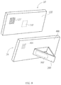
- FIG. 9 is a perspective view of a case assembly 20 according to the second preferred embodiment of the present invention.
- the case assembly 20 can partially cover a wireless communication device 10 ′, and include a case 400 , kickstand structure 200 ′ and an antenna module 300 ′.
- the case 400 is configured to cover the back portion 120 ′ of the wireless communication device 10 ′, such as the protective case for the mobile phone or tablet.
- the technical contents of the kickstand structure 200 ′ and the antenna module 300 ′ can be referred to the kickstand structure 200 and antenna module 300 in the above embodiment.
- the case 400 includes an electrical connector 401 (e.g. a plurality of metal contacts) which is electrically connected to the antenna module 300 ′.
- the wireless communication device 10 ′ also includes an electrical connector 121 ′ disposed on the back portion 120 ′ and electrically connected to the RF signal module 130 ′ in the wireless communication device 10 ′.
- the electrical connector 401 can touch the electrical connector 121 ′ to electrically connect the antenna module 300 ′ with the RF signal module 130 ′ of the wireless communication device 10 ′.
- the wireless communication device 10 ′ can transceive wireless signals through the antenna module 300 ′.
- the wireless communication device and the case assembly of the present invention have a kickstand structure and an antenna module that are capable of arbitrarily adjusting the direction of signal transceiving, thereby eliminating the trouble that the antenna module occupies the internal space of the wireless communication device, and may achieve better signal transmission effect with fewer antenna modules, and have support function to enhance convenience.
Abstract
Description
Claims (5)
Priority Applications (3)
| Application Number | Priority Date | Filing Date | Title |
|---|---|---|---|
| US16/537,984 US10990136B2 (en) | 2019-08-12 | 2019-08-12 | Wireless communication device and case assembly |
| TW108138250A TW202107860A (en) | 2019-08-12 | 2019-10-23 | Wireless communication device and case assembly |
| CN201911049402.XA CN112398979B (en) | 2019-08-12 | 2019-10-31 | Wireless communication device and shell assembly |
Applications Claiming Priority (1)
| Application Number | Priority Date | Filing Date | Title |
|---|---|---|---|
| US16/537,984 US10990136B2 (en) | 2019-08-12 | 2019-08-12 | Wireless communication device and case assembly |
Publications (2)
| Publication Number | Publication Date |
|---|---|
| US20210048843A1 US20210048843A1 (en) | 2021-02-18 |
| US10990136B2 true US10990136B2 (en) | 2021-04-27 |
Family
ID=74567278
Family Applications (1)
| Application Number | Title | Priority Date | Filing Date |
|---|---|---|---|
| US16/537,984 Active US10990136B2 (en) | 2019-08-12 | 2019-08-12 | Wireless communication device and case assembly |
Country Status (3)
| Country | Link |
|---|---|
| US (1) | US10990136B2 (en) |
| CN (1) | CN112398979B (en) |
| TW (1) | TW202107860A (en) |
Families Citing this family (2)
| Publication number | Priority date | Publication date | Assignee | Title |
|---|---|---|---|---|
| CN114089053B (en) * | 2021-08-12 | 2024-03-29 | 山东德源电力科技股份有限公司 | Universal HPLC module tester |
| CN117254242A (en) * | 2022-06-12 | 2023-12-19 | 神基科技股份有限公司 | Millimeter wave communication device |
Citations (3)
| Publication number | Priority date | Publication date | Assignee | Title |
|---|---|---|---|---|
| US6341227B1 (en) * | 1999-06-11 | 2002-01-22 | Telefonaktiebolaget Lm Ericsson (Publ) | Method and apparatus for reducing effect of mismatches and increasing the rigidity of mobile communication device |
| US20130286623A1 (en) * | 2012-04-25 | 2013-10-31 | Motorola Mobility, Inc. | Modular kickstand mechanism |
| US20190393598A1 (en) * | 2018-06-21 | 2019-12-26 | Airspan Networks Inc. | Moveable antenna apparatus |
Family Cites Families (3)
| Publication number | Priority date | Publication date | Assignee | Title |
|---|---|---|---|---|
| TWI376057B (en) * | 2010-02-11 | 2012-11-01 | Htc Corp | Wireless communication device and method thereof |
| CN104868940B (en) * | 2014-02-21 | 2017-07-04 | 晶钛国际电子股份有限公司 | Electronic installation |
| TWI665884B (en) * | 2017-03-13 | 2019-07-11 | 宏達國際電子股份有限公司 | Communication device and communication method |
-
2019
- 2019-08-12 US US16/537,984 patent/US10990136B2/en active Active
- 2019-10-23 TW TW108138250A patent/TW202107860A/en unknown
- 2019-10-31 CN CN201911049402.XA patent/CN112398979B/en active Active
Patent Citations (3)
| Publication number | Priority date | Publication date | Assignee | Title |
|---|---|---|---|---|
| US6341227B1 (en) * | 1999-06-11 | 2002-01-22 | Telefonaktiebolaget Lm Ericsson (Publ) | Method and apparatus for reducing effect of mismatches and increasing the rigidity of mobile communication device |
| US20130286623A1 (en) * | 2012-04-25 | 2013-10-31 | Motorola Mobility, Inc. | Modular kickstand mechanism |
| US20190393598A1 (en) * | 2018-06-21 | 2019-12-26 | Airspan Networks Inc. | Moveable antenna apparatus |
Also Published As
| Publication number | Publication date |
|---|---|
| CN112398979A (en) | 2021-02-23 |
| CN112398979B (en) | 2023-02-28 |
| TW202107860A (en) | 2021-02-16 |
| US20210048843A1 (en) | 2021-02-18 |
Similar Documents
| Publication | Publication Date | Title |
|---|---|---|
| KR102233837B1 (en) | Electronic devices having communications and ranging capabilities | |
| US11239572B2 (en) | Beam-steering reconfigurable antenna arrays | |
| CN112751170B (en) | Electronic device with 5G antenna | |
| EP2195879B1 (en) | Antenna array with flexible interconnect for a mobile wireless device | |
| US6509877B2 (en) | Portable information apparatus incorporating radio communication antenna | |
| US8638263B2 (en) | Platform enhancements for planar array antennas | |
| US8154467B2 (en) | Antenna apparatus and wireless communication terminal | |
| US11380986B2 (en) | Wireless communication device and method | |
| US20120062423A1 (en) | Portable device with smart antenna | |
| JP2005520383A (en) | Adaptive receive and omnidirectional antenna arrays | |
| US8223077B2 (en) | Multisector parallel plate antenna for electronic devices | |
| US20200091581A1 (en) | Flex integrated antenna array | |
| WO2006062059A1 (en) | Portable wireless unit | |
| US10990136B2 (en) | Wireless communication device and case assembly | |
| US20230369778A1 (en) | Antenna module and electronic device including same | |
| EP4164061A1 (en) | Dual polarization antenna and electronic device including same | |
| US20040140937A1 (en) | Mobile computer with an integrated directional antenna | |
| CN116057848A (en) | Method and electronic device for controlling transmission power of multi-beam transmission | |
| JPWO2009130775A1 (en) | Planar antenna device and communication device | |
| JP2003309499A (en) | Portable information equipment | |
| US20240072414A1 (en) | Antenna module for vehicle and vehicle including the same | |
| CN218940000U (en) | Antenna assembly and electronic equipment | |
| CN218602748U (en) | Millimeter wave antenna module and communication equipment | |
| CN112965634A (en) | Display module and electronic equipment | |
| CN117178432A (en) | Antenna structure including phase shifter and electronic device including the same |
Legal Events
| Date | Code | Title | Description |
|---|---|---|---|
| AS | Assignment |
Owner name: HT, TAIWAN Free format text: ASSIGNMENT OF ASSIGNORS INTEREST;ASSIGNORS:LIN, CHENG HUNG;WANG, SZU PO;LEE, CHUN HSIEN;REEL/FRAME:050025/0317 Effective date: 20190806 |
|
| FEPP | Fee payment procedure |
Free format text: ENTITY STATUS SET TO UNDISCOUNTED (ORIGINAL EVENT CODE: BIG.); ENTITY STATUS OF PATENT OWNER: LARGE ENTITY |
|
| AS | Assignment |
Owner name: HTC CORPORATION, TAIWAN Free format text: ASSIGNMENT OF ASSIGNORS INTEREST;ASSIGNORS:LIN, CHENG HUNG;WANG, SZU PO;LEE, CHUN HSIEN;REEL/FRAME:050058/0819 Effective date: 20190806 |
|
| STPP | Information on status: patent application and granting procedure in general |
Free format text: DOCKETED NEW CASE - READY FOR EXAMINATION |
|
| STPP | Information on status: patent application and granting procedure in general |
Free format text: NOTICE OF ALLOWANCE MAILED -- APPLICATION RECEIVED IN OFFICE OF PUBLICATIONS |
|
| STPP | Information on status: patent application and granting procedure in general |
Free format text: PUBLICATIONS -- ISSUE FEE PAYMENT RECEIVED |
|
| STPP | Information on status: patent application and granting procedure in general |
Free format text: PUBLICATIONS -- ISSUE FEE PAYMENT VERIFIED |
|
| STCF | Information on status: patent grant |
Free format text: PATENTED CASE |