US10978932B2 - Drone for triggering sea mines - Google Patents
Drone for triggering sea mines Download PDFInfo
- Publication number
- US10978932B2 US10978932B2 US16/081,282 US201716081282A US10978932B2 US 10978932 B2 US10978932 B2 US 10978932B2 US 201716081282 A US201716081282 A US 201716081282A US 10978932 B2 US10978932 B2 US 10978932B2
- Authority
- US
- United States
- Prior art keywords
- drone
- rotor
- electric motor
- carrier
- stator
- Prior art date
- Legal status (The legal status is an assumption and is not a legal conclusion. Google has not performed a legal analysis and makes no representation as to the accuracy of the status listed.)
- Expired - Fee Related, expires
Links
Images


Classifications
-
- H—ELECTRICITY
- H02—GENERATION; CONVERSION OR DISTRIBUTION OF ELECTRIC POWER
- H02K—DYNAMO-ELECTRIC MACHINES
- H02K7/00—Arrangements for handling mechanical energy structurally associated with dynamo-electric machines, e.g. structural association with mechanical driving motors or auxiliary dynamo-electric machines
- H02K7/14—Structural association with mechanical loads, e.g. with hand-held machine tools or fans
-
- B—PERFORMING OPERATIONS; TRANSPORTING
- B63—SHIPS OR OTHER WATERBORNE VESSELS; RELATED EQUIPMENT
- B63G—OFFENSIVE OR DEFENSIVE ARRANGEMENTS ON VESSELS; MINE-LAYING; MINE-SWEEPING; SUBMARINES; AIRCRAFT CARRIERS
- B63G7/00—Mine-sweeping; Vessels characterised thereby
- B63G7/02—Mine-sweeping means, Means for destroying mines
- B63G7/06—Mine-sweeping means, Means for destroying mines of electromagnetic type
-
- H—ELECTRICITY
- H02—GENERATION; CONVERSION OR DISTRIBUTION OF ELECTRIC POWER
- H02K—DYNAMO-ELECTRIC MACHINES
- H02K11/00—Structural association of dynamo-electric machines with electric components or with devices for shielding, monitoring or protection
- H02K11/01—Structural association of dynamo-electric machines with electric components or with devices for shielding, monitoring or protection for shielding from electromagnetic fields, i.e. structural association with shields
- H02K11/014—Shields associated with stationary parts, e.g. stator cores
-
- H—ELECTRICITY
- H02—GENERATION; CONVERSION OR DISTRIBUTION OF ELECTRIC POWER
- H02K—DYNAMO-ELECTRIC MACHINES
- H02K55/00—Dynamo-electric machines having windings operating at cryogenic temperatures
-
- H—ELECTRICITY
- H02—GENERATION; CONVERSION OR DISTRIBUTION OF ELECTRIC POWER
- H02K—DYNAMO-ELECTRIC MACHINES
- H02K55/00—Dynamo-electric machines having windings operating at cryogenic temperatures
- H02K55/02—Dynamo-electric machines having windings operating at cryogenic temperatures of the synchronous type
-
- H—ELECTRICITY
- H02—GENERATION; CONVERSION OR DISTRIBUTION OF ELECTRIC POWER
- H02K—DYNAMO-ELECTRIC MACHINES
- H02K99/00—Subject matter not provided for in other groups of this subclass
- H02K99/20—Motors
-
- B—PERFORMING OPERATIONS; TRANSPORTING
- B63—SHIPS OR OTHER WATERBORNE VESSELS; RELATED EQUIPMENT
- B63G—OFFENSIVE OR DEFENSIVE ARRANGEMENTS ON VESSELS; MINE-LAYING; MINE-SWEEPING; SUBMARINES; AIRCRAFT CARRIERS
- B63G7/00—Mine-sweeping; Vessels characterised thereby
- B63G2007/005—Unmanned autonomously operating mine sweeping vessels
-
- H—ELECTRICITY
- H02—GENERATION; CONVERSION OR DISTRIBUTION OF ELECTRIC POWER
- H02K—DYNAMO-ELECTRIC MACHINES
- H02K11/00—Structural association of dynamo-electric machines with electric components or with devices for shielding, monitoring or protection
-
- Y—GENERAL TAGGING OF NEW TECHNOLOGICAL DEVELOPMENTS; GENERAL TAGGING OF CROSS-SECTIONAL TECHNOLOGIES SPANNING OVER SEVERAL SECTIONS OF THE IPC; TECHNICAL SUBJECTS COVERED BY FORMER USPC CROSS-REFERENCE ART COLLECTIONS [XRACs] AND DIGESTS
- Y02—TECHNOLOGIES OR APPLICATIONS FOR MITIGATION OR ADAPTATION AGAINST CLIMATE CHANGE
- Y02E—REDUCTION OF GREENHOUSE GAS [GHG] EMISSIONS, RELATED TO ENERGY GENERATION, TRANSMISSION OR DISTRIBUTION
- Y02E40/00—Technologies for an efficient electrical power generation, transmission or distribution
- Y02E40/60—Superconducting electric elements or equipment; Power systems integrating superconducting elements or equipment
Definitions
- the present disclosure relates to drones.
- Various embodiments may include a drone for triggering sea mines by means of an external magnetic field.
- unmanned drones are equipped with magnetic coils for the purpose of triggering magnetic mines. Said coils generate strong magnetic fields that are capable of causing the sea mines to detonate.
- the drones are constructed in such a way that at the distance that is typical for the triggering they suffer no damage as a result of the detonation.
- Such drones may have their own dedicated drive system.
- the German Navy for example, possesses remotely controllable boats of the “Seehund” (seal) type, which are fitted with a diesel engine.
- the magnetic coil for triggering the mines is integrated into the hull of the remotely controllable boats.
- the magnetic coil itself is formed from a plurality of turns made of copper cable.
- the magnetic coil is also embodied as a separate unit from the drive device.
- the prior art mine-clearing drones are very heavy due to the great weight of the magnetic coils required for the strong magnetic fields, and in most cases they are also relatively large. For this reason, the transportation of such drones to different deployment locations is a relatively complicated operation. Transportation by plane in particular is rather difficult on account of the heavy weight.
- the propulsion engine also makes its contribution to the heavy weight and volume.
- an additional energy supply is also necessary for the drive, for example in the form of fuel for a diesel engine or alternatively in the form of electrically stored energy for an electric motor.
- the teachings of the present disclosure may be embodied in a drone for triggering sea mines by means of an external magnetic field which overcomes the cited disadvantages.
- a drone which may be comparatively small and with a lightweight form and which nonetheless possesses its own dedicated drive as well as a magnetic triggering system.
- some embodiments may include a drone ( 1 ) for triggering sea mines by means of an external magnetic field (B ext ), wherein the drone ( 1 ) comprises a drive having an electric motor ( 3 ) for locomotion in water, wherein the electric motor ( 3 ) comprises a stator ( 11 ) and a rotor ( 9 ) that is rotatably mounted on a rotor shaft ( 7 ), wherein the stator ( 11 ) has at least one stator winding ( 17 ) which is arranged on a first carrier ( 19 ), wherein the rotor ( 9 ) has a second carrier ( 20 ) and, arranged thereon, at least one magnetic or electromagnetic element ( 15 a , 15 b , 15 c ) which is able to interact electromagnetically with the at least one stator winding ( 17 ) in such a way that a superordinate magnetic field (B) is formed during operation of the electric motor ( 3 ), and wherein the electric motor ( 3 ) is embodied in such
- the electric motor ( 3 ) is embodied in such a way that the rotor ( 9 ) is arranged radially inside the stator ( 11 ).
- the electric motor ( 3 ) is embodied in such a way that the stator ( 11 ) is arranged radially inside the rotor ( 9 ).
- the magnetic properties of the first carrier ( 19 ) and/or of the second carrier ( 20 ) are embodied in such a way that, during the operation of the electric motor ( 3 ), a magnetic flux of at least 0.5 mT is able to penetrate into an area outside of the electric motor ( 3 ).
- the first carrier ( 19 ) and/or the second carrier ( 20 ) are/is embodied at least in sections from a material which has an effective relative permeability number ⁇ r of at most 300, in particular at most 10.
- the electric motor ( 3 ) has a nonmagnetic motor housing ( 13 ).
- the electric motor ( 3 ) is embodied as a synchronous motor, wherein the rotor ( 9 ) has at least one element ( 15 a , 15 b ) for generating a magnetic field, in particular at least one permanent magnet ( 15 a ) and/or at least one electrical field coil ( 15 b ).
- the electric motor ( 3 ) is embodied as an asynchronous motor, wherein the rotor ( 9 ) has, as the electromagnetic element, at least one element for forming a closed current path, in particular a squirrel cage or at least one annularly short-circuited or short-circuitable rotor coil.
- the first carrier ( 19 ) and/or the second carrier ( 20 ) is embodied at least in sections from a material which comprises a nonmagnetic steel and/or plastic.
- the electric motor ( 3 ) comprises at least one superconducting element ( 21 ).
- the rotor ( 9 ) comprises at least one block ( 21 a ) made of superconducting material in which a magnetic flux may be impressed in such a way that the at least one block ( 21 a ) acts like a permanent magnet.
- the rotor ( 9 ) comprises at least one block ( 21 b ), wherein each block in each case comprises a plurality of stacked superconducting tape conductors ( 21 c ), and wherein a magnetic flux may be impressed in the respective block ( 21 b ) in such a way that the block ( 21 b ) acts like a permanent magnet.
- the rotor ( 9 ) has at least one superconducting field coil ( 23 ).
- the at least one stator winding ( 17 ) has a superconducting electrical conductor ( 21 ).
- the superconducting electrical conductor ( 21 ) comprises a high-temperature superconducting material, in particular magnesium diboride and/or a material of the type REBa 2 Cu 3 O x .
- FIG. 1 shows a drone 1 in a schematic longitudinal section, according to the teachings herein;
- FIGS. 2 to 5 show exemplary motors 3 in a schematic cross-section, according to the teachings herein.
- Various embodiments of the teachings herein may include a drone suitable for triggering sea mines by means of a magnetic field.
- Some embodiments may comprise a drive having an electric motor for providing locomotion in water, the electric motor comprising a stator and a rotor that is rotatably mounted on a rotor shaft.
- the stator has at least one stator winding which is arranged on a first carrier.
- the rotor has a second carrier and, arranged thereon, at least one magnetic or electromagnetic element which is able to interact electromagnetically with the at least one stator winding in such a way that a superordinate magnetic field is formed during operation of the electric motor.
- the electric motor is configured in such a way that, during its operation, the external magnetic field that is formed outside of the electric motor achieves a magnetic flux density of at least 0.5 mT at said location in at least a subarea of said external environment.
- a drone is able, owing to the interaction of rotor and stator, to form an electromagnetic field that is necessary for its operation.
- the electric motor is furthermore configured in such a way that, during its operation, a magnetic flux of at least the cited threshold value is able to penetrate into an area outside of the electric motor.
- the electric motor as a whole, and in particular the carrier of the stator windings are embodied in such a way that a penetration of such a high proportion of the magnetic flux into said external areas outside of the electric motor is not prevented.
- the at least one stator winding “on a first carrier” is to be generally understood in the present context that said winding is held in some way or other by said first carrier.
- the winding(s) is (are) mounted on a surface of the carrier or whether the first carrier spatially encloses the windings at least partially.
- the winding(s) may be mounted radially internally or externally on the carrier or may also be embedded into the same.
- the external magnetic field is a magnetic field at a location outside of the electric motor.
- the magnetic field used for the drive during the operation of the electric motor may be used in addition for triggering the sea mines.
- magnetic flux is typically prevented from penetrating into external areas, among other reasons in order to comply with accepted standards relating to electromagnetic compatibility.
- magnetic flux-conducting materials are employed which annularly close the magnetic flux around the internal components of the motor and stop the flux form penetrating into areas lying outside of the rotor.
- the rotor is arranged radially inside the stator.
- it may be of a type known as an internal rotor machine.
- the magnetic properties of the carrier of the at least one stator winding may then be embodied in such a way that, when the electric motor is in operation, a magnetic flux of at least 0.5 mT is able to penetrate into an area outside of the electric motor.
- the carrier of the stator winding(s) may typically completely enclose the rotor radially. It may, for example, be a cylindrical carrier with a circular internal profile, on the inside of which the stator winding(s) is (are) embedded.
- the magnetic properties of said carrier are embodied in such a way that a sufficiently strong penetration of the magnetic field outward is not prevented.
- the magnetic properties of the rest of the components for example an exterior wall of the drone, it is possible in this way to generate even a magnetic field exceeding the cited threshold value outside of the drone as a whole.
- the carrier of the stator windings typically includes a stator iron yoke which annularly closes the magnetic flux around the internal rotor and effectively prevents the magnetic flux from penetrating into external areas.
- a stator iron yoke which annularly closes the magnetic flux around the internal rotor and effectively prevents the magnetic flux from penetrating into external areas.
- the first carrier enclosing the rotor does not close the magnetic flux annularly above and beyond the structure of the first carrier.
- the first carrier enclosing the rotor in the manner of a circular cylinder and is therefore not flux-conducting in a closed manner in the azimuthal direction.
- it may be completely nonmagnetic, for example.
- it may comprise soft-magnetic segments which only conduct magnetic flux into radially external areas, but not to form a closed magnetic flux in the circumferential direction of the rotor.
- Soft-magnetic azimuthal carrier segments may therefore alternate with nonmagnetic carrier segments in order to enable a desired flux conduction of the superordinate magnetic field and in particular also to conduct the magnetic field outward in the radial direction without closing the flux in the circumferential direction.
- the carrier of the stator winding(s) may comprise multiple sections of a material which has an effective permeability number ⁇ r —also known as relative permeability—of at most 300.
- the effective permeability number ⁇ r is around at most 10 only or even around at most 5 only.
- the first carrier may comprise multiple sections of a material which comprises a nonmagnetic steel and/or plastic.
- a plastic-containing material may for example comprise a resin, a thermoplastic, a duroplastic, and/or a glass fiber reinforced plastic.
- the electric motor may comprise a stator arranged inside the rotor. It may therefore be of a type known as an external rotor machine. A high external magnetic field may be generated in a particularly simple manner by means of such an electric motor if the rotor has at least one element for generating a magnetic field and no annularly closed soft-magnetic element is arranged radially outside of the rotor.
- the carrier of the rotor i.e. the second carrier
- the second carrier allows a magnetic flux of at least 0.5 mT to penetrate into an area outside of the electric motor during the operation of the electric motor.
- the then external second carrier may be analogous to the described embodiment variants of the external first carrier.
- the second carrier may comprise multiple sections of a corresponding weakly magnetic material. The remaining various embodiments for the carrier are in each case also applicable in particular to that carrier of the two carriers that is disposed radially further outward in the respective machine geometry (internal rotor or external rotor).
- the magnetic properties of the carrier disposed radially further outward may be embodied in such a way that a magnetic flux of at least 0.5 mT is able to penetrate into an area outside of the electric motor during the operation of the electric motor.
- the electric motor may have a nonmagnetic housing. In this way it is possible to ensure that the magnetic flux also penetrates such a motor housing, and that a sufficiently high external magnetic field for triggering a magnetic mine can be generated.
- the magnetic coupling between stator and rotor is reduced significantly in comparison with conventional motors. Without additional modification, this may lead to a lower power output of the electric motor. In order to compensate for this, additional measures may be taken, as is described in greater detail further below for some instances.
- superconducting elements may be employed in the stator and/or rotor in order to generate stronger magnetic fields within a comparable or even smaller design footprint. Even in the case of normally conducting components, measures may be adopted in order to compensate for the lower coupling.
- the motor may be implemented longer in the axial direction than would be the case for a comparable motor with stator iron yoke.
- the electric motor may comprise a synchronous motor.
- the rotor may comprise at least one element for generating a magnetic field.
- said element may be at least one permanent magnet and/or at least one electrical field coil.
- Such a permanently excited electric motor is particularly well suited for generating a comparatively high superordinate magnetic field.
- the electric motor may comprise an asynchronous motor.
- the rotor may comprise, as the electromagnetic element, at least one element for forming a closed current path.
- This may be in particular a squirrel cage and/or at least one annularly short-circuited or short-circuitable rotor coil.
- a short-circuitable though not permanently short-circuited rotor coil may be present, for example, in a type of rotor known as a slip ring rotor. Even with such an asynchronous motor, it is possible to generate sufficiently high external magnetic fields for triggering magnetic mines by means of the electromagnetic interaction of rotor and stator.
- a magnetic flux density of at least 5 mT in particular at least 50 mT, or even at least 500 mT, at least in a subarea thereof.
- an exterior wall of the drone may also be formed from nonmagnetic material. What is to be generally understood by a nonmagnetic material in connection with the present invention is a material having a relative permeability ⁇ r of at most 300.
- the electric motor may comprise at least one superconducting element.
- superconducting materials it is possible to generate comparatively high magnetic fields using relatively small and lightweight components, which contributes in a particularly advantageous manner to the objective of providing a small and lightweight drone.
- the electrical components of the rotor and stator may also comprise normally conducting components exclusively, and the basic idea of the present invention may be realized nonetheless.
- the rotor of the electric motor may comprise at least one block composed of superconducting material in which a magnetic flux may be impressed in such a way that the at least one block acts like a permanent magnet.
- a block may be a block formed from bulk superconducting material.
- there may also be a plurality of such blocks present in order to generate a particularly high, constant magnetic field.
- a magnetic flux may be impressed at a temperature above the critical or transition temperature at the location of the superconductor by means of an external magnetic coil or else a permanent magnet, said magnetic flux then being frozen in the superconducting material by cooling to a temperature below the critical temperature of the superconductor.
- Such methods are known in the prior art by the terms “field cooling” and “zero field cooling”.
- An alternative method is the flux pump method. In this case, a magnetization is impressed in the superconducting material by way of magnetic field pulses at a cryogenic temperature below the critical temperature.
- a common feature shared by all of these methods is that the magnetic flux is retained in the superconductor after the external magnet used to impress the magnetization is removed, and the superconductor acts as a permanent magnet for as long as it is maintained at a temperature below its critical temperature.
- Such blocks may also be composed in each case of a plurality of superconducting tape conductors.
- such a block may be formed as a stack of such tape conductors.
- a magnetic flux may then be impressed in the respective block in such a way that the block acts like a permanent magnet, as described above.
- no energy is required to maintain the rotor magnetic field. Accordingly, there is also no need for any current supply leads from the warmer external environment to the cryogenic environment of the superconductor material, and the thermal losses occurring when the superconductor is cooled to a temperature below its critical temperature may be kept low. Because such superconducting components are not only easy to magnetize, but also easy to demagnetize—by heating, for example—they are also easily transportable. For example, electromagnetic compatibility requirements may be easily complied with when the superconducting components of the drone are not magnetized at times during which the drone is not in service.
- the rotor may comprise at least one superconducting field coil.
- a field excitation winding of the rotor may be supplied with electrical energy by way of a direct-current source, for example.
- a direct-current source for example.
- the field excitation winding of such a drone may then be charged by means of an external current source prior to deployment of the drone, and the field excitation winding of the drone may be operated during the latter's deployment of, for example, several hours without a current source for the field excitation winding(s).
- electrical connections of the field excitation winding may also be dispensed with, as a result of which the thermal losses in the cryogenic environment of the superconducting winding(s) can be reduced.
- the electric motor may be constructed in a smaller and more lightweight format than would be possible with normally conducting windings, for example conventional copper windings.
- normally conducting windings for example conventional copper windings.
- the electric motor may also be embodied in such a way that its stator winding comprises a superconducting electrical conductor.
- its stator winding comprises a superconducting electrical conductor.
- significantly higher stator currents and/or significantly higher numbers of turns may be realized within the same construction volume compared to conventional copper windings.
- the construction volume, and consequently also the weight, of the drone can also be reduced compared to a motor comprising normally conducting materials.
- Superconducting stator windings of said type enable a high external magnetic field to be realized outside of the electric motor.
- HTS high-temperature superconductors
- the cuprate superconductors in excess of 77 K, in which the operating temperature can be reached by cooling with cryogenic materials other than liquid helium.
- Another reason why HTS materials are particularly attractive is that, depending on the choice of operating temperature, said materials can have high upper critical magnetic fields as well as high critical current densities. With such materials it is therefore particularly easy to generate high magnetic fields.
- such a high-temperature superconducting material may comprise magnesium diboride and/or a material of the type REBa 2 Cu 3 O x , where RE stands for a rare earth element or a mixture of such elements.
- RE stands for a rare earth element or a mixture of such elements.
- the superconducting conductor may advantageously be implemented as a tape conductor.
- drone may comprise an energy store for storing electrical or chemical energy for the operation of the electric motor.
- the drone may have an electric battery and/or it may have a fuel tank for an electric generator.
- the drone may in principle also be supplied with energy during its deployment by a control system, for example a larger ship, through a cable connection.
- the drone may be embodied in such a way that the electric motor forms the sole magnetic triggering system for triggering sea mines. In that case there are therefore no further magnetic coils or permanent magnets present for generating an external magnetic field above the triggering threshold of sea mines. In some embodiments, however, there may well be an additional acoustic triggering system also present for triggering acoustic mines. In principle it is also conceivable that a further magnetic triggering system also be present, for example when a magnetic flux curve deviating from the magnetic field of the electric motor is to be generated or when a time-variable magnetic flux is to be generated.
- the electric motor may have a pole pair number between 1 and 5. With such a comparatively low pole pair number, it is relatively easy to generate a magnetic flux having a relatively high radial range in an outward direction. A relatively high external magnetic field for triggering the mines may therefore be easily made available.
- the drone may advantageously be embodied to be moved under water. In some embodiments, however, it may in principle also be embodied as a drone floating on a water surface.
- FIG. 1 shows a drone 1 according to a first exemplary embodiment in a schematic longitudinal section.
- the figure depicts a drone of elongate shape which is designed for locomotion under water. At its rearward portion (shown on the left in the drawing), it has a propeller.
- the drone is therefore equipped with an independent propulsion system, the propeller being driven in this case by way of a rotor shaft 7 of an electric motor 3 .
- the electric motor 3 occupies a large portion of the available interior space of the drone.
- the space taken up by the electric motor 3 may in principle also turn out to be smaller, for example in order to make space available for a control unit for controlling the motor and other steering units (not shown here) for guiding the drone.
- an energy store in the form of a battery may also be present in the interior of the drone.
- a fuel tank for example a diesel tank, and a generator for supplying the motor with electrical energy may be provided.
- a further alternative may be to supply the electric motor 3 with energy via an electric cable (not shown here).
- the electric motor 3 comprises a rotor 9 which is arranged on the rotor shaft 7 and is coupled to the latter in a torque-locking manner in such a way that the propeller 5 can be driven via the rotor shaft 7 .
- the electric motor 3 additionally comprises a stator 11 which is arranged radially outside of the rotor 9 . In this arrangement the motor is therefore an internal rotor motor.
- the stator is in this case provided with a plurality of stator windings, the winding overhangs of which are represented schematically as small loops in the axial end regions of the stator 11 .
- FIG. 2 shows a schematic cross-section of such an exemplary electric motor 3 .
- the stator 11 comprises a plurality of stator windings 17 which are retained by a first carrier 19 of the stator 11 .
- Said stator windings are embedded on the radially internal side of said circular cylindrical first carrier 19 between teeth 19 a that are present there.
- the rotor 9 has a four-pole arrangement of permanent magnets 15 a which are disposed symmetrically around the rotor shaft 7 .
- the permanent magnets 15 a are embodied in such a way that two north poles N and two south poles S are located in alternating fashion on the radially external surface.
- the rotor 9 rotates inside the stator 11 , and a time-variable superordinate magnetic field B as well as the torque for the drive are generated as a result of the electromagnetic interaction between the permanent magnets 15 a and the stator windings 17 .
- the first carrier 19 is embodied in its entirety from a nonmagnetic material, for example a nonmagnetic steel. This enables the formed magnetic flux to penetrate a good distance radially outward, above and beyond the structure of the stator 11 and the first carrier 19 , as indicated by the field line drawn by way of example for the magnetic field B.
- the electric motor 3 is configured overall in such a way that an external magnetic field having a magnetic flux in excess of at least one of the previously cited threshold values may also be established outside of the motor housing 13 (not shown in FIG. 2 ). This means that magnetic fields B that are sufficient for triggering magnetic mines may also be generated outside of the drone as a whole.
- the stator windings 17 may be embodied as conventional normally conducting windings, made of copper, for example. Alternatively, however, they may also be formed from superconducting conductors 21 , as indicated in FIG. 2 for one of the stator windings by way of example.
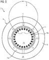
- FIG. 3 A further exemplary embodiment variant of the electric motor 3 is shown in FIG. 3 .
- Said electric motor 3 is likewise shown in a schematic cross-section here, in this case together with its motor housing 13 .
- the motor housing has a rectangular cross-section in this example. In some embodiments, however, it may also have a round, in particular circular cross-section, or the cross-section may at least have rounded corners or be formed as a polygon having more than four corners so that the electric motor 3 takes up less space in the interior of the drone.
- Corresponding housings may also find application for the electric motors of the other exemplary embodiments and are not shown there simply for clarity of illustration reasons.
- the components of the electric motor 3 are configured overall in such a way that the external magnetic field B ext outside of the motor housing has a magnetic flux equal to at least one of the previously cited threshold values.
- the rotor 9 comprises no permanent magnets, but is equipped with four field coils 15 b , which serve to generate the excitation magnetic field.
- the rotor 9 is embodied, exactly as in the first exemplary embodiment, as a four-pole rotor, i.e. there are two pole pairs.
- the configuration and effect of the stator windings 17 are in this case analogous to the described first exemplary embodiment.
- the stator windings may be formed in this case also either from normally conducting conductors or else also from superconducting conductors 21 , as indicated for one of the stator windings by way of example.
- FIG. 4 shows a further exemplary embodiment of an electric motor 3 according to the teachings of the present disclosure.
- the rotor 9 comprises a plurality of superconducting blocks 21 a or 21 b in which a magnetic flux can be impressed in such a way that the block 21 a or 21 b acts like a permanent magnet.
- Said blocks may be embodied in different forms.
- the blocks 21 a may be embodied as superconducting solid bodies, as shown in FIG. 4 for three of the blocks by way of example. In such an embodiment variant, however, all of the blocks present would advantageously be embodied as superconducting solid bodies of said type.
- FIG. 4 shows a further exemplary embodiment of an electric motor 3 according to the teachings of the present disclosure.
- the rotor 9 comprises a plurality of superconducting blocks 21 a or 21 b in which a magnetic flux can be impressed in such a way that the block 21 a or 21 b acts like a permanent magnet.
- Said blocks may be embodie
- FIG. 4 is shown only by way of example as a composite superconducting block 21 b , which is formed by a plurality of stacks of, in each case, a plurality of superconducting tape conductors 21 c superimposed on one another.
- all superconducting blocks of the rotor would then correspondingly also advantageously be constructed similarly to one another.
- these are in any case suitable for allowing a predefined magnetic flux to be impressed, for example frozen, in them so that a magnetic field can be generated by the rotor 9 without requiring a separate dedicated current source for this purpose during operation.
- the first carrier 19 of the stator windings 17 is not required to be embodied throughout from a uniform material.
- FIG. 4 shows in the lower left section of the first carrier 19 that this may be composed of alternating azimuthal segments made of different materials. In the section shown, these are radially continuous, soft-magnetic carrier segments 25 between the slots into which the stator windings 17 are embedded and nonmagnetic carrier segments 27 arranged radially outside of said slots. Other configurations are also possible, however.
- the important point is that the first carrier 19 is generally not formed throughout from soft-magnetic material in an annularly continuous manner.
- the described segmentation of the first carrier 19 is generally also applicable to the other embodiments of the electric motor shown in FIG. 2 or 3 .
- FIG. 5 shows by way of example an external rotor motor in which the rotatably mounted rotor 9 therefore radially surrounds the stationary stator 11 .
- the second carrier 20 which is part of the rotor 9 , radially surrounds the first carrier 19 , which is part of the stator 11 .
- the stator windings 17 are arranged in slots between teeth 19 a of the carrier 19 of the stator 11 , albeit, in contrast to the internal rotor motors, on the radially external side of said carrier 19 .
- the carrier 20 of the rotor supports the magnetic or electromagnetic elements which, together with the stator winding, generate the superordinate magnetic field, for which, once again by way of example, a field line B is drawn in the figure.
- said elements are permanent magnets 15 a .
- normally conducting and/or superconducting field coils 15 b as well as solid or composite superconducting blocks 21 a or 21 b , may also find application in the external rotor motor, analogously to the examples of FIGS. 3 and 4 for the internal rotor motor.
- the stator windings 17 may be embodied analogously to the different variants of the internal rotor motor in this case also as normally conducting or else as superconducting windings.
- the second carrier 20 of the rotor 9 which in this case is the further outward of the two carriers, may be embodied in such a way that a high proportion of the magnetic flux is conducted in an outward direction such that an external magnetic field having a correspondingly high magnetic flux B ext is also generated outside of a motor housing (not shown here), analogously to the described advantageous embodiment variants of the internal rotor motor.
- the second carrier 20 is therefore not embodied as a soft-magnetic yoke which conducts the magnetic flux inside the carrier.
Landscapes
- Engineering & Computer Science (AREA)
- Power Engineering (AREA)
- Physics & Mathematics (AREA)
- Electromagnetism (AREA)
- Aviation & Aerospace Engineering (AREA)
- Superconductive Dynamoelectric Machines (AREA)
Abstract
Description
Claims (17)
Applications Claiming Priority (3)
| Application Number | Priority Date | Filing Date | Title |
|---|---|---|---|
| DE102016203341.7 | 2016-03-01 | ||
| DE102016203341.7A DE102016203341A1 (en) | 2016-03-01 | 2016-03-01 | Drone for triggering sea mines |
| PCT/EP2017/052154 WO2017148642A1 (en) | 2016-03-01 | 2017-02-01 | Drone for triggering sea mines |
Publications (2)
| Publication Number | Publication Date |
|---|---|
| US20190092440A1 US20190092440A1 (en) | 2019-03-28 |
| US10978932B2 true US10978932B2 (en) | 2021-04-13 |
Family
ID=57984922
Family Applications (1)
| Application Number | Title | Priority Date | Filing Date |
|---|---|---|---|
| US16/081,282 Expired - Fee Related US10978932B2 (en) | 2016-03-01 | 2017-02-01 | Drone for triggering sea mines |
Country Status (6)
| Country | Link |
|---|---|
| US (1) | US10978932B2 (en) |
| EP (1) | EP3405387B1 (en) |
| AU (1) | AU2017225324B2 (en) |
| DE (1) | DE102016203341A1 (en) |
| ES (1) | ES2800156T3 (en) |
| WO (1) | WO2017148642A1 (en) |
Families Citing this family (8)
| Publication number | Priority date | Publication date | Assignee | Title |
|---|---|---|---|---|
| DE102016203341A1 (en) | 2016-03-01 | 2017-09-07 | Siemens Aktiengesellschaft | Drone for triggering sea mines |
| DE102018217211A1 (en) * | 2018-10-09 | 2020-04-09 | Siemens Aktiengesellschaft | Drone for triggering sea mines with an electric drive |
| DE102018218473A1 (en) * | 2018-10-29 | 2020-04-30 | Rolls-Royce Deutschland Ltd & Co Kg | Rotor, machine and method for magnetizing |
| FR3093599A1 (en) * | 2019-03-07 | 2020-09-11 | Safran | Superconducting electrical machine and method of magnetizing superconducting pellets |
| DE102019212105A1 (en) * | 2019-08-13 | 2021-02-18 | Siemens Aktiengesellschaft | Operating procedures for a mine clearance system and a mine clearance system for triggering sea mines |
| DE102019216155A1 (en) | 2019-10-21 | 2021-04-22 | Siemens Aktiengesellschaft | Watercraft and method for operating a watercraft |
| DE102020208027A1 (en) | 2020-06-29 | 2021-12-30 | Siemens Aktiengesellschaft | Drone for triggering sea mines with an electric propulsion device |
| KR20230161602A (en) * | 2022-05-19 | 2023-11-28 | 현대자동차주식회사 | Motor and controlling method of the same |
Citations (25)
| Publication number | Priority date | Publication date | Assignee | Title |
|---|---|---|---|---|
| US3775626A (en) | 1971-01-29 | 1973-11-27 | Papst Motoren Kg | External-rotor reluctance motor |
| BE832177A (en) | 1975-08-06 | 1975-12-01 | ORDER FOR BOATS. | |
| US3946696A (en) * | 1969-12-05 | 1976-03-30 | The United States Of America As Represented By The Secretary Of The Navy | Automatically controlled magnetic minesweeping system |
| US4220108A (en) * | 1968-09-27 | 1980-09-02 | Burt Wayne E | Minesweeping method and apparatus |
| JPS5876395A (en) | 1981-10-30 | 1983-05-09 | Sumitomo Electric Ind Ltd | minesweeping equipment |
| EP0125180A1 (en) | 1983-05-03 | 1984-11-14 | Thomson-Csf | Remote mine-sweeping apparatus for mines with magnetic firing means |
| EP0289692A1 (en) | 1987-05-04 | 1988-11-09 | ACEC, Société Anonyme | Mine-sweeping device |
| NL8702274A (en) | 1987-09-24 | 1989-04-17 | Louris Bood | Electric motor for use in mine sweepers - has radical gap in stator and housing for supply wires, wound grooves and mu-metal casing |
| NL8802840A (en) | 1987-11-18 | 1989-06-16 | Combimac Beheer B V | Rotary electric machine commutatorless three=phase - has auxiliary winding to minimise external effect of stray stator fields |
| US4885494A (en) * | 1987-11-27 | 1989-12-05 | Mitsubishi Denki Kabushiki Kaisha | Motor and motor device |
| US5273465A (en) | 1993-02-11 | 1993-12-28 | The United States Of America As Represented By The Secretary Of The Navy | Magnetohydrodynamic boundary layer control system |
| DE9420497U1 (en) | 1994-12-22 | 1995-04-27 | Fr. Lürssen Werft GmbH & Co, 28759 Bremen | Mine clearance vehicle |
| US5598152A (en) * | 1994-12-29 | 1997-01-28 | The United States Of America As Represented By The Secretary Of The Navy | Mine sweeping system for magnetic and non-magnetic mines |
| US5808392A (en) | 1994-04-28 | 1998-09-15 | Kabushiki Kaisha Toshiba | Permanent magnet type rotating machine |
| US6213021B1 (en) | 1999-12-16 | 2001-04-10 | The United States Of America As Represented By The Secretary Of The Navy | Electromagnetic sea mine detonation system |
| WO2002041474A1 (en) | 2000-11-15 | 2002-05-23 | Qinetiq Limited | Low magnetic signature motor system |
| US6634273B2 (en) * | 2001-05-15 | 2003-10-21 | Edo Corporation | Open loop minesweeping system |
| US20040042150A1 (en) | 2000-01-27 | 2004-03-04 | Swinbanks Malcolm A. | Dynamic degaussing system |
| WO2004054873A1 (en) | 2002-12-18 | 2004-07-01 | Commonwealth Of Australia | Minesweeping device |
| EP1901418A1 (en) | 2006-09-13 | 2008-03-19 | Whitehead Alenia Sistemi Subacquei S.p.A. | An axial-flux electric motor provided with a high-efficiency cooling system |
| US20100244596A1 (en) * | 2007-11-27 | 2010-09-30 | Rolls-Royce Plc | Superconducting electrical machine |
| US20130234553A1 (en) | 2012-03-09 | 2013-09-12 | Denso Corporation | Magnetic modulation motor and electric transmission |
| CN104554691A (en) | 2014-12-31 | 2015-04-29 | 青岛海山海洋装备有限公司 | AUV (autonomous underwater vehicle) propulsion system |
| WO2015200557A1 (en) | 2014-06-25 | 2015-12-30 | Woods Hole Oceanographic Institution | Improved-efficiency submersible thruster |
| WO2017148642A1 (en) | 2016-03-01 | 2017-09-08 | Siemens Aktiengesellschaft | Drone for triggering sea mines |
-
2016
- 2016-03-01 DE DE102016203341.7A patent/DE102016203341A1/en not_active Withdrawn
-
2017
- 2017-02-01 AU AU2017225324A patent/AU2017225324B2/en not_active Ceased
- 2017-02-01 US US16/081,282 patent/US10978932B2/en not_active Expired - Fee Related
- 2017-02-01 WO PCT/EP2017/052154 patent/WO2017148642A1/en not_active Ceased
- 2017-02-01 ES ES17703708T patent/ES2800156T3/en active Active
- 2017-02-01 EP EP17703708.2A patent/EP3405387B1/en not_active Not-in-force
Patent Citations (29)
| Publication number | Priority date | Publication date | Assignee | Title |
|---|---|---|---|---|
| US4220108A (en) * | 1968-09-27 | 1980-09-02 | Burt Wayne E | Minesweeping method and apparatus |
| US3946696A (en) * | 1969-12-05 | 1976-03-30 | The United States Of America As Represented By The Secretary Of The Navy | Automatically controlled magnetic minesweeping system |
| US3775626A (en) | 1971-01-29 | 1973-11-27 | Papst Motoren Kg | External-rotor reluctance motor |
| BE832177A (en) | 1975-08-06 | 1975-12-01 | ORDER FOR BOATS. | |
| JPS5876395A (en) | 1981-10-30 | 1983-05-09 | Sumitomo Electric Ind Ltd | minesweeping equipment |
| EP0125180A1 (en) | 1983-05-03 | 1984-11-14 | Thomson-Csf | Remote mine-sweeping apparatus for mines with magnetic firing means |
| US4562789A (en) | 1983-05-03 | 1986-01-07 | Thomson-Csf | Arrangement for remote sweeping of mines sensitive to magnetic fields |
| EP0289692A1 (en) | 1987-05-04 | 1988-11-09 | ACEC, Société Anonyme | Mine-sweeping device |
| NL8702274A (en) | 1987-09-24 | 1989-04-17 | Louris Bood | Electric motor for use in mine sweepers - has radical gap in stator and housing for supply wires, wound grooves and mu-metal casing |
| NL8802840A (en) | 1987-11-18 | 1989-06-16 | Combimac Beheer B V | Rotary electric machine commutatorless three=phase - has auxiliary winding to minimise external effect of stray stator fields |
| US4885494A (en) * | 1987-11-27 | 1989-12-05 | Mitsubishi Denki Kabushiki Kaisha | Motor and motor device |
| US5273465A (en) | 1993-02-11 | 1993-12-28 | The United States Of America As Represented By The Secretary Of The Navy | Magnetohydrodynamic boundary layer control system |
| US5808392A (en) | 1994-04-28 | 1998-09-15 | Kabushiki Kaisha Toshiba | Permanent magnet type rotating machine |
| DE69531022T2 (en) | 1994-04-28 | 2004-05-13 | Kabushiki Kaisha Toshiba, Kawasaki | Rotating machine of the permanent magnetic type |
| DE9420497U1 (en) | 1994-12-22 | 1995-04-27 | Fr. Lürssen Werft GmbH & Co, 28759 Bremen | Mine clearance vehicle |
| US5598152A (en) * | 1994-12-29 | 1997-01-28 | The United States Of America As Represented By The Secretary Of The Navy | Mine sweeping system for magnetic and non-magnetic mines |
| US6213021B1 (en) | 1999-12-16 | 2001-04-10 | The United States Of America As Represented By The Secretary Of The Navy | Electromagnetic sea mine detonation system |
| US20040042150A1 (en) | 2000-01-27 | 2004-03-04 | Swinbanks Malcolm A. | Dynamic degaussing system |
| WO2002041474A1 (en) | 2000-11-15 | 2002-05-23 | Qinetiq Limited | Low magnetic signature motor system |
| US6634273B2 (en) * | 2001-05-15 | 2003-10-21 | Edo Corporation | Open loop minesweeping system |
| US20070142231A1 (en) | 2002-12-18 | 2007-06-21 | Commonwealth Of Australia | Minesweeping device |
| WO2004054873A1 (en) | 2002-12-18 | 2004-07-01 | Commonwealth Of Australia | Minesweeping device |
| EP1901418A1 (en) | 2006-09-13 | 2008-03-19 | Whitehead Alenia Sistemi Subacquei S.p.A. | An axial-flux electric motor provided with a high-efficiency cooling system |
| US20100244596A1 (en) * | 2007-11-27 | 2010-09-30 | Rolls-Royce Plc | Superconducting electrical machine |
| US20130234553A1 (en) | 2012-03-09 | 2013-09-12 | Denso Corporation | Magnetic modulation motor and electric transmission |
| DE102013102184A1 (en) | 2012-03-09 | 2013-09-12 | Denso Corporation | Magnetic modulation motor and electrical transmission |
| WO2015200557A1 (en) | 2014-06-25 | 2015-12-30 | Woods Hole Oceanographic Institution | Improved-efficiency submersible thruster |
| CN104554691A (en) | 2014-12-31 | 2015-04-29 | 青岛海山海洋装备有限公司 | AUV (autonomous underwater vehicle) propulsion system |
| WO2017148642A1 (en) | 2016-03-01 | 2017-09-08 | Siemens Aktiengesellschaft | Drone for triggering sea mines |
Non-Patent Citations (6)
| Title |
|---|
| "Thermoplastic Composition," BGH, GRUR, 6 pages (German language w/ English translation), Feb. 25, 2010. |
| DE 102013102184 A1, U.S. 2013/0234553 A1. |
| DE 69531022 T2, U.S. Pat. No. 5,808,392 A. |
| EP 0125180 A1, U.S. Pat. No. 4,562,789 A. |
| German Office Action, Application No. 102016203341.7, 7 pages, dated Dec. 5, 2016. |
| International Search Report and Written Opinion, Application No. PCT/EP2017/052154, 24 pages, dated Apr. 21, 2017. |
Also Published As
| Publication number | Publication date |
|---|---|
| AU2017225324A1 (en) | 2018-08-23 |
| WO2017148642A1 (en) | 2017-09-08 |
| EP3405387A1 (en) | 2018-11-28 |
| EP3405387B1 (en) | 2020-04-01 |
| ES2800156T3 (en) | 2020-12-28 |
| AU2017225324B2 (en) | 2019-05-16 |
| US20190092440A1 (en) | 2019-03-28 |
| DE102016203341A1 (en) | 2017-09-07 |
Similar Documents
| Publication | Publication Date | Title |
|---|---|---|
| US10978932B2 (en) | Drone for triggering sea mines | |
| US12506390B2 (en) | Dual-rotor electrical machines | |
| CN107207083B (en) | Underwater propulsion device for underwater vehicle | |
| US7598646B2 (en) | Electric motor with Halbach arrays | |
| US12184153B2 (en) | Superconducting induction rotating machine, and superconducting drive force generating system using said superconducting induction rotating machine | |
| US20210354798A1 (en) | Drone for triggering naval mines, having an electric drive | |
| Krovel et al. | Design of an integrated 100 kW permanent magnet synchronous machine in a prototype thruster for ship propulsion | |
| US20200025246A1 (en) | Magnetic Radial Bearing with Flux Boost | |
| RU123264U1 (en) | SUPERCONDUCTIVE SYNCHRONOUS ELECTRIC MACHINE WITH PERMANENT MAGNETS | |
| CN104662785A (en) | High-efficiency AC-DC electric motors with variable speed, variable power, geometric isolation and high-efficiency conduction elements, electric power generation systems | |
| US11923736B2 (en) | Electric machine with device for forcibly demagnetising permanent magnets | |
| RU2722873C1 (en) | Propulsion system with annular electric motor for underwater vehicles of large autonomy | |
| RU123600U1 (en) | SYNCHRONOUS ELECTRIC MACHINE WITH PERMANENT MAGNETS | |
| RU2546970C1 (en) | Unipolar direct-current generator | |
| KR102020462B1 (en) | Discharge apparatus for underwater vehicle | |
| Quesada et al. | Finite difference study of unconventional structures of PM linear machines for electromagnetic aircraft launch system | |
| AU2018305771B2 (en) | Magnetic compensation device for a drone | |
| US20140009026A1 (en) | Synchronous machine with optimized excitation device fixed to the stator | |
| KR20080030627A (en) | Superconducting motor with superconductor and axial gap type | |
| US9231444B2 (en) | Superconductor winding | |
| KR102020463B1 (en) | Discharge apparatus for underwater vehicle | |
| RU134370U1 (en) | SUPERCONDUCTOR ELECTRIC MACHINE WITH COMPOSITE LAYERED ROTOR | |
| RU2696273C1 (en) | Two-pack inductor electric machine with combined excitation (versions) | |
| RU2522750C1 (en) | Slow-going propulsion motor excited by high-coercivity magnets with direct fluid cooling and electric power supply and control from frequency converter | |
| Abu-Sharkh et al. | Electric thrusters for autonomous underwater vehicles |
Legal Events
| Date | Code | Title | Description |
|---|---|---|---|
| FEPP | Fee payment procedure |
Free format text: ENTITY STATUS SET TO UNDISCOUNTED (ORIGINAL EVENT CODE: BIG.); ENTITY STATUS OF PATENT OWNER: LARGE ENTITY |
|
| AS | Assignment |
Owner name: SIEMENS AKTIENGESELLSCHAFT, GERMANY Free format text: ASSIGNMENT OF ASSIGNORS INTEREST;ASSIGNORS:GRUNDMANN, JOERN;WYCISK, MICHAEL;SIGNING DATES FROM 20180801 TO 20180806;REEL/FRAME:046843/0128 |
|
| STPP | Information on status: patent application and granting procedure in general |
Free format text: DOCKETED NEW CASE - READY FOR EXAMINATION |
|
| STPP | Information on status: patent application and granting procedure in general |
Free format text: FINAL REJECTION MAILED |
|
| STPP | Information on status: patent application and granting procedure in general |
Free format text: ADVISORY ACTION MAILED |
|
| STPP | Information on status: patent application and granting procedure in general |
Free format text: DOCKETED NEW CASE - READY FOR EXAMINATION |
|
| STPP | Information on status: patent application and granting procedure in general |
Free format text: NOTICE OF ALLOWANCE MAILED -- APPLICATION RECEIVED IN OFFICE OF PUBLICATIONS |
|
| STPP | Information on status: patent application and granting procedure in general |
Free format text: PUBLICATIONS -- ISSUE FEE PAYMENT RECEIVED |
|
| STPP | Information on status: patent application and granting procedure in general |
Free format text: PUBLICATIONS -- ISSUE FEE PAYMENT VERIFIED |
|
| AS | Assignment |
Owner name: SIEMENS ENERGY GLOBAL GMBH & CO. KG, GERMANY Free format text: ASSIGNMENT OF ASSIGNORS INTEREST;ASSIGNOR:SIEMENS AKTIENGESELLSCHAFT;REEL/FRAME:055615/0389 Effective date: 20210228 |
|
| STCF | Information on status: patent grant |
Free format text: PATENTED CASE |
|
| FEPP | Fee payment procedure |
Free format text: MAINTENANCE FEE REMINDER MAILED (ORIGINAL EVENT CODE: REM.); ENTITY STATUS OF PATENT OWNER: LARGE ENTITY |
|
| LAPS | Lapse for failure to pay maintenance fees |
Free format text: PATENT EXPIRED FOR FAILURE TO PAY MAINTENANCE FEES (ORIGINAL EVENT CODE: EXP.); ENTITY STATUS OF PATENT OWNER: LARGE ENTITY |
|
| STCH | Information on status: patent discontinuation |
Free format text: PATENT EXPIRED DUE TO NONPAYMENT OF MAINTENANCE FEES UNDER 37 CFR 1.362 |
|
| FP | Lapsed due to failure to pay maintenance fee |
Effective date: 20250413 |