US10959860B2 - Method of retroperitoneal lateral insertion of spinal implants - Google Patents
Method of retroperitoneal lateral insertion of spinal implants Download PDFInfo
- Publication number
- US10959860B2 US10959860B2 US16/149,108 US201816149108A US10959860B2 US 10959860 B2 US10959860 B2 US 10959860B2 US 201816149108 A US201816149108 A US 201816149108A US 10959860 B2 US10959860 B2 US 10959860B2
- Authority
- US
- United States
- Prior art keywords
- implant
- retractor blade
- face
- instrument
- unitary
- Prior art date
- Legal status (The legal status is an assumption and is not a legal conclusion. Google has not performed a legal analysis and makes no representation as to the accuracy of the status listed.)
- Active
Links
Images


Classifications
-
- A—HUMAN NECESSITIES
- A61—MEDICAL OR VETERINARY SCIENCE; HYGIENE
- A61F—FILTERS IMPLANTABLE INTO BLOOD VESSELS; PROSTHESES; DEVICES PROVIDING PATENCY TO, OR PREVENTING COLLAPSING OF, TUBULAR STRUCTURES OF THE BODY, e.g. STENTS; ORTHOPAEDIC, NURSING OR CONTRACEPTIVE DEVICES; FOMENTATION; TREATMENT OR PROTECTION OF EYES OR EARS; BANDAGES, DRESSINGS OR ABSORBENT PADS; FIRST-AID KITS
- A61F2/00—Filters implantable into blood vessels; Prostheses, i.e. artificial substitutes or replacements for parts of the body; Appliances for connecting them with the body; Devices providing patency to, or preventing collapsing of, tubular structures of the body, e.g. stents
- A61F2/02—Prostheses implantable into the body
- A61F2/30—Joints
- A61F2/46—Special tools for implanting artificial joints
- A61F2/4603—Special tools for implanting artificial joints for insertion or extraction of endoprosthetic joints or of accessories thereof
- A61F2/4611—Special tools for implanting artificial joints for insertion or extraction of endoprosthetic joints or of accessories thereof of spinal prostheses
-
- A—HUMAN NECESSITIES
- A61—MEDICAL OR VETERINARY SCIENCE; HYGIENE
- A61B—DIAGNOSIS; SURGERY; IDENTIFICATION
- A61B17/00—Surgical instruments, devices or methods
- A61B17/02—Surgical instruments, devices or methods for holding wounds open, e.g. retractors; Tractors
-
- A—HUMAN NECESSITIES
- A61—MEDICAL OR VETERINARY SCIENCE; HYGIENE
- A61F—FILTERS IMPLANTABLE INTO BLOOD VESSELS; PROSTHESES; DEVICES PROVIDING PATENCY TO, OR PREVENTING COLLAPSING OF, TUBULAR STRUCTURES OF THE BODY, e.g. STENTS; ORTHOPAEDIC, NURSING OR CONTRACEPTIVE DEVICES; FOMENTATION; TREATMENT OR PROTECTION OF EYES OR EARS; BANDAGES, DRESSINGS OR ABSORBENT PADS; FIRST-AID KITS
- A61F2/00—Filters implantable into blood vessels; Prostheses, i.e. artificial substitutes or replacements for parts of the body; Appliances for connecting them with the body; Devices providing patency to, or preventing collapsing of, tubular structures of the body, e.g. stents
- A61F2/02—Prostheses implantable into the body
- A61F2/30—Joints
- A61F2/44—Joints for the spine, e.g. vertebrae, spinal discs
- A61F2/4455—Joints for the spine, e.g. vertebrae, spinal discs for the fusion of spinal bodies, e.g. intervertebral fusion of adjacent spinal bodies, e.g. fusion cages
- A61F2/446—Joints for the spine, e.g. vertebrae, spinal discs for the fusion of spinal bodies, e.g. intervertebral fusion of adjacent spinal bodies, e.g. fusion cages having a circular or elliptical cross-section substantially parallel to the axis of the spine, e.g. cylinders or frustocones
-
- A—HUMAN NECESSITIES
- A61—MEDICAL OR VETERINARY SCIENCE; HYGIENE
- A61F—FILTERS IMPLANTABLE INTO BLOOD VESSELS; PROSTHESES; DEVICES PROVIDING PATENCY TO, OR PREVENTING COLLAPSING OF, TUBULAR STRUCTURES OF THE BODY, e.g. STENTS; ORTHOPAEDIC, NURSING OR CONTRACEPTIVE DEVICES; FOMENTATION; TREATMENT OR PROTECTION OF EYES OR EARS; BANDAGES, DRESSINGS OR ABSORBENT PADS; FIRST-AID KITS
- A61F2/00—Filters implantable into blood vessels; Prostheses, i.e. artificial substitutes or replacements for parts of the body; Appliances for connecting them with the body; Devices providing patency to, or preventing collapsing of, tubular structures of the body, e.g. stents
- A61F2/02—Prostheses implantable into the body
- A61F2/30—Joints
- A61F2/44—Joints for the spine, e.g. vertebrae, spinal discs
- A61F2/4455—Joints for the spine, e.g. vertebrae, spinal discs for the fusion of spinal bodies, e.g. intervertebral fusion of adjacent spinal bodies, e.g. fusion cages
- A61F2/4465—Joints for the spine, e.g. vertebrae, spinal discs for the fusion of spinal bodies, e.g. intervertebral fusion of adjacent spinal bodies, e.g. fusion cages having a circular or kidney shaped cross-section substantially perpendicular to the axis of the spine
-
- A—HUMAN NECESSITIES
- A61—MEDICAL OR VETERINARY SCIENCE; HYGIENE
- A61F—FILTERS IMPLANTABLE INTO BLOOD VESSELS; PROSTHESES; DEVICES PROVIDING PATENCY TO, OR PREVENTING COLLAPSING OF, TUBULAR STRUCTURES OF THE BODY, e.g. STENTS; ORTHOPAEDIC, NURSING OR CONTRACEPTIVE DEVICES; FOMENTATION; TREATMENT OR PROTECTION OF EYES OR EARS; BANDAGES, DRESSINGS OR ABSORBENT PADS; FIRST-AID KITS
- A61F2/00—Filters implantable into blood vessels; Prostheses, i.e. artificial substitutes or replacements for parts of the body; Appliances for connecting them with the body; Devices providing patency to, or preventing collapsing of, tubular structures of the body, e.g. stents
- A61F2/02—Prostheses implantable into the body
- A61F2/30—Joints
- A61F2/44—Joints for the spine, e.g. vertebrae, spinal discs
- A61F2/4455—Joints for the spine, e.g. vertebrae, spinal discs for the fusion of spinal bodies, e.g. intervertebral fusion of adjacent spinal bodies, e.g. fusion cages
- A61F2/447—Joints for the spine, e.g. vertebrae, spinal discs for the fusion of spinal bodies, e.g. intervertebral fusion of adjacent spinal bodies, e.g. fusion cages substantially parallelepipedal, e.g. having a rectangular or trapezoidal cross-section
-
- A—HUMAN NECESSITIES
- A61—MEDICAL OR VETERINARY SCIENCE; HYGIENE
- A61F—FILTERS IMPLANTABLE INTO BLOOD VESSELS; PROSTHESES; DEVICES PROVIDING PATENCY TO, OR PREVENTING COLLAPSING OF, TUBULAR STRUCTURES OF THE BODY, e.g. STENTS; ORTHOPAEDIC, NURSING OR CONTRACEPTIVE DEVICES; FOMENTATION; TREATMENT OR PROTECTION OF EYES OR EARS; BANDAGES, DRESSINGS OR ABSORBENT PADS; FIRST-AID KITS
- A61F2/00—Filters implantable into blood vessels; Prostheses, i.e. artificial substitutes or replacements for parts of the body; Appliances for connecting them with the body; Devices providing patency to, or preventing collapsing of, tubular structures of the body, e.g. stents
- A61F2/02—Prostheses implantable into the body
- A61F2/30—Joints
- A61F2/46—Special tools for implanting artificial joints
- A61F2/4684—Trial or dummy prostheses
-
- A—HUMAN NECESSITIES
- A61—MEDICAL OR VETERINARY SCIENCE; HYGIENE
- A61F—FILTERS IMPLANTABLE INTO BLOOD VESSELS; PROSTHESES; DEVICES PROVIDING PATENCY TO, OR PREVENTING COLLAPSING OF, TUBULAR STRUCTURES OF THE BODY, e.g. STENTS; ORTHOPAEDIC, NURSING OR CONTRACEPTIVE DEVICES; FOMENTATION; TREATMENT OR PROTECTION OF EYES OR EARS; BANDAGES, DRESSINGS OR ABSORBENT PADS; FIRST-AID KITS
- A61F2/00—Filters implantable into blood vessels; Prostheses, i.e. artificial substitutes or replacements for parts of the body; Appliances for connecting them with the body; Devices providing patency to, or preventing collapsing of, tubular structures of the body, e.g. stents
- A61F2/02—Prostheses implantable into the body
- A61F2/30—Joints
- A61F2002/30001—Additional features of subject-matter classified in A61F2/28, A61F2/30 and subgroups thereof
- A61F2002/30316—The prosthesis having different structural features at different locations within the same prosthesis; Connections between prosthetic parts; Special structural features of bone or joint prostheses not otherwise provided for
- A61F2002/30535—Special structural features of bone or joint prostheses not otherwise provided for
- A61F2002/30537—Special structural features of bone or joint prostheses not otherwise provided for adjustable
- A61F2002/30538—Special structural features of bone or joint prostheses not otherwise provided for adjustable for adjusting angular orientation
-
- A—HUMAN NECESSITIES
- A61—MEDICAL OR VETERINARY SCIENCE; HYGIENE
- A61F—FILTERS IMPLANTABLE INTO BLOOD VESSELS; PROSTHESES; DEVICES PROVIDING PATENCY TO, OR PREVENTING COLLAPSING OF, TUBULAR STRUCTURES OF THE BODY, e.g. STENTS; ORTHOPAEDIC, NURSING OR CONTRACEPTIVE DEVICES; FOMENTATION; TREATMENT OR PROTECTION OF EYES OR EARS; BANDAGES, DRESSINGS OR ABSORBENT PADS; FIRST-AID KITS
- A61F2/00—Filters implantable into blood vessels; Prostheses, i.e. artificial substitutes or replacements for parts of the body; Appliances for connecting them with the body; Devices providing patency to, or preventing collapsing of, tubular structures of the body, e.g. stents
- A61F2/02—Prostheses implantable into the body
- A61F2/30—Joints
- A61F2002/30001—Additional features of subject-matter classified in A61F2/28, A61F2/30 and subgroups thereof
- A61F2002/30316—The prosthesis having different structural features at different locations within the same prosthesis; Connections between prosthetic parts; Special structural features of bone or joint prostheses not otherwise provided for
- A61F2002/30535—Special structural features of bone or joint prostheses not otherwise provided for
- A61F2002/30593—Special structural features of bone or joint prostheses not otherwise provided for hollow
-
- A—HUMAN NECESSITIES
- A61—MEDICAL OR VETERINARY SCIENCE; HYGIENE
- A61F—FILTERS IMPLANTABLE INTO BLOOD VESSELS; PROSTHESES; DEVICES PROVIDING PATENCY TO, OR PREVENTING COLLAPSING OF, TUBULAR STRUCTURES OF THE BODY, e.g. STENTS; ORTHOPAEDIC, NURSING OR CONTRACEPTIVE DEVICES; FOMENTATION; TREATMENT OR PROTECTION OF EYES OR EARS; BANDAGES, DRESSINGS OR ABSORBENT PADS; FIRST-AID KITS
- A61F2/00—Filters implantable into blood vessels; Prostheses, i.e. artificial substitutes or replacements for parts of the body; Appliances for connecting them with the body; Devices providing patency to, or preventing collapsing of, tubular structures of the body, e.g. stents
- A61F2/02—Prostheses implantable into the body
- A61F2/30—Joints
- A61F2/30767—Special external or bone-contacting surface, e.g. coating for improving bone ingrowth
- A61F2/30771—Special external or bone-contacting surface, e.g. coating for improving bone ingrowth applied in original prostheses, e.g. holes or grooves
- A61F2002/30772—Apertures or holes, e.g. of circular cross section
- A61F2002/30777—Oblong apertures
-
- A—HUMAN NECESSITIES
- A61—MEDICAL OR VETERINARY SCIENCE; HYGIENE
- A61F—FILTERS IMPLANTABLE INTO BLOOD VESSELS; PROSTHESES; DEVICES PROVIDING PATENCY TO, OR PREVENTING COLLAPSING OF, TUBULAR STRUCTURES OF THE BODY, e.g. STENTS; ORTHOPAEDIC, NURSING OR CONTRACEPTIVE DEVICES; FOMENTATION; TREATMENT OR PROTECTION OF EYES OR EARS; BANDAGES, DRESSINGS OR ABSORBENT PADS; FIRST-AID KITS
- A61F2/00—Filters implantable into blood vessels; Prostheses, i.e. artificial substitutes or replacements for parts of the body; Appliances for connecting them with the body; Devices providing patency to, or preventing collapsing of, tubular structures of the body, e.g. stents
- A61F2/02—Prostheses implantable into the body
- A61F2/30—Joints
- A61F2/30767—Special external or bone-contacting surface, e.g. coating for improving bone ingrowth
- A61F2/30771—Special external or bone-contacting surface, e.g. coating for improving bone ingrowth applied in original prostheses, e.g. holes or grooves
- A61F2002/30772—Apertures or holes, e.g. of circular cross section
- A61F2002/30784—Plurality of holes
-
- A—HUMAN NECESSITIES
- A61—MEDICAL OR VETERINARY SCIENCE; HYGIENE
- A61F—FILTERS IMPLANTABLE INTO BLOOD VESSELS; PROSTHESES; DEVICES PROVIDING PATENCY TO, OR PREVENTING COLLAPSING OF, TUBULAR STRUCTURES OF THE BODY, e.g. STENTS; ORTHOPAEDIC, NURSING OR CONTRACEPTIVE DEVICES; FOMENTATION; TREATMENT OR PROTECTION OF EYES OR EARS; BANDAGES, DRESSINGS OR ABSORBENT PADS; FIRST-AID KITS
- A61F2/00—Filters implantable into blood vessels; Prostheses, i.e. artificial substitutes or replacements for parts of the body; Appliances for connecting them with the body; Devices providing patency to, or preventing collapsing of, tubular structures of the body, e.g. stents
- A61F2/02—Prostheses implantable into the body
- A61F2/30—Joints
- A61F2/30767—Special external or bone-contacting surface, e.g. coating for improving bone ingrowth
- A61F2/30771—Special external or bone-contacting surface, e.g. coating for improving bone ingrowth applied in original prostheses, e.g. holes or grooves
- A61F2002/30841—Sharp anchoring protrusions for impaction into the bone, e.g. sharp pins, spikes
- A61F2002/30843—Pyramidally-shaped
-
- A—HUMAN NECESSITIES
- A61—MEDICAL OR VETERINARY SCIENCE; HYGIENE
- A61F—FILTERS IMPLANTABLE INTO BLOOD VESSELS; PROSTHESES; DEVICES PROVIDING PATENCY TO, OR PREVENTING COLLAPSING OF, TUBULAR STRUCTURES OF THE BODY, e.g. STENTS; ORTHOPAEDIC, NURSING OR CONTRACEPTIVE DEVICES; FOMENTATION; TREATMENT OR PROTECTION OF EYES OR EARS; BANDAGES, DRESSINGS OR ABSORBENT PADS; FIRST-AID KITS
- A61F2/00—Filters implantable into blood vessels; Prostheses, i.e. artificial substitutes or replacements for parts of the body; Appliances for connecting them with the body; Devices providing patency to, or preventing collapsing of, tubular structures of the body, e.g. stents
- A61F2/02—Prostheses implantable into the body
- A61F2/30—Joints
- A61F2/46—Special tools for implanting artificial joints
- A61F2/4603—Special tools for implanting artificial joints for insertion or extraction of endoprosthetic joints or of accessories thereof
- A61F2002/4625—Special tools for implanting artificial joints for insertion or extraction of endoprosthetic joints or of accessories thereof with relative movement between parts of the instrument during use
- A61F2002/4627—Special tools for implanting artificial joints for insertion or extraction of endoprosthetic joints or of accessories thereof with relative movement between parts of the instrument during use with linear motion along or rotating motion about the instrument axis or the implantation direction, e.g. telescopic, along a guiding rod, screwing inside the instrument
-
- A—HUMAN NECESSITIES
- A61—MEDICAL OR VETERINARY SCIENCE; HYGIENE
- A61F—FILTERS IMPLANTABLE INTO BLOOD VESSELS; PROSTHESES; DEVICES PROVIDING PATENCY TO, OR PREVENTING COLLAPSING OF, TUBULAR STRUCTURES OF THE BODY, e.g. STENTS; ORTHOPAEDIC, NURSING OR CONTRACEPTIVE DEVICES; FOMENTATION; TREATMENT OR PROTECTION OF EYES OR EARS; BANDAGES, DRESSINGS OR ABSORBENT PADS; FIRST-AID KITS
- A61F2/00—Filters implantable into blood vessels; Prostheses, i.e. artificial substitutes or replacements for parts of the body; Appliances for connecting them with the body; Devices providing patency to, or preventing collapsing of, tubular structures of the body, e.g. stents
- A61F2/02—Prostheses implantable into the body
- A61F2/30—Joints
- A61F2/46—Special tools for implanting artificial joints
- A61F2/4603—Special tools for implanting artificial joints for insertion or extraction of endoprosthetic joints or of accessories thereof
- A61F2002/4629—Special tools for implanting artificial joints for insertion or extraction of endoprosthetic joints or of accessories thereof connected to the endoprosthesis or implant via a threaded connection
-
- A—HUMAN NECESSITIES
- A61—MEDICAL OR VETERINARY SCIENCE; HYGIENE
- A61F—FILTERS IMPLANTABLE INTO BLOOD VESSELS; PROSTHESES; DEVICES PROVIDING PATENCY TO, OR PREVENTING COLLAPSING OF, TUBULAR STRUCTURES OF THE BODY, e.g. STENTS; ORTHOPAEDIC, NURSING OR CONTRACEPTIVE DEVICES; FOMENTATION; TREATMENT OR PROTECTION OF EYES OR EARS; BANDAGES, DRESSINGS OR ABSORBENT PADS; FIRST-AID KITS
- A61F2250/00—Special features of prostheses classified in groups A61F2/00 - A61F2/26 or A61F2/82 or A61F9/00 or A61F11/00 or subgroups thereof
- A61F2250/0004—Special features of prostheses classified in groups A61F2/00 - A61F2/26 or A61F2/82 or A61F9/00 or A61F11/00 or subgroups thereof adjustable
- A61F2250/0006—Special features of prostheses classified in groups A61F2/00 - A61F2/26 or A61F2/82 or A61F9/00 or A61F11/00 or subgroups thereof adjustable for adjusting angular orientation
Definitions
- the vertebral column is the central pillar of the body. It is a generally flexible column that bears tensile and compressive loads, permits bending motions, and provides an attachment site for ribs, muscles and other structures.
- the vertebral column includes irregular bones called vertebrae that are separated by fibrocartilaginous structures known as intervertebral discs. There are seven vertebral, twelve thoracic, five lumbar, five sacral, and four coccygeal vertebrae.
- a typical vertebra consists of a rounded anterior body and a posterior vertebral arch that together form a protective structure around the vertebral canal that contains the spinal cord.
- the intervertebral discs can be damaged or undergo degeneration, which often results in painful and sometimes debilitating nerve impingement syndromes. It is sometimes necessary to surgically replace the native disc with prosthetic disc implants to relieve the pain, restore the functional mechanics of the vertebral column, and promote fusion between adjacent vertebral bodies. Procedures such as total disc arthroplasty (disc replacement) have used a direct anterior approach orthogonal to the midline of the vertebral body, but such procedures require unfettered anterior spinal exposure for precise midline placement of the prosthetic disc. The major vascular structures that run along the anterior spine must be mobilized to achieve this exposure, which typically requires the assistance of a vascular surgeon. The procedure also causes significant surgical disruption of the anterior annular element around the disc.
- Bertagnoli has described an anterolateral transpsoatic approach (ALPA) for implantation of prosthetic disc replacement devices.
- APA an anterolateral transpsoatic approach
- the patient is positioned in a supine position on the operating table, with the arms in abduction.
- the target disc level is localized through bi-planar fluoroscopy, and an inflatable bladder is placed beneath the level of interest to permit additional lordosis.
- An anterolateral incision is made on the left side for access to lumbar intervertebral spaces, while the incision is made on the right side for access to L5-S1.
- the fascia of the external oblique muscle is opened along the direction of its fibers and the muscle is split.
- the retroperitoneal space is entered and the peritoneal sac mobilized away from the overlying fascia to develop an operative pathway along the anterior aspect of the psoas muscle to the lateral aspect of the intervertebral space.
- the target zone for annulotomy is from the one o'clock to three o'clock position above the L5-S1 level, which leaves the anterior longitudinal ligament intact and avoids mobilizing the iliac vessels.
- the target annulotomy zone is from the eight o'clock to ten o'clock position with mobilization of the iliac vessel toward the midline.
- Injury to the left iliac vessel is an unfortunate complication of such procedures. Additional information about anterolateral approaches to spinal surgery at the L4-L5 level is found in Bertognali et al, U.S. Pat. No. 7,326,216.
- a minimally invasive procedure promoted by Nuvasive, Inc. uses a direct lateral, retroperitoneal approach to access the intervertebral discs above the L5-S1 level with minimal muscular disruption.
- the patient is placed in a lateral decubitus position and the direct lateral incision is made in the axillary line. Another incision is made posterior to the lateral border of the erector spinae muscle, and finger dissection is conducted through this opening to the retroperitoneal space.
- the index finger of the surgeon sweeps the peritoneum anteriorly and palpates the psoas muscle.
- a dilator instrument is then introduced through the direct lateral incision and the index finger then guides the dilator instrument to the psoas muscle.
- the fibers of the psoas muscle are then split using blunt dissection and EMG monitoring to minimize damage to the nerves of the lumbar plexus that run through the posterior psoas muscle.
- a tissue distraction and tissue retraction assembly are then used to help establish an operative corridor to the direct lateral aspect of the intervertebral space at about the 3 o'clock position, as shown in U.S. Pat. No. 7,207,949.
- the direct lateral retroperitoneal approach to the L5-S1 space has not been possible because the anterior superior iliac spine obstructs a direct lateral approach to the L5-S1 intervertebral space.
- approaches to the L5-S1 space typically use a standard anterior approach. For a laterally positioned patient, an extremely large sigmoidal incision has been required, with subsequent reflection of all the overlying musculature to expose the L5-S1 space.
- Minimally invasive surgical approaches to the intervertebral spaces in the past have also been limited by the need to insert the prosthetic disc implant either into the front portion, posterior portion, or the side of the disc space to achieve stable placement of the prosthetic implant. It would therefore be useful to have a procedure that could avoid such a limitation at any vertebral level.
- the inventor has found it is advantageous to provide a method, device and system that permit an angle between a disc implant and insertion instrument to be altered without removing the implant from the intervertebral space.
- This new surgical approach also removes the native disc contents from a generally lateral direction, which permits the peritoneal contents to fall out of the surgical field, while also taking advantage of the mechanics of anterior interbody surgery.
- Disclosed methods, devices and systems are suitable for performing a minimally-invasive procedure for accessing the intervertebral space along an oblique pathway with an insertion instrument that holds a disc implant, and reorienting the angular relationship between instrument and implant while the implant is inside the body (for example at or within the disc space).
- a prosthetic disc implant is inserted diagonally within the disc space, and the implant is then pivoted to a medial-lateral orientation within the disc space.
- the invention is particularly useful for accessing the L5-S1 intervertebral space along an anterolateral pathway to the anterior aspect of the spine, placing a prosthetic disc implant diagonally within the intervertebral space, and pivoting the implant within the disc space.
- the method can also be used at other vertebral levels.
- the oblique pathway has a caudal or cephalad-directed component, and the implant can be repositioned into a transverse anatomic plane through the intervertebral space.
- an implant is positioned in the intervertebral disc space of a laterally positioned subject by accessing the anterior face of the spinal disc intervertebral space, between the L5 and S1 vertebrae, from an anterolateral retroperitoneal approach.
- An oblique operative corridor is then established to the anterior face of the spinal disc space by introducing a retractor instrument anterolaterally to the spinal disc space, for example anterior to the anterior superior iliac spine, and in some instances between the level of the anterior superior iliac spine and the anterior inferior iliac spine.
- the spinal disc contents are removed from the intervertebral space through the operative corridor, and an elongated implant is introduced through the operative corridor into the intervertebral space diagonally (at an angle).
- the elongated implant is then pivoted within the intervertebral space to eventually position the implant substantially medial-laterally within the intervertebral space and achieve midline symmetric distribution of the mechanical load on the implant.
- the ability to pivot the implant within the intervertebral space permits the elongated implant to be generally aligned with the insertion instrument and advanced into the body through a relatively narrow operative corridor, then turned to its final position within the intervertebral space.
- the retractor instrument includes a proximal handle portion and a distal retractor blade portion that carries opposing ipsilateral and contralateral vascular retractor blades that are placed between the right and left iliac vessels and moved apart from one another to retract the right and left iliac vessels away from the anterior face of the spinal disc intervertebral space.
- a particular example of the retractor instrument has an ipsilateral arm on which the ipsilateral blade is mounted and a contralateral arm on which the contralateral blade is mounted.
- the retractor blades are placed between the right and left iliac vessels to move them away from one another to expose the anterior surface of the spine as the ipsilateral and contralateral arms of the retractor instrument move the retractor blades apart.
- the blades of the retractor instrument are positioned at the anterior face of the vertebral body adjacent the anterior longitudinal ligament, and the retractor blades are spread to expose an area from about the 10 o'clock to 2 o'clock position of the vertebral body.
- the elongated implant may be advanced into the intervertebral space through the operative corridor defined by the arms of the retractor instrument by securing the implant to a distal end of an elongated rigid introducer instrument and advancing the implant on the introducer instrument through the operative corridor to the anterior face of the intervertebral space at an oblique angle so that the implant enters the disc space diagonally.
- the angle between the implant and the introducer is then selectively changed to pivot the implant in one or more subsequent steps into the medial-lateral position for symmetric midline placement within the intervertebral space.
- the introducer instrument has a distal docking element that selectively docks with an interface element of the implant in a series of preselected positions to alter the angle between the implant and the introducer instrument.
- the docking element is a plurality of docking pins on the tip of the introducer element
- the interface element is a corresponding series of docking holes that cooperatively mate to hold the implant in preselected angular orientations to the introducer instrument.
- the implant is an elongated elastomeric member that has a top bearing face, a bottom bearing face, a front face, a rear face, an ipsilateral face and a contralateral face.
- the rear face of the implant may be substantially flat.
- the contralateral face of the implant may be rounded (particularly at its corners that adjoin the front and rear faces) to minimize trauma induced by advancing the implant diagonally into the intervertebral space at the oblique angle, and using the ipsilateral face to function as an impact hinge or pivot point as the implant is moved in one or more realignments from the oblique to medial-lateral orientation.
- the ipsilateral end of the implant may have a pivot axis and an interface element, such as multiple pairs of spaced docking holes arranged on a curved surface that extends partially circumferentially around the pivot axis.
- the selected pairs of spaced docking holes are positioned to mate with the docking element of the introducer instrument, such as a pair of docking pins that extend from a distal tip of the introducer instrument.
- the implant tapers in height from its front face to rear face, and/or medially to laterally, and it may be a partially hollow member in which the top face and bottom face are substantially open and separated by an internal divider wall that extends from the front face to the rear face to form a contralateral and ipsilateral window though the implant to promote the growth of bone within the implant.
- the implant is a slightly compressible member in which the front face is convex and the ipsilateral face includes the interface element that mates with the docking element.
- the external surfaces of the implant (such as the top and bottom faces of the implant) have protuberances that help frictionally engage the implant to adjoining vertebral bodies, and also promote bone growth into the implant.
- the protuberances may have a variety of shapes, such as grooves or corrugations, but a frustopyramidal protuberance is believed to be particularly suitable.
- the retractor instrument may also take a variety of forms, but certain disclosed embodiments have an ipsilateral arm that is shorter than the contralateral arm.
- a retractor blade on the ipsilateral arm therefore extends a shorter distance from the handle than the retractor blade on the contralateral arm.
- This asymmetric arrangement permits the retractor instrument to be advanced diagonally through the body from an anterolateral entrance point through the abdominal wall to the anterior aspect of the vertebral body. Since the contralateral arm is longer than the ipsilateral arm, the retractor blades at the anterior vertebral body span the anterior face of the vertebral body, for example from the 10 o'clock to 2 o'clock positions.
- the retractor blades may be curved outwardly from a longitudinal axis of the retractor instrument to help minimize damage to the blood vessels as they are retracted.
- a thin shim with a tapered tip may be inserted into the intervertebral space and mounted to the ipsilateral blade to retain the instrument in its desired angular orientation and distract adjacent vertebral bodies (such as L5 and S1) apart from one another during the procedure.
- the shim curves inwardly into the disc space, toward the midline of the body, away from the ipsilateral retractor blade, and toward a longitudinal axis of the retractor instrument.
- the shim has a height sufficient to maintain the adjacent vertebral bodies spaced from one another while a trial spacer and subsequent disc implant are pivoted into place within the disc space.
- the present disclosure also includes a system for positioning an implant in an intervertebral space of a subject.
- the system includes the retractor instrument for establishing an operative corridor to the anterior face of the intervertebral space.
- the retractor instrument has a proximal handle portion and a distal retractor blade portion that includes opposing ipsilateral and contralateral arms that are movable toward and away from one another to define a portion of the operative corridor therebetween.
- the ipsilateral retractor blade is carried by the ipsilateral arm, and a contralateral vascular retractor blade is carried by the contralateral arm.
- the contralateral arm and blade are longer than the ipsilateral arm and blade so that the retractor instrument can be introduced at an oblique angle with the two retractor blades spaced apart on the anterior aspect of the vertebral body.
- the system also includes the introducer instrument for advancing an elongated prosthetic spinal disc implant between the arms and blades of the retractor instrument to the intervertebral space at an oblique angle so that the implant enters the intervertebral space diagonally.
- the introducer instrument is capable of pivoting the implant in the intervertebral space, for example by connecting docking pins on a tip of the introducer instrument to different sets of corresponding docking holes on the implant. The docking pins selectively mate with the different sets of docking holes on the implant to maintain the implant at different fixed angles to the introducer instrument.
- the implant By mating the docking pins with different docking holes, the implant can be pivoted within the intervertebral space to move it from its initial diagonal orientation to a medial-lateral orientation generally symmetric with respect to the axis of the vertebral column.
- the system also includes the implant which has a top bearing face, a bottom bearing face, a front face, a rear face, an ipsilateral face and a contralateral face.
- the implant's contralateral face may be rounded to minimize trauma induced by advancing the implant diagonally into the intervertebral space and pivoting it around a pivot axis within the intervertebral space.
- the implant has an interface element for coupling with the introducer instrument and pivoting the implant within the disc space.
- the interface element includes multiple pairs of spaced docking holes arranged on a curved surface that extends partially circumferentially around the pivot axis, and selected pairs of spaced docking holes are positioned to mate with the docking element of the introducer instrument.
- the implant tapers in height from the front face to the rear face.
- the implant may also be a partially hollow member in which the top face and bottom face are substantially open and may be separated by an internal divider wall that extends from the front face to the rear face to define the ipsilateral and contralateral windows therebetween for promoting tissue growth within the implant.
- Another aspect of the invention is the prosthetic implant itself, the retractor itself, and the introducer element itself.
- FIG. 1A illustrates a patient positioned in a right lateral decubitis position for minimally-invasive spinal surgery using a retroperitoneal approach
- FIG. 1B is a schematic top view illustrating the anatomy of the L5 vertebra
- FIG. 1C is a schematic perspective view of the human body illustrating several anatomic reference planes
- FIG. 2A is a schematic cross-sectional view of the abdomen at the level of the L5-S1 intervertebral space illustrating the left anterolateral displacement of the peritoneum and the right anterolateral introduction of a dilator through an incision toward the L5-S1 space under the guidance of a surgeon's finger introduced through a lateral incision;
- FIG. 2B is an isolated perspective view illustrating the components and use of an initial distraction assembly that includes a K-wire, an initial dilating cannula with handle, and a split-dilator housed within the initial dilating cannula;
- FIG. 2C is an isolated perspective view illustrating the K-wire and split-dilator of the initial distraction assembly with the initial dilating cannula and handle removed;
- FIG. 3A is a view similar to FIG. 2A , but showing introduction of a minimally invasive retractor instrument through the right anterolateral incision, and its positioning at the L5-S1 intervertebral space with the right and left iliac vessels retracted away from the anterior spine;
- FIG. 3B is an isolated schematic end view of the retractor blades on the retraction instrument, illustrating the greater curvature of the shorter retraction blade;
- FIG. 4A is a front elevation view of a shim for placement on the ipsilateral blade of the retractor instrument
- FIG. 4B is a side view of the shim of FIG. 4A ;
- FIG. 4C is a top view of the shim of FIGS. 4A and 4B ;
- FIG. 5A is a perspective fragmentary view of the pelvis and the sacro-lumbar segment of the spinal column illustrating the bifurcation of the iliac vasculature along the anterior aspect of the spinal column;
- FIG. 5B is a front view of FIG. 5A with the iliac vessels retracted to expose the L5-S1 disc space;
- FIG. 6 is a perspective view of an introducer instrument for guiding an implant to a spinal disc space, showing the implant connected to the introducer instrument for movement about a pivot axis;
- FIG. 7 is an isolated perspective view of the introducer instrument
- FIG. 8 is an enlarged, fragmentary view of the tip of the introducer instrument of FIG. 7 illustrating the instrument interface of the implant, and showing the pins on the distal tip of the instrument for connection to positioning holes on the implant;
- FIG. 9 is an enlarged, fragmentary view of the implant held in a fixed angular position relative to the introducer element by the pins of the instrument interface locked into a preselected set of positioning holes on the implant;
- FIG. 10A is a perspective view of a first embodiment of the implant, showing the implant interface surface in which pairs of pin receiving holes are arranged at different angles around the interface surface to hold the implant at variable fixed angles relative to the longitudinal axis of the introducer instrument;
- FIG. 10B is an end view of the implant of FIG. 10A , illustrating a tapered height of the implant;
- FIG. 11A is a top view of an embodiment of an implant
- FIG. 11B is a side view of an embodiment of the implant of FIG. 11A ;
- FIG. 11C is an end view of an embodiment of the implant of FIG. 11A ;
- FIG. 12 is a perspective view of a second embodiment of the implant.
- FIG. 13 is a schematic top perspective view of the pelvis with a retractor instrument introduced obliquely into the subject's body along an anterolateral operative trajectory, and with the introducer instrument advanced through the operative corridor defined by the retractor instrument.
- a trial spacer is attached to the distal end of the introducer instrument for introduction diagonally into the L5-S1 intervertebral space;
- FIG. 14A is an enlarged top view of the L5-S1 disc space shown in FIG. 13 , illustrating the rounded contralateral face of the trial spacer impacting the far lateral aspect of the apophyseal ring;
- FIG. 14B is a view similar to FIG. 14A , but illustrating adjustment of the angle between the introducer instrument and the body of the trial spacer by repositioning the pins on the tip of the instrument in a different set of pin receiving holes on the trial spacer;
- FIG. 14C is a view similar to FIG. 14A , but illustrating progressive reorientation of the trial spacer in a generally medial-lateral orientation within the intervertebral space;
- FIG. 15 is a view similar to FIG. 13 , but showing a subsequent step of the procedure in which the introducer instrument has advanced an implant to the disc space;
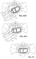
- FIGS. 16A, 16B and 16C are top views of the L5-S1 disc space, illustrating progressive reorientation of the implant within the disc space by repositioning of the pins on the tip of the introducer instrument in different sets of pin receiving holes on the implant;
- FIG. 17 is an enlarged top view of the L5-S1 disc space illustrating the implant in position within the disc space;
- FIG. 18A is a front elevation view of a shim for placement on the ipsilateral blade of the retractor instrument
- FIG. 18B is a side view of the shim of FIG. 18A ;
- FIG. 18C is a top view of the shim of FIGS. 4A and 4B ;
- FIG. 19A is a perspective view of an embodiment of an implant
- FIG. 19B is a side view of an embodiment of the implant of FIG. 19A ;
- FIG. 19C is an end view of an embodiment of the implant of FIG. 19A ;
- FIG. 20 is a top view of the L5-S1 disc space, illustrating orientation of the implant of FIG. 11A within a disc space;
- FIG. 21 is a perspective view of a portion of a retraction instrument with a pair of blades provided at a distal end;
- FIG. 22 is a top view of the retraction instrument of FIG. 21 , showing a mechanism for moving the retractor blades;
- FIG. 23A is a perspective view of a blade for use with a retraction instrument
- FIG. 23B is a rear view of the blade of FIG. 23A ;
- FIG. 23C is a top view of the blade of FIG. 23A .
- Embodiments of the invention are disclosed herein for accessing an intervertebral space, such as the L5-S1 space, and implanting a prosthetic disc implant within that space.
- the disclosed devices, methods and systems are suitable for use in a minimally invasive procedure for repairing degenerated or otherwise injured intervertebral discs.
- the method generally includes initially accessing the intervertebral space using a retroperitoneal lateral approach. Then, with a finger-directed dilator or other suitable instrument, the distal retroperitoneum is swept anteriorly to expose an eventual channel to a direct approach to L5-S1.
- the direct approach to L5-S1 is anterior to the anterior superior iliac spine, or between the anterior superior iliac spine and the anterior inferior iliac spine.
- An incision is then made to open this channel, and blunt dilators are directed in an oblique direction directly to the mid-anterior aspect of L5-S1, for example between the 10 o'clock and 2 o'clock position. Fluoroscopic guidance may be used in accordance with known techniques to assist in advancing and positioning the dilators.
- the blades of the retractor are translucent so that the retracted contents can be seen through the blades.
- the blades are shaped so that the curvature of the retractor blades conforms to the unique shape of the anatomy for the approach described herein, and is particularly suitable for use in this portion of the spine.
- the ipsilateral blade may be shorter than the contralateral blade, and the ipsilateral blade may be more arcuate with a steeper curve as compared to the less curved, straighter contralateral blade.
- the blades can accommodate a xenon light source for visualization in the cavity.
- the retractor blades are positioned below the iliac bifurcation between the right and left iliac vessels.
- the retractor blades are moved apart to increase exposure of the anterior vertebral column.
- a docking shim that is angled away from the ipsilateral blade and toward the disk space is placed in the intervertebral space to secure the retractor in position and maintain distraction of the vertebral bodies. If the small middle sacral artery is viewable in the midline, the surgeon may choose to ligate or electrocauterize this small vessel.
- the procedure provides a relatively large window within which a discectomy and reconstruction can be carried out.
- the tools used for the discectomy may be slightly angled (relative to tools used for existing techniques) to maximize disc removal from an oblique direction.
- Trial spacers and final disc implants have a unique design suited to the trajectory of the implantation, as described in greater detail below. Radiopaque markers may be included on the trial spacers and implants (for example at its corners) to enable the structures to be visualized under fluoroscopy.
- One or more trial spacers are then introduced into the evacuated disc space to help select an appropriate size implant.
- the initial insertion trajectory is oblique, resulting in diagonal entry of the trial spacer into disc space with impaction of the contralateral face of the implant or trial spacer to the far lateral aspect of the apophyseal rings (for example of L5-S1).
- the angle of impaction is then reoriented so that the portion of the trial spacer or implant that is present in the more anterior portion of the intervertebral space is impacted posteriorly on the apophyseal ring by using the contralateral side as a swivel point.
- final seating of the implant or trial spacer is achieved.
- retraction is slowly released by allowing the retraction blades to move toward one another to check for any residual bleeding.
- the retractor is then slowly removed so that the skin closure of the percutaneous incision can be carried out.
- a patient 20 is placed in a direct right lateral decubitis position with the patient's right side down on an operating table 22 and the left side up.
- a bolster pillow 24 is placed at the waist of patient 20 to bend the body at that point, which elevates and tilts the pelvis 26 of patient 20 .
- Pelvis 26 is schematically shown in FIGS. 1, 5A and 5B to include an ileum 28 , with an iliac crest 30 , anterior superior iliac spine 32 , and anterior inferior iliac spine 34 .
- a notch 36 ( FIGS. 5A and 5B ) is formed between the superior and inferior iliac spines 32 , 34 .
- the spinal anatomy is schematically illustrated in FIG.
- FIG. 1A wherein the sacrum 38 is shown connected to the L5 vertebra 40 . Higher levels of lumbar and thoracic vertebrae are shown superior to the L5 disc.
- the anatomy of the L5 vertebra is illustrated in more detail in FIG. 1B , wherein the vertebra includes an anterior vertebral body 42 and a posterior vertebral arch 44 that cooperatively define spinal foramen 46 .
- Vertebral body 42 includes a circumferential apophyseal ring 48
- vertebral arch 44 includes a spinous process 50 , right transverse process 52 and left transverse process 54 .
- Positions around vertebral body 42 can be designated arbitrarily by hours of the clock, with anterior-most position 56 designated the twelve o'clock position.
- an anterior face of vertebral body 42 is designated herein as the face 58 that extends from about the ten o'clock position 60 to the two o'clock position 62 .
- the axis of the vertebral column is located generally at the center of vertebral body 42 .
- FIG. 1C the anatomic planes of the body in the standard anatomical position are shown in FIG. 1C .
- “superior” means closer to the head
- “posterior” means closer to the posterior surface of the body
- anterior surface of the body means closer to the anterior surface of the body
- cephalad means toward the head
- cephalad means toward the head
- cephalad means toward the feet.
- the anatomic reference planes in FIG. 1C are the “coronal plane” that separates the body into anterior and posterior halves, and the “median plane” that separates the body into right and left parts.
- a transverse plane is shown, which is any plane that is perpendicular to the coronal and median planes; multiple transverse planes exist at different levels of the body.
- the “noon” position is on the front of the body along the A-P (anterior-posterior) line at which the median plane intersects a transverse plane.
- the three and six o'clock positions are along the L-M (lateral-medial) line at the intersection of the transverse and coronal planes.
- an “oblique plane” is any plane that is at an angle (not within or parallel) to any one of the coronal, median or transverse planes.
- an operative corridor is “oblique” if it is an oblique plane.
- An oblique angle can lie in one of the illustrated coronal, median or transverse planes, be parallel to one or two of those planes, or be outside of (and not parallel) to all three of them.
- an oblique pathway P 1 to an intervertebral space can extend in a transverse plane at a non-zero angle to the median plane.
- an oblique pathway P 2 can extend at a non-zero angle to the transverse, coronal and median planes.
- FIGS. 5A and 5B shows the aortic bifurcation 64 into the right and left common iliac arteries 66 , 68 , each of which divides into an external iliac artery 66 a , 68 a and an internal iliac artery 66 b , 68 b .
- Accompanying common iliac veins 67 , 69 are also shown in FIG. 5A .
- the descending aortic artery, bifurcation 64 , and the bifurcated iliac vessels are at the anterior face of the vertebral bodies, and have complicated surgical approaches that attempt to access the anterior vertebral body to repair a damaged spinal disc.
- the L5-S1 intervertebral space 70 is shown in FIG. 5A without retraction of the iliac vessels, and in FIG. 5B with retraction of the iliac vessels to expose L5-S1 intervertebral space 70 .
- FIGS. 2A and 3A Additional pertinent perispinal anatomy is shown in FIGS. 2A and 3A , wherein right and left common iliac arteries 66 , 68 and veins 67 , 69 are shown in their normal anatomic position on the anterior aspect of the spine.
- the nucleus pulposus 72 of the L5-S1 intervertebral disc is illustrated, as are the right and left psoas muscles 74 , 76 , the right and left erector spinae muscles 78 , 80 and the right and left transversospinalis muscles 82 , 84 .
- the peritoneum 86 which is normally adjacent and adherent to the retroperitoneal structures, is shown in FIGS. 2A and 3A after it has been moved anteriorly and separated from the retroperitoneal structures on the right side of the body to clear an operative pathway to the L5-S1 intervertebral space.
- an initial incision 90 ( FIG. 1 ) is made at this point in the mid-axillary line, as in a standard retroperitoneal approach.
- blunt finger dissection is directed caudally in the retroperitoneal plane to connect to a point that is parallel the L5-S1 disc space, just anterior to ileum 28 .
- the surgeon's finger 94 sweeps peritoneum 86 anteriorly, moving it away from the ileum 28 and the retroperitoneal structures in the right side of the abdominal cavity.
- a second skin incision 92 ( FIGS. 1A and 2A ) is then made inferior to first incision 90 .
- Second incision 92 is anterior to first incision 90 , between the anterior axially line and the sheath of the rectus abdominis muscle, and is approximately 3-5 cm in length. Second incision 92 is made at the level of the L5-S1 disc space, which is determined fluoroscopically prior to making the incision.
- FIG. 2B illustrates an initial access assembly 100 for accessing the targeted intervertebral space, such as the L5-S1 intervertebral space. Although a particular device and method are described for accessing the L5-S1 intervertebral space, the disclosed invention is not limited to use of this particular device and method.
- Illustrated access assembly 100 includes a K-wire 102 , an initial dilating cannula 104 with handle 106 , and a split-dilator 108 housed within the initial dilating cannula 104 .
- the entire assembly 100 is advanced under fluoroscopic guidance through the tissue towards the surgical target site (i.e. annulus). This may be accomplished using a nerve detection and/or direction device as described in U.S. Pat. No. 7,207,949, although the nerve detection capability is not necessary.
- Initial dilating assembly 100 is advanced until the distal ends of split-dilator 108 and initial dilator 104 are positioned within the disc space.
- the initial dilator 104 and handle 106 are then removed ( FIG. 2C ) to leave split-dilator 108 and K-wire 102 in place.
- Split-dilator 108 is thereafter split such that the respective halves 108 a , 108 b are separated from one another to distract tissue in a generally cephalad-caudal fashion relative to the target site as described in more detail in U.S. Pat. No. 7,207,949.
- Split dilator 108 may thereafter be relaxed (allowing the dilator halves 108 a , 108 b to come together) and rotated approximately 90 degrees such that the dilator halves 108 a , 108 b are disposed in a transverse anatomic plane. Once rotated in this manner, the dilator halves 108 a , 108 b are again separated to distract tissue in the transverse plane.
- Each dilator half 108 a , 108 b may be provided with one or more electrodes (preferably at their distal regions) equipped for use with a nerve surveillance system, such as, by way of example, the Neuro Vision System, although the nerve monitors are optional.
- Progressively larger dilators may be used to further establish the operative pathway.
- the dilators are labeled with depth markings to help assure insertion of the successive dilators to the appropriate depth.
- the dilators are introduced obliquely into the body along a diagonal pathway from incision 92 to the anterior aspect of the spine to enter the intervertebral space between the twelve o'clock and two o'clock positions.
- the particularly illustrated pathway is generally in a transverse plane at the level of L5-S1, but at an angle to (and between) the coronal and median planes (for example in the direction of the pathway P 1 in FIG. 1C ).
- the pathway can also be at an angle to the transverse plane as well (for example, at the same angle as pathway P 2 in FIG. 1C ).
- the dilator pathway helps determine the eventual operative corridor that is established by placement of retraction instrument 110 .
- the retraction instrument 110 can itself establish the operative corridor without the initial use of the dilators.
- Retraction instrument 110 includes a proximal handle portion 112 and a distal retractor blade portion 114 that includes opposing contralateral retraction arm 116 and ipsilateral retraction arm 118 , which respectively carry a terminal contralateral retraction blade 120 and ipsilateral retraction blade 122 .
- Each of blades 120 , 122 is curved longitudinally away from the axis of elongated retractor instrument 110 ( FIG. 3A ), and is additionally curved radially ( FIG. 3B ). As shown in FIGS.
- ipsilateral retraction blade 122 is shorter and has a greater cross-sectional (radial) curvature than contralateral retraction blade 120 .
- ipsilateral blade 122 has a greater longitudinal curvature than contralateral blade 120 .
- a pair of angled extension members 117 , 119 can extend from handle portion 112 to improve the access angle provided by the retractor instrument.
- Conventional retraction instruments are not well suited for approaches that are not directly lateral to an implantation site.
- the increased distance from the handle to the blades and the change in angle provided by extension members 117 , 119 improve access to the implantation sites for the methods described herein.
- extension members 117 , 119 can extend from handle portion 112 such that they are substantially parallel to one another and form an angle of between about 45 and 80 degrees from a plane formed by a surface of handle portion 112 to which extension members abut and from which extension members extend. As shown in FIG. 22 , extension member 119 is preferably shorter than extension member 117 . If desired, a central angled extension member 121 can be provided between extension members 117 , 119 to receive another blade member. Arms 116 , 118 ( FIG. 3A ) are coupled to extension members 117 , 119 , respectively.
- Arms 116 , 118 and their respective retraction blades 120 , 122 can be moved toward and away from one another by the movement of handles 124 , 126 , generally as shown in U.S. Pat. No. 7,207,949.
- handles 124 , 126 are coupled to a gear mechanism that converts the movement of the handles toward each other into linear movement of retraction arms 116 , 118 away from one another to widen the distance between those arms without rotating them.
- the distance between handles 124 , 126 can be adjusted and fixed by rotation of knobs 134 , 136 .
- the retraction instrument 110 is placed in cannulated fashion over the dilators with the shorter ipsilateral arm/retraction blade on the ipsilateral side of the operative corridor.
- Retraction instrument 110 is slightly opened by moving handles 124 , 126 toward one another so that opposing retraction arms 116 , 118 move farther apart without rotation of the retraction arms.
- a standard xenon light source is carried by the instrument, and it is used for visualization of the anatomy at the distal tip of the instrument to position the retractor blades between the bifurcation of the right and left common iliac arteries and veins.
- the foot of ipsilateral blade 122 is placed beneath the ipsilateral vasculature (the right side for the approach illustrated in FIG.
- Handles 124 , 126 are then moved closer together and fixed in position to move retraction arms 116 , 118 away from one another and create surgical exposure of the anterior spine by moving ipsilateral vessels 66 , 67 posteriorly and laterally with ipsilateral blade 122 , and by moving contralateral vessels 68 , 69 anteriorly and laterally with contralateral blade 120 .
- Handles 124 , 126 can be moved and fixed in different positions by rotation of knobs 134 , 136 .
- FIGS. 5A and 5B illustrate retraction of the iliac vasculature to expose the L5-S1 intervertebral space; FIG. 5B also shows the trajectory along which retraction instrument 110 may be advanced.
- FIG. 5A shows the iliac vasculature running along the anterior spine near the front of the L5-S1 intervertebral space 70 .
- FIG. 5B illustrates the iliac vessels retracted away from the anterior face of the spine by the retractor instrument 110 (not shown).
- a trajectory along which retractor instrument 110 may be introduced is shown by arrow 128 in FIG. 5B .
- the illustrated trajectory is from anterolateral incision 92 through the region of notch 36 between anterior superior iliac spine 32 and anterior inferior iliac spine 34 . This trajectory contrasts with trajectory 130 (dotted line in FIG. 5B ) taken by prior minimally invasive direct lateral surgeries for the L4-L5 disc space from the axillary line.
- a shim 132 ( FIGS. 3A and 4A, 4B, 4C ) is inserted along the ipsilateral blade and advanced to position shim 132 within the anterolateral region of the L5-S1 disc space.
- blades 120 , 122 can each be provided with a slot 133 for receiving a shim 132 .
- FIG. 22 illustrates blade 122 with a shim 132 in slot 133
- blade 120 of FIG. 22 is shown without a shim or other structure positioned within its respective slot 133 .
- Shim 132 is an elongated plate with a substantially planar proximal portion 130 a and a curved distal portion 130 b .
- the curved distal portion 130 b also tapers to a pointed distal tip 131 that is designed for introduction into an intervertebral space.
- the substantially planar proximal portion of shim 132 has a height h greater than its thickness t to minimize obstruction of access to the disc space when the shim is in place, and the height of the shim narrows anteriorly to pointed distal tip 131 .
- Shim 132 further has a reversed curvature, in that its distal portion 130 b is curved away from ipsilateral retraction blade 122 and toward contralateral retraction blade 120 .
- shim 132 can be substantially straight along its entire length. Shim 132 is attached to ipsilateral blade 120 to help lock retractor instrument 110 in position until removal of the instrument is desired, and distracts the adjacent vertebral bodies (such as L5 and S1) to restore disc height. Shim 132 can be coupled to ipsilateral blade 120 and/or contralateral blade 122 in a variety of manners.
- shim 132 comprises a projecting portion 135 that projects outward from a surface of shim 132 .
- Projecting portion 135 can be a spring-loaded member that is biased outward from the surface of shim 132 .
- shim 132 can be positioned in a slot 133 and secured thereto to the respective blade (e.g., blade 122 in FIG. 23C ).
- a plurality of spaced detents or openings 137 can extend along the length of a rear side 139 of blade 122 to receive projecting portion 135 and secure shim 132 to blade 122 .
- shim 132 is restricted from moving relative to blade 122 .
- projecting portion 135 can be pushed inward towards the surface of shim 132 , moving projecting portion 135 out of detent 137 and releasing shim 132 from blade 122 .
- shim 132 can be moved into another position along blade 122 by pushing or otherwise directing shim 132 downward along the length of blade 122 . This process can be repeated until shim 132 is secured to blade 122 in a desired position.
- Shim 132 also rigidly couples ipsilateral retractor blade 122 in fixed relation relative to the vertebral bodies, and helps ensure that surgical instruments employed within the operative corridor are not advanced outside the operative corridor, thereby avoiding inadvertent contact with the exiting nerve roots and vasculature during the surgery. Once the operative corridor is established, any of a variety of surgical instruments, devices, or implants may be passed through and/or manipulated within the operative corridor depending upon the given surgical procedure.
- Superior and inferior soft tissue retractors may also be placed as needed for retraction for any creeping retroperitoneal contents to allow creation of a box-type approach to the L5-S1 disc space. Discectomy is than carried out in a conventional fashion to evacuate as much of the disc and interspace contents as possible.
- the handle portion 112 may be coupled to any number of mechanisms for rigidly registering it in fixed relation to the operative site, such as through the use of an articulating arm mounted to the operating table 22 .
- trial implants are introduced into the L5-S1 disc space 70 to select an appropriate size final implant, and a final implant is then introduced into the disc space.
- FIGS. 6-9 illustrate an introducer instrument 140 for introducing implants into the disc space.
- Instrument 140 includes a rigid sheath 142 ( FIGS. 6-7 ) that is sufficiently long to reach the L5-S1 disc space 70 .
- a longitudinal axis 144 of sheath 142 is illustrated by a dashed line.
- Instrument 140 is provided with a proximal handle 146 that is coupled to a rotatable shaft 147 ( FIG. 8 ) inside a ridged collar 148 ( FIG. 7 ) so that shaft 147 can be rotated within sheath 142 by rotating handle 146 as collar 148 is grasped by the surgeon's hand to maintain collar 148 stationary. As shown in FIG.
- an externally threaded rod 150 projects from a cylindrical distal tip 152 of sheath 142 along longitudinal axis 144 on sheath 142 .
- a pair of small coupling pins 154 , 156 which are smaller than threaded rod 150 , project from distal tip 152 on either side of rod 150 in a fixed spaced alignment generally along a common plane that bisects shaft 142 along its axis 144 .
- Coupling pins 154 , 156 are substantially shorter and of much smaller diameter than the threaded rod 150 . For example, coupling pins are less than 25% or even 10% of the diameter and length of threaded rod 150 projecting from the tip 152 of instrument 140 .
- threaded rod 150 is connected to rotatable shaft 147 by a reduced diameter step-down extension 158 that projects out of distal tip 152 of sheath 142 to provide a gap between threaded rod 150 and the face 160 of distal tip 152 .
- Distal tip 152 (and pins 154 , 156 that it carries) can be selectively advanced toward and retracted from implant 172 in a pathway generally parallel to longitudinal axis 144 by rotating handle 146 .
- handle 146 rotates counterclockwise, it drives shaft 147 to turn threaded rod 150 and loosen the connection between rod 150 and a threaded opening in the implant.
- pins 154 , 156 have a much shorter axial length than threaded rod 150 , only slight loosening of the threaded rod is required to disengage pins 154 , 156 from the implant. Once pins 154 , 156 are disengaged from the implant, they can be repositioned in another set of openings on the implant to change the angle between instrument 140 and the implant. Handle 146 is then rotated clockwise to tighten the pins in their new openings to fix the new angular relationship between instrument 140 and the implant.
- Threaded rod 150 and coupling pins 154 , 156 form an example of a docking element of introducer instrument 140 .
- the docking element selectively docks with an interface element 170 of an implant 172 , as shown in FIG. 9 .
- the docking element docks at a plurality of positions with interface element 170 to selectively alter an angle between implant 172 and introducer instrument 140 .
- Implant 172 has a pivot axis 174 around which implant 172 may be pivoted relative to longitudinal axis 144 of instrument 140 .
- FIGS. 10A and 10B An example of an implant 172 is shown in greater detail in FIGS. 10A and 10B , where implant 172 has a top bearing face 176 , a bottom bearing face 178 , a front face 180 , a rear face 182 , an ipsilateral face 184 and a contralateral face 186 .
- a rotation pin 188 extends between top and bottom faces 176 , 178 and rotates relative to implant 172 ; pivot axis 174 of implant 172 extends along the axis of rotation pin 188 .
- Interface element 170 FIGS.
- Interface element 170 therefore includes spaced docking holes that extend partially circumferentially around pivot axis 174 so that selected pairs of docking holes are positioned to mate with the docking element of introducer instrument 140 .
- introducer instrument 140 is secured to an implant 172 by threading rod 150 into opening 191 of rotation pin 188 by rotating handle 146 to turn shaft 147 within sheath 142 .
- Handle 146 is rotated until implant 172 is tightly secured to distal tip 152 and pins 154 , 156 are aligned with and inserted within a pair of the upper and lower aligned docking holes.
- the angular relationship between instrument 140 and implant 172 can be altered by slightly unscrewing threaded rod 150 from threaded opening 191 . This action moves face 160 of distal tip 152 sufficiently out of engagement with interface element 170 to disengage pins 154 , 156 from a first set of docking holes without completely disconnecting instrument 140 from implant 172 .
- the implant 172 and instrument 140 can then pivot relative to one another until sheath 142 is again advanced to engage coupling pins 152 , 154 with a new pair of docking holes by rotating handle 146 to once again securely engage instrument 140 to implant 172 , so that the implant is fixed at a new angular relationship with the instrument.
- angular relationship between instrument 140 and implant 172 can be selectively altered
- many other means for varying this angular relationship to pivot the implant are contemplated.
- rotation of handle 146 can actuate a gear that pivots implant 172
- handle rotation can actuate a cam that selectively moves pins 154 , 156 to selectively engage and disengage them from interface element 170 .
- the tip of instrument 140 can fit into a slot within implant 172 to pivot the implant as instrument 140 is moved from the contralateral to the ipsilateral arm of the retractor instrument.
- a universal joint is provided between the instrument 140 and implant 172 to selectively pivot the implant relative to the instrument. Different numbers and arrangements of the pins can also be provided.
- Electronic devices can also be used that rotate the implant in the plane of the disc space while maintaining the instrument within the operative pathway defined between the retraction blades of instrument 140 .
- implant 172 Additional features of implant 172 are shown in detail in FIGS. 10 and 11 to illustrate details that make the implant particularly suitable for insertion and progressive pivoting of the implant within the L5-S1 disc space, as described in greater detail below.
- the implant tapers in height from the height h 1 of front face 180 to height h 2 of rear face 182 , and is elongated in a direction transverse to the direction of tapering height. Hence front face 180 and rear face 182 are longer than ipsilateral and contralateral faces 184 , 186 .
- the implant material is made of a generally compressible or elastomeric material.
- Front face 180 is generally convex, ipsilateral face 184 includes interface element 170 , rear face 176 is generally flat, and contralateral face 186 is rounded at its front and rear edges to minimize impact damage to spinal structures as the implant is introduced into the disc space and pivoted into position.
- Implant 172 is also partially hollow and may have ipsilateral and contralateral windows 200 , 202 extending between top and bottom faces 176 , 178 .
- the windows are formed by an internal divider wall 204 that extends from the front to rear of implant 172 and substantially bisects the implant into ipsilateral and contralateral halves.
- ipsilateral window 200 is smaller than contralateral window 202 because a portion of the ipsilateral half of implant 172 is occupied by rotation pin 188 and the structure that supports it.
- the windows 200 , 202 provide communication between the open bottom and top faces of the implant to promote ingrowth of tissue within and through implant 172 .
- Top and bottom faces 176 , 178 are provided with protuberances 206 that also help promote bone growth into implant 172 .
- the protuberances may take a variety of shapes, but the illustrated frustopyramidal protuberances 206 are believed to be particularly suitable for this purpose.
- trial spacers are also provided to help assess the size of the disc space once the disc space contents have been evacuated but before the final implant is advanced into the disc space.
- FIGS. 11A, 11B, and 11C illustrate another embodiment of an implant 272 .
- FIGS. 11A-C use reference numbers with the same two final digits for elements that are generally similar to elements identified in FIGS. 10A and 10B .
- implant 272 has a top bearing face 276 , a bottom bearing face 278 , a front face 280 , a rear face 282 , an ipsilateral face 284 and a contralateral face 286 .
- a rotation pin 288 extends between top and bottom faces 276 , 278 and rotates relative to implant 272 .
- Pivot axis 274 of implant 272 extends along the axis of rotation pin 288 .
- An interface element 270 ( FIGS. 11B and 11C ) has a recessed slot 290 between top and bottom faces 276 , 278 that provides access to the side of rotation pin 288 in which an internally threaded opening 291 is provided which has threads that are complementary to the external threads of rod 150 of introducer instrument 140 .
- An upper arcuate lip 292 and lower arcuate lip 294 form slot 290 cooperatively therebetween.
- FIG. 11B is shown without pin 288 fitted or received in implant 272 .
- Lips 292 , 294 of interface element 270 can have a series of spaced docking holes such as that shown in FIGS. 10A and 10B .
- lips 292 , 294 can be formed without such docking holes.
- the introducer instrument can be shaped to contact a portion of the upper and/or lower curved faces of lips 292 , 294 , thereby forming a frictional fit between the convex face of implant 272 and a concave face 160 of the introducer instrument 140 .
- introducer instrument 140 can be secured to implant 272 by threading rod 150 into opening 291 of rotation pin 288 by rotating handle 146 to turn shaft 147 within sheath 142 .
- implant 272 When handle 146 is rotated a sufficient amount, implant 272 will be tightly secured to face 160 of distal tip 152 .
- the angular relationship between instrument 140 and implant 272 can be altered by slightly unscrewing threaded rod 150 from threaded opening 291 . This action moves face 160 of distal tip 152 sufficiently out of engagement of the frictional fit with interface element 270 (or other contacting portion of a surface of implant 272 ).
- Implant 272 and instrument 140 can then pivot relative to one another until sheath 142 is again advanced to engage the instrument 140 and implant 272 in a frictional fit that is tight enough to restrict relative movement of the instrument 140 and implant 272 .
- implant 272 can be constructed so that it is substantially the same thickness (height) along its length ( FIG. 11B ), while at the same time varying in thickness (height) along its width ( FIG. 11C ).
- the thickness (height) of implant 272 can vary from a first larger height to a second smaller height to facilitate the implantation of the device in the patient.
- implant 272 can be provided with protuberances 306 that help promote bone growth into implant 172 .
- protuberances can take a variety of shapes.
- implant 272 can be at least partially hollow and can have one or more windows (e.g., windows 300 , 302 ). Windows 300 , 302 can provide the same benefits as windows 200 , 202 in the previous embodiment, which is to provide communication between the open bottom and top faces of the implant to promote ingrowth of tissue within and through implant 272 .
- Implant 272 can also have one or more openings 303 that extend through a side wall of the implant to further promote ingrowth of tissue and to facilitate access to internal areas of implant 272 (e.g., access to one or both of windows 300 , 302 ) when implant 272 is implanted in the body.
- Windows 300 , 302 can extend between top and bottom faces 276 , 278 as shown in FIG. 11A .
- the windows can be formed by an internal divider wall 304 that substantially bisect the implant into two halves.
- divider wall 304 preferably extends diagonally across implant 272 from an area adjacent or near the pin 288 to an area at or near contralateral face 286 .
- diagonal wall 304 can provide structural strength to the implant in the general direction of the force that will be applied to implant 272 during implantation.
- divider wall 304 is located substantially in-line with the instrument 140 .
- FIG. 12 illustrates another version of an implant 220 .
- This implant is similar to that shown in FIGS. 10-11 , except it is substantially rectangular in shape instead of polygonal, and it has a rotation pin 222 with a pivot axis 224 that extends between a front and rear face of implant 220 .
- Rotation pin 222 includes an opening 226 (e.g., a threaded opening) for receiving a threaded distal end of introducer instrument 140 .
- implant 220 can be secured to threading rod 150 by positioning rod 150 into opening 226 and rotating handle 146 to turn shaft 147 and tighten the distal end of the instrument (e.g., face 160 ) to a facing surface of implant 220 .
- implant 220 is therefore suitable for pivoting up and down with respect to introducer instrument 140 instead of from side-to-side as with implant 172 . It may also have varied dimensions medial to lateral as described for implant 172 , although other embodiments do not taper and are of uniform height.
- the embodiment of the implant shown in FIG. 12 is generally used in surgeries superior to the L5-S1 space, for example in the L4-L5 space or the L3-L4 space.
- the implant can be delivered to the implantation site from a location superior to iliac crest 30 and pivoted vertically into the desired position at the implantation site.
- implant 220 can be provided with one or more windows 228 , 230 and a plurality of protrusions 232 to promote the ingrowth of tissue.
- Implant 220 can also be provided with a plurality of docking holes 234 to help lock or secure implant 220 to a distal end of instrument 140 .
- implant 220 can be secured to the instrument 140 via a frictional fit or other similar mechanism.
- FIGS. 19A, 19B, and 19C illustrate another embodiment of an implant that can pivot up and down (e.g., vertically), in a manner similar to that shown in FIG. 12 .
- Implant 320 is configured to receive a rotation pin (not shown) in a recess 322 between a top surface 324 and a bottom surface 326 of implant 320 .
- implant 320 can include a plurality of windows 330 , 332 separated by a divider wall 334 .
- openings 336 can be formed in the side of the implant as shown in FIGS. 19A and 19B .
- a trial spacer 210 is attached to introducer instrument 140 and advanced into the L5-S1 disc space as shown in FIG. 13 .
- the trial spacer is generally similar to implant 174 , except it does not have the protuberances projecting from its top and bottom faces.
- the spacer is directly laterally attached to instrument 110 .
- the direct lateral attachment is shown in FIG. 13 , wherein the longitudinal axis of sheath 142 is generally parallel to flat rear face 182 of implant 210 . Because of the anterolateral operative pathway to the disc space, trial implant 210 moves along a generally oblique or diagonal pathway into the disc space.
- the “oblique” pathway is one that travels diagonally within the body, for example in an oblique anatomic plane.
- the oblique pathway may be a diagonal pathway, for example between 15 and 45 or 60 degrees to a coronal plane of the body.
- the oblique pathway is shown at an angle ⁇ of about 30 degrees to coronal plane 212 ( FIG. 13 ).
- the oblique pathway may be either in a transverse plane of the body, or above or below a transverse plane (for example between 15 and 45 or 60 degrees to a transverse plane of the body).
- fluoroscopy is used to detect the level of the target disc space (such as L5-S1) so that the instrument, spacer and implant can be introduced diagonally in the body, but generally in the plane of the L5-S1 disc space.
- target disc space such as L5-S1
- contralateral face 186 impacts the posterior contralateral aspect of the disc space.
- the rounded edges of contralateral face 186 help avoid damage to the structures which the contralateral face 186 of the trial spacer encounters.
- the trial spacer is then progressively reoriented from its diagonal orientation in the disc space ( FIG. 14A ) to a generally medial-lateral orientation ( FIG.
- sheath 142 moves from a first position abutting contralateral retractor blade 120 ( FIG. 14A ) to a second position abutting ipsilateral blade 122 ( FIG. 14C ).
- Trial spacers of different sizes may be introduced into the disc space and pivoted from the diagonal to the medial-lateral orientation until a trial spacer of the appropriate size and height is found.
- Introducer instrument 140 is detached from trial spacer 210 by rotating handle to unscrew threaded 150 from the internally threaded opening of trial spacer 210 to secure different trial spacers until the correct one is found.
- the trial spacer is then withdrawn from the disc space and detached from introducer instrument 140 , and the final implant 172 is directly laterally attached to distal tip 152 of introducer instrument 140 (as illustrated in FIG. 15 ) by rotating handle 146 to screw the threaded rod at the tip of instrument 140 into the internally threaded hole on the implant.
- FIG. 16A illustrates the diagonal introduction of implant 172 into the disc space along the same pathway already described for trial spacer 210 .
- the implant enters the disc space with its flat rear face 182 at an angle of about 15-45 degrees (for example 30 degrees) to a coronal plane of the body.
- the implant is then progressively reoriented by retracting sheath 142 , pivoting implant 172 within the disc space, and advancing sheath 142 to reengage coupling pins 154 , 156 within a new set of docking holes to hold implant 172 in the intermediate orientation shown in FIG.
- Implant 172 can then be further reoriented in this fashion until sheath 142 contacts ipsilateral arm 118 of retractor instrument 110 ( FIG. 16C ). Once implant 172 can not be reoriented any further using the instrument, handle 146 is rotated to completely disengage introducer instrument 140 from implant 172 . Instrument 140 is then withdrawn from retractor instrument 110 .
- Additional positioning of implant 172 can be achieved by pushing it with the tip of instrument 140 , or with other elongated instruments introduced through retractor instrument 110 .
- Retractor instrument 110 can then be removed from the body by moving arms 116 , 118 toward one another to reduce the width of instrument 110 then withdrawing it from the body. Normal closure of the surgical incisions on the body surface is then carried out.
- FIG. 20 illustrates implant 272 secured to instrument 140 and being delivered to an implantation site.
- the method of delivering implant 272 is substantially the same as the method of delivering implant 172 , which is described above and shown in FIGS. 15-17 .
- Implant 272 is desirably secured to the distal end of instrument 140 so that divider wall 304 is generally in-line with axis 350 of instrument 140 . In this manner, implant 272 can exhibit increased strength to ensure that it can withstand the impaction force, which is generally applied along the axis 350 to deliver implant 272 to the desired location in the body.
- the implants described herein can be coated with and/or impregnated with various elements to promote bone in-growth.
- stem cells can be delivered along with the implant (either delivered into openings in the implant or coated thereon) to improve and facilitate bone in-growth.
Landscapes
- Health & Medical Sciences (AREA)
- Engineering & Computer Science (AREA)
- Biomedical Technology (AREA)
- Orthopedic Medicine & Surgery (AREA)
- Neurology (AREA)
- Life Sciences & Earth Sciences (AREA)
- Transplantation (AREA)
- General Health & Medical Sciences (AREA)
- Veterinary Medicine (AREA)
- Heart & Thoracic Surgery (AREA)
- Public Health (AREA)
- Animal Behavior & Ethology (AREA)
- Cardiology (AREA)
- Vascular Medicine (AREA)
- Oral & Maxillofacial Surgery (AREA)
- Surgery (AREA)
- Physical Education & Sports Medicine (AREA)
- Nuclear Medicine, Radiotherapy & Molecular Imaging (AREA)
- Medical Informatics (AREA)
- Molecular Biology (AREA)
- Prostheses (AREA)
- Surgical Instruments (AREA)
Abstract
Description
Claims (20)
Priority Applications (6)
| Application Number | Priority Date | Filing Date | Title |
|---|---|---|---|
| US16/149,108 US10959860B2 (en) | 2008-12-26 | 2018-10-01 | Method of retroperitoneal lateral insertion of spinal implants |
| US17/209,874 US11969359B2 (en) | 2008-12-26 | 2021-03-23 | Method of retroperitoneal lateral insertion of spinal implants |
| US17/990,254 US12383411B2 (en) | 2008-12-26 | 2022-11-18 | Spinal surgery methods and devices |
| US18/624,309 US20240245530A1 (en) | 2008-12-26 | 2024-04-02 | Spinal surgery methods and devices |
| US19/257,087 US12465499B2 (en) | 2008-12-26 | 2025-07-01 | Spine surgery methods and devices |
| US19/359,479 US20260041567A1 (en) | 2008-12-26 | 2025-10-15 | Spine surgery methods and devices |
Applications Claiming Priority (7)
| Application Number | Priority Date | Filing Date | Title |
|---|---|---|---|
| US14092608P | 2008-12-26 | 2008-12-26 | |
| US17831509P | 2009-05-14 | 2009-05-14 | |
| PCT/US2009/069476 WO2010075555A2 (en) | 2008-12-26 | 2009-12-23 | Minimally-invasive retroperitoneal lateral approach for spinal surgery |
| US13/239,014 US9451940B2 (en) | 2008-12-26 | 2011-09-21 | Method of retroperitoneal lateral insertion of spinal implants |
| US201113133909A | 2011-09-23 | 2011-09-23 | |
| US15/235,957 US10085854B2 (en) | 2008-12-26 | 2016-08-12 | Method of retroperitoneal lateral insertion of spinal implants |
| US16/149,108 US10959860B2 (en) | 2008-12-26 | 2018-10-01 | Method of retroperitoneal lateral insertion of spinal implants |
Related Parent Applications (1)
| Application Number | Title | Priority Date | Filing Date |
|---|---|---|---|
| US15/235,957 Continuation US10085854B2 (en) | 2008-12-26 | 2016-08-12 | Method of retroperitoneal lateral insertion of spinal implants |
Related Child Applications (2)
| Application Number | Title | Priority Date | Filing Date |
|---|---|---|---|
| US17/209,874 Division US11969359B2 (en) | 2008-12-26 | 2021-03-23 | Method of retroperitoneal lateral insertion of spinal implants |
| US17/209,874 Continuation US11969359B2 (en) | 2008-12-26 | 2021-03-23 | Method of retroperitoneal lateral insertion of spinal implants |
Publications (2)
| Publication Number | Publication Date |
|---|---|
| US20190105179A1 US20190105179A1 (en) | 2019-04-11 |
| US10959860B2 true US10959860B2 (en) | 2021-03-30 |
Family
ID=42288436
Family Applications (12)
| Application Number | Title | Priority Date | Filing Date |
|---|---|---|---|
| US13/133,909 Abandoned US20120035730A1 (en) | 2008-12-26 | 2009-12-23 | Minimally-invasive retroperitoneal lateral approach for spinal surgery |
| US13/239,014 Active US9451940B2 (en) | 2008-12-26 | 2011-09-21 | Method of retroperitoneal lateral insertion of spinal implants |
| US13/239,042 Abandoned US20120010716A1 (en) | 2008-12-26 | 2011-09-21 | Insertion device for use during retroperitoneal lateral insertion of spinal implants |
| US13/239,024 Abandoned US20120010472A1 (en) | 2008-12-26 | 2011-09-21 | Retractor for use during retroperitoneal lateral insertion of spinal implants |
| US13/239,053 Abandoned US20120010717A1 (en) | 2008-12-26 | 2011-09-21 | Spinal implant for use during retroperitoneal lateral insertion procedures |
| US15/235,957 Active 2030-01-26 US10085854B2 (en) | 2008-12-26 | 2016-08-12 | Method of retroperitoneal lateral insertion of spinal implants |
| US16/149,108 Active US10959860B2 (en) | 2008-12-26 | 2018-10-01 | Method of retroperitoneal lateral insertion of spinal implants |
| US17/209,874 Active 2031-01-28 US11969359B2 (en) | 2008-12-26 | 2021-03-23 | Method of retroperitoneal lateral insertion of spinal implants |
| US17/990,254 Active US12383411B2 (en) | 2008-12-26 | 2022-11-18 | Spinal surgery methods and devices |
| US18/624,309 Abandoned US20240245530A1 (en) | 2008-12-26 | 2024-04-02 | Spinal surgery methods and devices |
| US19/257,087 Active US12465499B2 (en) | 2008-12-26 | 2025-07-01 | Spine surgery methods and devices |
| US19/359,479 Pending US20260041567A1 (en) | 2008-12-26 | 2025-10-15 | Spine surgery methods and devices |
Family Applications Before (6)
| Application Number | Title | Priority Date | Filing Date |
|---|---|---|---|
| US13/133,909 Abandoned US20120035730A1 (en) | 2008-12-26 | 2009-12-23 | Minimally-invasive retroperitoneal lateral approach for spinal surgery |
| US13/239,014 Active US9451940B2 (en) | 2008-12-26 | 2011-09-21 | Method of retroperitoneal lateral insertion of spinal implants |
| US13/239,042 Abandoned US20120010716A1 (en) | 2008-12-26 | 2011-09-21 | Insertion device for use during retroperitoneal lateral insertion of spinal implants |
| US13/239,024 Abandoned US20120010472A1 (en) | 2008-12-26 | 2011-09-21 | Retractor for use during retroperitoneal lateral insertion of spinal implants |
| US13/239,053 Abandoned US20120010717A1 (en) | 2008-12-26 | 2011-09-21 | Spinal implant for use during retroperitoneal lateral insertion procedures |
| US15/235,957 Active 2030-01-26 US10085854B2 (en) | 2008-12-26 | 2016-08-12 | Method of retroperitoneal lateral insertion of spinal implants |
Family Applications After (5)
| Application Number | Title | Priority Date | Filing Date |
|---|---|---|---|
| US17/209,874 Active 2031-01-28 US11969359B2 (en) | 2008-12-26 | 2021-03-23 | Method of retroperitoneal lateral insertion of spinal implants |
| US17/990,254 Active US12383411B2 (en) | 2008-12-26 | 2022-11-18 | Spinal surgery methods and devices |
| US18/624,309 Abandoned US20240245530A1 (en) | 2008-12-26 | 2024-04-02 | Spinal surgery methods and devices |
| US19/257,087 Active US12465499B2 (en) | 2008-12-26 | 2025-07-01 | Spine surgery methods and devices |
| US19/359,479 Pending US20260041567A1 (en) | 2008-12-26 | 2025-10-15 | Spine surgery methods and devices |
Country Status (5)
| Country | Link |
|---|---|
| US (12) | US20120035730A1 (en) |
| EP (1) | EP2381871A4 (en) |
| AU (1) | AU2009329873A1 (en) |
| CA (1) | CA2750917A1 (en) |
| WO (1) | WO2010075555A2 (en) |
Cited By (1)
| Publication number | Priority date | Publication date | Assignee | Title |
|---|---|---|---|---|
| US11389151B2 (en) | 2019-11-22 | 2022-07-19 | Institute for Musculoskeletal Science and Education, Ltd. | Modular retractor system |
Families Citing this family (134)
| Publication number | Priority date | Publication date | Assignee | Title |
|---|---|---|---|---|
| WO2006058221A2 (en) | 2004-11-24 | 2006-06-01 | Abdou Samy M | Devices and methods for inter-vertebral orthopedic device placement |
| US20070162132A1 (en) | 2005-12-23 | 2007-07-12 | Dominique Messerli | Flexible elongated chain implant and method of supporting body tissue with same |
| US9345587B2 (en) | 2006-03-22 | 2016-05-24 | Beacon Biomedical, Llc | Pivotal lateral cage and method of insertion |
| US8034110B2 (en) | 2006-07-31 | 2011-10-11 | Depuy Spine, Inc. | Spinal fusion implant |
| WO2008070863A2 (en) | 2006-12-07 | 2008-06-12 | Interventional Spine, Inc. | Intervertebral implant |
| CN101909548B (en) | 2008-01-17 | 2014-07-30 | 斯恩蒂斯有限公司 | An expandable intervertebral implant and associated method of manufacturing the same |
| CN102036623A (en) | 2008-04-05 | 2011-04-27 | 斯恩蒂斯有限公司 | Expandable intervertebral implant |
| US8545566B2 (en) * | 2008-10-13 | 2013-10-01 | Globus Medical, Inc. | Articulating spacer |
| US8147554B2 (en) | 2008-10-13 | 2012-04-03 | Globus Medical, Inc. | Intervertebral spacer |
| US8992558B2 (en) | 2008-12-18 | 2015-03-31 | Osteomed, Llc | Lateral access system for the lumbar spine |
| CA2750917A1 (en) | 2008-12-26 | 2010-07-01 | Scott Spann | Minimally-invasive retroperitoneal lateral approach for spinal surgery |
| US9526620B2 (en) | 2009-03-30 | 2016-12-27 | DePuy Synthes Products, Inc. | Zero profile spinal fusion cage |
| US8568306B2 (en) | 2009-04-03 | 2013-10-29 | Mitchell A Hardenbrook | Surgical retractor system |
| FR2944692B1 (en) * | 2009-04-27 | 2011-04-15 | Medicrea International | MATERIAL OF VERTEBRAL OSTEOSYNTHESIS |
| US9028553B2 (en) | 2009-11-05 | 2015-05-12 | DePuy Synthes Products, Inc. | Self-pivoting spinal implant and associated instrumentation |
| US8764806B2 (en) | 2009-12-07 | 2014-07-01 | Samy Abdou | Devices and methods for minimally invasive spinal stabilization and instrumentation |
| US9393129B2 (en) | 2009-12-10 | 2016-07-19 | DePuy Synthes Products, Inc. | Bellows-like expandable interbody fusion cage |
| PL217567B1 (en) | 2010-03-03 | 2014-07-31 | Lfc Spółka Z Ograniczoną Odpowiedzialnością | Prosthesis of anterior spinal column, prosthesis guiding tool and method for the implantation thereof |
| US8870880B2 (en) | 2010-04-12 | 2014-10-28 | Globus Medical, Inc. | Angling inserter tool for expandable vertebral implant |
| US8728162B2 (en) | 2010-04-15 | 2014-05-20 | Osteomed, Llc | Direct lateral spine system instruments, implants and associated methods |
| US9592063B2 (en) | 2010-06-24 | 2017-03-14 | DePuy Synthes Products, Inc. | Universal trial for lateral cages |
| US8979860B2 (en) | 2010-06-24 | 2015-03-17 | DePuy Synthes Products. LLC | Enhanced cage insertion device |
| AU2011271465B2 (en) | 2010-06-29 | 2015-03-19 | Synthes Gmbh | Distractible intervertebral implant |
| WO2012050973A1 (en) * | 2010-09-29 | 2012-04-19 | Ams Research Corporation | Systems, tools, and methods for treatments of pelvic conditions |
| US9402732B2 (en) | 2010-10-11 | 2016-08-02 | DePuy Synthes Products, Inc. | Expandable interspinous process spacer implant |
| WO2012129119A2 (en) | 2011-03-18 | 2012-09-27 | Raed M. Ali, M.D., Inc. | Transpedicular access to intervertebral spaces and related spinal fusion systems and methods |
| US9265620B2 (en) | 2011-03-18 | 2016-02-23 | Raed M. Ali, M.D., Inc. | Devices and methods for transpedicular stabilization of the spine |
| WO2012129197A1 (en) | 2011-03-22 | 2012-09-27 | Depuy Spine, Inc. | Universal trial for lateral cages |
| US8790406B1 (en) * | 2011-04-01 | 2014-07-29 | William D. Smith | Systems and methods for performing spine surgery |
| FR2977474B1 (en) | 2011-07-08 | 2014-07-04 | Kasios | INTERSOMATIC CAGE, IN PARTICULAR OF THE TRANSFORAMINAL TYPE |
| US9289312B2 (en) * | 2011-07-13 | 2016-03-22 | Vivex Biomedical, Inc. | Spinal implants with stem cells |
| WO2013036707A1 (en) | 2011-09-09 | 2013-03-14 | Spine Wave, Inc. | Lateral approach expandable spinal implant and method |
| US8845728B1 (en) | 2011-09-23 | 2014-09-30 | Samy Abdou | Spinal fixation devices and methods of use |
| US9132021B2 (en) | 2011-10-07 | 2015-09-15 | Pioneer Surgical Technology, Inc. | Intervertebral implant |
| US9220607B2 (en) * | 2011-10-28 | 2015-12-29 | Warsaw Oorthopedic, Inc. | Pivotable interbody implant system |
| AU2012332447A1 (en) * | 2011-11-01 | 2014-05-15 | Amedica Corporation | Implants with a connectable insert and related systems and methods |
| US8795167B2 (en) | 2011-11-15 | 2014-08-05 | Baxano Surgical, Inc. | Spinal therapy lateral approach access instruments |
| US20130226240A1 (en) | 2012-02-22 | 2013-08-29 | Samy Abdou | Spinous process fixation devices and methods of use |
| US9226764B2 (en) | 2012-03-06 | 2016-01-05 | DePuy Synthes Products, Inc. | Conformable soft tissue removal instruments |
| US9101487B2 (en) * | 2012-08-27 | 2015-08-11 | Globus Medical, Inc. | Intevertebral implant |
| US9226831B2 (en) | 2012-08-27 | 2016-01-05 | Globus Medical, Inc. | Intervertebral implant |
| US9198767B2 (en) | 2012-08-28 | 2015-12-01 | Samy Abdou | Devices and methods for spinal stabilization and instrumentation |
| US9320617B2 (en) * | 2012-10-22 | 2016-04-26 | Cogent Spine, LLC | Devices and methods for spinal stabilization and instrumentation |
| US10022245B2 (en) * | 2012-12-17 | 2018-07-17 | DePuy Synthes Products, Inc. | Polyaxial articulating instrument |
| US9717601B2 (en) | 2013-02-28 | 2017-08-01 | DePuy Synthes Products, Inc. | Expandable intervertebral implant, system, kit and method |
| WO2014134614A1 (en) | 2013-03-01 | 2014-09-04 | Bones And Spine Surgery Inc. | Minimally invasive method and surgical tools for trans-psoas approach |
| US9522070B2 (en) | 2013-03-07 | 2016-12-20 | Interventional Spine, Inc. | Intervertebral implant |
| US9408596B2 (en) | 2013-03-11 | 2016-08-09 | Spinal Elements, Inc. | Method of using a surgical tissue retractor |
| US12193948B2 (en) | 2013-03-13 | 2025-01-14 | Life Spine, Inc. | Expandable implant assembly |
| US10426632B2 (en) | 2013-03-13 | 2019-10-01 | Life Spine, Inc. | Expandable spinal interbody assembly |
| US10687962B2 (en) | 2013-03-14 | 2020-06-23 | Raed M. Ali, M.D., Inc. | Interbody fusion devices, systems and methods |
| KR20160010862A (en) | 2013-03-14 | 2016-01-28 | 라에드 엠. 알리, 엠.디., 인크. | Lateral interbody fusion devices, systems and methods |
| US10322006B2 (en) * | 2013-03-15 | 2019-06-18 | Globus Medical, Inc. | Interbody standalone intervertebral implant |
| US10709434B2 (en) * | 2013-07-09 | 2020-07-14 | Globus Medical, Inc. | Surgical access systems and methods |
| US10463354B2 (en) * | 2013-07-09 | 2019-11-05 | Globus Medical, Inc | Surgical access system and methods |
| KR101547485B1 (en) | 2013-10-02 | 2015-08-26 | (주) 서한케어 | Intervertebral implant and instrumentation for inserting the same |
| WO2015054066A1 (en) * | 2013-10-07 | 2015-04-16 | Warsaw Orthopedic, Inc. | Spinal implant system and method for lumbar and lumbosacral fusion |
| US10226353B2 (en) | 2013-10-07 | 2019-03-12 | Warsaw Orthopedic, Inc. | Spinal implant system and method |
| US20170095240A9 (en) * | 2013-10-07 | 2017-04-06 | Warsaw Orthopedic, Inc. | Spinal implant system and method for lumbar and lumbosacral fusion |
| CA2930577C (en) | 2013-11-27 | 2019-10-29 | Howmedica Osteonics Corp. | Structurally supporting insert for spinal fusion cage |
| US10478313B1 (en) | 2014-01-10 | 2019-11-19 | Nuvasive, Inc. | Spinal fusion implant and related methods |
| US9724137B2 (en) * | 2014-03-19 | 2017-08-08 | Warsaw Orthopedic, Inc. | Surgical instrumentation and method |
| US9549723B2 (en) * | 2014-03-19 | 2017-01-24 | Warsaw Othropedic, Inc. | Surgical instrumentation and method |
| JP6957347B2 (en) | 2014-09-10 | 2021-11-02 | スパイナル・エレメンツ・インコーポレーテッド | Founder |
| US10568672B2 (en) * | 2014-10-16 | 2020-02-25 | Arthrex, Inc. | Anatomic osteotomy wedge |
| US9730806B2 (en) * | 2014-10-27 | 2017-08-15 | Warsaw Orthopedic, Inc. | Spinal implant system and method |
| US11426290B2 (en) | 2015-03-06 | 2022-08-30 | DePuy Synthes Products, Inc. | Expandable intervertebral implant, system, kit and method |
| US9931227B2 (en) * | 2015-03-13 | 2018-04-03 | Redemed S.R.L. | Intervertebral prosthesis, apparatus for implanting intervertebral prostheses and surgical method for implanting intervertebral prostheses, particularly for percutaneous minimally-invasive surgical procedures |
| US20180049754A1 (en) * | 2015-03-13 | 2018-02-22 | Redemed S.R.L. | Intervertebral prosthesis, apparatus for implanting intervertebral prostheses and surgical method for implanting intervertebral prostheses, particularly for percutaneous mini-invasive surgery procedures |
| AU2016246067B2 (en) | 2015-04-09 | 2020-11-26 | Centinel Spine, Llc | Spinal implants configured for tissue sparing angle of insertion and related methods |
| US9474624B1 (en) | 2015-04-28 | 2016-10-25 | Aegis Spine, Inc. | Intervertebral fusion cage |
| US10492921B2 (en) | 2015-04-29 | 2019-12-03 | Institute for Musculoskeletal Science and Education, Ltd. | Implant with arched bone contacting elements |
| JP6768001B2 (en) | 2015-04-29 | 2020-10-14 | インスティテュート フォー マスキュロスケレタル サイエンス アンド エジュケイション,リミテッド | Coiled implants and systems and how to make them |
| US10449051B2 (en) | 2015-04-29 | 2019-10-22 | Institute for Musculoskeletal Science and Education, Ltd. | Implant with curved bone contacting elements |
| US10709570B2 (en) * | 2015-04-29 | 2020-07-14 | Institute for Musculoskeletal Science and Education, Ltd. | Implant with a diagonal insertion axis |
| EP3135254B1 (en) * | 2015-08-26 | 2019-01-02 | Biedermann Technologies GmbH & Co. KG | Intervertebral implant and device for inserting an intervertebral implant |
| US10857003B1 (en) | 2015-10-14 | 2020-12-08 | Samy Abdou | Devices and methods for vertebral stabilization |
| US9895235B2 (en) * | 2015-12-18 | 2018-02-20 | Warsaw Orthopedic, Inc. | Spinal implant system and method |
| WO2017155718A1 (en) | 2016-03-09 | 2017-09-14 | Spinal Elements, Inc. | Retractor |
| US11596523B2 (en) | 2016-06-28 | 2023-03-07 | Eit Emerging Implant Technologies Gmbh | Expandable and angularly adjustable articulating intervertebral cages |
| JP6995789B2 (en) | 2016-06-28 | 2022-01-17 | イーアイティー・エマージング・インプラント・テクノロジーズ・ゲーエムベーハー | Expandable and angle adjustable intervertebral cage |
| WO2018039228A1 (en) | 2016-08-23 | 2018-03-01 | Stryker European Holdings I, Llc | Instrumentation for the implantation of spinal implants |
| US10973648B1 (en) | 2016-10-25 | 2021-04-13 | Samy Abdou | Devices and methods for vertebral bone realignment |
| US11033394B2 (en) | 2016-10-25 | 2021-06-15 | Institute for Musculoskeletal Science and Education, Ltd. | Implant with multi-layer bone interfacing lattice |
| US10478312B2 (en) | 2016-10-25 | 2019-11-19 | Institute for Musculoskeletal Science and Education, Ltd. | Implant with protected fusion zones |
| US10744000B1 (en) | 2016-10-25 | 2020-08-18 | Samy Abdou | Devices and methods for vertebral bone realignment |
| US20180206834A1 (en) * | 2017-01-04 | 2018-07-26 | MIS IP Holdings, LLC | System for Approaching the Spine Laterally and Retracting Tissue in an Anterior to Posterior Direction |
| KR101877731B1 (en) * | 2017-01-31 | 2018-07-13 | 주식회사 솔고 바이오메디칼 | Cage for disc space between vertebrae |
| US10512549B2 (en) | 2017-03-13 | 2019-12-24 | Institute for Musculoskeletal Science and Education, Ltd. | Implant with structural members arranged around a ring |
| US10716553B2 (en) | 2017-04-19 | 2020-07-21 | Pantheon Spinal, Llc | Spine surgery retractor system and related methods |
| US10398563B2 (en) | 2017-05-08 | 2019-09-03 | Medos International Sarl | Expandable cage |
| US10993818B2 (en) * | 2017-05-22 | 2021-05-04 | Axiomed, LLC | System and method for spinal disc replacement surgery via a lateral approach |
| US11344424B2 (en) | 2017-06-14 | 2022-05-31 | Medos International Sarl | Expandable intervertebral implant and related methods |
| US11896494B2 (en) | 2017-07-10 | 2024-02-13 | Life Spine, Inc. | Expandable implant assembly |
| US11033403B2 (en) | 2017-07-10 | 2021-06-15 | Life Spine, Inc. | Expandable implant assembly |
| US10966843B2 (en) | 2017-07-18 | 2021-04-06 | DePuy Synthes Products, Inc. | Implant inserters and related methods |
| US11045331B2 (en) | 2017-08-14 | 2021-06-29 | DePuy Synthes Products, Inc. | Intervertebral implant inserters and related methods |
| AU2018327353B2 (en) | 2017-09-08 | 2024-12-12 | Xtant Medical Holdings, Inc. | Intervertebral implants, instruments, and methods |
| USD907771S1 (en) | 2017-10-09 | 2021-01-12 | Pioneer Surgical Technology, Inc. | Intervertebral implant |
| US10744001B2 (en) | 2017-11-21 | 2020-08-18 | Institute for Musculoskeletal Science and Education, Ltd. | Implant with improved bone contact |
| US10940015B2 (en) | 2017-11-21 | 2021-03-09 | Institute for Musculoskeletal Science and Education, Ltd. | Implant with improved flow characteristics |
| CN108056845A (en) * | 2017-12-15 | 2018-05-22 | 深圳清华大学研究院 | A kind of dypass lumbar intervertebral fusion device |
| EP3545857B1 (en) | 2018-03-30 | 2024-01-03 | Stryker European Operations Holdings LLC | Lateral access retractor and core insertion |
| US11179248B2 (en) | 2018-10-02 | 2021-11-23 | Samy Abdou | Devices and methods for spinal implantation |
| US11413029B2 (en) | 2018-10-24 | 2022-08-16 | Stryker European Operations Holdings Llc | Anterior to psoas instrumentation |
| US11446156B2 (en) | 2018-10-25 | 2022-09-20 | Medos International Sarl | Expandable intervertebral implant, inserter instrument, and related methods |
| KR102275440B1 (en) * | 2019-01-29 | 2021-07-09 | 고려대학교 산학협력단 | Retractor unit for remedy of fracture bone |
| US11039931B2 (en) * | 2019-02-01 | 2021-06-22 | Globus Medical, Inc. | Intervertebral spinal implant |
| US10959716B2 (en) | 2019-02-11 | 2021-03-30 | Warsaw Orthopedic, Inc. | Surgical retractor system and method |
| US11266391B2 (en) | 2019-02-11 | 2022-03-08 | Warsaw Orthopedic, Inc. | Surgical retractor and method |
| WO2020251943A1 (en) | 2019-06-10 | 2020-12-17 | Life Spine, Inc. | Expandable implant assembly with compression features |
| US12042395B2 (en) | 2019-06-11 | 2024-07-23 | Life Spine, Inc. | Expandable implant assembly |
| US11564674B2 (en) | 2019-11-27 | 2023-01-31 | K2M, Inc. | Lateral access system and method of use |
| US11426286B2 (en) | 2020-03-06 | 2022-08-30 | Eit Emerging Implant Technologies Gmbh | Expandable intervertebral implant |
| US11857432B2 (en) | 2020-04-13 | 2024-01-02 | Life Spine, Inc. | Expandable implant assembly |
| US11602439B2 (en) | 2020-04-16 | 2023-03-14 | Life Spine, Inc. | Expandable implant assembly |
| US11337825B2 (en) | 2020-05-15 | 2022-05-24 | Life Spine, Inc. | Steerable implant assembly |
| US12336917B2 (en) | 2020-05-15 | 2025-06-24 | Life Spine, Inc. | Steerable implant assembly |
| US11602440B2 (en) | 2020-06-25 | 2023-03-14 | Life Spine, Inc. | Expandable implant assembly |
| WO2022027068A1 (en) | 2020-07-30 | 2022-02-03 | NovApproach Spine, LLC | Interbody cage device and methods of use |
| US11554020B2 (en) | 2020-09-08 | 2023-01-17 | Life Spine, Inc. | Expandable implant with pivoting control assembly |
| US11833059B2 (en) | 2020-11-05 | 2023-12-05 | Warsaw Orthopedic, Inc. | Expandable inter-body device, expandable plate system, and associated methods |
| US11564724B2 (en) | 2020-11-05 | 2023-01-31 | Warsaw Orthopedic, Inc. | Expandable inter-body device, system and method |
| US20220265256A1 (en) * | 2021-02-09 | 2022-08-25 | Scuderia Minimo LLC | Medical retractor assembly and graft inserter apparatus |
| US11850160B2 (en) | 2021-03-26 | 2023-12-26 | Medos International Sarl | Expandable lordotic intervertebral fusion cage |
| US11752009B2 (en) | 2021-04-06 | 2023-09-12 | Medos International Sarl | Expandable intervertebral fusion cage |
| US12485019B2 (en) * | 2021-06-24 | 2025-12-02 | Warsaw Orthopedic, Inc. | Parallel jaw inserter |
| US12414863B2 (en) | 2021-06-24 | 2025-09-16 | Warsaw Orthopedic, Inc. | Expandable interbody implant and corresponding surgical tool |
| US12440349B2 (en) | 2021-11-01 | 2025-10-14 | Warsaw Orthopedic, Inc. | Expandable interbody implant and breakoff screw |
| DE102021116548A1 (en) * | 2021-06-25 | 2022-12-29 | Kumovis GmbH | Trial implant for spinal surgery |
| JP7765066B2 (en) * | 2021-07-13 | 2025-11-06 | ナカシマヘルスフォース株式会社 | Spinal fusion kit |
| US12090064B2 (en) | 2022-03-01 | 2024-09-17 | Medos International Sarl | Stabilization members for expandable intervertebral implants, and related systems and methods |
| US12533241B2 (en) | 2023-05-16 | 2026-01-27 | Warsaw Orthopedic, Inc. | Distracting and angling expandable interbody device |
| WO2025199441A1 (en) * | 2024-03-21 | 2025-09-25 | The Methodist Hospital | Retractor assembly |
Citations (372)
| Publication number | Priority date | Publication date | Assignee | Title |
|---|---|---|---|---|
| US1706500A (en) | 1927-08-01 | 1929-03-26 | Henry J Smith | Surgical retractor |
| USD245789S (en) | 1975-11-05 | 1977-09-13 | Shea John J | Bone drill |
| US4512351A (en) | 1982-11-19 | 1985-04-23 | Cordis Corporation | Percutaneous lead introducing system and method |
| US4515168A (en) | 1983-07-22 | 1985-05-07 | Chester Martin H | Clamp-on nerve stimulator and locator |
| US4519403A (en) | 1983-04-29 | 1985-05-28 | Medtronic, Inc. | Balloon lead and inflator |
| US4545374A (en) | 1982-09-03 | 1985-10-08 | Jacobson Robert E | Method and instruments for performing a percutaneous lumbar diskectomy |
| US4561445A (en) | 1983-05-25 | 1985-12-31 | Joseph J. Berke | Elongated needle electrode and method of making same |
| US4562832A (en) | 1984-01-21 | 1986-01-07 | Wilder Joseph R | Medical instrument and light pipe illumination assembly |
| US4573448A (en) | 1983-10-05 | 1986-03-04 | Pilling Co. | Method for decompressing herniated intervertebral discs |
| US4592369A (en) | 1982-07-12 | 1986-06-03 | National Research Development Corp. | Method and apparatus for use in temporal analysis of waveforms |
| US4595013A (en) | 1984-08-17 | 1986-06-17 | Neurologics, Inc. | Electrode harness |
| US4595018A (en) | 1983-06-10 | 1986-06-17 | Instrumentarium Corp. | Method of further developing the measuring of a neuro-muscular junction |
| US4611597A (en) | 1982-11-03 | 1986-09-16 | Werner Kraus | Implantable device for the stimulation of bone growth |
| US4616635A (en) | 1984-04-04 | 1986-10-14 | Aesculap-Werke Aktiengesellschaft | Surgical instrument for the splaying of wound edges |
| US4633889A (en) | 1984-12-12 | 1987-01-06 | Andrew Talalla | Stimulation of cauda-equina spinal nerves |
| US4658835A (en) | 1985-07-25 | 1987-04-21 | Cordis Corporation | Neural stimulating lead with fixation canopy formation |
| USD295445S (en) | 1985-09-19 | 1988-04-26 | Freeman Jerre M | Combined punctum plug dilator and inserter for treating dry eye or other ophthalmic ailments |
| US4744371A (en) | 1987-04-27 | 1988-05-17 | Cordis Leads, Inc. | Multi-conductor lead assembly for temporary use |
| US4753223A (en) | 1986-11-07 | 1988-06-28 | Bremer Paul W | System for controlling shape and direction of a catheter, cannula, electrode, endoscope or similar article |
| US4759377A (en) | 1986-11-26 | 1988-07-26 | Regents Of The University Of Minnesota | Apparatus and method for mechanical stimulation of nerves |
| US4784150A (en) | 1986-11-04 | 1988-11-15 | Research Corporation | Surgical retractor and blood flow monitor |
| US4807642A (en) | 1985-08-16 | 1989-02-28 | Brown David A | Electromyographic repetitive strain injury monitor |
| USD300561S (en) | 1985-12-04 | 1989-04-04 | Maurice Asa | Fluid dispenser tip |
| EP0334116A1 (en) | 1988-03-14 | 1989-09-27 | Canyon Medical Products | Device for sequential percutaneous dilation |
| US4892105A (en) | 1986-03-28 | 1990-01-09 | The Cleveland Clinic Foundation | Electrical stimulus probe |
| US4913134A (en) | 1987-07-24 | 1990-04-03 | Biotechnology, Inc. | Spinal fixation system |
| US4917274A (en) | 1983-09-27 | 1990-04-17 | Maurice Asa | Miniscule droplet dispenser tip |
| US4917704A (en) | 1987-07-09 | 1990-04-17 | Sulzer Brothers Limited | Intervertebral prosthesis |
| US4926865A (en) | 1987-10-01 | 1990-05-22 | Oman Paul S | Microcomputer-based nerve and muscle stimulator |
| US4934352A (en) | 1982-10-22 | 1990-06-19 | Sullivan Jr Eugene M | Surgical retractor handle construction |
| US4950257A (en) | 1988-09-15 | 1990-08-21 | Mallinckrodt, Inc. | Catheter introducer with flexible tip |
| US4962766A (en) | 1989-07-19 | 1990-10-16 | Herzon Garrett D | Nerve locator and stimulator |
| US4964411A (en) | 1989-07-13 | 1990-10-23 | Empi, Inc. | Evoked EMG signal processing |
| US5007902A (en) | 1988-03-09 | 1991-04-16 | B. Braun Melsungen Ag | Catheter set for plexus anesthesia |
| US5015247A (en) | 1988-06-13 | 1991-05-14 | Michelson Gary K | Threaded spinal implant |
| US5045054A (en) | 1990-02-06 | 1991-09-03 | Advanced Osseous Technologies Inc. | Apparatus for implantation and extraction of osteal prostheses |
| US5052373A (en) | 1988-07-29 | 1991-10-01 | Michelson Gary K | Spinal retractor |
| US5058602A (en) | 1988-09-30 | 1991-10-22 | Brody Stanley R | Paraspinal electromyography scanning |
| US5081990A (en) | 1990-05-11 | 1992-01-21 | New York University | Catheter for spinal epidural injection of drugs and measurement of evoked potentials |
| US5092344A (en) | 1990-11-19 | 1992-03-03 | Lee Tzium Shou | Remote indicator for stimulator |
| US5127403A (en) | 1988-07-05 | 1992-07-07 | Cardiac Control Systems, Inc. | Pacemaker catheter utilizing bipolar electrodes spaced in accordance to the length of a heart depolarization signal |
| US5161533A (en) | 1991-09-19 | 1992-11-10 | Xomed-Treace Inc. | Break-apart needle electrode system for monitoring facial EMG |
| US5171279A (en) | 1992-03-17 | 1992-12-15 | Danek Medical | Method for subcutaneous suprafascial pedicular internal fixation |
| US5192327A (en) | 1991-03-22 | 1993-03-09 | Brantigan John W | Surgical prosthetic implant for vertebrae |
| US5195541A (en) | 1991-10-18 | 1993-03-23 | Obenchain Theodore G | Method of performing laparoscopic lumbar discectomy |
| US5196015A (en) | 1992-04-30 | 1993-03-23 | Neubardt Seth L | Procedure for spinal pedicle screw insertion |
| US5215100A (en) | 1991-04-29 | 1993-06-01 | Occupational Preventive Diagnostic, Inc. | Nerve condition monitoring system and electrode supporting structure |
| USRE34390E (en) | 1980-12-31 | 1993-09-28 | Nicolet Instrument Corporation | Apparatus and method for topographic display of multichannel EEG data |
| USD340521S (en) | 1990-04-09 | 1993-10-19 | Colgate-Palmolive Company | Periodontal instrument |
| US5255691A (en) | 1991-11-13 | 1993-10-26 | Medtronic, Inc. | Percutaneous epidural lead introducing system and method |
| EP0567424A1 (en) | 1992-04-24 | 1993-10-27 | Bilbao Ortiz de Zarate, José Ramon | Vertebral prosthesis for the substitution of a vertebra in malignant tumour surgery |
| US5282468A (en) | 1990-06-07 | 1994-02-01 | Medtronic, Inc. | Implantable neural electrode |
| US5284154A (en) | 1992-04-14 | 1994-02-08 | Brigham And Women's Hospital | Apparatus for locating a nerve and for protecting nerves from injury during surgery |
| US5295994A (en) | 1991-11-15 | 1994-03-22 | Bonutti Peter M | Active cannulas |
| US5297538A (en) | 1992-04-10 | 1994-03-29 | Daniel Elie C | Surgical retractor/compressor |
| US5299563A (en) | 1992-07-31 | 1994-04-05 | Seton Joseph Z | Method of using a surgical retractor |
| US5312417A (en) | 1992-07-29 | 1994-05-17 | Wilk Peter J | Laparoscopic cannula assembly and associated method |
| US5313956A (en) | 1990-12-04 | 1994-05-24 | Dorsograf Ab | Apparatus for measuring the transport time of nerve signals |
| US5313962A (en) | 1991-10-18 | 1994-05-24 | Obenchain Theodore G | Method of performing laparoscopic lumbar discectomy |
| US5327902A (en) | 1993-05-14 | 1994-07-12 | Lemmen Roger D | Apparatus for use in nerve conduction studies |
| US5331975A (en) | 1990-03-02 | 1994-07-26 | Bonutti Peter M | Fluid operated retractors |
| US5333618A (en) | 1993-06-30 | 1994-08-02 | Gregory Lekhtman | Portable self-contained instrument for the measurement of nerve resistance of a patient |
| US5337736A (en) | 1992-09-30 | 1994-08-16 | Reddy Pratap K | Method of using a laparoscopic retractor |
| US5342384A (en) | 1992-08-13 | 1994-08-30 | Brigham & Women's Hospital | Surgical dilator |
| US5352219A (en) | 1992-09-30 | 1994-10-04 | Reddy Pratap K | Modular tools for laparoscopic surgery |
| US5375067A (en) | 1992-12-11 | 1994-12-20 | Nicolet Instrument Corporation | Method and apparatus for adjustment of acquisition parameters in a data acquisition system such as a digital oscilloscope |
| WO1994028824A2 (en) | 1988-06-13 | 1994-12-22 | Karlin Technology, Inc. | Apparatus and method of inserting spinal implants |
| US5375594A (en) | 1993-03-29 | 1994-12-27 | Cueva; Roberto A. | Removable medical electrode system |
| US5383876A (en) | 1992-11-13 | 1995-01-24 | American Cardiac Ablation Co., Inc. | Fluid cooled electrosurgical probe for cutting and cauterizing tissue |
| US5395317A (en) | 1991-10-30 | 1995-03-07 | Smith & Nephew Dyonics, Inc. | Unilateral biportal percutaneous surgical procedure |
| US5450845A (en) | 1993-01-11 | 1995-09-19 | Axelgaard; Jens | Medical electrode system |
| US5472426A (en) | 1991-09-12 | 1995-12-05 | B.E.I. Medical | Cervical discectomy instruments |
| US5474057A (en) | 1993-02-22 | 1995-12-12 | Valleylab Inc. | Laparoscopic dissection tension retractor device and method |
| US5474558A (en) | 1992-04-30 | 1995-12-12 | Neubardt; Seth L. | Procedure and system for spinal pedicle screw insertion |
| US5480440A (en) | 1991-08-15 | 1996-01-02 | Smith & Nephew Richards, Inc. | Open surgical technique for vertebral fixation with subcutaneous fixators positioned between the skin and the lumbar fascia of a patient |
| US5482038A (en) | 1994-06-28 | 1996-01-09 | Cadwell Industries, Inc. | Needle electrode assembly |
| US5487739A (en) | 1987-11-17 | 1996-01-30 | Brown University Research Foundation | Implantable therapy systems and methods |
| US5509893A (en) | 1991-06-06 | 1996-04-23 | Meditech International Pty Ltd. | Speculum |
| US5514180A (en) | 1994-01-14 | 1996-05-07 | Heggeness; Michael H. | Prosthetic intervertebral devices |
| US5514153A (en) | 1990-03-02 | 1996-05-07 | General Surgical Innovations, Inc. | Method of dissecting tissue layers |
| US5540235A (en) | 1994-06-30 | 1996-07-30 | Wilson; John R. | Adaptor for neurophysiological monitoring with a personal computer |
| US5549656A (en) | 1993-08-16 | 1996-08-27 | Med Serve Group, Inc. | Combination neuromuscular stimulator and electromyograph system |
| US5560372A (en) | 1994-02-02 | 1996-10-01 | Cory; Philip C. | Non-invasive, peripheral nerve mapping device and method of use |
| US5566678A (en) | 1993-09-10 | 1996-10-22 | Cadwell Industries, Inc. | Digital EEG noise synthesizer |
| US5569290A (en) | 1995-01-30 | 1996-10-29 | Paul C. McAfee | Method of and apparatus for laparoscopic or endoscopic spinal surgery using an unsealed anteriorly inserted transparent trochar |
| US5571149A (en) | 1991-05-21 | 1996-11-05 | E.P., Inc. | Non-intrusive analgesic neuroaugmentive and iontophoretic delivery apparatus and management system |
| US5579781A (en) | 1994-10-13 | 1996-12-03 | Cooke; Thomas H. | Wireless transmitter for needle electrodes as used in electromyography |
| WO1997000702A1 (en) | 1995-06-22 | 1997-01-09 | Critical Device Corporation | Needleless injection site |
| US5593429A (en) | 1994-06-28 | 1997-01-14 | Cadwell Industries, Inc. | Needle electrode with depth of penetration limiter |
| US5599279A (en) | 1994-03-16 | 1997-02-04 | Gus J. Slotman | Surgical instruments and method useful for endoscopic spinal procedures |
| US5609635A (en) | 1988-06-28 | 1997-03-11 | Michelson; Gary K. | Lordotic interbody spinal fusion implants |
| US5630813A (en) | 1994-12-08 | 1997-05-20 | Kieturakis; Maciej J. | Electro-cauterizing dissector and method for facilitating breast implant procedure |
| US5667508A (en) | 1996-05-01 | 1997-09-16 | Fastenetix, Llc | Unitary locking cap for use with a pedicle screw |
| US5671752A (en) | 1995-03-31 | 1997-09-30 | Universite De Montreal/The Royal Insitution For The Advancement Of Learning (Mcgill University) | Diaphragm electromyography analysis method and system |
| US5681265A (en) | 1994-09-02 | 1997-10-28 | Yufu Seiki Co., Ltd. | Cylindrical anal retractor |
| US5688223A (en) | 1995-11-08 | 1997-11-18 | Minnesota Scientific, Inc. | Retractor support with adjustable retractor blades |
| US5707359A (en) | 1995-11-14 | 1998-01-13 | Bufalini; Bruno | Expanding trocar assembly |
| JPH1014928A (en) | 1996-02-20 | 1998-01-20 | Cardiothoracic Syst Inc | Access device for dissection of pectoral region |
| US5711307A (en) | 1995-04-13 | 1998-01-27 | Liberty Mutual Insurance Company | Method and apparatus for detecting myoelectric activity from the surface of the skin |
| US5728046A (en) | 1995-06-23 | 1998-03-17 | Aesculap Ag | Surgical retractor |
| US5741261A (en) | 1996-06-25 | 1998-04-21 | Sdgi Holdings, Inc. | Minimally invasive spinal surgical methods and instruments |
| US5759159A (en) | 1996-09-25 | 1998-06-02 | Ormco Corporation | Method and apparatus for apical detection with complex impedance measurement |
| WO1998023324A1 (en) | 1996-11-27 | 1998-06-04 | Cook Vascular(Tm) Incorporated | Radio frequency dilator sheath |
| US5762629A (en) | 1991-10-30 | 1998-06-09 | Smith & Nephew, Inc. | Oval cannula assembly and method of use |
| US5772661A (en) | 1988-06-13 | 1998-06-30 | Michelson; Gary Karlin | Methods and instrumentation for the surgical correction of human thoracic and lumbar spinal disease from the antero-lateral aspect of the spine |
| US5776199A (en) | 1988-06-28 | 1998-07-07 | Sofamor Danek Properties | Artificial spinal fusion implants |
| US5775331A (en) | 1995-06-07 | 1998-07-07 | Uromed Corporation | Apparatus and method for locating a nerve |
| US5776144A (en) | 1996-05-10 | 1998-07-07 | Implex Gmbh Spezialhorgerate | Device for positioning and fixing of therapeutic, surgical, or diagnostic instruments |
| US5779642A (en) | 1996-01-16 | 1998-07-14 | Nightengale; Christopher | Interrogation device and method |
| US5785658A (en) | 1992-09-14 | 1998-07-28 | Sexant Medical Corporation | In vivo tissue analysis methods and apparatus |
| US5792044A (en) | 1996-03-22 | 1998-08-11 | Danek Medical, Inc. | Devices and methods for percutaneous surgery |
| US5797854A (en) | 1995-08-01 | 1998-08-25 | Hedgecock; James L. | Method and apparatus for testing and measuring current perception threshold and motor nerve junction performance |
| US5797909A (en) | 1988-06-13 | 1998-08-25 | Michelson; Gary Karlin | Apparatus for inserting spinal implants |
| US5814073A (en) | 1996-12-13 | 1998-09-29 | Bonutti; Peter M. | Method and apparatus for positioning a suture anchor |
| US5830151A (en) | 1995-04-10 | 1998-11-03 | Innovative Design Associates | Apparatus for locating and anesthetizing peripheral nerves a method therefor |
| US5851191A (en) | 1997-07-01 | 1998-12-22 | Neurometrix, Inc. | Apparatus and methods for assessment of neuromuscular function |
| US5853373A (en) | 1996-08-05 | 1998-12-29 | Becton, Dickinson And Company | Bi-level charge pulse apparatus to facilitate nerve location during peripheral nerve block procedures |
| US5862314A (en) | 1996-11-01 | 1999-01-19 | Micron Electronics, Inc. | System and method for remapping defective memory locations |
| US5860973A (en) | 1995-02-27 | 1999-01-19 | Michelson; Gary Karlin | Translateral spinal implant |
| KR19990007098A (en) | 1997-06-18 | 1999-01-25 | 모리시다 요이치 | Program information retrieval device that can retrieve and present program information indicating program contents by program unit, program information retrieval system, program information retrieval method, storage medium storing program information retrieval program and computer readable retrieval program information Storage media |
| US5872314A (en) | 1997-07-25 | 1999-02-16 | Clinton; Robert P. | Method and apparatus for measuring characteristics of meat |
| US5885210A (en) | 1998-09-21 | 1999-03-23 | Cox; Victor M. | Surgical retractor |
| US5888196A (en) | 1990-03-02 | 1999-03-30 | General Surgical Innovations, Inc. | Mechanically expandable arthroscopic retractors |
| US5895352A (en) | 1998-03-17 | 1999-04-20 | Kleiner; Jeffrey B. | Surgical retractor |
| DE29908259U1 (en) | 1999-05-07 | 1999-07-15 | Aesculap AG & Co. KG, 78532 Tuttlingen | Rotating surgical tool |
| US5928158A (en) | 1997-03-25 | 1999-07-27 | Aristides; Arellano | Medical instrument with nerve sensor |
| US5928139A (en) | 1998-04-24 | 1999-07-27 | Koros; Tibor B. | Retractor with adjustable length blades and light pipe guides |
| US5931777A (en) | 1998-03-11 | 1999-08-03 | Sava; Gerard A. | Tissue retractor and method for use |
| US5935131A (en) | 1990-06-28 | 1999-08-10 | Bonutti; Peter M. | Apparatus and method for tissue removal |
| US5938688A (en) | 1997-10-22 | 1999-08-17 | Cornell Research Foundation, Inc. | Deep brain stimulation method |
| US5944658A (en) | 1997-09-23 | 1999-08-31 | Koros; Tibor B. | Lumbar spinal fusion retractor and distractor system |
| WO1999052446A2 (en) | 1998-04-09 | 1999-10-21 | Sdgi Holdings, Inc. | Method and instrumentation for posterior interbody fusion |
| US5984922A (en) | 1993-07-09 | 1999-11-16 | Mckay; Douglas William | Spinal fixation device and method |
| US6004312A (en) | 1997-04-15 | 1999-12-21 | Paraspinal Diagnostic Corporation | Computerized EMG diagnostic system |
| US6004262A (en) | 1998-05-04 | 1999-12-21 | Ad-Tech Medical Instrument Corp. | Visually-positioned electrical monitoring apparatus |
| US6010520A (en) | 1998-05-01 | 2000-01-04 | Pattison; C. Phillip | Double tapered esophageal dilator |
| EP0972538A2 (en) | 1998-07-13 | 2000-01-19 | Medtronic, Inc. | System for providing medical electrical stimulation to a portion of the nervous system |
| US6024697A (en) | 1999-01-11 | 2000-02-15 | Pisarik; Paul | Multi-bladed speculum for dilating a body cavity |
| US6024696A (en) | 1998-04-24 | 2000-02-15 | Hoftman; Moshe | Side wall support speculum |
| US6027456A (en) | 1998-07-10 | 2000-02-22 | Advanced Neuromodulation Systems, Inc. | Apparatus and method for positioning spinal cord stimulation leads |
| US6030401A (en) | 1998-10-07 | 2000-02-29 | Nuvasive, Inc. | Vertebral enplate decorticator and osteophyte resector |
| US6038469A (en) | 1994-10-07 | 2000-03-14 | Ortivus Ab | Myocardial ischemia and infarction analysis and monitoring method and apparatus |
| US6038477A (en) | 1998-12-23 | 2000-03-14 | Axon Engineering, Inc. | Multiple channel nerve stimulator with channel isolation |
| US6042540A (en) | 1997-08-18 | 2000-03-28 | Pacific Surgical Innovations, Inc. | Side-loading surgical retractor |
| US6050992A (en) | 1997-05-19 | 2000-04-18 | Radiotherapeutics Corporation | Apparatus and method for treating tissue with multiple electrodes |
| WO2000027291A1 (en) | 1998-11-10 | 2000-05-18 | Euros | Spacing device for acceding by anterior approach to a part of the spine |
| EP1002500A1 (en) | 1998-11-17 | 2000-05-24 | B. Braun Melsungen Ag | Catheter set for plexus anaesthesia |
| US6074343A (en) | 1999-04-16 | 2000-06-13 | Nathanson; Michael | Surgical tissue retractor |
| US6080105A (en) | 1997-06-26 | 2000-06-27 | Spears; Robert A. | Illuminated dental and surgical retractor and kit including plurality of blades and blades recharging base |
| US6083154A (en) | 1997-10-23 | 2000-07-04 | Sofamor S.N.C. | Surgical instrumentation and method for retracting and shifting tissues |
| WO2000038574A1 (en) | 1998-12-23 | 2000-07-06 | Nuvasive, Inc. | Nerve surveillance cannulae systems |
| US6096026A (en) | 1997-09-22 | 2000-08-01 | Jlj Medical Devices, International, Llc | Surgical instruments for minimally invasive surgical procedures |
| US6095987A (en) | 1996-04-17 | 2000-08-01 | Imagyn Medical Techonologies California, Inc. | Apparatus and methods of bioelectrical impedance analysis of blood flow |
| WO2000044288A1 (en) | 1999-01-30 | 2000-08-03 | Aesculap Ag & Co. Kg | Surgical instrument for inserting intervertebral implants |
| US6104957A (en) | 1998-08-21 | 2000-08-15 | Alo; Kenneth M. | Epidural nerve root stimulation with lead placement method |
| US6120503A (en) | 1994-03-28 | 2000-09-19 | Michelson; Gary Karlin | Apparatus instrumentation, and method for spinal fixation |
| US6126660A (en) | 1998-07-29 | 2000-10-03 | Sofamor Danek Holdings, Inc. | Spinal compression and distraction devices and surgical methods |
| US6132387A (en) | 1997-07-01 | 2000-10-17 | Neurometrix, Inc. | Neuromuscular electrode |
| US6132386A (en) | 1997-07-01 | 2000-10-17 | Neurometrix, Inc. | Methods for the assessment of neuromuscular function by F-wave latency |
| US6135965A (en) | 1996-12-02 | 2000-10-24 | Board Of Regents, The University Of Texas System | Spectroscopic detection of cervical pre-cancer using radial basis function networks |
| US6139493A (en) | 1998-07-08 | 2000-10-31 | Koros; Tibor B. | Retractor with adjustable length blades and light pipe guides |
| US6143032A (en) | 1997-11-12 | 2000-11-07 | Schafer Micomed Gmbh | Intervertebral implant |
| US6142931A (en) | 1997-10-06 | 2000-11-07 | Olympus Optical Co., Ltd. | Guide tube unit for endoscope and method for resecting a tissue |
| WO2000066217A1 (en) | 1999-04-30 | 2000-11-09 | Uromed Corporation | Method and device for locating a nerve |
| US6146335A (en) | 1997-07-01 | 2000-11-14 | Neurometrix, Inc. | Apparatus for methods for the assessment of neuromuscular function of the lower extremity |
| US6152871A (en) | 1996-03-22 | 2000-11-28 | Sdgi Holdings, Inc. | Apparatus for percutaneous surgery |
| US6161047A (en) | 1998-04-30 | 2000-12-12 | Medtronic Inc. | Apparatus and method for expanding a stimulation lead body in situ |
| US6159215A (en) | 1997-12-19 | 2000-12-12 | Depuy Acromed, Inc. | Insertion instruments and method for delivering a vertebral body spacer |
| US6159179A (en) | 1999-03-12 | 2000-12-12 | Simonson; Robert E. | Cannula and sizing and insertion method |
| FR2795624A1 (en) | 1999-07-01 | 2001-01-05 | Vanacker Gerard | METHOD FOR DRILLING THE VERTEBRAL PEDICLE, IN PARTICULAR FOR THE PLACEMENT OF A PEDICULAR SCREW, AN INSTRUMENT FOR THE IMPLEMENTATION OF SUCH A METHOD |
| US6174311B1 (en) | 1998-10-28 | 2001-01-16 | Sdgi Holdings, Inc. | Interbody fusion grafts and instrumentation |
| US6181961B1 (en) | 1997-12-16 | 2001-01-30 | Richard L. Prass | Method and apparatus for an automatic setup of a multi-channel nerve integrity monitoring system |
| US6183517B1 (en) | 1998-12-16 | 2001-02-06 | Loubert Suddaby | Expandable intervertebral fusion implant and applicator |
| WO2001008563A2 (en) | 1999-07-30 | 2001-02-08 | Gaya Limited | A surgical access device |
| US6196969B1 (en) | 1999-05-21 | 2001-03-06 | Lab Engineering & Manufacturing, Inc. | Tissue retractor adapted for the attachment of an auxiliary element |
| US6206826B1 (en) | 1997-12-18 | 2001-03-27 | Sdgi Holdings, Inc. | Devices and methods for percutaneous surgery |
| US6217509B1 (en) | 1996-03-22 | 2001-04-17 | Sdgi Holdings, Inc. | Devices and methods for percutaneous surgery |
| US6221082B1 (en) | 1998-06-09 | 2001-04-24 | Nuvasive, Inc. | Spinal surgery guidance platform |
| US6224603B1 (en) | 1998-06-09 | 2001-05-01 | Nuvasive, Inc. | Transiliac approach to entering a patient's intervertebral space |
| US6224545B1 (en) | 1998-07-24 | 2001-05-01 | Core Surgical, Inc. | Surgical retractor and method for use |
| US6224549B1 (en) | 1999-04-20 | 2001-05-01 | Nicolet Biomedical, Inc. | Medical signal monitoring and display |
| WO2001037728A1 (en) | 1999-11-24 | 2001-05-31 | Nuvasive, Inc. | Electromyography system |
| US6245082B1 (en) | 1997-02-13 | 2001-06-12 | Scimed Life Systems, Inc. | System for attaching a urethral sling to a suture |
| US6245108B1 (en) | 1999-02-25 | 2001-06-12 | Spineco | Spinal fusion implant |
| US6251140B1 (en) | 1998-05-27 | 2001-06-26 | Nuvasive, Inc. | Interlocking spinal inserts |
| US6266394B1 (en) | 1998-06-09 | 2001-07-24 | Nuvasive, Inc. | Image intensifier reticle system |
| US6264651B1 (en) | 1996-07-16 | 2001-07-24 | Arthrocare Corporation | Method for electrosurgical spine surgery |
| US6266558B1 (en) | 1998-12-01 | 2001-07-24 | Neurometrix, Inc. | Apparatus and method for nerve conduction measurements with automatic setting of stimulus intensity |
| US6273905B1 (en) | 1999-03-23 | 2001-08-14 | Jackson Streeter | Method for treating spinal cord transection |
| WO2001060263A1 (en) | 2000-02-16 | 2001-08-23 | Axiamed, Inc. | Apparatus for providing posterior or anterior trans-sacral access to spinal vertebrae |
| US6280447B1 (en) | 1998-12-23 | 2001-08-28 | Nuvasive, Inc. | Bony tissue resector |
| US6290724B1 (en) | 1998-05-27 | 2001-09-18 | Nuvasive, Inc. | Methods for separating and stabilizing adjacent vertebrae |
| US6292701B1 (en) | 1998-08-12 | 2001-09-18 | Medtronic Xomed, Inc. | Bipolar electrical stimulus probe with planar electrodes |
| US6306100B1 (en) | 1997-12-16 | 2001-10-23 | Richard L. Prass | Intraoperative neurophysiological monitoring system |
| US6308712B1 (en) | 2000-06-23 | 2001-10-30 | Fredrick C. Shaw | Immobilizing apparatus having a sterile insert |
| US6312392B1 (en) | 2000-04-06 | 2001-11-06 | Garrett D. Herzon | Bipolar handheld nerve locator and evaluator |
| US20010039949A1 (en) | 1999-05-04 | 2001-11-15 | Loubser Paul G. | Superglottic and peri-laryngeal apparatus for supraglottic airway insertion |
| US6334068B1 (en) | 1999-09-14 | 2001-12-25 | Medtronic Xomed, Inc. | Intraoperative neuroelectrophysiological monitor |
| US20010056280A1 (en) | 1992-01-07 | 2001-12-27 | Underwood Ronald A. | Systems and methods for electrosurgical spine surgery |
| US20020007129A1 (en) | 2000-06-08 | 2002-01-17 | Marino James F. | Nerve movement and status detection system and method |
| US20020010392A1 (en) | 1993-03-11 | 2002-01-24 | Desai Jawahar M. | Apparatus and method for cardiac ablation |
| US20020013514A1 (en) | 2000-04-14 | 2002-01-31 | Brau Salvador A. | Surgical retractor and related surgical approach to access the anterior lumbar region |
| US6348058B1 (en) | 1997-12-12 | 2002-02-19 | Surgical Navigation Technologies, Inc. | Image guided spinal surgery guide, system, and method for use thereof |
| US6360750B1 (en) | 1999-04-29 | 2002-03-26 | Medtronic, Inc. | Minimally invasive surgical techniques for implanting devices that deliver stimulant to the nervous system |
| US6368325B1 (en) | 1998-05-27 | 2002-04-09 | Nuvasive, Inc. | Bone blocks and methods for inserting bone blocks into intervertebral spaces |
| US6371968B1 (en) | 1996-05-09 | 2002-04-16 | Olympus Optical Co., Ltd. | Cavity retaining tool for bone surgery, a cavity retaining tool for general surgery, an endoscopic surgery system involving the use of a cavity retaining tool, and a procedure for surgery |
| DE10048790A1 (en) | 2000-10-02 | 2002-04-25 | Aesculap Ag & Co Kg | Device for creating percutaneous access |
| US6387070B1 (en) | 1999-09-17 | 2002-05-14 | Nuvasive, Inc. | Bone slurry recovery |
| US6387130B1 (en) | 1999-04-16 | 2002-05-14 | Nuvasive, Inc. | Segmented linked intervertebral implant systems |
| US6395007B1 (en) | 1999-03-16 | 2002-05-28 | American Osteomedix, Inc. | Apparatus and method for fixation of osteoporotic bone |
| US20020065481A1 (en) | 2000-11-24 | 2002-05-30 | Ckm Diagnostics, Inc. | Nerve stimulator output control needle with depth determination capability and method of use |
| US20020072686A1 (en) | 2000-05-18 | 2002-06-13 | Nuvasive, Inc. | Tissue discrimination and applications in medical procedures |
| US20020077632A1 (en) | 2000-05-01 | 2002-06-20 | Tsou Paul M. | Method and apparatus for endoscopic spinal surgery |
| WO2002054960A2 (en) | 2000-12-20 | 2002-07-18 | Genzyme Corp | Segmented arm assembly for use with a surgical retractor and instruments and methods related thereto |
| US6425887B1 (en) | 1998-12-09 | 2002-07-30 | Cook Incorporated | Multi-directional needle medical device |
| US6425901B1 (en) | 1995-12-07 | 2002-07-30 | Loma Linda University Medical Center | Vascular wound closure system |
| WO2002058780A1 (en) | 2001-01-11 | 2002-08-01 | Medinnova Sf | Device and method for localization of fossa ovalis |
| US20020120336A1 (en) | 2001-02-23 | 2002-08-29 | Santilli Albert N. | Porous intervertebral spacer |
| US20020123780A1 (en) | 2000-09-26 | 2002-09-05 | Case Western Reserve University | Waveforms for selective stimulation of central nervous system neurons |
| US20020123744A1 (en) | 2000-12-28 | 2002-09-05 | Michael Reynard | Phacophotolysis method and apparatus |
| US6451015B1 (en) | 1998-11-18 | 2002-09-17 | Sherwood Services Ag | Method and system for menu-driven two-dimensional display lesion generator |
| US6450952B1 (en) | 1998-04-23 | 2002-09-17 | Scimed Life Systems, Inc. | Medical body access device |
| WO2002071953A2 (en) | 2001-03-09 | 2002-09-19 | Scimed Life Systems, Inc. | System for implanting an implant and method thereof |
| US6466817B1 (en) | 1999-11-24 | 2002-10-15 | Nuvasive, Inc. | Nerve proximity and status detection system and method |
| US6468205B1 (en) | 1996-03-20 | 2002-10-22 | General Surgical Innovations, Inc. | Method and apparatus for combined dissection and retraction |
| US6468207B1 (en) | 2000-02-04 | 2002-10-22 | Lone Star Medical Products, Inc. | Deep tissue surgical retractor apparatus and method of retracting tissue |
| US20020161415A1 (en) | 2001-04-26 | 2002-10-31 | Ehud Cohen | Actuation and control of limbs through motor nerve stimulation |
| WO2002087678A1 (en) | 2001-04-26 | 2002-11-07 | Medtronic, Inc. | Percutaneous medical probe and flexible guide wire |
| US20020165612A1 (en) | 2001-05-03 | 2002-11-07 | David Gerber | Intervertebral implant for transforaminal posterior lumbar interbody fusion procedure |
| US6478805B1 (en) | 1999-04-16 | 2002-11-12 | Nuvasive, Inc. | System for removing cut tissue from the inner bore of a surgical instrument |
| US6485518B1 (en) | 1999-12-10 | 2002-11-26 | Nuvasive | Facet screw and bone allograft intervertebral support and fusion system |
| US6491626B1 (en) | 1999-04-16 | 2002-12-10 | Nuvasive | Articulation systems for positioning minimally invasive surgical tools |
| US20020193843A1 (en) | 2000-09-26 | 2002-12-19 | Hill Michael R.S. | Method and system for spinal cord stimulation prior to and during a medical procedure |
| US6500116B1 (en) | 1999-01-24 | 2002-12-31 | Genzyme Corporation | Surgical retractor having improved blades |
| WO2003005887A2 (en) | 2001-07-11 | 2003-01-23 | Nuvasive, Inc. | System and methods for determining nerve proximity, direction, and pathology during surgery |
| US6519319B1 (en) | 1999-02-19 | 2003-02-11 | Nuvasive, Inc. | Image intensifier reticle system |
| US20030032966A1 (en) | 1999-10-20 | 2003-02-13 | Foley Kevin T. | Methods and instrumentation for distraction of a disc space |
| US6524320B2 (en) | 2001-05-15 | 2003-02-25 | Endius Incorporated | Cannula for receiving surgical instruments |
| US6533797B1 (en) | 1999-11-24 | 2003-03-18 | Nuvasive | Control grip assembly |
| US20030060687A1 (en) | 2001-09-25 | 2003-03-27 | Kleeman Thomas J. | Methods and devices for inserting and manipulating surgical instruments |
| WO2003026482A2 (en) | 2001-09-25 | 2003-04-03 | Nuvasive, Inc. | System and methods for performing surgical procedures and assessments |
| US20030070682A1 (en) | 2001-10-11 | 2003-04-17 | Wilson Peter M. | Bronchial flow control devices and methods of use |
| US20030083688A1 (en) | 2001-10-30 | 2003-05-01 | Simonson Robert E. | Configured and sized cannula |
| WO2003037170A2 (en) | 2001-10-30 | 2003-05-08 | Nuvasive, Inc. | System and methods for performing percutaneous pedicle integrity assessments |
| US6564078B1 (en) | 1998-12-23 | 2003-05-13 | Nuvasive, Inc. | Nerve surveillance cannula systems |
| US20030105503A1 (en) | 2001-06-08 | 2003-06-05 | Nuvasive, Inc. | Relative nerve movement and status detection system and method |
| US6579244B2 (en) | 2001-10-24 | 2003-06-17 | Cutting Edge Surgical, Inc. | Intraosteal ultrasound during surgical implantation |
| US20030149341A1 (en) | 2002-02-06 | 2003-08-07 | Clifton Guy L. | Retractor and/or distractor for anterior cervical fusion |
| US6620157B1 (en) | 2000-12-28 | 2003-09-16 | Senorx, Inc. | High frequency power source |
| US6645194B2 (en) | 1997-01-09 | 2003-11-11 | Medtronic, Inc. | Flexible disc obturator for a cannula assembly |
| US20030225405A1 (en) | 2002-05-30 | 2003-12-04 | Millennium Medical Technologies, Inc. | Fixator with outrigger |
| US20030233147A1 (en) | 1998-05-06 | 2003-12-18 | Nicholson James E. | Device for spinal fusion |
| US20030236544A1 (en) | 1991-05-29 | 2003-12-25 | Lunsford John P. | Method and inflatable chamber apparatus for separating layers of tissue |
| US6679833B2 (en) | 1996-03-22 | 2004-01-20 | Sdgi Holdings, Inc. | Devices and methods for percutaneous surgery |
| US20040024291A1 (en) | 2002-08-01 | 2004-02-05 | Zinkel John L. | Method and apparatus for spinal surgery |
| US6719692B2 (en) | 1999-05-07 | 2004-04-13 | Aesculap Ag & Co. Kg | Rotating surgical tool |
| US20040106927A1 (en) | 2002-03-01 | 2004-06-03 | Ruffner Brian M. | Vertebral distractor |
| US20040117020A1 (en) | 1999-10-21 | 2004-06-17 | George Frey | Devices and techniques for a posterior lateral disc space approach |
| US6764452B1 (en) | 1999-11-23 | 2004-07-20 | Nuvasive, Inc. | Bone graft harvester |
| US6770074B2 (en) | 1988-06-13 | 2004-08-03 | Gary Karlin Michelson | Apparatus for use in inserting spinal implants |
| US20040176665A1 (en) | 2002-06-26 | 2004-09-09 | Branch Charles L. | Instruments and methods for minimally invasive tissue retraction and surgery |
| US6802844B2 (en) | 2001-03-26 | 2004-10-12 | Nuvasive, Inc | Spinal alignment apparatus and methods |
| US6810281B2 (en) | 2000-12-21 | 2004-10-26 | Endovia Medical, Inc. | Medical mapping system |
| US20040225228A1 (en) | 2003-05-08 | 2004-11-11 | Ferree Bret A. | Neurophysiological apparatus and procedures |
| US6819956B2 (en) | 1998-08-05 | 2004-11-16 | Dilorenzo Daniel J. | Optimal method and apparatus for neural modulation for the treatment of neurological disease, particularly movement disorders |
| US6829508B2 (en) | 2001-10-19 | 2004-12-07 | Alfred E. Mann Foundation For Scientific Research | Electrically sensing and stimulating system for placement of a nerve stimulator or sensor |
| US20050004623A1 (en) | 2002-10-30 | 2005-01-06 | Patrick Miles | System and methods for performing percutaneous pedicle integrity assessments |
| US20050004593A1 (en) | 2001-10-30 | 2005-01-06 | Depuy Spine, Inc. | Non cannulated dilators |
| US6847849B2 (en) | 2000-11-15 | 2005-01-25 | Medtronic, Inc. | Minimally invasive apparatus for implanting a sacral stimulation lead |
| US6852126B2 (en) | 2000-07-17 | 2005-02-08 | Nuvasive, Inc. | Stackable interlocking intervertebral support system |
| US20050033380A1 (en) | 2003-08-04 | 2005-02-10 | Philip Tanner | Method and device for stimulating the brain |
| US6855105B2 (en) | 2001-07-11 | 2005-02-15 | Jackson, Iii Avery M. | Endoscopic pedicle probe |
| WO2005013805A2 (en) | 2003-08-05 | 2005-02-17 | Nuvasive, Inc. | Systemand methods for performing dynamic pedicle integrity assessments |
| US20050043796A1 (en) | 2003-07-01 | 2005-02-24 | Grant Richard L. | Spinal disc nucleus implant |
| US6869398B2 (en) | 2003-01-06 | 2005-03-22 | Theodore G. Obenchain | Four-blade surgical speculum |
| US6871099B1 (en) | 2000-08-18 | 2005-03-22 | Advanced Bionics Corporation | Fully implantable microstimulator for spinal cord stimulation as a therapy for chronic pain |
| US20050071009A1 (en) | 2000-09-08 | 2005-03-31 | Nabil L. Muhanna, M.D. | System and methods for inserting a vertebral spacer |
| WO2005030318A1 (en) | 2003-09-25 | 2005-04-07 | Nuvasive, Inc. | Surgical access system and related methods |
| US20050080320A1 (en) | 2003-08-14 | 2005-04-14 | Lee Andrew Max | Multiple-blade retractor |
| US6902569B2 (en) | 2000-08-17 | 2005-06-07 | Image-Guided Neurologics, Inc. | Trajectory guide with instrument immobilizer |
| US20050149035A1 (en) | 2003-10-17 | 2005-07-07 | Nuvasive, Inc. | Surgical access system and related methods |
| US6923814B1 (en) | 2001-10-30 | 2005-08-02 | Nuvasive, Inc. | System and methods for cervical spinal fusion |
| US6926728B2 (en) | 2001-07-18 | 2005-08-09 | St. Francis Medical Technologies, Inc. | Curved dilator and method |
| US6929606B2 (en) | 2001-01-29 | 2005-08-16 | Depuy Spine, Inc. | Retractor and method for spinal pedicle screw placement |
| US20050192575A1 (en) | 2004-02-20 | 2005-09-01 | Pacheco Hector O. | Method of improving pedicle screw placement in spinal surgery |
| US6945973B2 (en) | 2003-05-01 | 2005-09-20 | Nuvasive, Inc. | Slidable bone plate system |
| US6951538B2 (en) | 2001-01-29 | 2005-10-04 | Depuy Spine, Inc. | Retractor and method for spinal pedicle screw placement |
| US6964674B1 (en) | 1999-09-20 | 2005-11-15 | Nuvasive, Inc. | Annulotomy closure device |
| US20060052828A1 (en) | 2004-09-08 | 2006-03-09 | Kim Daniel H | Methods for stimulating a nerve root ganglion |
| US7025769B1 (en) | 2002-06-04 | 2006-04-11 | Nuvasive, Inc. | Surgical fixation system and related methods |
| WO2006042241A2 (en) | 2004-10-08 | 2006-04-20 | Nuvasive, Inc. | Surgical access system and related methods |
| US7047082B1 (en) | 1999-09-16 | 2006-05-16 | Micronet Medical, Inc. | Neurostimulating lead |
| WO2006066217A2 (en) | 2004-12-16 | 2006-06-22 | Alcoa Inc. | Weight redistribution in freight trucks |
| US7089059B1 (en) | 2000-11-03 | 2006-08-08 | Pless Benjamin D | Predicting susceptibility to neurological dysfunction based on measured neural electrophysiology |
| US20060195017A1 (en) | 2004-11-22 | 2006-08-31 | Shluzas Alan E | Expandable device for providing access to the spine |
| US7115132B2 (en) | 2001-07-16 | 2006-10-03 | Spinecore, Inc. | Static trials and related instruments and methods for use in implanting an artificial intervertebral disc |
| US20060224044A1 (en) | 2005-03-31 | 2006-10-05 | Depuy Spine, Inc. | Surgical retractors and methods of use |
| US20060229627A1 (en) | 2004-10-29 | 2006-10-12 | Hunt Margaret M | Variable angle spinal surgery instrument |
| US20060235426A1 (en) | 2005-04-15 | 2006-10-19 | Sdgi Holdings, Inc. | Instruments, implants and methods for positioning implants into a spinal disc space |
| US7125380B2 (en) | 2000-08-08 | 2006-10-24 | Warsaw Orthopedic, Inc. | Clamping apparatus and methods |
| US7156875B2 (en) | 2000-04-19 | 2007-01-02 | Warsaw Orthopedic, Inc. | Arcuate artificial hemi-lumbar interbody spinal fusion implant having an asymmetrical leading end |
| US7162850B2 (en) | 2000-08-21 | 2007-01-16 | Nuvasive, Inc. | Method of packaging a bone allograft intended for a spinal fusion procedure |
| US20070016097A1 (en) | 2003-01-15 | 2007-01-18 | Nuvasive, Inc. | System and methods for determining nerve direction to a surgical instrument |
| US7166113B2 (en) | 2000-06-22 | 2007-01-23 | Nuvasive, Inc. | Polar coordinate surgical guideframe |
| US7169182B2 (en) | 2001-07-16 | 2007-01-30 | Spinecore, Inc. | Implanting an artificial intervertebral disc |
| WO2007016247A2 (en) | 2005-07-28 | 2007-02-08 | Nuvasive, Inc. | Total disc replacement system and related methods |
| US20070055109A1 (en) | 2005-09-07 | 2007-03-08 | West Coast Surgical, Llc | Connector for a surgical retractor |
| US7198598B2 (en) | 1996-03-22 | 2007-04-03 | Warsaw Orthopedic, Inc. | Devices and methods for percutaneous surgery |
| US20070093850A1 (en) | 2005-09-29 | 2007-04-26 | Harris Peter M | Adjustable interbody introducer device and method |
| US7226451B2 (en) | 2003-08-26 | 2007-06-05 | Shluzas Alan E | Minimally invasive access device and method |
| US7235082B2 (en) | 2003-08-12 | 2007-06-26 | Depuy Spine, Inc. | Device for insertion of implants |
| US7235081B2 (en) | 2001-07-16 | 2007-06-26 | Spinecore, Inc. | Wedge plate inserter/impactor and related methods for use in implanting an artificial intervertebral disc |
| US20070156026A1 (en) | 2006-01-04 | 2007-07-05 | William Frasier | Surgical access devices and methods of minimally invasive surgery |
| US20070173941A1 (en) | 2006-01-25 | 2007-07-26 | Sdgi Holdings, Inc. | Intervertebral prosthetic disc and method of installing same |
| US20070179611A1 (en) | 2005-12-22 | 2007-08-02 | Dipoto Gene P | Methods and devices for replacement of intervertebral discs |
| US7261688B2 (en) | 2002-04-05 | 2007-08-28 | Warsaw Orthopedic, Inc. | Devices and methods for percutaneous tissue retraction and surgery |
| US20070203580A1 (en) | 2006-02-24 | 2007-08-30 | Paonan Biotech Co., Ltd. | Intervertebral filling |
| US20070208227A1 (en) | 2002-07-11 | 2007-09-06 | Nuvasive, Inc. | Surgical access system and related methods |
| US20070213826A1 (en) | 2006-03-08 | 2007-09-13 | Seaspine, Inc. | Intervertebral spacer and insertion tool providing multiple angles of insertion |
| US20070225808A1 (en) | 2006-03-22 | 2007-09-27 | Warnick David R | Pivotable interbody spacer |
| US20070225726A1 (en) | 2006-03-23 | 2007-09-27 | Justin Dye | Instruments for delivering spinal implants |
| US7288093B2 (en) | 1988-06-13 | 2007-10-30 | Warsaw Orthopedic, Inc. | Spinal fusion implant having a curved end |
| US20070255415A1 (en) | 2006-05-01 | 2007-11-01 | Sdgi Holdings, Inc. | Expandable intervertebral spacers and methods of use |
| US20070282449A1 (en) | 2006-04-12 | 2007-12-06 | Spinalmotion, Inc. | Posterior spinal device and method |
| US7320688B2 (en) | 1999-10-20 | 2008-01-22 | Warsaw Orthopedic, Inc. | Methods and instruments for endoscopic interbody surgical techniques |
| US20080021285A1 (en) | 2006-01-04 | 2008-01-24 | Anne Drzyzga | Surgical retractor for use with minimally invasive spinal stabilization systems and methods of minimally invasive surgery |
| US7326216B2 (en) | 2003-04-02 | 2008-02-05 | Warsaw Orthopedic, Inc. | Methods and instrumentation for positioning implants in spinal disc space in an anterior lateral approach |
| US20080058838A1 (en) | 1999-03-07 | 2008-03-06 | Active Implants Corporation | Method and apparatus for computerized surgery |
| US20080058606A1 (en) | 2002-10-08 | 2008-03-06 | Nuvasive, Inc. | Surgical access system and related methods |
| US7341590B2 (en) | 2001-03-27 | 2008-03-11 | Nuvasive, Inc. | Hinged anterior thoracic/lumbar plate |
| US7341587B2 (en) | 2003-11-20 | 2008-03-11 | Warsaw Orthopedic, Inc. | Methods and devices for inserting and engaging vertebral implants in minimally invasive procedures |
| US20080065219A1 (en) | 2006-09-08 | 2008-03-13 | Justin Dye | Offset radius lordosis |
| US20080065082A1 (en) | 2006-09-08 | 2008-03-13 | Narissa Chang | Steerable rasp/trial inserter |
| US20080077241A1 (en) | 2006-09-22 | 2008-03-27 | Linh Nguyen | Removable rasp/trial member insert, kit and method of use |
| US20080077247A1 (en) | 2006-09-22 | 2008-03-27 | Alphatec Spine, Inc. | Spinal spacer |
| US20080091211A1 (en) | 2006-10-11 | 2008-04-17 | G & L Consulting | Spine implant insertion device and method |
| US20080097164A1 (en) | 2003-01-16 | 2008-04-24 | Nuvasive, Inc. | Surgical access system and related methods |
| US20080119851A1 (en) | 2006-11-20 | 2008-05-22 | Depuy Spine, Inc. | Anterior spinal vessel protector |
| US20080140085A1 (en) | 2006-12-11 | 2008-06-12 | G&L Consulting, Llc | Steerable spine implant insertion device and method |
| US20080183046A1 (en) | 2007-01-26 | 2008-07-31 | Wayne Boucher | Surgical retractor with removable blades and method of use |
| US20080215153A1 (en) | 2003-08-07 | 2008-09-04 | Buttermann Glenn Robin | Apparatus and method for performing spinal surgery |
| US20080221694A1 (en) | 2006-03-22 | 2008-09-11 | Warnick David R | Pivotable Interbody Spacer System and Method |
| US7455692B2 (en) | 2001-04-02 | 2008-11-25 | Warsaw Orthopedic, Inc. | Hemi-artificial contoured spinal fusion implants made of a material other than bone |
| US20080300688A1 (en) | 2007-03-14 | 2008-12-04 | Heather Cannon | Intervertebral implant component with three points of contact |
| US20080300465A1 (en) | 2005-09-08 | 2008-12-04 | Gregor Feigenwinter | Spine Retractor and Distractor Device |
| US7473222B2 (en) | 2002-06-26 | 2009-01-06 | Warsaw Orthopedic, Inc. | Instruments and methods for minimally invasive tissue retraction and surgery |
| US7476252B2 (en) | 2002-10-21 | 2009-01-13 | Warsaw Orthopedic, Inc. | System and techniques for restoring and maintaining intervertebral anatomy |
| US7481812B2 (en) | 1999-10-21 | 2009-01-27 | Warsaw Orthopedic, Inc. | Devices and techniques for a posterior lateral disc space approach |
| US20090030423A1 (en) | 2007-07-27 | 2009-01-29 | Rolando Puno | Inter-Body Implantation System and Method |
| US7485146B1 (en) | 2004-03-08 | 2009-02-03 | Nuvasive, Inc. | Total disc replacement system and related methods |
| US20090043345A1 (en) | 2001-07-30 | 2009-02-12 | Mathews Hallett H | Methods and devices for interbody spinal stabilization |
| US7491205B1 (en) | 1988-06-13 | 2009-02-17 | Warsaw Orthopedic, Inc. | Instrumentation for the surgical correction of human thoracic and lumbar spinal disease from the lateral aspect of the spine |
| US20090099660A1 (en) | 2007-10-10 | 2009-04-16 | Warsaw Orthopedic, Inc. | Instrumentation to Facilitate Access into the Intervertebral Disc Space and Introduction of Materials Therein |
| US7527649B1 (en) | 2002-02-15 | 2009-05-05 | Nuvasive, Inc. | Intervertebral implant and related methods |
| US20090124860A1 (en) | 2003-02-27 | 2009-05-14 | Nuvasive, Inc. | Surgical access system and related methods |
| US7556601B2 (en) | 2002-08-02 | 2009-07-07 | Warsaw Orthopedic, Inc. | Systems and techniques for illuminating a surgical space |
| US7582058B1 (en) | 2002-06-26 | 2009-09-01 | Nuvasive, Inc. | Surgical access system and related methods |
| US7643884B2 (en) | 2005-01-31 | 2010-01-05 | Warsaw Orthopedic, Inc. | Electrically insulated surgical needle assembly |
| US20100094422A1 (en) | 2008-10-13 | 2010-04-15 | Noah Hansell | Intervertebral Spacer |
| US7717959B2 (en) | 2002-03-30 | 2010-05-18 | Lytton William | Intervertebral device and method of use |
| WO2010075555A2 (en) | 2008-12-26 | 2010-07-01 | Scott Spann | Minimally-invasive retroperitoneal lateral approach for spinal surgery |
| US20120130429A1 (en) * | 2010-05-14 | 2012-05-24 | Dale Mitchell | Bone Fixation Rod And Implantation Device For Insertion Thereof |
| US8303458B2 (en) | 2008-04-24 | 2012-11-06 | Smc Kabushiki Kaisha | Automatic speed reduction ratio switching apparatus |
| US8343224B2 (en) | 2010-03-16 | 2013-01-01 | Pinnacle Spine Group, Llc | Intervertebral implants and graft delivery systems and methods |
| US8394144B2 (en) | 2006-09-25 | 2013-03-12 | Mazor Surgical Technologies Ltd. | System for positioning of surgical inserts and tools |
| US8409290B2 (en) * | 2006-03-08 | 2013-04-02 | Seaspine, Inc. | Interbody device for spinal applications |
| US8506629B2 (en) | 2005-01-28 | 2013-08-13 | Advanced Medical Technologies Ag | Implant for transforaminal interbody fusion |
| US8740783B2 (en) | 2005-07-20 | 2014-06-03 | Nuvasive, Inc. | System and methods for performing neurophysiologic assessments with pressure monitoring |
| US9028553B2 (en) * | 2009-11-05 | 2015-05-12 | DePuy Synthes Products, Inc. | Self-pivoting spinal implant and associated instrumentation |
| US9345587B2 (en) * | 2006-03-22 | 2016-05-24 | Beacon Biomedical, Llc | Pivotal lateral cage and method of insertion |
| US20170112635A1 (en) * | 2010-05-14 | 2017-04-27 | Beacon Biomedical, Llc | Surgical instrument for implant insertion |
| US10478313B1 (en) * | 2014-01-10 | 2019-11-19 | Nuvasive, Inc. | Spinal fusion implant and related methods |
Family Cites Families (18)
| Publication number | Priority date | Publication date | Assignee | Title |
|---|---|---|---|---|
| US4084630A (en) * | 1976-06-11 | 1978-04-18 | Lewis Frederick M | Locking ring for a castellated nut |
| JPH0793186A (en) | 1993-09-28 | 1995-04-07 | Hitachi Software Eng Co Ltd | Reusing method for existing test program |
| US5888227A (en) * | 1995-10-20 | 1999-03-30 | Synthes (U.S.A.) | Inter-vertebral implant |
| CN101056591A (en) * | 2002-10-28 | 2007-10-17 | 黑石医药股份有限公司 | Bone plate assembly provided with screw locking mechanisms |
| US7857839B2 (en) * | 2003-09-03 | 2010-12-28 | Synthes Usa, Llc | Bone plate with captive clips |
| US7909860B2 (en) * | 2003-09-03 | 2011-03-22 | Synthes Usa, Llc | Bone plate with captive clips |
| FR2861582B1 (en) * | 2003-10-29 | 2006-02-10 | Eurosurgical | INTERSOMATIC CAGE FOR LUMBAR FUSION FIRST TRANSFORAMINAL AND CAGE HOLDER DEVICE |
| US7641690B2 (en) | 2004-08-23 | 2010-01-05 | Abdou M Samy | Bone fixation and fusion device |
| JP4332096B2 (en) * | 2004-10-07 | 2009-09-16 | ジヤトコ株式会社 | Hydraulic control device for continuously variable transmission |
| US7959675B2 (en) * | 2005-04-08 | 2011-06-14 | G&L Consulting, Llc | Spine implant insertion device and method |
| US8157845B2 (en) * | 2006-03-22 | 2012-04-17 | Beacon Biomedical, Llc | Pivotable vetrebral spacer |
| US20080306489A1 (en) * | 2007-06-07 | 2008-12-11 | Moti Altarac | Inserter for a spinal implant |
| US8545566B2 (en) * | 2008-10-13 | 2013-10-01 | Globus Medical, Inc. | Articulating spacer |
| US8702766B2 (en) * | 2011-06-28 | 2014-04-22 | Corelink, Llc | Locking device for fixation mechanism of medical implant |
| US8581636B2 (en) | 2011-12-24 | 2013-11-12 | St-Ericsson Sa | Sample-and-hold circuit arrangement |
| US10299934B2 (en) * | 2012-12-11 | 2019-05-28 | Globus Medical, Inc | Expandable vertebral implant |
| US9474622B2 (en) * | 2013-03-15 | 2016-10-25 | Globus Medical, Inc | Expandable intervertebral implant |
| US9907589B2 (en) * | 2015-08-18 | 2018-03-06 | Renovis Surgical Technologies, Inc. | Surgical plate device incorporating a screw locking mechanism |
-
2009
- 2009-12-23 CA CA2750917A patent/CA2750917A1/en not_active Abandoned
- 2009-12-23 EP EP09835860A patent/EP2381871A4/en not_active Withdrawn
- 2009-12-23 US US13/133,909 patent/US20120035730A1/en not_active Abandoned
- 2009-12-23 AU AU2009329873A patent/AU2009329873A1/en not_active Abandoned
- 2009-12-23 WO PCT/US2009/069476 patent/WO2010075555A2/en not_active Ceased
-
2011
- 2011-09-21 US US13/239,014 patent/US9451940B2/en active Active
- 2011-09-21 US US13/239,042 patent/US20120010716A1/en not_active Abandoned
- 2011-09-21 US US13/239,024 patent/US20120010472A1/en not_active Abandoned
- 2011-09-21 US US13/239,053 patent/US20120010717A1/en not_active Abandoned
-
2016
- 2016-08-12 US US15/235,957 patent/US10085854B2/en active Active
-
2018
- 2018-10-01 US US16/149,108 patent/US10959860B2/en active Active
-
2021
- 2021-03-23 US US17/209,874 patent/US11969359B2/en active Active
-
2022
- 2022-11-18 US US17/990,254 patent/US12383411B2/en active Active
-
2024
- 2024-04-02 US US18/624,309 patent/US20240245530A1/en not_active Abandoned
-
2025
- 2025-07-01 US US19/257,087 patent/US12465499B2/en active Active
- 2025-10-15 US US19/359,479 patent/US20260041567A1/en active Pending
Patent Citations (466)
| Publication number | Priority date | Publication date | Assignee | Title |
|---|---|---|---|---|
| US1706500A (en) | 1927-08-01 | 1929-03-26 | Henry J Smith | Surgical retractor |
| USD245789S (en) | 1975-11-05 | 1977-09-13 | Shea John J | Bone drill |
| USRE34390E (en) | 1980-12-31 | 1993-09-28 | Nicolet Instrument Corporation | Apparatus and method for topographic display of multichannel EEG data |
| US4592369A (en) | 1982-07-12 | 1986-06-03 | National Research Development Corp. | Method and apparatus for use in temporal analysis of waveforms |
| US4545374A (en) | 1982-09-03 | 1985-10-08 | Jacobson Robert E | Method and instruments for performing a percutaneous lumbar diskectomy |
| US4934352A (en) | 1982-10-22 | 1990-06-19 | Sullivan Jr Eugene M | Surgical retractor handle construction |
| US4611597A (en) | 1982-11-03 | 1986-09-16 | Werner Kraus | Implantable device for the stimulation of bone growth |
| US4512351A (en) | 1982-11-19 | 1985-04-23 | Cordis Corporation | Percutaneous lead introducing system and method |
| US4519403A (en) | 1983-04-29 | 1985-05-28 | Medtronic, Inc. | Balloon lead and inflator |
| US4561445A (en) | 1983-05-25 | 1985-12-31 | Joseph J. Berke | Elongated needle electrode and method of making same |
| US4595018A (en) | 1983-06-10 | 1986-06-17 | Instrumentarium Corp. | Method of further developing the measuring of a neuro-muscular junction |
| US4515168A (en) | 1983-07-22 | 1985-05-07 | Chester Martin H | Clamp-on nerve stimulator and locator |
| US4917274A (en) | 1983-09-27 | 1990-04-17 | Maurice Asa | Miniscule droplet dispenser tip |
| US4573448A (en) | 1983-10-05 | 1986-03-04 | Pilling Co. | Method for decompressing herniated intervertebral discs |
| US4562832A (en) | 1984-01-21 | 1986-01-07 | Wilder Joseph R | Medical instrument and light pipe illumination assembly |
| US4616635A (en) | 1984-04-04 | 1986-10-14 | Aesculap-Werke Aktiengesellschaft | Surgical instrument for the splaying of wound edges |
| US4595013A (en) | 1984-08-17 | 1986-06-17 | Neurologics, Inc. | Electrode harness |
| US4633889A (en) | 1984-12-12 | 1987-01-06 | Andrew Talalla | Stimulation of cauda-equina spinal nerves |
| US4658835A (en) | 1985-07-25 | 1987-04-21 | Cordis Corporation | Neural stimulating lead with fixation canopy formation |
| US4807642A (en) | 1985-08-16 | 1989-02-28 | Brown David A | Electromyographic repetitive strain injury monitor |
| USD295445S (en) | 1985-09-19 | 1988-04-26 | Freeman Jerre M | Combined punctum plug dilator and inserter for treating dry eye or other ophthalmic ailments |
| USD300561S (en) | 1985-12-04 | 1989-04-04 | Maurice Asa | Fluid dispenser tip |
| US4892105A (en) | 1986-03-28 | 1990-01-09 | The Cleveland Clinic Foundation | Electrical stimulus probe |
| US4784150A (en) | 1986-11-04 | 1988-11-15 | Research Corporation | Surgical retractor and blood flow monitor |
| US4753223A (en) | 1986-11-07 | 1988-06-28 | Bremer Paul W | System for controlling shape and direction of a catheter, cannula, electrode, endoscope or similar article |
| US4759377A (en) | 1986-11-26 | 1988-07-26 | Regents Of The University Of Minnesota | Apparatus and method for mechanical stimulation of nerves |
| US4744371A (en) | 1987-04-27 | 1988-05-17 | Cordis Leads, Inc. | Multi-conductor lead assembly for temporary use |
| US4917704A (en) | 1987-07-09 | 1990-04-17 | Sulzer Brothers Limited | Intervertebral prosthesis |
| US4913134A (en) | 1987-07-24 | 1990-04-03 | Biotechnology, Inc. | Spinal fixation system |
| US4926865A (en) | 1987-10-01 | 1990-05-22 | Oman Paul S | Microcomputer-based nerve and muscle stimulator |
| US5487739A (en) | 1987-11-17 | 1996-01-30 | Brown University Research Foundation | Implantable therapy systems and methods |
| US5007902A (en) | 1988-03-09 | 1991-04-16 | B. Braun Melsungen Ag | Catheter set for plexus anesthesia |
| EP0334116A1 (en) | 1988-03-14 | 1989-09-27 | Canyon Medical Products | Device for sequential percutaneous dilation |
| US5797909A (en) | 1988-06-13 | 1998-08-25 | Michelson; Gary Karlin | Apparatus for inserting spinal implants |
| WO1994028824A2 (en) | 1988-06-13 | 1994-12-22 | Karlin Technology, Inc. | Apparatus and method of inserting spinal implants |
| US6770074B2 (en) | 1988-06-13 | 2004-08-03 | Gary Karlin Michelson | Apparatus for use in inserting spinal implants |
| US7452359B1 (en) | 1988-06-13 | 2008-11-18 | Warsaw Orthopedic, Inc. | Apparatus for inserting spinal implants |
| US6080155A (en) | 1988-06-13 | 2000-06-27 | Michelson; Gary Karlin | Method of inserting and preloading spinal implants |
| US7288093B2 (en) | 1988-06-13 | 2007-10-30 | Warsaw Orthopedic, Inc. | Spinal fusion implant having a curved end |
| US5484437A (en) | 1988-06-13 | 1996-01-16 | Michelson; Gary K. | Apparatus and method of inserting spinal implants |
| US7491205B1 (en) | 1988-06-13 | 2009-02-17 | Warsaw Orthopedic, Inc. | Instrumentation for the surgical correction of human thoracic and lumbar spinal disease from the lateral aspect of the spine |
| US8251997B2 (en) | 1988-06-13 | 2012-08-28 | Warsaw Orthopedic, Inc. | Method for inserting an artificial implant between two adjacent vertebrae along a coronal plane |
| US5741253A (en) | 1988-06-13 | 1998-04-21 | Michelson; Gary Karlin | Method for inserting spinal implants |
| US5772661A (en) | 1988-06-13 | 1998-06-30 | Michelson; Gary Karlin | Methods and instrumentation for the surgical correction of human thoracic and lumbar spinal disease from the antero-lateral aspect of the spine |
| US5015247A (en) | 1988-06-13 | 1991-05-14 | Michelson Gary K | Threaded spinal implant |
| US5776199A (en) | 1988-06-28 | 1998-07-07 | Sofamor Danek Properties | Artificial spinal fusion implants |
| US5609635A (en) | 1988-06-28 | 1997-03-11 | Michelson; Gary K. | Lordotic interbody spinal fusion implants |
| US5127403A (en) | 1988-07-05 | 1992-07-07 | Cardiac Control Systems, Inc. | Pacemaker catheter utilizing bipolar electrodes spaced in accordance to the length of a heart depolarization signal |
| US5052373A (en) | 1988-07-29 | 1991-10-01 | Michelson Gary K | Spinal retractor |
| US4950257A (en) | 1988-09-15 | 1990-08-21 | Mallinckrodt, Inc. | Catheter introducer with flexible tip |
| US5058602A (en) | 1988-09-30 | 1991-10-22 | Brody Stanley R | Paraspinal electromyography scanning |
| US4964411A (en) | 1989-07-13 | 1990-10-23 | Empi, Inc. | Evoked EMG signal processing |
| US4962766A (en) | 1989-07-19 | 1990-10-16 | Herzon Garrett D | Nerve locator and stimulator |
| US5045054A (en) | 1990-02-06 | 1991-09-03 | Advanced Osseous Technologies Inc. | Apparatus for implantation and extraction of osteal prostheses |
| US5331975A (en) | 1990-03-02 | 1994-07-26 | Bonutti Peter M | Fluid operated retractors |
| US5514153A (en) | 1990-03-02 | 1996-05-07 | General Surgical Innovations, Inc. | Method of dissecting tissue layers |
| US5888196A (en) | 1990-03-02 | 1999-03-30 | General Surgical Innovations, Inc. | Mechanically expandable arthroscopic retractors |
| USD340521S (en) | 1990-04-09 | 1993-10-19 | Colgate-Palmolive Company | Periodontal instrument |
| US5081990A (en) | 1990-05-11 | 1992-01-21 | New York University | Catheter for spinal epidural injection of drugs and measurement of evoked potentials |
| US5282468A (en) | 1990-06-07 | 1994-02-01 | Medtronic, Inc. | Implantable neural electrode |
| US5935131A (en) | 1990-06-28 | 1999-08-10 | Bonutti; Peter M. | Apparatus and method for tissue removal |
| US5092344A (en) | 1990-11-19 | 1992-03-03 | Lee Tzium Shou | Remote indicator for stimulator |
| US5313956A (en) | 1990-12-04 | 1994-05-24 | Dorsograf Ab | Apparatus for measuring the transport time of nerve signals |
| US5192327A (en) | 1991-03-22 | 1993-03-09 | Brantigan John W | Surgical prosthetic implant for vertebrae |
| US5215100A (en) | 1991-04-29 | 1993-06-01 | Occupational Preventive Diagnostic, Inc. | Nerve condition monitoring system and electrode supporting structure |
| US5571149A (en) | 1991-05-21 | 1996-11-05 | E.P., Inc. | Non-intrusive analgesic neuroaugmentive and iontophoretic delivery apparatus and management system |
| US20030236544A1 (en) | 1991-05-29 | 2003-12-25 | Lunsford John P. | Method and inflatable chamber apparatus for separating layers of tissue |
| US5509893A (en) | 1991-06-06 | 1996-04-23 | Meditech International Pty Ltd. | Speculum |
| US5480440A (en) | 1991-08-15 | 1996-01-02 | Smith & Nephew Richards, Inc. | Open surgical technique for vertebral fixation with subcutaneous fixators positioned between the skin and the lumbar fascia of a patient |
| US5472426A (en) | 1991-09-12 | 1995-12-05 | B.E.I. Medical | Cervical discectomy instruments |
| US5161533A (en) | 1991-09-19 | 1992-11-10 | Xomed-Treace Inc. | Break-apart needle electrode system for monitoring facial EMG |
| US5195541A (en) | 1991-10-18 | 1993-03-23 | Obenchain Theodore G | Method of performing laparoscopic lumbar discectomy |
| US5313962A (en) | 1991-10-18 | 1994-05-24 | Obenchain Theodore G | Method of performing laparoscopic lumbar discectomy |
| US5762629A (en) | 1991-10-30 | 1998-06-09 | Smith & Nephew, Inc. | Oval cannula assembly and method of use |
| US5395317A (en) | 1991-10-30 | 1995-03-07 | Smith & Nephew Dyonics, Inc. | Unilateral biportal percutaneous surgical procedure |
| US5255691A (en) | 1991-11-13 | 1993-10-26 | Medtronic, Inc. | Percutaneous epidural lead introducing system and method |
| US5295994A (en) | 1991-11-15 | 1994-03-22 | Bonutti Peter M | Active cannulas |
| US20010056280A1 (en) | 1992-01-07 | 2001-12-27 | Underwood Ronald A. | Systems and methods for electrosurgical spine surgery |
| US5171279A (en) | 1992-03-17 | 1992-12-15 | Danek Medical | Method for subcutaneous suprafascial pedicular internal fixation |
| US5357983A (en) | 1992-03-17 | 1994-10-25 | Danek Medical, Inc. | Method for subcutaneous suprafascial pedicular internal fixation |
| US5297538A (en) | 1992-04-10 | 1994-03-29 | Daniel Elie C | Surgical retractor/compressor |
| US5284154A (en) | 1992-04-14 | 1994-02-08 | Brigham And Women's Hospital | Apparatus for locating a nerve and for protecting nerves from injury during surgery |
| US5284153A (en) | 1992-04-14 | 1994-02-08 | Brigham And Women's Hospital | Method for locating a nerve and for protecting nerves from injury during surgery |
| EP0567424A1 (en) | 1992-04-24 | 1993-10-27 | Bilbao Ortiz de Zarate, José Ramon | Vertebral prosthesis for the substitution of a vertebra in malignant tumour surgery |
| US5196015A (en) | 1992-04-30 | 1993-03-23 | Neubardt Seth L | Procedure for spinal pedicle screw insertion |
| US5474558A (en) | 1992-04-30 | 1995-12-12 | Neubardt; Seth L. | Procedure and system for spinal pedicle screw insertion |
| US5312417A (en) | 1992-07-29 | 1994-05-17 | Wilk Peter J | Laparoscopic cannula assembly and associated method |
| US5299563A (en) | 1992-07-31 | 1994-04-05 | Seton Joseph Z | Method of using a surgical retractor |
| US5342384A (en) | 1992-08-13 | 1994-08-30 | Brigham & Women's Hospital | Surgical dilator |
| US5785658A (en) | 1992-09-14 | 1998-07-28 | Sexant Medical Corporation | In vivo tissue analysis methods and apparatus |
| US5352219A (en) | 1992-09-30 | 1994-10-04 | Reddy Pratap K | Modular tools for laparoscopic surgery |
| US5337736A (en) | 1992-09-30 | 1994-08-16 | Reddy Pratap K | Method of using a laparoscopic retractor |
| US5383876A (en) | 1992-11-13 | 1995-01-24 | American Cardiac Ablation Co., Inc. | Fluid cooled electrosurgical probe for cutting and cauterizing tissue |
| US5375067A (en) | 1992-12-11 | 1994-12-20 | Nicolet Instrument Corporation | Method and apparatus for adjustment of acquisition parameters in a data acquisition system such as a digital oscilloscope |
| US5450845A (en) | 1993-01-11 | 1995-09-19 | Axelgaard; Jens | Medical electrode system |
| US5474057A (en) | 1993-02-22 | 1995-12-12 | Valleylab Inc. | Laparoscopic dissection tension retractor device and method |
| US20020010392A1 (en) | 1993-03-11 | 2002-01-24 | Desai Jawahar M. | Apparatus and method for cardiac ablation |
| US5375594A (en) | 1993-03-29 | 1994-12-27 | Cueva; Roberto A. | Removable medical electrode system |
| US5327902A (en) | 1993-05-14 | 1994-07-12 | Lemmen Roger D | Apparatus for use in nerve conduction studies |
| US5333618A (en) | 1993-06-30 | 1994-08-02 | Gregory Lekhtman | Portable self-contained instrument for the measurement of nerve resistance of a patient |
| US5984922A (en) | 1993-07-09 | 1999-11-16 | Mckay; Douglas William | Spinal fixation device and method |
| US5549656A (en) | 1993-08-16 | 1996-08-27 | Med Serve Group, Inc. | Combination neuromuscular stimulator and electromyograph system |
| US5566678B1 (en) | 1993-09-10 | 1999-11-30 | Cadwell Ind Inc | Digital eeg noise synthesizer |
| US5566678A (en) | 1993-09-10 | 1996-10-22 | Cadwell Industries, Inc. | Digital EEG noise synthesizer |
| US5514180A (en) | 1994-01-14 | 1996-05-07 | Heggeness; Michael H. | Prosthetic intervertebral devices |
| US5560372A (en) | 1994-02-02 | 1996-10-01 | Cory; Philip C. | Non-invasive, peripheral nerve mapping device and method of use |
| US5599279A (en) | 1994-03-16 | 1997-02-04 | Gus J. Slotman | Surgical instruments and method useful for endoscopic spinal procedures |
| US6120503A (en) | 1994-03-28 | 2000-09-19 | Michelson; Gary Karlin | Apparatus instrumentation, and method for spinal fixation |
| US5593429A (en) | 1994-06-28 | 1997-01-14 | Cadwell Industries, Inc. | Needle electrode with depth of penetration limiter |
| US5482038A (en) | 1994-06-28 | 1996-01-09 | Cadwell Industries, Inc. | Needle electrode assembly |
| US5540235A (en) | 1994-06-30 | 1996-07-30 | Wilson; John R. | Adaptor for neurophysiological monitoring with a personal computer |
| US5681265A (en) | 1994-09-02 | 1997-10-28 | Yufu Seiki Co., Ltd. | Cylindrical anal retractor |
| US6038469A (en) | 1994-10-07 | 2000-03-14 | Ortivus Ab | Myocardial ischemia and infarction analysis and monitoring method and apparatus |
| US5579781A (en) | 1994-10-13 | 1996-12-03 | Cooke; Thomas H. | Wireless transmitter for needle electrodes as used in electromyography |
| US5630813A (en) | 1994-12-08 | 1997-05-20 | Kieturakis; Maciej J. | Electro-cauterizing dissector and method for facilitating breast implant procedure |
| US5569290A (en) | 1995-01-30 | 1996-10-29 | Paul C. McAfee | Method of and apparatus for laparoscopic or endoscopic spinal surgery using an unsealed anteriorly inserted transparent trochar |
| US5860973A (en) | 1995-02-27 | 1999-01-19 | Michelson; Gary Karlin | Translateral spinal implant |
| US7207991B2 (en) | 1995-02-27 | 2007-04-24 | Warsaw Orthopedic, Inc. | Method for the endoscopic correction of spinal disease |
| US5671752A (en) | 1995-03-31 | 1997-09-30 | Universite De Montreal/The Royal Insitution For The Advancement Of Learning (Mcgill University) | Diaphragm electromyography analysis method and system |
| US5830151A (en) | 1995-04-10 | 1998-11-03 | Innovative Design Associates | Apparatus for locating and anesthetizing peripheral nerves a method therefor |
| US5711307A (en) | 1995-04-13 | 1998-01-27 | Liberty Mutual Insurance Company | Method and apparatus for detecting myoelectric activity from the surface of the skin |
| US7503933B2 (en) | 1995-06-07 | 2009-03-17 | Warsaw Orthopedic, Inc. | Lordotic interbody spinal fusion implants |
| US5775331A (en) | 1995-06-07 | 1998-07-07 | Uromed Corporation | Apparatus and method for locating a nerve |
| US8021430B2 (en) | 1995-06-07 | 2011-09-20 | Warsaw Orthopedic, Inc. | Anatomic spinal implant having anatomic bearing surfaces |
| WO1997000702A1 (en) | 1995-06-22 | 1997-01-09 | Critical Device Corporation | Needleless injection site |
| US5728046A (en) | 1995-06-23 | 1998-03-17 | Aesculap Ag | Surgical retractor |
| US5797854A (en) | 1995-08-01 | 1998-08-25 | Hedgecock; James L. | Method and apparatus for testing and measuring current perception threshold and motor nerve junction performance |
| US5688223A (en) | 1995-11-08 | 1997-11-18 | Minnesota Scientific, Inc. | Retractor support with adjustable retractor blades |
| US5707359A (en) | 1995-11-14 | 1998-01-13 | Bufalini; Bruno | Expanding trocar assembly |
| US6425901B1 (en) | 1995-12-07 | 2002-07-30 | Loma Linda University Medical Center | Vascular wound closure system |
| US5779642A (en) | 1996-01-16 | 1998-07-14 | Nightengale; Christopher | Interrogation device and method |
| US5885219A (en) | 1996-01-16 | 1999-03-23 | Nightengale; Christopher | Interrogation device and method |
| JPH1014928A (en) | 1996-02-20 | 1998-01-20 | Cardiothoracic Syst Inc | Access device for dissection of pectoral region |
| US6468205B1 (en) | 1996-03-20 | 2002-10-22 | General Surgical Innovations, Inc. | Method and apparatus for combined dissection and retraction |
| US5902231A (en) | 1996-03-22 | 1999-05-11 | Sdgi Holdings, Inc. | Devices and methods for percutaneous surgery |
| US7198598B2 (en) | 1996-03-22 | 2007-04-03 | Warsaw Orthopedic, Inc. | Devices and methods for percutaneous surgery |
| US5792044A (en) | 1996-03-22 | 1998-08-11 | Danek Medical, Inc. | Devices and methods for percutaneous surgery |
| US6425859B1 (en) | 1996-03-22 | 2002-07-30 | Sdgi Holdings, Inc. | Cannula and a retractor for percutaneous surgery |
| US20030139648A1 (en) | 1996-03-22 | 2003-07-24 | Foley Kevin Thomas | Devices and methods for percutaneous surgery |
| US6217509B1 (en) | 1996-03-22 | 2001-04-17 | Sdgi Holdings, Inc. | Devices and methods for percutaneous surgery |
| US6679833B2 (en) | 1996-03-22 | 2004-01-20 | Sdgi Holdings, Inc. | Devices and methods for percutaneous surgery |
| US6520907B1 (en) | 1996-03-22 | 2003-02-18 | Sdgi Holdings, Inc. | Methods for accessing the spinal column |
| US6007487A (en) | 1996-03-22 | 1999-12-28 | Sdgi Holdings, Inc. | Tissue retractor for use through a cannula |
| US6152871A (en) | 1996-03-22 | 2000-11-28 | Sdgi Holdings, Inc. | Apparatus for percutaneous surgery |
| US6095987A (en) | 1996-04-17 | 2000-08-01 | Imagyn Medical Techonologies California, Inc. | Apparatus and methods of bioelectrical impedance analysis of blood flow |
| US5667508A (en) | 1996-05-01 | 1997-09-16 | Fastenetix, Llc | Unitary locking cap for use with a pedicle screw |
| US6371968B1 (en) | 1996-05-09 | 2002-04-16 | Olympus Optical Co., Ltd. | Cavity retaining tool for bone surgery, a cavity retaining tool for general surgery, an endoscopic surgery system involving the use of a cavity retaining tool, and a procedure for surgery |
| US5776144A (en) | 1996-05-10 | 1998-07-07 | Implex Gmbh Spezialhorgerate | Device for positioning and fixing of therapeutic, surgical, or diagnostic instruments |
| US5741261A (en) | 1996-06-25 | 1998-04-21 | Sdgi Holdings, Inc. | Minimally invasive spinal surgical methods and instruments |
| US5891147A (en) | 1996-06-25 | 1999-04-06 | Sdgi Holdings, Inc. | Minimally invasive spinal surgical methods & instruments |
| US6264651B1 (en) | 1996-07-16 | 2001-07-24 | Arthrocare Corporation | Method for electrosurgical spine surgery |
| US6325764B1 (en) | 1996-08-05 | 2001-12-04 | Becton, Dickinson And Company | Bi-level charge pulse apparatus to facilitate nerve location during peripheral nerve block procedures |
| US5853373A (en) | 1996-08-05 | 1998-12-29 | Becton, Dickinson And Company | Bi-level charge pulse apparatus to facilitate nerve location during peripheral nerve block procedures |
| US5759159A (en) | 1996-09-25 | 1998-06-02 | Ormco Corporation | Method and apparatus for apical detection with complex impedance measurement |
| US5862314A (en) | 1996-11-01 | 1999-01-19 | Micron Electronics, Inc. | System and method for remapping defective memory locations |
| WO1998023324A1 (en) | 1996-11-27 | 1998-06-04 | Cook Vascular(Tm) Incorporated | Radio frequency dilator sheath |
| US6135965A (en) | 1996-12-02 | 2000-10-24 | Board Of Regents, The University Of Texas System | Spectroscopic detection of cervical pre-cancer using radial basis function networks |
| US5814073A (en) | 1996-12-13 | 1998-09-29 | Bonutti; Peter M. | Method and apparatus for positioning a suture anchor |
| US6645194B2 (en) | 1997-01-09 | 2003-11-11 | Medtronic, Inc. | Flexible disc obturator for a cannula assembly |
| US6245082B1 (en) | 1997-02-13 | 2001-06-12 | Scimed Life Systems, Inc. | System for attaching a urethral sling to a suture |
| US5928158A (en) | 1997-03-25 | 1999-07-27 | Aristides; Arellano | Medical instrument with nerve sensor |
| US6004312A (en) | 1997-04-15 | 1999-12-21 | Paraspinal Diagnostic Corporation | Computerized EMG diagnostic system |
| US6050992A (en) | 1997-05-19 | 2000-04-18 | Radiotherapeutics Corporation | Apparatus and method for treating tissue with multiple electrodes |
| KR19990007098A (en) | 1997-06-18 | 1999-01-25 | 모리시다 요이치 | Program information retrieval device that can retrieve and present program information indicating program contents by program unit, program information retrieval system, program information retrieval method, storage medium storing program information retrieval program and computer readable retrieval program information Storage media |
| US6080105A (en) | 1997-06-26 | 2000-06-27 | Spears; Robert A. | Illuminated dental and surgical retractor and kit including plurality of blades and blades recharging base |
| US5976094A (en) | 1997-07-01 | 1999-11-02 | Neurometrix, Inc. | Apparatus and methods for assessment of neuromuscular function |
| US6146335A (en) | 1997-07-01 | 2000-11-14 | Neurometrix, Inc. | Apparatus for methods for the assessment of neuromuscular function of the lower extremity |
| US5851191A (en) | 1997-07-01 | 1998-12-22 | Neurometrix, Inc. | Apparatus and methods for assessment of neuromuscular function |
| US6132387A (en) | 1997-07-01 | 2000-10-17 | Neurometrix, Inc. | Neuromuscular electrode |
| US6132386A (en) | 1997-07-01 | 2000-10-17 | Neurometrix, Inc. | Methods for the assessment of neuromuscular function by F-wave latency |
| US5872314A (en) | 1997-07-25 | 1999-02-16 | Clinton; Robert P. | Method and apparatus for measuring characteristics of meat |
| US6042540A (en) | 1997-08-18 | 2000-03-28 | Pacific Surgical Innovations, Inc. | Side-loading surgical retractor |
| US6096026A (en) | 1997-09-22 | 2000-08-01 | Jlj Medical Devices, International, Llc | Surgical instruments for minimally invasive surgical procedures |
| US20010034535A1 (en) | 1997-09-22 | 2001-10-25 | Schultz Leonard S. | Surgical instruments for minimally invasive surgical procedures |
| US5944658A (en) | 1997-09-23 | 1999-08-31 | Koros; Tibor B. | Lumbar spinal fusion retractor and distractor system |
| US6142931A (en) | 1997-10-06 | 2000-11-07 | Olympus Optical Co., Ltd. | Guide tube unit for endoscope and method for resecting a tissue |
| US5938688A (en) | 1997-10-22 | 1999-08-17 | Cornell Research Foundation, Inc. | Deep brain stimulation method |
| US6083154A (en) | 1997-10-23 | 2000-07-04 | Sofamor S.N.C. | Surgical instrumentation and method for retracting and shifting tissues |
| US6143032A (en) | 1997-11-12 | 2000-11-07 | Schafer Micomed Gmbh | Intervertebral implant |
| US6348058B1 (en) | 1997-12-12 | 2002-02-19 | Surgical Navigation Technologies, Inc. | Image guided spinal surgery guide, system, and method for use thereof |
| US6306100B1 (en) | 1997-12-16 | 2001-10-23 | Richard L. Prass | Intraoperative neurophysiological monitoring system |
| US6181961B1 (en) | 1997-12-16 | 2001-01-30 | Richard L. Prass | Method and apparatus for an automatic setup of a multi-channel nerve integrity monitoring system |
| US6206826B1 (en) | 1997-12-18 | 2001-03-27 | Sdgi Holdings, Inc. | Devices and methods for percutaneous surgery |
| US6159215A (en) | 1997-12-19 | 2000-12-12 | Depuy Acromed, Inc. | Insertion instruments and method for delivering a vertebral body spacer |
| US5931777A (en) | 1998-03-11 | 1999-08-03 | Sava; Gerard A. | Tissue retractor and method for use |
| US5895352A (en) | 1998-03-17 | 1999-04-20 | Kleiner; Jeffrey B. | Surgical retractor |
| WO1999052446A2 (en) | 1998-04-09 | 1999-10-21 | Sdgi Holdings, Inc. | Method and instrumentation for posterior interbody fusion |
| US6450952B1 (en) | 1998-04-23 | 2002-09-17 | Scimed Life Systems, Inc. | Medical body access device |
| US6024696A (en) | 1998-04-24 | 2000-02-15 | Hoftman; Moshe | Side wall support speculum |
| US5928139A (en) | 1998-04-24 | 1999-07-27 | Koros; Tibor B. | Retractor with adjustable length blades and light pipe guides |
| US6161047A (en) | 1998-04-30 | 2000-12-12 | Medtronic Inc. | Apparatus and method for expanding a stimulation lead body in situ |
| US6010520A (en) | 1998-05-01 | 2000-01-04 | Pattison; C. Phillip | Double tapered esophageal dilator |
| US6004262A (en) | 1998-05-04 | 1999-12-21 | Ad-Tech Medical Instrument Corp. | Visually-positioned electrical monitoring apparatus |
| US20030233147A1 (en) | 1998-05-06 | 2003-12-18 | Nicholson James E. | Device for spinal fusion |
| US6290724B1 (en) | 1998-05-27 | 2001-09-18 | Nuvasive, Inc. | Methods for separating and stabilizing adjacent vertebrae |
| US6368325B1 (en) | 1998-05-27 | 2002-04-09 | Nuvasive, Inc. | Bone blocks and methods for inserting bone blocks into intervertebral spaces |
| US6251140B1 (en) | 1998-05-27 | 2001-06-26 | Nuvasive, Inc. | Interlocking spinal inserts |
| US6887248B2 (en) | 1998-05-27 | 2005-05-03 | Nuvasive, Inc. | Bone blocks and methods for inserting bone blocks into intervertebral spaces |
| US6224603B1 (en) | 1998-06-09 | 2001-05-01 | Nuvasive, Inc. | Transiliac approach to entering a patient's intervertebral space |
| US6266394B1 (en) | 1998-06-09 | 2001-07-24 | Nuvasive, Inc. | Image intensifier reticle system |
| US6221082B1 (en) | 1998-06-09 | 2001-04-24 | Nuvasive, Inc. | Spinal surgery guidance platform |
| US6139493A (en) | 1998-07-08 | 2000-10-31 | Koros; Tibor B. | Retractor with adjustable length blades and light pipe guides |
| US6027456A (en) | 1998-07-10 | 2000-02-22 | Advanced Neuromodulation Systems, Inc. | Apparatus and method for positioning spinal cord stimulation leads |
| EP0972538A2 (en) | 1998-07-13 | 2000-01-19 | Medtronic, Inc. | System for providing medical electrical stimulation to a portion of the nervous system |
| US6104960A (en) | 1998-07-13 | 2000-08-15 | Medtronic, Inc. | System and method for providing medical electrical stimulation to a portion of the nervous system |
| US6224545B1 (en) | 1998-07-24 | 2001-05-01 | Core Surgical, Inc. | Surgical retractor and method for use |
| US6126660A (en) | 1998-07-29 | 2000-10-03 | Sofamor Danek Holdings, Inc. | Spinal compression and distraction devices and surgical methods |
| US6819956B2 (en) | 1998-08-05 | 2004-11-16 | Dilorenzo Daniel J. | Optimal method and apparatus for neural modulation for the treatment of neurological disease, particularly movement disorders |
| US6292701B1 (en) | 1998-08-12 | 2001-09-18 | Medtronic Xomed, Inc. | Bipolar electrical stimulus probe with planar electrodes |
| US6104957A (en) | 1998-08-21 | 2000-08-15 | Alo; Kenneth M. | Epidural nerve root stimulation with lead placement method |
| US5885210A (en) | 1998-09-21 | 1999-03-23 | Cox; Victor M. | Surgical retractor |
| US6030401A (en) | 1998-10-07 | 2000-02-29 | Nuvasive, Inc. | Vertebral enplate decorticator and osteophyte resector |
| US6174311B1 (en) | 1998-10-28 | 2001-01-16 | Sdgi Holdings, Inc. | Interbody fusion grafts and instrumentation |
| WO2000027291A1 (en) | 1998-11-10 | 2000-05-18 | Euros | Spacing device for acceding by anterior approach to a part of the spine |
| EP1002500A1 (en) | 1998-11-17 | 2000-05-24 | B. Braun Melsungen Ag | Catheter set for plexus anaesthesia |
| US6451015B1 (en) | 1998-11-18 | 2002-09-17 | Sherwood Services Ag | Method and system for menu-driven two-dimensional display lesion generator |
| US6266558B1 (en) | 1998-12-01 | 2001-07-24 | Neurometrix, Inc. | Apparatus and method for nerve conduction measurements with automatic setting of stimulus intensity |
| US6425887B1 (en) | 1998-12-09 | 2002-07-30 | Cook Incorporated | Multi-directional needle medical device |
| US6183517B1 (en) | 1998-12-16 | 2001-02-06 | Loubert Suddaby | Expandable intervertebral fusion implant and applicator |
| US6038477A (en) | 1998-12-23 | 2000-03-14 | Axon Engineering, Inc. | Multiple channel nerve stimulator with channel isolation |
| US6564078B1 (en) | 1998-12-23 | 2003-05-13 | Nuvasive, Inc. | Nerve surveillance cannula systems |
| US6280447B1 (en) | 1998-12-23 | 2001-08-28 | Nuvasive, Inc. | Bony tissue resector |
| WO2000038574A1 (en) | 1998-12-23 | 2000-07-06 | Nuvasive, Inc. | Nerve surveillance cannulae systems |
| US7693562B2 (en) | 1998-12-23 | 2010-04-06 | Nuvasive, Inc. | Nerve surveillance cannulae systems |
| US6312443B1 (en) | 1998-12-23 | 2001-11-06 | Nuvasive, Inc. | Expandable cannula |
| US20080065144A1 (en) | 1998-12-23 | 2008-03-13 | Marino James F | Nerve surveillance cannulae systems |
| US7079883B2 (en) | 1998-12-23 | 2006-07-18 | Nuvaslve, Inc. | Nerve surveillance cannulae systems |
| US6024697A (en) | 1999-01-11 | 2000-02-15 | Pisarik; Paul | Multi-bladed speculum for dilating a body cavity |
| US6500116B1 (en) | 1999-01-24 | 2002-12-31 | Genzyme Corporation | Surgical retractor having improved blades |
| WO2000044288A1 (en) | 1999-01-30 | 2000-08-03 | Aesculap Ag & Co. Kg | Surgical instrument for inserting intervertebral implants |
| US6599294B2 (en) | 1999-01-30 | 2003-07-29 | Aesculap Ag & Co. Kg | Surgical instrument for introducing intervertebral implants |
| US6519319B1 (en) | 1999-02-19 | 2003-02-11 | Nuvasive, Inc. | Image intensifier reticle system |
| US6245108B1 (en) | 1999-02-25 | 2001-06-12 | Spineco | Spinal fusion implant |
| US20080058838A1 (en) | 1999-03-07 | 2008-03-06 | Active Implants Corporation | Method and apparatus for computerized surgery |
| US6159179A (en) | 1999-03-12 | 2000-12-12 | Simonson; Robert E. | Cannula and sizing and insertion method |
| US6395007B1 (en) | 1999-03-16 | 2002-05-28 | American Osteomedix, Inc. | Apparatus and method for fixation of osteoporotic bone |
| US6273905B1 (en) | 1999-03-23 | 2001-08-14 | Jackson Streeter | Method for treating spinal cord transection |
| US6387130B1 (en) | 1999-04-16 | 2002-05-14 | Nuvasive, Inc. | Segmented linked intervertebral implant systems |
| US6478805B1 (en) | 1999-04-16 | 2002-11-12 | Nuvasive, Inc. | System for removing cut tissue from the inner bore of a surgical instrument |
| US6491626B1 (en) | 1999-04-16 | 2002-12-10 | Nuvasive | Articulation systems for positioning minimally invasive surgical tools |
| US6540747B1 (en) | 1999-04-16 | 2003-04-01 | Nuvasive, Inc. | System for securing joints together |
| US6074343A (en) | 1999-04-16 | 2000-06-13 | Nathanson; Michael | Surgical tissue retractor |
| US6224549B1 (en) | 1999-04-20 | 2001-05-01 | Nicolet Biomedical, Inc. | Medical signal monitoring and display |
| US6360750B1 (en) | 1999-04-29 | 2002-03-26 | Medtronic, Inc. | Minimally invasive surgical techniques for implanting devices that deliver stimulant to the nervous system |
| US6259945B1 (en) | 1999-04-30 | 2001-07-10 | Uromed Corporation | Method and device for locating a nerve |
| US6535759B1 (en) | 1999-04-30 | 2003-03-18 | Blue Torch Medical Technologies, Inc. | Method and device for locating and mapping nerves |
| WO2000066217A1 (en) | 1999-04-30 | 2000-11-09 | Uromed Corporation | Method and device for locating a nerve |
| US20010039949A1 (en) | 1999-05-04 | 2001-11-15 | Loubser Paul G. | Superglottic and peri-laryngeal apparatus for supraglottic airway insertion |
| US6719692B2 (en) | 1999-05-07 | 2004-04-13 | Aesculap Ag & Co. Kg | Rotating surgical tool |
| DE29908259U1 (en) | 1999-05-07 | 1999-07-15 | Aesculap AG & Co. KG, 78532 Tuttlingen | Rotating surgical tool |
| WO2000067645A1 (en) | 1999-05-07 | 2000-11-16 | Aesculap Ag & Co. Kg | Rotating surgical instrument |
| US6196969B1 (en) | 1999-05-21 | 2001-03-06 | Lab Engineering & Manufacturing, Inc. | Tissue retractor adapted for the attachment of an auxiliary element |
| US6796985B2 (en) | 1999-07-01 | 2004-09-28 | Spinevision S.A. | Method for drilling bone, in particular for setting a pedicle screw, equipment, instrument and control device for implementing said method |
| FR2795624A1 (en) | 1999-07-01 | 2001-01-05 | Vanacker Gerard | METHOD FOR DRILLING THE VERTEBRAL PEDICLE, IN PARTICULAR FOR THE PLACEMENT OF A PEDICULAR SCREW, AN INSTRUMENT FOR THE IMPLEMENTATION OF SUCH A METHOD |
| WO2001008563A2 (en) | 1999-07-30 | 2001-02-08 | Gaya Limited | A surgical access device |
| US6334068B1 (en) | 1999-09-14 | 2001-12-25 | Medtronic Xomed, Inc. | Intraoperative neuroelectrophysiological monitor |
| US7047082B1 (en) | 1999-09-16 | 2006-05-16 | Micronet Medical, Inc. | Neurostimulating lead |
| US6387070B1 (en) | 1999-09-17 | 2002-05-14 | Nuvasive, Inc. | Bone slurry recovery |
| US6964674B1 (en) | 1999-09-20 | 2005-11-15 | Nuvasive, Inc. | Annulotomy closure device |
| US7320688B2 (en) | 1999-10-20 | 2008-01-22 | Warsaw Orthopedic, Inc. | Methods and instruments for endoscopic interbody surgical techniques |
| US20030032966A1 (en) | 1999-10-20 | 2003-02-13 | Foley Kevin T. | Methods and instrumentation for distraction of a disc space |
| US7481812B2 (en) | 1999-10-21 | 2009-01-27 | Warsaw Orthopedic, Inc. | Devices and techniques for a posterior lateral disc space approach |
| US20040117020A1 (en) | 1999-10-21 | 2004-06-17 | George Frey | Devices and techniques for a posterior lateral disc space approach |
| US7361193B2 (en) | 1999-10-21 | 2008-04-22 | Warsaw Orthopedic, Inc. | Devices and techniques for a posterior lateral disc space approach |
| US6764452B1 (en) | 1999-11-23 | 2004-07-20 | Nuvasive, Inc. | Bone graft harvester |
| US6466817B1 (en) | 1999-11-24 | 2002-10-15 | Nuvasive, Inc. | Nerve proximity and status detection system and method |
| WO2001037728A1 (en) | 1999-11-24 | 2001-05-31 | Nuvasive, Inc. | Electromyography system |
| US20040199084A1 (en) | 1999-11-24 | 2004-10-07 | Nuvasive, Inc. | Electromyography system |
| US20070293782A1 (en) | 1999-11-24 | 2007-12-20 | Nu Vasive, Inc. | Electromyography system |
| US20080071191A1 (en) | 1999-11-24 | 2008-03-20 | Nuvasive, Inc. | Electromyography system |
| US6533797B1 (en) | 1999-11-24 | 2003-03-18 | Nuvasive | Control grip assembly |
| US20080064976A1 (en) | 1999-11-24 | 2008-03-13 | Nuvasive, Inc. | Electromyography system |
| US20080064977A1 (en) | 1999-11-24 | 2008-03-13 | Nuvasive, Inc. | Electromyography system |
| US7177677B2 (en) | 1999-11-24 | 2007-02-13 | Nuvasive, Inc. | Nerve proximity and status detection system and method |
| US20080065178A1 (en) | 1999-11-24 | 2008-03-13 | Nuvasive, Inc. | Electromyography system |
| US7470236B1 (en) | 1999-11-24 | 2008-12-30 | Nuvasive, Inc. | Electromyography system |
| US6485518B1 (en) | 1999-12-10 | 2002-11-26 | Nuvasive | Facet screw and bone allograft intervertebral support and fusion system |
| US6468207B1 (en) | 2000-02-04 | 2002-10-22 | Lone Star Medical Products, Inc. | Deep tissue surgical retractor apparatus and method of retracting tissue |
| WO2001060263A1 (en) | 2000-02-16 | 2001-08-23 | Axiamed, Inc. | Apparatus for providing posterior or anterior trans-sacral access to spinal vertebrae |
| US6312392B1 (en) | 2000-04-06 | 2001-11-06 | Garrett D. Herzon | Bipolar handheld nerve locator and evaluator |
| US20020013514A1 (en) | 2000-04-14 | 2002-01-31 | Brau Salvador A. | Surgical retractor and related surgical approach to access the anterior lumbar region |
| US6416465B2 (en) | 2000-04-14 | 2002-07-09 | Salvador A. Brau | Surgical retractor and related surgical approach to access the anterior lumbar region |
| US7462195B1 (en) | 2000-04-19 | 2008-12-09 | Warsaw Orthopedic, Inc. | Artificial lumbar interbody spinal implant having an asymmetrical leading end |
| US7156875B2 (en) | 2000-04-19 | 2007-01-02 | Warsaw Orthopedic, Inc. | Arcuate artificial hemi-lumbar interbody spinal fusion implant having an asymmetrical leading end |
| US20020077632A1 (en) | 2000-05-01 | 2002-06-20 | Tsou Paul M. | Method and apparatus for endoscopic spinal surgery |
| US6760616B2 (en) | 2000-05-18 | 2004-07-06 | Nu Vasive, Inc. | Tissue discrimination and applications in medical procedures |
| US7050848B2 (en) | 2000-05-18 | 2006-05-23 | Nuvasive, Inc. | Tissue discrimination and applications in medical procedures |
| US20020072686A1 (en) | 2000-05-18 | 2002-06-13 | Nuvasive, Inc. | Tissue discrimination and applications in medical procedures |
| US20060224078A1 (en) | 2000-05-18 | 2006-10-05 | Nuvasive, Inc. | Tissue discrimination and applications in medical procedures |
| US6500128B2 (en) | 2000-06-08 | 2002-12-31 | Nuvasive, Inc. | Nerve movement and status detection system and method |
| US20020007129A1 (en) | 2000-06-08 | 2002-01-17 | Marino James F. | Nerve movement and status detection system and method |
| US7166113B2 (en) | 2000-06-22 | 2007-01-23 | Nuvasive, Inc. | Polar coordinate surgical guideframe |
| US6308712B1 (en) | 2000-06-23 | 2001-10-30 | Fredrick C. Shaw | Immobilizing apparatus having a sterile insert |
| US6852126B2 (en) | 2000-07-17 | 2005-02-08 | Nuvasive, Inc. | Stackable interlocking intervertebral support system |
| US7125380B2 (en) | 2000-08-08 | 2006-10-24 | Warsaw Orthopedic, Inc. | Clamping apparatus and methods |
| US6902569B2 (en) | 2000-08-17 | 2005-06-07 | Image-Guided Neurologics, Inc. | Trajectory guide with instrument immobilizer |
| US6871099B1 (en) | 2000-08-18 | 2005-03-22 | Advanced Bionics Corporation | Fully implantable microstimulator for spinal cord stimulation as a therapy for chronic pain |
| US7162850B2 (en) | 2000-08-21 | 2007-01-16 | Nuvasive, Inc. | Method of packaging a bone allograft intended for a spinal fusion procedure |
| US20050071009A1 (en) | 2000-09-08 | 2005-03-31 | Nabil L. Muhanna, M.D. | System and methods for inserting a vertebral spacer |
| US20020123780A1 (en) | 2000-09-26 | 2002-09-05 | Case Western Reserve University | Waveforms for selective stimulation of central nervous system neurons |
| US20020193843A1 (en) | 2000-09-26 | 2002-12-19 | Hill Michael R.S. | Method and system for spinal cord stimulation prior to and during a medical procedure |
| DE10048790A1 (en) | 2000-10-02 | 2002-04-25 | Aesculap Ag & Co Kg | Device for creating percutaneous access |
| US7089059B1 (en) | 2000-11-03 | 2006-08-08 | Pless Benjamin D | Predicting susceptibility to neurological dysfunction based on measured neural electrophysiology |
| US6847849B2 (en) | 2000-11-15 | 2005-01-25 | Medtronic, Inc. | Minimally invasive apparatus for implanting a sacral stimulation lead |
| US20020065481A1 (en) | 2000-11-24 | 2002-05-30 | Ckm Diagnostics, Inc. | Nerve stimulator output control needle with depth determination capability and method of use |
| WO2002054960A2 (en) | 2000-12-20 | 2002-07-18 | Genzyme Corp | Segmented arm assembly for use with a surgical retractor and instruments and methods related thereto |
| US6810281B2 (en) | 2000-12-21 | 2004-10-26 | Endovia Medical, Inc. | Medical mapping system |
| US20020123744A1 (en) | 2000-12-28 | 2002-09-05 | Michael Reynard | Phacophotolysis method and apparatus |
| US6620157B1 (en) | 2000-12-28 | 2003-09-16 | Senorx, Inc. | High frequency power source |
| WO2002058780A1 (en) | 2001-01-11 | 2002-08-01 | Medinnova Sf | Device and method for localization of fossa ovalis |
| US6951538B2 (en) | 2001-01-29 | 2005-10-04 | Depuy Spine, Inc. | Retractor and method for spinal pedicle screw placement |
| US6929606B2 (en) | 2001-01-29 | 2005-08-16 | Depuy Spine, Inc. | Retractor and method for spinal pedicle screw placement |
| US20020120336A1 (en) | 2001-02-23 | 2002-08-29 | Santilli Albert N. | Porous intervertebral spacer |
| WO2002071953A2 (en) | 2001-03-09 | 2002-09-19 | Scimed Life Systems, Inc. | System for implanting an implant and method thereof |
| US6802844B2 (en) | 2001-03-26 | 2004-10-12 | Nuvasive, Inc | Spinal alignment apparatus and methods |
| US7341590B2 (en) | 2001-03-27 | 2008-03-11 | Nuvasive, Inc. | Hinged anterior thoracic/lumbar plate |
| US7455692B2 (en) | 2001-04-02 | 2008-11-25 | Warsaw Orthopedic, Inc. | Hemi-artificial contoured spinal fusion implants made of a material other than bone |
| US20020161415A1 (en) | 2001-04-26 | 2002-10-31 | Ehud Cohen | Actuation and control of limbs through motor nerve stimulation |
| WO2002087678A1 (en) | 2001-04-26 | 2002-11-07 | Medtronic, Inc. | Percutaneous medical probe and flexible guide wire |
| US20020165612A1 (en) | 2001-05-03 | 2002-11-07 | David Gerber | Intervertebral implant for transforaminal posterior lumbar interbody fusion procedure |
| US6524320B2 (en) | 2001-05-15 | 2003-02-25 | Endius Incorporated | Cannula for receiving surgical instruments |
| US20030105503A1 (en) | 2001-06-08 | 2003-06-05 | Nuvasive, Inc. | Relative nerve movement and status detection system and method |
| WO2003005887A2 (en) | 2001-07-11 | 2003-01-23 | Nuvasive, Inc. | System and methods for determining nerve proximity, direction, and pathology during surgery |
| US20050182454A1 (en) | 2001-07-11 | 2005-08-18 | Nuvasive, Inc. | System and methods for determining nerve proximity, direction, and pathology during surgery |
| US6855105B2 (en) | 2001-07-11 | 2005-02-15 | Jackson, Iii Avery M. | Endoscopic pedicle probe |
| US7235081B2 (en) | 2001-07-16 | 2007-06-26 | Spinecore, Inc. | Wedge plate inserter/impactor and related methods for use in implanting an artificial intervertebral disc |
| US7115132B2 (en) | 2001-07-16 | 2006-10-03 | Spinecore, Inc. | Static trials and related instruments and methods for use in implanting an artificial intervertebral disc |
| US7169182B2 (en) | 2001-07-16 | 2007-01-30 | Spinecore, Inc. | Implanting an artificial intervertebral disc |
| US6926728B2 (en) | 2001-07-18 | 2005-08-09 | St. Francis Medical Technologies, Inc. | Curved dilator and method |
| US20090043345A1 (en) | 2001-07-30 | 2009-02-12 | Mathews Hallett H | Methods and devices for interbody spinal stabilization |
| US6723043B2 (en) | 2001-09-25 | 2004-04-20 | Sdgi Holdings, Inc. | Methods and devices for inserting and manipulating surgical instruments |
| US7522953B2 (en) | 2001-09-25 | 2009-04-21 | Nuvasive, Inc. | System and methods for performing surgical procedures and assessments |
| US8000782B2 (en) | 2001-09-25 | 2011-08-16 | Nuvasive, Inc. | System and methods for performing surgical procedures and assessments |
| US20050075578A1 (en) | 2001-09-25 | 2005-04-07 | James Gharib | System and methods for performing surgical procedures and assessments |
| US8005535B2 (en) | 2001-09-25 | 2011-08-23 | Nuvasive, Inc. | System and methods for performing surgical procedures and assessments |
| WO2003026482A2 (en) | 2001-09-25 | 2003-04-03 | Nuvasive, Inc. | System and methods for performing surgical procedures and assessments |
| US20030060687A1 (en) | 2001-09-25 | 2003-03-27 | Kleeman Thomas J. | Methods and devices for inserting and manipulating surgical instruments |
| US20090204016A1 (en) | 2001-09-25 | 2009-08-13 | Nuvasive, Inc. | System And Methods For Performing Surgical Procedures and Assessments |
| US20090192403A1 (en) | 2001-09-25 | 2009-07-30 | Nuvasive, Inc. | System And Methods For Performing Surgical Procedures and Assessments |
| US20110313530A1 (en) | 2001-09-25 | 2011-12-22 | Nuvasive, Inc. | System And Methods For Performing Surgical Procedures and Assessments |
| US20030070682A1 (en) | 2001-10-11 | 2003-04-17 | Wilson Peter M. | Bronchial flow control devices and methods of use |
| US6829508B2 (en) | 2001-10-19 | 2004-12-07 | Alfred E. Mann Foundation For Scientific Research | Electrically sensing and stimulating system for placement of a nerve stimulator or sensor |
| US6849047B2 (en) | 2001-10-24 | 2005-02-01 | Cutting Edge Surgical, Inc. | Intraosteal ultrasound during surgical implantation |
| US6579244B2 (en) | 2001-10-24 | 2003-06-17 | Cutting Edge Surgical, Inc. | Intraosteal ultrasound during surgical implantation |
| US20050004593A1 (en) | 2001-10-30 | 2005-01-06 | Depuy Spine, Inc. | Non cannulated dilators |
| WO2003037170A2 (en) | 2001-10-30 | 2003-05-08 | Nuvasive, Inc. | System and methods for performing percutaneous pedicle integrity assessments |
| US20030083688A1 (en) | 2001-10-30 | 2003-05-01 | Simonson Robert E. | Configured and sized cannula |
| US6923814B1 (en) | 2001-10-30 | 2005-08-02 | Nuvasive, Inc. | System and methods for cervical spinal fusion |
| US6916330B2 (en) | 2001-10-30 | 2005-07-12 | Depuy Spine, Inc. | Non cannulated dilators |
| US20030149341A1 (en) | 2002-02-06 | 2003-08-07 | Clifton Guy L. | Retractor and/or distractor for anterior cervical fusion |
| US7527649B1 (en) | 2002-02-15 | 2009-05-05 | Nuvasive, Inc. | Intervertebral implant and related methods |
| US20040106927A1 (en) | 2002-03-01 | 2004-06-03 | Ruffner Brian M. | Vertebral distractor |
| US7717959B2 (en) | 2002-03-30 | 2010-05-18 | Lytton William | Intervertebral device and method of use |
| US7261688B2 (en) | 2002-04-05 | 2007-08-28 | Warsaw Orthopedic, Inc. | Devices and methods for percutaneous tissue retraction and surgery |
| US20120238893A1 (en) | 2002-05-22 | 2012-09-20 | Nuvasive, Inc. | System and Methods for Determining Nerve Direction to a Surgical Instrument |
| US20030225405A1 (en) | 2002-05-30 | 2003-12-04 | Millennium Medical Technologies, Inc. | Fixator with outrigger |
| US7025769B1 (en) | 2002-06-04 | 2006-04-11 | Nuvasive, Inc. | Surgical fixation system and related methods |
| US7582058B1 (en) | 2002-06-26 | 2009-09-01 | Nuvasive, Inc. | Surgical access system and related methods |
| US7473222B2 (en) | 2002-06-26 | 2009-01-06 | Warsaw Orthopedic, Inc. | Instruments and methods for minimally invasive tissue retraction and surgery |
| US20040176665A1 (en) | 2002-06-26 | 2004-09-09 | Branch Charles L. | Instruments and methods for minimally invasive tissue retraction and surgery |
| US6945933B2 (en) | 2002-06-26 | 2005-09-20 | Sdgi Holdings, Inc. | Instruments and methods for minimally invasive tissue retraction and surgery |
| US7935051B2 (en) | 2002-06-26 | 2011-05-03 | Nuvasive, Inc. | Surgical access system and related methods |
| US8182423B2 (en) | 2002-06-26 | 2012-05-22 | Nuvasive, Inc. | Surgical access system and related methods |
| US7513869B2 (en) | 2002-06-26 | 2009-04-07 | Warsaw Orthopedic, Inc. | Instruments and methods for minimally invasive tissue retraction and surgery |
| US7524285B2 (en) | 2002-06-26 | 2009-04-28 | Warsaw Orthopedic, Inc. | Instruments and methods for minimally invasive tissue retraction and surgery |
| US20090259108A1 (en) | 2002-06-26 | 2009-10-15 | Nuvasive, Inc. | Surgical Access System and Related Methods |
| US8192356B2 (en) | 2002-06-26 | 2012-06-05 | Nuvasive, Inc. | Surgical access system and related methods |
| US20070208227A1 (en) | 2002-07-11 | 2007-09-06 | Nuvasive, Inc. | Surgical access system and related methods |
| US20040024291A1 (en) | 2002-08-01 | 2004-02-05 | Zinkel John L. | Method and apparatus for spinal surgery |
| US7556601B2 (en) | 2002-08-02 | 2009-07-07 | Warsaw Orthopedic, Inc. | Systems and techniques for illuminating a surgical space |
| US20100174146A1 (en) | 2002-10-08 | 2010-07-08 | Patrick Miles | Surgical access system and related methods |
| US20120238822A1 (en) | 2002-10-08 | 2012-09-20 | Nuvasive, Inc. | Surgical access system and related methods |
| US20080058606A1 (en) | 2002-10-08 | 2008-03-06 | Nuvasive, Inc. | Surgical access system and related methods |
| US7476252B2 (en) | 2002-10-21 | 2009-01-13 | Warsaw Orthopedic, Inc. | System and techniques for restoring and maintaining intervertebral anatomy |
| US20050004623A1 (en) | 2002-10-30 | 2005-01-06 | Patrick Miles | System and methods for performing percutaneous pedicle integrity assessments |
| US6869398B2 (en) | 2003-01-06 | 2005-03-22 | Theodore G. Obenchain | Four-blade surgical speculum |
| US20070016097A1 (en) | 2003-01-15 | 2007-01-18 | Nuvasive, Inc. | System and methods for determining nerve direction to a surgical instrument |
| US8343046B2 (en) | 2003-01-16 | 2013-01-01 | Nuvasive, Inc. | Surgical access system and related methods |
| US20080097164A1 (en) | 2003-01-16 | 2008-04-24 | Nuvasive, Inc. | Surgical access system and related methods |
| US20100174148A1 (en) | 2003-01-16 | 2010-07-08 | Nuvasive, Inc. | Surgical access system and related methods |
| US8602982B2 (en) | 2003-01-16 | 2013-12-10 | Nuvasive, Inc. | Surgical access system and related methods |
| US8562521B2 (en) | 2003-01-16 | 2013-10-22 | Nuvasive, Inc. | Surgical access system and related methods |
| US7691057B2 (en) | 2003-01-16 | 2010-04-06 | Nuvasive, Inc. | Surgical access system and related methods |
| US20100160738A1 (en) | 2003-01-16 | 2010-06-24 | Nuvasive, Inc. | Surgical access system and related methods |
| US8133173B2 (en) | 2003-01-16 | 2012-03-13 | Nuvasive, Inc. | Surgical access system and related methods |
| US20100152603A1 (en) | 2003-02-27 | 2010-06-17 | Nuvasive, Inc. | Surgical access system and related methods |
| US7819801B2 (en) | 2003-02-27 | 2010-10-26 | Nuvasive, Inc. | Surgical access system and related methods |
| US20090124860A1 (en) | 2003-02-27 | 2009-05-14 | Nuvasive, Inc. | Surgical access system and related methods |
| US7326216B2 (en) | 2003-04-02 | 2008-02-05 | Warsaw Orthopedic, Inc. | Methods and instrumentation for positioning implants in spinal disc space in an anterior lateral approach |
| US6945973B2 (en) | 2003-05-01 | 2005-09-20 | Nuvasive, Inc. | Slidable bone plate system |
| US20040225228A1 (en) | 2003-05-08 | 2004-11-11 | Ferree Bret A. | Neurophysiological apparatus and procedures |
| US20090138050A1 (en) | 2003-05-08 | 2009-05-28 | Nuvasive Inc. | Neurophysiological apparatus and procedures |
| US20050043796A1 (en) | 2003-07-01 | 2005-02-24 | Grant Richard L. | Spinal disc nucleus implant |
| US20050033380A1 (en) | 2003-08-04 | 2005-02-10 | Philip Tanner | Method and device for stimulating the brain |
| US20060025703A1 (en) | 2003-08-05 | 2006-02-02 | Nuvasive, Inc. | System and methods for performing dynamic pedicle integrity assessments |
| WO2005013805A2 (en) | 2003-08-05 | 2005-02-17 | Nuvasive, Inc. | Systemand methods for performing dynamic pedicle integrity assessments |
| US20080215153A1 (en) | 2003-08-07 | 2008-09-04 | Buttermann Glenn Robin | Apparatus and method for performing spinal surgery |
| US7235082B2 (en) | 2003-08-12 | 2007-06-26 | Depuy Spine, Inc. | Device for insertion of implants |
| US7481766B2 (en) | 2003-08-14 | 2009-01-27 | Synthes (U.S.A.) | Multiple-blade retractor |
| US20050080320A1 (en) | 2003-08-14 | 2005-04-14 | Lee Andrew Max | Multiple-blade retractor |
| US7226451B2 (en) | 2003-08-26 | 2007-06-05 | Shluzas Alan E | Minimally invasive access device and method |
| US20070198062A1 (en) | 2003-09-25 | 2007-08-23 | Nuvasive, Inc. | Surgical access system and related methods |
| US20100130827A1 (en) | 2003-09-25 | 2010-05-27 | Nuvasive, Inc. | Surgical access system and related methods |
| US8388527B2 (en) | 2003-09-25 | 2013-03-05 | Nuvasive, Inc. | Surgical access system and related method |
| WO2005030318A1 (en) | 2003-09-25 | 2005-04-07 | Nuvasive, Inc. | Surgical access system and related methods |
| US20060069315A1 (en) | 2003-09-25 | 2006-03-30 | Patrick Miles | Surgical access system and related methods |
| US20100069783A1 (en) | 2003-09-25 | 2010-03-18 | Nuvasive, Inc. | Surgical access system and related methods |
| US7207949B2 (en) | 2003-09-25 | 2007-04-24 | Nuvasive, Inc. | Surgical access system and related methods |
| US20050149035A1 (en) | 2003-10-17 | 2005-07-07 | Nuvasive, Inc. | Surgical access system and related methods |
| US7341587B2 (en) | 2003-11-20 | 2008-03-11 | Warsaw Orthopedic, Inc. | Methods and devices for inserting and engaging vertebral implants in minimally invasive procedures |
| US20050192575A1 (en) | 2004-02-20 | 2005-09-01 | Pacheco Hector O. | Method of improving pedicle screw placement in spinal surgery |
| US7485146B1 (en) | 2004-03-08 | 2009-02-03 | Nuvasive, Inc. | Total disc replacement system and related methods |
| US20060052828A1 (en) | 2004-09-08 | 2006-03-09 | Kim Daniel H | Methods for stimulating a nerve root ganglion |
| WO2006042241A2 (en) | 2004-10-08 | 2006-04-20 | Nuvasive, Inc. | Surgical access system and related methods |
| US20070100212A1 (en) * | 2004-10-08 | 2007-05-03 | Nuvasive, Inc. | Surgical access system and related methods |
| US20060229627A1 (en) | 2004-10-29 | 2006-10-12 | Hunt Margaret M | Variable angle spinal surgery instrument |
| US20060195017A1 (en) | 2004-11-22 | 2006-08-31 | Shluzas Alan E | Expandable device for providing access to the spine |
| WO2006066217A2 (en) | 2004-12-16 | 2006-06-22 | Alcoa Inc. | Weight redistribution in freight trucks |
| US8506629B2 (en) | 2005-01-28 | 2013-08-13 | Advanced Medical Technologies Ag | Implant for transforaminal interbody fusion |
| US7643884B2 (en) | 2005-01-31 | 2010-01-05 | Warsaw Orthopedic, Inc. | Electrically insulated surgical needle assembly |
| US20060224044A1 (en) | 2005-03-31 | 2006-10-05 | Depuy Spine, Inc. | Surgical retractors and methods of use |
| US20060235426A1 (en) | 2005-04-15 | 2006-10-19 | Sdgi Holdings, Inc. | Instruments, implants and methods for positioning implants into a spinal disc space |
| US8740783B2 (en) | 2005-07-20 | 2014-06-03 | Nuvasive, Inc. | System and methods for performing neurophysiologic assessments with pressure monitoring |
| WO2007016247A2 (en) | 2005-07-28 | 2007-02-08 | Nuvasive, Inc. | Total disc replacement system and related methods |
| US20070055109A1 (en) | 2005-09-07 | 2007-03-08 | West Coast Surgical, Llc | Connector for a surgical retractor |
| US20080300465A1 (en) | 2005-09-08 | 2008-12-04 | Gregor Feigenwinter | Spine Retractor and Distractor Device |
| US20070093850A1 (en) | 2005-09-29 | 2007-04-26 | Harris Peter M | Adjustable interbody introducer device and method |
| US20070179611A1 (en) | 2005-12-22 | 2007-08-02 | Dipoto Gene P | Methods and devices for replacement of intervertebral discs |
| US20080021285A1 (en) | 2006-01-04 | 2008-01-24 | Anne Drzyzga | Surgical retractor for use with minimally invasive spinal stabilization systems and methods of minimally invasive surgery |
| US20070156026A1 (en) | 2006-01-04 | 2007-07-05 | William Frasier | Surgical access devices and methods of minimally invasive surgery |
| US20070173941A1 (en) | 2006-01-25 | 2007-07-26 | Sdgi Holdings, Inc. | Intervertebral prosthetic disc and method of installing same |
| US20070203580A1 (en) | 2006-02-24 | 2007-08-30 | Paonan Biotech Co., Ltd. | Intervertebral filling |
| US8409290B2 (en) * | 2006-03-08 | 2013-04-02 | Seaspine, Inc. | Interbody device for spinal applications |
| US20070213826A1 (en) | 2006-03-08 | 2007-09-13 | Seaspine, Inc. | Intervertebral spacer and insertion tool providing multiple angles of insertion |
| US20080221694A1 (en) | 2006-03-22 | 2008-09-11 | Warnick David R | Pivotable Interbody Spacer System and Method |
| US20070225808A1 (en) | 2006-03-22 | 2007-09-27 | Warnick David R | Pivotable interbody spacer |
| US9345587B2 (en) * | 2006-03-22 | 2016-05-24 | Beacon Biomedical, Llc | Pivotal lateral cage and method of insertion |
| US20070225726A1 (en) | 2006-03-23 | 2007-09-27 | Justin Dye | Instruments for delivering spinal implants |
| US20070282449A1 (en) | 2006-04-12 | 2007-12-06 | Spinalmotion, Inc. | Posterior spinal device and method |
| US20070255415A1 (en) | 2006-05-01 | 2007-11-01 | Sdgi Holdings, Inc. | Expandable intervertebral spacers and methods of use |
| US20080065219A1 (en) | 2006-09-08 | 2008-03-13 | Justin Dye | Offset radius lordosis |
| US20080065082A1 (en) | 2006-09-08 | 2008-03-13 | Narissa Chang | Steerable rasp/trial inserter |
| US20080077247A1 (en) | 2006-09-22 | 2008-03-27 | Alphatec Spine, Inc. | Spinal spacer |
| US20080077241A1 (en) | 2006-09-22 | 2008-03-27 | Linh Nguyen | Removable rasp/trial member insert, kit and method of use |
| US8394144B2 (en) | 2006-09-25 | 2013-03-12 | Mazor Surgical Technologies Ltd. | System for positioning of surgical inserts and tools |
| US20080091211A1 (en) | 2006-10-11 | 2008-04-17 | G & L Consulting | Spine implant insertion device and method |
| US20080119851A1 (en) | 2006-11-20 | 2008-05-22 | Depuy Spine, Inc. | Anterior spinal vessel protector |
| US20080140085A1 (en) | 2006-12-11 | 2008-06-12 | G&L Consulting, Llc | Steerable spine implant insertion device and method |
| US20080183046A1 (en) | 2007-01-26 | 2008-07-31 | Wayne Boucher | Surgical retractor with removable blades and method of use |
| US20080300688A1 (en) | 2007-03-14 | 2008-12-04 | Heather Cannon | Intervertebral implant component with three points of contact |
| US20090030423A1 (en) | 2007-07-27 | 2009-01-29 | Rolando Puno | Inter-Body Implantation System and Method |
| US20090099660A1 (en) | 2007-10-10 | 2009-04-16 | Warsaw Orthopedic, Inc. | Instrumentation to Facilitate Access into the Intervertebral Disc Space and Introduction of Materials Therein |
| US8303458B2 (en) | 2008-04-24 | 2012-11-06 | Smc Kabushiki Kaisha | Automatic speed reduction ratio switching apparatus |
| US20100094422A1 (en) | 2008-10-13 | 2010-04-15 | Noah Hansell | Intervertebral Spacer |
| US20120010717A1 (en) | 2008-12-26 | 2012-01-12 | Scott Spann | Spinal implant for use during retroperitoneal lateral insertion procedures |
| US20120035730A1 (en) | 2008-12-26 | 2012-02-09 | Scott Spann | Minimally-invasive retroperitoneal lateral approach for spinal surgery |
| US20120010716A1 (en) | 2008-12-26 | 2012-01-12 | Scott Spann | Insertion device for use during retroperitoneal lateral insertion of spinal implants |
| WO2010075555A2 (en) | 2008-12-26 | 2010-07-01 | Scott Spann | Minimally-invasive retroperitoneal lateral approach for spinal surgery |
| US20120010472A1 (en) | 2008-12-26 | 2012-01-12 | Scott Spann | Retractor for use during retroperitoneal lateral insertion of spinal implants |
| US20120010715A1 (en) | 2008-12-26 | 2012-01-12 | Scott Spann | Method of retroperitoneal lateral insertion of spinal implants |
| US9451940B2 (en) | 2008-12-26 | 2016-09-27 | Pantheon Spinal, Llc | Method of retroperitoneal lateral insertion of spinal implants |
| US9028553B2 (en) * | 2009-11-05 | 2015-05-12 | DePuy Synthes Products, Inc. | Self-pivoting spinal implant and associated instrumentation |
| US8343224B2 (en) | 2010-03-16 | 2013-01-01 | Pinnacle Spine Group, Llc | Intervertebral implants and graft delivery systems and methods |
| US20120130429A1 (en) * | 2010-05-14 | 2012-05-24 | Dale Mitchell | Bone Fixation Rod And Implantation Device For Insertion Thereof |
| US20170112635A1 (en) * | 2010-05-14 | 2017-04-27 | Beacon Biomedical, Llc | Surgical instrument for implant insertion |
| US10478313B1 (en) * | 2014-01-10 | 2019-11-19 | Nuvasive, Inc. | Spinal fusion implant and related methods |
Non-Patent Citations (68)
| Title |
|---|
| Baulot et al., Adjuvant Anterior Spinal Fusion Via Thoracoscopy, Lyon Chirurgical, 1994, 90(5): 347-351 (13 pages with English Translation and Certificate of Translation. |
| Bergey et al., "Endoscopic Lateral Transpsoas Approach to the Lumbar Spine," Spine, 2004, 29(15): 1681-1688. |
| Brau, "Chapter 22: Anterior Retroperitoneal Muscle-Sparing approach to L2-S1 of the Lumbar Spine," Surgical Approaches to the Spine. Robert G. Watkins, MD. (ed) 2003. pp. 165-181. |
| Co-Pending U.S. Appl. No. 13/169,919 by Spann entitled "MINIMAtty—Invasive Retroperitoneal Lateral Approach for Spinal Surgery" filed Jun. 27, 2011. |
| Crock, H.V. MD., "Anterior Lumbar Interbody Fusion," Clinical Orthopaedics and Related Research, No. One Hundred Sixty Five, 1982, pp. 157-163, 13 pages. |
| De Peretti et al., "New possibilities in L2-L5 lumbar arthrodesis using a lateral retroperitoneal approach assisted by laparoscopy: preliminary results," Eur Spine J, 1996, 5: 210-216. |
| Dezawa et al., "Retroperitoneal Laparoscopic Lateral Approach to the Lumbar Spine: A New Approach, Technique, and Clinical Trial," Journal of Spinal Disorders, 2000, 13(2): 138-143. |
| Dirksmeier et al., "Microendoscopic and Open Laminotomy and Discectomy in Lumbar Disc Disease" Seminars in Spine Surgery, 1999, 11(2): 138-146. |
| Extended European Search Report for European Patent Application No. EP09835860, date of completion: Feb. 7, 2013 (6 pages). |
| Foley and Smith, "Microendoscopic Discectomy," Techniques in Neurosurgery, 1997, 3(4):301-307. |
| Friedman, "Percutaneous discectomy: An alternative to chemonucleolysis," Neurosurgery, 1983, 13(5): 542-547. |
| Gardocki, "Tubular diskectomy minimizes collateral damage: A logical progression moves spine surgery forward," AAOS Now, 2009, 5 pages. |
| Gumbs et al., "Open Anterior Approaches for Lumbar Spine Procedures," The American Journal of Surgery 194:98-102, 2007. |
| Gumbs et al., "The Open Anterior Paramedian Relroperitoneal Approach for Spine Procedures," Arch Surg 140:339-343, Apr. 2005. |
| Hovorka et al., "Five years' experience of retroperitoneal lumbar and thoracolumbar surgery," Eur Spine J., 2000, 9(1): S30-S34. |
| Intemational Search Report and Written Opinion for PCT/US2009/069476, dated Aug. 17, 2010. (5 pages). |
| Kossman et al., "The use of a retractor system (SynFrame) for open, minimal invasive reconstruction of the anterior column of the thoracic and lumbar spine," Eur Spine J, 2001, 10: 396-402. |
| Kossmann et al., "Minimally Invasive Vertebral Replacement with Cages in Thoracic and Lumbar Spine," European Journal of Trauma, 2001, 27: 292-300. |
| Mathews et al., "Laparoscopic Discectomy with Anterior Lumbar Interbody Fusion," Spine, 1995, 20(16): 1797-1802. |
| Mayer and Brock, "Percutaneous endoscopic discectomy: surgical technique and preliminary results compared to microsurgical discectomy," J. Neurosurg, 1993, 78: 216-225. |
| Mayer and Wiechert, "Microsurgical Anterior Approaches to the Lumbar Spine for Interbody Fusion and Total Disc Replacement," Neurosurgery, 2002, 51(2): 159-165. |
| Mayer H. M., "Minimally Invasive Spine Surgery: A Surgical Manual", Springer, 262 pages, 2000. |
| Mayer, "A New Microsurgical Technique for Minimally Invasive Anterior Lumbar Interbody Fusion," Spine, 1997, 22(6): 691-699. |
| Mayer, "The ALIF Concept," Eur Spine J., 2000, 9(1): S35-S43. |
| McAfee et al., "Minimally Invasive Anterior Retroperitoneal Approach to the Lumbar Spine: Emphasis on the Lateral BAK," Spine, 1998, 23(13): 1476-1484. |
| Medtronic Sofamor Danek "METRx System Surgical Technique," 2004, 22 pages. |
| Medtronic Sofamor Danek "METRx™ MicroDiscectomy System," Medtronic Sofamor Danek USA, 2000, 21 pgs. |
| MetRx System MicroEndoscopic Discectomy: An Evolution in Minimally Invasive Spine Surgery, Sofamor Danek, 1999, 6 pages. |
| Patent Examination Report No. 1 for Australian Patent Application No. 2009329873, dated Mar. 7, 2014. (4 pages). |
| Pimenta et al., "Implante de protese de nucleo pulposo: analise inicial," Journal Brasileiro de Neurocirurgia, 2001, 12(2): 93-96 *English Abstract. |
| Pimenta et al., "The Lateral Endoscopic Transpsoas Retroperitoneal Approach (Letra) for Implants in the Lumbar Spine," World Spine II—Second Interdisciplinary Congress on Spine Care, Aug. 2003, 2 pages. |
| Pimenta, "Initial Clinical Results of Direct Lateral, Minimally Invasive Access to the Lumbar Spine for Disc Nucleus Replacement Using a Novel Neurophysiological Monitoring System." The 9th IMAST, May 2002, 1 page. |
| Rao, et al. "Dynamic retraction of the psoas muscle to expose the lumbar spine using the retroperitoneal approach," J. Neurosurg Spine, 2006, 5: 468-470. |
| Schaffer and Kambin, "Percutaneous Posterolateral Lumbar Discectomy and Decompression with a 6.9-Millimeter Cannula," The Journal of Bone and Joint Surgery, 1991, 73A(6): 822-831. |
| Schick et al., "Microendoscopic lumbar discectomy versus open surgery: an intraoperative EMG study," Eur Spine J, 2002, 11: 20-26. |
| Smith and Foley "MetRx System MicroEndoscopic Discectomy: Surgical Technique" Medtronic Sofamor Danek, 2000, 24 pages. |
| Sofamor Danek MED Microendoscopic Discectomy System Brochure "including Rapp New endoscopic lumbar technique improves access preserves tissue" Reprinted with permission from: Orthopedics Today, 1998, 18(1): 2 pages. |
| USPTO Advisory Action for U.S. Appl. No. 13/133,909, dated Jul. 2, 2013. |
| USPTO Advisory Action for U.S. Appl. No. 13/239,042, dated Feb. 6, 2014. |
| USPTO Advisory Action for U.S. Appl. No. 13/239,053, dated Feb. 13, 2014. |
| USPTO Final Office Action for U.S. Appl. No. 13/133,909, dated Mar. 20, 2013. |
| USPTO Final Office Action for U.S. Appl. No. 13/239,014, dated Oct. 30, 2013. |
| USPTO Final Office Action for U.S. Appl. No. 13/239,014, dated Sep. 14, 2015. |
| USPTO Final Office Action for U.S. Appl. No. 13/239,024, dated Jul. 19, 2013. |
| USPTO Final Office Action for U.S. Appl. No. 13/239,024, dated Jun. 17, 2014. |
| USPTO Final Office Action for U.S. Appl. No. 13/239,042, dated Oct. 30, 2013. |
| USPTO Final Office Action for U.S. Appl. No. 13/239,053, dated Oct. 18, 2013. |
| USPTO Interview Summary for U.S. Appl. No. 13/133,909, dated Dec. 26, 2013. |
| USPTO Interview Summary for U.S. Appl. No. 13/239,014, dated Dec. 24, 2013. |
| USPTO Interview Summary for U.S. Appl. No. 13/239,014, dated Dec. 31, 2015. |
| USPTO Interview Summary for U.S. Appl. No. 13/239,014, dated May 6, 2015. |
| USPTO Interview Summary for U.S. Appl. No. 13/239,024, dated Dec. 30, 2013. |
| USPTO Interview Summary for U.S. Appl. No. 13/239,042, dated Dec. 27, 2013. |
| USPTO Interview Summary for U.S. Appl. No. 13/239,053, dated Dec. 26, 2013. |
| USPTO Non-Final Office Action for U.S. Appl. No. 13/133,909, dated Jul. 13, 2012. |
| USPTO Non-Final Office Action for U.S. Appl. No. 13/133,909, dated Sep. 10, 2014. |
| USPTO Non-Final Office Action for U.S. Appl. No. 13/239,014, dated Dec. 4, 2014. |
| USPTO Non-Final Office Action for U.S. Appl. No. 13/239,014, dated Feb. 21, 2013. |
| USPTO Non-Final Office Action for U.S. Appl. No. 13/239,024, dated Dec. 20, 2012. |
| USPTO Non-Final Office Action for U.S. Appl. No. 13/239,024, dated Jan. 28, 2014. |
| USPTO Non-Final Office Action for U.S. Appl. No. 13/239,024, dated Nov. 28, 2014. |
| USPTO Non-Final Office Action for U.S. Appl. No. 13/239,042, dated Dec. 4, 2014. |
| USPTO Non-Final Office Action for U.S. Appl. No. 13/239,042, dated Mar. 6, 2013. |
| USPTO Non-Final Office Action for U.S. Appl. No. 13/239,053, dated Jan. 29, 2013. |
| USPTO Non-Final Office Action for U.S. Appl. No. 13/239,053, dated Nov. 6, 2014. |
| USPTO Requirement for Restriction/Election for U.S. Appl. No. 13/239,053, dated Nov. 2, 2012. |
| Wolfla et al., "Retroperitoneal lateral lumbar interbody fusion with titanium threaded fusion cages," J. Neurosurg (Spine 1), 2002, 96: 50-55. |
| Zdeblick, Thomas A. (ed.). Anterior Approaches to the Spine, 1999, Chapters 11, 13, and 14, 43 pages. |
Cited By (3)
| Publication number | Priority date | Publication date | Assignee | Title |
|---|---|---|---|---|
| US11389151B2 (en) | 2019-11-22 | 2022-07-19 | Institute for Musculoskeletal Science and Education, Ltd. | Modular retractor system |
| US11406371B2 (en) | 2019-11-22 | 2022-08-09 | Institute for Musculoskeletal Science and Education, Ltd. | Modular retractor system and method of use |
| US11553906B2 (en) | 2019-11-22 | 2023-01-17 | Institute for Musculoskeletal Science and Education, Ltd. | Retractor blades for modular system and method of use |
Also Published As
| Publication number | Publication date |
|---|---|
| US20250325380A1 (en) | 2025-10-23 |
| US20170035581A1 (en) | 2017-02-09 |
| WO2010075555A3 (en) | 2010-10-21 |
| US10085854B2 (en) | 2018-10-02 |
| US20120010716A1 (en) | 2012-01-12 |
| US20240245530A1 (en) | 2024-07-25 |
| CA2750917A1 (en) | 2010-07-01 |
| WO2010075555A2 (en) | 2010-07-01 |
| EP2381871A2 (en) | 2011-11-02 |
| AU2009329873A1 (en) | 2011-11-03 |
| US12383411B2 (en) | 2025-08-12 |
| US20120010472A1 (en) | 2012-01-12 |
| US20190105179A1 (en) | 2019-04-11 |
| US20120010717A1 (en) | 2012-01-12 |
| US9451940B2 (en) | 2016-09-27 |
| EP2381871A4 (en) | 2013-03-20 |
| US20210205097A1 (en) | 2021-07-08 |
| US20120010715A1 (en) | 2012-01-12 |
| US20260041567A1 (en) | 2026-02-12 |
| US12465499B2 (en) | 2025-11-11 |
| US11969359B2 (en) | 2024-04-30 |
| US20230081748A1 (en) | 2023-03-16 |
| US20120035730A1 (en) | 2012-02-09 |
Similar Documents
| Publication | Publication Date | Title |
|---|---|---|
| US12465499B2 (en) | Spine surgery methods and devices | |
| US12167970B2 (en) | Expandable inter vertebral implant | |
| US20250177162A1 (en) | Expanding intervertebral implants | |
| AU2006230068B2 (en) | Spinal system and method including lateral approach | |
| US7655012B2 (en) | Methods and apparatuses for minimally invasive replacement of intervertebral discs | |
| US7763078B2 (en) | Spinal device including lateral approach | |
| US10398425B2 (en) | Systems and methods for spinal surgery | |
| US20070179611A1 (en) | Methods and devices for replacement of intervertebral discs |
Legal Events
| Date | Code | Title | Description |
|---|---|---|---|
| FEPP | Fee payment procedure |
Free format text: ENTITY STATUS SET TO UNDISCOUNTED (ORIGINAL EVENT CODE: BIG.); ENTITY STATUS OF PATENT OWNER: SMALL ENTITY |
|
| FEPP | Fee payment procedure |
Free format text: ENTITY STATUS SET TO SMALL (ORIGINAL EVENT CODE: SMAL); ENTITY STATUS OF PATENT OWNER: SMALL ENTITY |
|
| STPP | Information on status: patent application and granting procedure in general |
Free format text: DOCKETED NEW CASE - READY FOR EXAMINATION |
|
| AS | Assignment |
Owner name: PANTHEON SPINAL, LLC, TEXAS Free format text: ASSIGNMENT OF ASSIGNORS INTEREST;ASSIGNOR:SPANN, SCOTT;REEL/FRAME:047861/0242 Effective date: 20110923 |
|
| STPP | Information on status: patent application and granting procedure in general |
Free format text: NON FINAL ACTION MAILED |
|
| STPP | Information on status: patent application and granting procedure in general |
Free format text: NON FINAL ACTION MAILED |
|
| STPP | Information on status: patent application and granting procedure in general |
Free format text: RESPONSE TO NON-FINAL OFFICE ACTION ENTERED AND FORWARDED TO EXAMINER |
|
| STPP | Information on status: patent application and granting procedure in general |
Free format text: NOTICE OF ALLOWANCE MAILED -- APPLICATION RECEIVED IN OFFICE OF PUBLICATIONS |
|
| STPP | Information on status: patent application and granting procedure in general |
Free format text: PUBLICATIONS -- ISSUE FEE PAYMENT VERIFIED |
|
| STCF | Information on status: patent grant |
Free format text: PATENTED CASE |
|
| MAFP | Maintenance fee payment |
Free format text: PAYMENT OF MAINTENANCE FEE, 4TH YR, SMALL ENTITY (ORIGINAL EVENT CODE: M2551); ENTITY STATUS OF PATENT OWNER: SMALL ENTITY Year of fee payment: 4 |