US10950844B2 - Battery pole and electrical contact unit for producing an electrical connection between a battery pole and an on-board electrical system of a vehicle - Google Patents
Battery pole and electrical contact unit for producing an electrical connection between a battery pole and an on-board electrical system of a vehicle Download PDFInfo
- Publication number
- US10950844B2 US10950844B2 US15/768,465 US201615768465A US10950844B2 US 10950844 B2 US10950844 B2 US 10950844B2 US 201615768465 A US201615768465 A US 201615768465A US 10950844 B2 US10950844 B2 US 10950844B2
- Authority
- US
- United States
- Prior art keywords
- pole cap
- battery
- terminal
- contacting portion
- pole
- Prior art date
- Legal status (The legal status is an assumption and is not a legal conclusion. Google has not performed a legal analysis and makes no representation as to the accuracy of the status listed.)
- Expired - Fee Related
Links
Images


Classifications
-
- H01M2/305—
-
- H—ELECTRICITY
- H01—ELECTRIC ELEMENTS
- H01M—PROCESSES OR MEANS, e.g. BATTERIES, FOR THE DIRECT CONVERSION OF CHEMICAL ENERGY INTO ELECTRICAL ENERGY
- H01M50/00—Constructional details or processes of manufacture of the non-active parts of electrochemical cells other than fuel cells, e.g. hybrid cells
- H01M50/50—Current conducting connections for cells or batteries
- H01M50/543—Terminals
-
- H—ELECTRICITY
- H01—ELECTRIC ELEMENTS
- H01R—ELECTRICALLY-CONDUCTIVE CONNECTIONS; STRUCTURAL ASSOCIATIONS OF A PLURALITY OF MUTUALLY-INSULATED ELECTRICAL CONNECTING ELEMENTS; COUPLING DEVICES; CURRENT COLLECTORS
- H01R11/00—Individual connecting elements providing two or more spaced connecting locations for conductive members which are, or may be, thereby interconnected, e.g. end pieces for wires or cables supported by the wire or cable and having means for facilitating electrical connection to some other wire, terminal, or conductive member, blocks of binding posts
- H01R11/11—End pieces or tapping pieces for wires, supported by the wire and for facilitating electrical connection to some other wire, terminal or conductive member
- H01R11/28—End pieces consisting of a ferrule or sleeve
- H01R11/281—End pieces consisting of a ferrule or sleeve for connections to batteries
- H01R11/283—Bolt, screw or threaded ferrule parallel to the battery post
-
- H01M2/30—
-
- H01M2/34—
-
- H—ELECTRICITY
- H01—ELECTRIC ELEMENTS
- H01M—PROCESSES OR MEANS, e.g. BATTERIES, FOR THE DIRECT CONVERSION OF CHEMICAL ENERGY INTO ELECTRICAL ENERGY
- H01M50/00—Constructional details or processes of manufacture of the non-active parts of electrochemical cells other than fuel cells, e.g. hybrid cells
- H01M50/50—Current conducting connections for cells or batteries
- H01M50/543—Terminals
- H01M50/564—Terminals characterised by their manufacturing process
- H01M50/567—Terminals characterised by their manufacturing process by fixing means, e.g. screws, rivets or bolts
-
- H—ELECTRICITY
- H01—ELECTRIC ELEMENTS
- H01M—PROCESSES OR MEANS, e.g. BATTERIES, FOR THE DIRECT CONVERSION OF CHEMICAL ENERGY INTO ELECTRICAL ENERGY
- H01M50/00—Constructional details or processes of manufacture of the non-active parts of electrochemical cells other than fuel cells, e.g. hybrid cells
- H01M50/50—Current conducting connections for cells or batteries
- H01M50/572—Means for preventing undesired use or discharge
-
- H—ELECTRICITY
- H01—ELECTRIC ELEMENTS
- H01R—ELECTRICALLY-CONDUCTIVE CONNECTIONS; STRUCTURAL ASSOCIATIONS OF A PLURALITY OF MUTUALLY-INSULATED ELECTRICAL CONNECTING ELEMENTS; COUPLING DEVICES; CURRENT COLLECTORS
- H01R11/00—Individual connecting elements providing two or more spaced connecting locations for conductive members which are, or may be, thereby interconnected, e.g. end pieces for wires or cables supported by the wire or cable and having means for facilitating electrical connection to some other wire, terminal, or conductive member, blocks of binding posts
- H01R11/11—End pieces or tapping pieces for wires, supported by the wire and for facilitating electrical connection to some other wire, terminal or conductive member
- H01R11/28—End pieces consisting of a ferrule or sleeve
- H01R11/281—End pieces consisting of a ferrule or sleeve for connections to batteries
- H01R11/289—End pieces consisting of a ferrule or sleeve for connections to batteries characterised by the shape or the structure of the battery post
-
- H—ELECTRICITY
- H01—ELECTRIC ELEMENTS
- H01M—PROCESSES OR MEANS, e.g. BATTERIES, FOR THE DIRECT CONVERSION OF CHEMICAL ENERGY INTO ELECTRICAL ENERGY
- H01M2220/00—Batteries for particular applications
- H01M2220/20—Batteries in motive systems, e.g. vehicle, ship, plane
-
- H—ELECTRICITY
- H01—ELECTRIC ELEMENTS
- H01R—ELECTRICALLY-CONDUCTIVE CONNECTIONS; STRUCTURAL ASSOCIATIONS OF A PLURALITY OF MUTUALLY-INSULATED ELECTRICAL CONNECTING ELEMENTS; COUPLING DEVICES; CURRENT COLLECTORS
- H01R2201/00—Connectors or connections adapted for particular applications
- H01R2201/26—Connectors or connections adapted for particular applications for vehicles
-
- Y—GENERAL TAGGING OF NEW TECHNOLOGICAL DEVELOPMENTS; GENERAL TAGGING OF CROSS-SECTIONAL TECHNOLOGIES SPANNING OVER SEVERAL SECTIONS OF THE IPC; TECHNICAL SUBJECTS COVERED BY FORMER USPC CROSS-REFERENCE ART COLLECTIONS [XRACs] AND DIGESTS
- Y02—TECHNOLOGIES OR APPLICATIONS FOR MITIGATION OR ADAPTATION AGAINST CLIMATE CHANGE
- Y02E—REDUCTION OF GREENHOUSE GAS [GHG] EMISSIONS, RELATED TO ENERGY GENERATION, TRANSMISSION OR DISTRIBUTION
- Y02E60/00—Enabling technologies; Technologies with a potential or indirect contribution to GHG emissions mitigation
- Y02E60/10—Energy storage using batteries
Definitions
- the invention relates to an electrical contact unit for producing an electrical connection between a battery and an on-board electrical system of a vehicle, and a pole cap for a battery as well as a terminal for the connector on the pole cap.
- a battery connection terminal for fixing an electric cable on the pole of an accumulator or similar is known from prior art, such as is described in DE 10 2013 005 962 A1.
- the battery connection terminal has a substantially cylindrical or conical clamping portion, with which the battery connection terminal is plugged onto the cylindrical or conical pole of the accumulator or similar in the plug-in direction.
- the battery connection terminal has a fastening portion which is fixed on the clamping portion for the electric cable, wherein the clamping portion is formed from two clamping brackets which are arranged opposite each other, curved in a flap-like manner with respect to each other and fit the shape of the pole of the accumulator, the clamping brackets engaging around the pole of the accumulator portionally on both sides, and the opposite ends of the clamping brackets which are curved in a flap-like manner form a gap between them.
- a battery terminal for producing an electrical contact with a pole of a battery has an internal clip for producing the electrical contact with the pole of the battery and an external clip for fastening the internal clip to the pole as well as for mechanical stabilization of the internal clip.
- the internal clip is designed for current transmission and the external clip is designed for receiving or positioning a fastening screw and for stabilizing, clamping or fixing the internal clip.
- the object of the invention is to specify an electrical contact unit for producing an electrical connection between a battery and an on-board electrical system of a vehicle which is improved compared to the prior art, based on an improved pole cap or an improved battery and an improved terminal.
- An electrical contact unit for producing an electrical connection between a battery and an on-board electrical system of a vehicle comprises a pole cap which can be arranged on the pole of a battery for providing a battery side contact surface, which can be connected to an on-board electrical system side contact surface in the form of a terminal.
- the pole cap according to the invention is characterized in that it is formed as a sleeve-like cone in a portion which serves for contact connection with the terminal on the on-board electrical system side, the cone having an outer periphery widening conically in the direction of the fastening on the battery and an inner periphery tapering conically in the same direction. Due to this contacting portion of the pole cap being sleeve-like, the outer peripheral side contact surface is enlarged by the contact surface on the inner peripheral side. The functionality of the contact connection is improved by this surface which is thus enlarged for electrical contact connection.
- the pole cap according to the invention enables a contact surface which is enlarged compared to known pole caps for transmitting higher currents, such that an electrical connection between the battery, which is, in particular, a starter battery, and the on-board electrical system of the vehicle is improved compared to the prior art.
- a fastening portion having a recess is advantageously provided—centrally below the sleeve-like portion of the pole cap.
- An especially good and durable contact connection can be produced by the on-board electrical system side contact element being anchorable in the recess centrally below the sleeve-like portion, as the battery side contact element and the on-board electrical system side contact element can be effectively brought into contact with each other in this way.
- various types of anchoring of the on-board electrical system side contact in the recess are conceivable: for example, by a self-cutting thread or by bracing.
- the on-board electrical system side contact element can be connected to the pole cap by means of a screw in an especially simple, secure and repeatedly reliable manner.
- the battery according to the invention has at least one pole cap according to the invention.
- the battery according to the invention thus necessarily demonstrates all properties and advantages of the pole cap according to the invention with regards to an improved contact connection to the on-board electrical system.
- the terminal for providing an on-board electrical system side contact surface for connection to a battery pole, which is equipped with a pole cap as described above as a battery side contact surface is formed according to the invention as a double-walled terminal sleeve having an inner and an outer wall which are supported by an annular collar, wherein the walls form an annular gap tapering towards the collar for positively receiving the sleeve-like portion of the pole cap described above.
- the terminal Due to the terminal being sleeve-like, a larger on-board electrical system side surface is provided for the electrical contact connection, such that the enlarged contact surface on the sides of the sleeve-like portion of the pole cap can be optimally utilized during a contact connection.
- the terminal according to the invention thus also enables an improved electrical connection compared to the prior art, in particular for transmitting higher currents, between a battery and an on-board electrical system of a vehicle.
- An especially good contact connection is enabled when the outer wall of the on-board electrical system side contact surface in the shape of the terminal is formed to fit the outer periphery of the pole cap exactly and the inner wall is formed to fit the inner periphery of the pole cap exactly.
- This embodiment ensures the tightest connection between the battery side and on-board electrical system side contact element and, thus, the best functionality with regards to the current flow.
- connection of the terminal to the pole cap is achieved when the terminal can be frictionally connected by means of a centrally arranged fastening screw in the recess of the fastening portion fitted with an internal thread. If the battery side recess is also arranged centrally relative to the sleeve-like contacting portion, the respective contact surfaces will thus be simultaneously pressed against one another during the screw connection of terminal and pole, which serves for the durability and repeatability of the connection.
- a further advantageous embodiment of the screw connection is if the annular collar of the terminal sleeve has an annular stop on its upper inside, with which stop the terminal is pressed against the sleeve-like contacting portion of the pole cap by a flange of the fastening screw during a fastening to the pole cap. Furthermore, the surface in which flange and stop come into contact with each other during the screw connection provides additional friction and thus a more fixed connection.
- the electrical contact unit according to the invention for producing an electrical connection between a battery and the on-board electrical system of a vehicle is generated with the aid of a battery according to the invention, having a pole cap according to the invention as a battery side contact surface and a terminal according to the invention as an on-board electrical system side contact surface, whereby pole cap and terminal are connected to each other as described above.
- the electrical contact unit according to the invention thus has all properties and advantages which are described above with regards to the pole cap and the terminal.
- FIG. 1 is a schematic perspective depiction of a battery side contact surface having a pole cap
- FIG. 2 is a schematic sectional depiction of the battery side contact surface according to FIG. 1 ,
- FIG. 3 is a schematic perspective depiction of a contact clip
- FIG. 4 is a schematic perspective depiction of a terminal sleeve
- FIG. 5 is a schematic sectional depiction of the terminal sleeve according to FIG. 4 .
- FIG. 6 is a schematic perspective depiction of a cover element
- FIG. 7 is a schematic sectional depiction of the cover element according to FIG. 6 .
- FIG. 8 is a schematic perspective depiction of a fastening screw
- FIG. 9 is a schematic perspective depiction of an on-board electrical system side contact surface formed from the contact clip, the terminal sleeve, the fastening screw and the cover element,
- FIG. 10 is a schematic sectional depiction of the on-board electrical system side contact surface
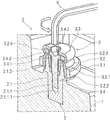
- FIG. 11 is a schematic sectional depiction of an exemplary embodiment according to the invention of an electrical contact unit formed from the on-board electrical system side contact surface and the battery side contact surface,
- FIG. 12 is a schematic perspective depiction of the on-board electrical system side contact surface and the battery side contact surface in an assembly step for producing a screw connection
- FIG. 13 is a schematic perspective depiction of the on-board electrical side contact surface and the battery side contact surface in a disassembly step for releasing the screw connection, and
- FIG. 14 is a schematic perspective depiction of the on-board electrical system side contact surface and the battery side contact surface after the assembly step according to FIG. 13 .
- FIGS. 1 and 2 each schematically show a pole cap 2 . 1 connected to a battery pole 1 , the pole cap 2 . 1 providing a battery side contact surface 2 for producing an electrical connection between the battery pole 1 and an on-board electrical system of a vehicle which is not depicted in more detail.
- FIG. 1 thus shows the pole cap 2 . 1 in a perspective depiction and FIG. 2 in a schematic depiction, in particular in a longitudinal section.
- the battery pole 1 is, for example, an electrical pole of a starter battery of a vehicle, the starter battery not being depicted in more detail and supplying electricity to an output unit and to further vehicle components integrated into the on-board electrical system.
- the pole cap 2 . 1 is electrically conductively connected to the battery pole 1 and is expediently formed from an electrically conductive material, e.g., metal.
- the pole cap 2 . 1 has a fastening portion 2 . 1 . 1 facing towards the battery pole 1 and a sleeve-like contacting portion 2 . 1 . 2 facing away from the battery pole 1 .
- the fastening portion 2 . 1 . 1 is provided with a pole cap side recess 2 . 1 . 1 . 1 extending in the axial direction, into which, for example, a thread which is not depicted in more detail, e.g., an internal thread, is introduced, or which provides a non-profiled surface for producing a profile connection to a self-tapping thread.
- An end of the pole cap side recess 2 . 1 . 1 . 1 is formed herein to taper.
- the sleeve-like contacting portion 2 . 1 . 2 is—seen from above—formed by an outer periphery widening conically in the direction of the battery pole 1 and an inner periphery tapering conically in the direction of the battery pole 1 , whereby the battery side contact surface 2 is enlarged in comparison to the prior art and higher currents can be transmitted.
- a through opening formed by the sleeve-like shaping of the contacting portion 2 . 1 . 2 is enlarged in diameter in comparison to the pole cap side recess 2 . 1 . 1 . 1 , such that a pole cap side stop 2 . 1 . 3 is formed in the transition region between the fastening portion 2 . 1 . 1 and the sleeve-like portion 2 . 1 . 2 , the stop extending in the peripheral direction and forming an annular stop surface according to the exemplary embodiment shown, which will be discussed in more detail later.
- FIGS. 3 to 8 components of an on-board electrical system side contact surface are depicted, which are described individually below. Subsequently, the on-board electrical system side contact surface which is achieved by a terminal 3 shown in FIGS. 9 and 10 is described in more detail in connection with the components described earlier.
- FIG. 3 shows a contact clip 3 . 1 in a perspective depiction.
- the annular contact clip 3 . 1 has a recess 3 . 1 . 1 .
- the contact clip 3 . 1 is electrically conductively connected to at least one connection element of the on-board electrical system, the connection element not being depicted here, for producing an electrical connection between the battery pole 1 and the on-board electrical system.
- the contact clip 3 . 1 is here formed from an electrically conductive material, e.g., metal.
- FIGS. 4 and 5 each depict a terminal sleeve 3 . 2 , wherein the terminal sleeve 3 . 2 is shown in a perspective depiction in FIG. 4 and in a sectional depiction in FIG. 5 , in particular in a longitudinal section.
- the terminal sleeve 3 . 2 is formed double-walled having an inner wall 3 . 2 . 1 and an outer wall 3 . 2 . 2 which open into an annular collar 3 . 2 . 4 on their upper end.
- a gap for positively receiving the sleeve-like contacting portion 2 . 1 . 2 of the pole cap 2 . 1 is formed between the walls.
- the terminal sleeve 3 . 2 . 4 is presently formed as one-piece.
- the outer periphery of the outer wall 3 . 2 . 2 has a portion widening conically or in a tapering manner and an adjoining consistently or cylindrically extending portion, the latter facing towards the pole cap 2 . 1 .
- the inner periphery of the outer wall 3 . 2 . 2 is formed correspondingly to the outer circumference of the sleeve-like contacting portion 2 . 1 . 2 or formed to fit it exactly and thus runs in the direction of the pole cap 2 . 1 in a conically widening manner.
- the radius which is remote from the center of the rotationally symmetrical terminal sleeve 3 . 2 is referred to below as the “outer periphery” and the radius located closer to the center is referred to as the “inner periphery”.
- An outer periphery of the inner wall 3 . 2 . 1 is formed correspondingly to the inner periphery of the pole cap 2 . 1 or formed to fit it exactly and runs—seen in the direction of the pole cap 2 . 1 —in a conically tapering manner.
- the inner periphery of the inner wall 3 . 2 . 1 is presently cylindrical.
- a stop 3 . 2 . 3 is formed inside the annular collar 3 . 2 . 4 at the transition to the inner wall 3 . 2 . 1 on the terminal sleeve side, the stop forming an annular stop surface for a screw connection or similar according to the exemplary embodiment shown.
- a collar 3 . 2 . 4 for producing a crimped connection to a cover element 3 . 3 shown in FIGS. 6 and 7 is formed on an end of the terminal sleeve 3 . 2 , the end facing away from the pole cap 2 . 1 .
- FIGS. 6 and 7 show the cover element 3 . 3 , which is formed as a crimped cover for producing the aforementioned crimped connection and which has a cover side recess 3 . 3 . 1 for receiving a fastening screw 3 . 4 shown in FIG. 8 .
- FIG. 8 shows the fastening screw 3 . 4 in a perspective depiction.
- the fastening screw 3 . 4 is provided with the external thread 3 . 4 . 1 , which, in the assembled state of the electrical contact unit E, is in operative engagement with the thread in the pole cap side recess 2 . 1 . 1 . 1 .
- a flange 3 . 4 . 1 enlarging a diameter of the fastening screw 3 . 4 is formed—again seen in relation to the fastening on the pole cap—on an end region of the fastening screw 3 . 4 , the end region facing away from the pole cap 2 . 1 .
- the fastening screw 3 . 4 according to the exemplary embodiment shown is formed with an internal hexagon socket drive profile 3 . 4 . 3 for a simple assembly and disassembly of the electrical contact unit E, as described in more detail later.
- the components described above form the on-board electrical system side terminal 3 in the assembled state, as exemplified in FIGS. 9 and 10 .
- the on-board electrical system side terminal 3 is depicted in the assembled state in FIG. 9 in a perspective depiction and in a sectional depiction in FIG. 10 , in particular in a longitudinal section.
- the annular contact clip 3 . 1 with its recess 3 . 1 . 1 engages the uniformly or cylindrically running portion of the outer periphery of the outer wall 3 . 2 . 2 of the terminal sleeve 3 . 2 , such that these are positively and electrically conductively connected to each other, wherein the annular recess 3 . 1 . 1 of the contact clip 3 . 1 is narrowed—for example by means of a screw which is not shown—and clamps the terminal sleeve 3 . 2 , such that a frictional connection forms between the contact clip 3 . 1 and the terminal sleeve 3 . 2 .
- the contact between terminal sleeve 3 . 2 and contact clip 3 . 1 can also be produced by compressing, welding or soldering.
- the fastening screw 3 . 4 is arranged through the cover side recess 3 . 3 . 1 and through the terminal sleeve 3 . 2 , wherein a region of the fastening screw 3 . 4 , the region comprising the external thread 3 . 4 . 1 , protrudes portionally out of the terminal sleeve 3 . 2 and an end of the fastening screw 3 . 4 comprising the hexagon socket drive profile 3 . 4 . 3 is flush with the cover element 3 . 3 .
- the flange 3 . 4 . 2 of the fastening screw 3 . 4 rests on the terminal sleeve side stop 3 . 2 . 3 .
- the cover element 3 . 3 is frictionally connected to the cover element 3 . 2 for fixing the fastening screw 3 . 4 within the on-board electrical system side terminal 3 by a crimpled edge of the cover element 3 . 3 enclosing the collar 3 . 2 . 4 being arranged on the terminal sleeve 3 . 2 .
- the fastening screw 3 . 4 cannot be moved through the cover side recess 3 . 3 . 1 due to the flange 3 . 4 . 2 having an enlarged diameter, such that the fastening screw 3 .
- the on-board electrical system side terminal 3 is fixed in the on-board electrical system side terminal 3 in a captive manner yet is rotatable with respect to terminal sleeve and cover element. Since the cover element 3 . 3 is additionally frictionally connected to the terminal sleeve 3 . 2 and this terminal sleeve 3 . 2 is in turn frictionally connected to the contact clip 3 . 1 , the on-board electrical system side terminal 3 can be connected as a structural unit to the battery side contact surface 2 .
- FIG. 11 shows an electrical contact unit E which is formed by connection of the on-board electrical system side contact surface to the battery side contact surface 2 .
- the on-board electrical system side terminal 3 is frictionally connected to the battery side sleeve-like contacting portion 2 . 1 . 2 by screwing.
- a portion of the external thread 3 . 4 . 1 of the fastening screw 3 . 4 engages with the thread of the pole cap side recess 2 . 1 . 1 . 1 .
- the sleeve-like contacting portion 2 . 1 . 2 of the pole cap 2 . 1 is positively received by the gap between the inner wall 3 . 2 . 1 and the outer wall 3 . 2 . 2 .
- the inner wall 3 . 2 . 1 can be pressed radially outwards as a result of the inner periphery of the inner wall 3 . 2 . 1 running in a conically tapering manner in the direction of the pole cap 2 . 1 , by means of which a clamping connection is additionally produced between the pole cap 2 . 1 and the terminal sleeve 3 . 2 .
- FIG. 12 shows an assembly step before the assembling of the electrical contact unit E, wherein a direction for the on-board electrical system side terminal 3 is predetermined by means of an axial arrow, in which direction the terminal 3 is moved towards the pole cap 2 and is arranged on this for assembly.
- a further axial arrow gives a movement direction of a hex wrench 4 for introduction into the hexagonal socket drive profile 3 . 4 . 3 of the fastening screw 3 . 4 .
- a curved arrow gives a direction of rotation, here clockwise, for the hex wrench 4 , for producing the screw connection between the on-board electrical system side contact surface in the form of the terminal 3 and the battery side contact surface 2 in the form of the sleeve-like contacting surface 2 . 1 . 2 .
- FIG. 13 shows a disassembly step for releasing the screw connection between the on-board electrical system side terminal 3 and the battery side contacting portion 2 . 1 . 2 , wherein a direction of rotation of the hex wrench 4 is provided counter-clockwise.
- FIG. 14 shows the on-board electrical system side terminal 3 and the battery side contacting portion 2 . 1 . 2 after the disassembly step shown in FIG. 13 , wherein the terminal 3 is released from the battery side contact surface 2 as a structural unit.
Landscapes
- Chemical & Material Sciences (AREA)
- Chemical Kinetics & Catalysis (AREA)
- Electrochemistry (AREA)
- General Chemical & Material Sciences (AREA)
- Engineering & Computer Science (AREA)
- Manufacturing & Machinery (AREA)
- Connection Of Batteries Or Terminals (AREA)
- Battery Mounting, Suspending (AREA)
- Insulating Bodies (AREA)
- Cable Accessories (AREA)
Abstract
Description
Claims (8)
Applications Claiming Priority (3)
| Application Number | Priority Date | Filing Date | Title |
|---|---|---|---|
| DE102015013472.8 | 2015-10-17 | ||
| DE102015013472.8A DE102015013472A1 (en) | 2015-10-17 | 2015-10-17 | Electrical contact unit for producing an electrical connection between a battery terminal and a vehicle electrical system of a vehicle |
| PCT/EP2016/001705 WO2017063745A1 (en) | 2015-10-17 | 2016-10-14 | Battery pole and electrical contact unit for establishing an electrical connection between a battery pole and an on-board electrical system of a vehicle |
Publications (2)
| Publication Number | Publication Date |
|---|---|
| US20180309111A1 US20180309111A1 (en) | 2018-10-25 |
| US10950844B2 true US10950844B2 (en) | 2021-03-16 |
Family
ID=55698596
Family Applications (1)
| Application Number | Title | Priority Date | Filing Date |
|---|---|---|---|
| US15/768,465 Expired - Fee Related US10950844B2 (en) | 2015-10-17 | 2016-10-14 | Battery pole and electrical contact unit for producing an electrical connection between a battery pole and an on-board electrical system of a vehicle |
Country Status (10)
| Country | Link |
|---|---|
| US (1) | US10950844B2 (en) |
| EP (1) | EP3363064B1 (en) |
| JP (1) | JP6559342B2 (en) |
| KR (1) | KR102045164B1 (en) |
| CN (1) | CN108140798B (en) |
| DE (1) | DE102015013472A1 (en) |
| ES (1) | ES2834014T3 (en) |
| PL (1) | PL3363064T3 (en) |
| WO (1) | WO2017063745A1 (en) |
| ZA (1) | ZA201802307B (en) |
Families Citing this family (7)
| Publication number | Priority date | Publication date | Assignee | Title |
|---|---|---|---|---|
| DE102017210406A1 (en) * | 2017-06-21 | 2018-12-27 | Bayerische Motoren Werke Aktiengesellschaft | Power distributor of a vehicle |
| DE102018127837B3 (en) | 2018-11-07 | 2020-04-23 | Eugen Forschner Gmbh | System comprising at least one battery and a device for energy distribution and / or energy conversion |
| US11239534B2 (en) * | 2018-12-11 | 2022-02-01 | GM Global Technology Operations LLC | Compression clamp battery connection system |
| KR102465877B1 (en) * | 2020-09-23 | 2022-11-11 | 주식회사 비파워 | High voltage current power acquisition device |
| CN112713358A (en) * | 2020-12-11 | 2021-04-27 | 安徽力普拉斯电源技术有限公司 | Spliced storage battery |
| DE102021100851A1 (en) | 2021-01-18 | 2022-07-21 | Lisa Dräxlmaier GmbH | contact system |
| US11749931B2 (en) * | 2021-12-21 | 2023-09-05 | GM Global Technology Operations LLC | Electrical connection unit for high-voltage battery packs |
Citations (7)
| Publication number | Priority date | Publication date | Assignee | Title |
|---|---|---|---|---|
| JP2003092101A (en) | 2001-09-18 | 2003-03-28 | Fujikura Ltd | Battery terminal |
| DE10221057A1 (en) | 2002-05-10 | 2003-11-27 | Wilfried Plaetzer | Connector for use with vehicle electrical batteries is of metal and fits on battery terminal post and is secured using a clamping nut that screws onto a threaded section |
| US20100116455A1 (en) * | 2004-01-02 | 2010-05-13 | Water Gremlin Company | Battery parts and associated systems and methods |
| DE202010016520U1 (en) | 2009-12-11 | 2011-03-03 | Intercable Gmbh | Battery terminal with inner clamp and outer clamp |
| EP2333905A1 (en) | 2009-12-11 | 2011-06-15 | Intercable GmbH | Battery clamp with internal clamp and external clamp |
| DE102013005962A1 (en) | 2013-04-09 | 2014-10-09 | Franz Josef Marx | Battery terminal |
| WO2015054840A1 (en) | 2013-10-16 | 2015-04-23 | 台湾立凯绿能移动股份有限公司 | Method for confirming locked state of battery contact dedicated to electric vehicle |
Family Cites Families (4)
| Publication number | Priority date | Publication date | Assignee | Title |
|---|---|---|---|---|
| US4560230A (en) * | 1984-04-16 | 1985-12-24 | Inglis Douglas R | Battery jump cable system |
| JPH0917414A (en) * | 1995-06-26 | 1997-01-17 | Yazaki Corp | Battery terminal |
| KR970047273U (en) * | 1995-12-29 | 1997-07-31 | Battery terminal fastening device of vehicle | |
| ITMI20062466A1 (en) * | 2006-12-21 | 2008-06-22 | Eni Spa | MODULAR REACTOR FOR EXOTERMIC-ENDOTHERMAL CHEMICAL REACTIONS |
-
2015
- 2015-10-17 DE DE102015013472.8A patent/DE102015013472A1/en not_active Withdrawn
-
2016
- 2016-10-14 US US15/768,465 patent/US10950844B2/en not_active Expired - Fee Related
- 2016-10-14 EP EP16790876.3A patent/EP3363064B1/en active Active
- 2016-10-14 WO PCT/EP2016/001705 patent/WO2017063745A1/en not_active Ceased
- 2016-10-14 CN CN201680060405.1A patent/CN108140798B/en not_active Expired - Fee Related
- 2016-10-14 JP JP2018518994A patent/JP6559342B2/en not_active Expired - Fee Related
- 2016-10-14 PL PL16790876.3T patent/PL3363064T3/en unknown
- 2016-10-14 KR KR1020187010289A patent/KR102045164B1/en not_active Expired - Fee Related
- 2016-10-14 ES ES16790876T patent/ES2834014T3/en active Active
-
2018
- 2018-04-09 ZA ZA2018/02307A patent/ZA201802307B/en unknown
Patent Citations (8)
| Publication number | Priority date | Publication date | Assignee | Title |
|---|---|---|---|---|
| JP2003092101A (en) | 2001-09-18 | 2003-03-28 | Fujikura Ltd | Battery terminal |
| DE10221057A1 (en) | 2002-05-10 | 2003-11-27 | Wilfried Plaetzer | Connector for use with vehicle electrical batteries is of metal and fits on battery terminal post and is secured using a clamping nut that screws onto a threaded section |
| US20100116455A1 (en) * | 2004-01-02 | 2010-05-13 | Water Gremlin Company | Battery parts and associated systems and methods |
| DE202010016520U1 (en) | 2009-12-11 | 2011-03-03 | Intercable Gmbh | Battery terminal with inner clamp and outer clamp |
| EP2333905A1 (en) | 2009-12-11 | 2011-06-15 | Intercable GmbH | Battery clamp with internal clamp and external clamp |
| DE102013005962A1 (en) | 2013-04-09 | 2014-10-09 | Franz Josef Marx | Battery terminal |
| WO2015054840A1 (en) | 2013-10-16 | 2015-04-23 | 台湾立凯绿能移动股份有限公司 | Method for confirming locked state of battery contact dedicated to electric vehicle |
| US9559464B2 (en) | 2013-10-16 | 2017-01-31 | Aleees Eco Ark (Cayman) Co. Ltd. | Positive locking confirmation mechanism for battery contact of electric vehicle |
Non-Patent Citations (3)
| Title |
|---|
| Chinese Office Action issued in Chinese application No. 201680060405.1 dated Apr. 2, 2020, with partial English translation (Nine (9) pages). |
| Korean Office Action issued in Korean counterpart application No. 10-2018-7010289 dated Mar. 5, 2019 (Seven (7) pages). |
| PCT/EP2016/001705, International Search Report dated Feb. 21, 2017 (Two (2) pages). |
Also Published As
| Publication number | Publication date |
|---|---|
| EP3363064A1 (en) | 2018-08-22 |
| KR20180051623A (en) | 2018-05-16 |
| JP6559342B2 (en) | 2019-08-14 |
| CN108140798A (en) | 2018-06-08 |
| DE102015013472A1 (en) | 2016-04-28 |
| EP3363064B1 (en) | 2020-08-19 |
| US20180309111A1 (en) | 2018-10-25 |
| CN108140798B (en) | 2020-11-27 |
| KR102045164B1 (en) | 2019-11-14 |
| ZA201802307B (en) | 2019-01-30 |
| PL3363064T3 (en) | 2021-03-22 |
| WO2017063745A8 (en) | 2018-05-03 |
| JP2018534739A (en) | 2018-11-22 |
| ES2834014T3 (en) | 2021-06-16 |
| BR112018007301A2 (en) | 2018-10-23 |
| BR112018007301A8 (en) | 2022-12-27 |
| WO2017063745A1 (en) | 2017-04-20 |
Similar Documents
| Publication | Publication Date | Title |
|---|---|---|
| US10950844B2 (en) | Battery pole and electrical contact unit for producing an electrical connection between a battery pole and an on-board electrical system of a vehicle | |
| US7357671B2 (en) | Coaxial plug-type connector and method for mounting the same | |
| JP6219917B2 (en) | Electrical connection tightened against rotation for electrically heatable honeycomb bodies | |
| US10128615B2 (en) | Variable-clocking terminal assembly | |
| US8414321B2 (en) | Power element for a motor of an industrial truck | |
| JP2003331943A (en) | Contact element with connection for litz conductor | |
| US9660363B2 (en) | Battery terminal | |
| US6071155A (en) | Electrical wire mounting structure | |
| US20120153611A1 (en) | Coupling arrangement comprising a coupling body and a metal pipe, as well as method for assembly of the coupling body | |
| US8579653B2 (en) | Electrical plug connector having a contact element with inwardly and outwardly protruding knobs | |
| US5823829A (en) | Connection body's fitting connection structures and sockets structures to hold an electric bulb | |
| RU2016128555A (en) | HIGH VOLTAGE CABLE FORK | |
| JP2012077910A (en) | Device for tension-discharging fixing of cable | |
| JP2003074850A (en) | Water preheating connecting piece | |
| RU2008113197A (en) | INSERT FOR PLACEMENT IN THE ELEMENT FOR FIXING AND SECURING THE ELECTRICAL CONTACT OF THE CABLE CONNECTING TERMINAL | |
| CN113169465B (en) | electrical connector | |
| JP6771510B2 (en) | Electrical contact assembly | |
| CN107534233B (en) | Battery terminal and method for producing a battery terminal | |
| US20200185692A1 (en) | Compression clamp battery connection system | |
| KR20200001429U (en) | Connecting structure for coaxial cable | |
| CN206194983U (en) | Electrical contact elements for clamping connection of stranded conductors | |
| JP4968529B2 (en) | connector | |
| JP2007128801A (en) | Terminal structure | |
| EP0637100A1 (en) | Fitting/connection structure of connection member and holding structure of lamp to socket | |
| RU2358363C1 (en) | Electrical connector |
Legal Events
| Date | Code | Title | Description |
|---|---|---|---|
| FEPP | Fee payment procedure |
Free format text: ENTITY STATUS SET TO UNDISCOUNTED (ORIGINAL EVENT CODE: BIG.); ENTITY STATUS OF PATENT OWNER: LARGE ENTITY |
|
| AS | Assignment |
Owner name: DAIMLER AG, GERMANY Free format text: ASSIGNMENT OF ASSIGNORS INTEREST;ASSIGNOR:SCHUMACHER, ERIC;REEL/FRAME:045736/0364 Effective date: 20180416 |
|
| STPP | Information on status: patent application and granting procedure in general |
Free format text: DOCKETED NEW CASE - READY FOR EXAMINATION |
|
| STPP | Information on status: patent application and granting procedure in general |
Free format text: NON FINAL ACTION MAILED |
|
| STPP | Information on status: patent application and granting procedure in general |
Free format text: RESPONSE TO NON-FINAL OFFICE ACTION ENTERED AND FORWARDED TO EXAMINER |
|
| STPP | Information on status: patent application and granting procedure in general |
Free format text: NON FINAL ACTION MAILED |
|
| STPP | Information on status: patent application and granting procedure in general |
Free format text: FINAL REJECTION MAILED |
|
| STPP | Information on status: patent application and granting procedure in general |
Free format text: NOTICE OF ALLOWANCE MAILED -- APPLICATION RECEIVED IN OFFICE OF PUBLICATIONS |
|
| STCF | Information on status: patent grant |
Free format text: PATENTED CASE |
|
| AS | Assignment |
Owner name: DAIMLER TRUCK AG, GERMANY Free format text: ASSIGNMENT OF ASSIGNORS INTEREST;ASSIGNOR:DAIMLER AG;REEL/FRAME:061629/0616 Effective date: 20220524 |
|
| FEPP | Fee payment procedure |
Free format text: MAINTENANCE FEE REMINDER MAILED (ORIGINAL EVENT CODE: REM.); ENTITY STATUS OF PATENT OWNER: LARGE ENTITY |
|
| LAPS | Lapse for failure to pay maintenance fees |
Free format text: PATENT EXPIRED FOR FAILURE TO PAY MAINTENANCE FEES (ORIGINAL EVENT CODE: EXP.); ENTITY STATUS OF PATENT OWNER: LARGE ENTITY |
|
| STCH | Information on status: patent discontinuation |
Free format text: PATENT EXPIRED DUE TO NONPAYMENT OF MAINTENANCE FEES UNDER 37 CFR 1.362 |
|
| FP | Lapsed due to failure to pay maintenance fee |
Effective date: 20250316 |