US10948430B2 - Method and device for determining CT system parameter - Google Patents
Method and device for determining CT system parameter Download PDFInfo
- Publication number
- US10948430B2 US10948430B2 US16/627,255 US201716627255A US10948430B2 US 10948430 B2 US10948430 B2 US 10948430B2 US 201716627255 A US201716627255 A US 201716627255A US 10948430 B2 US10948430 B2 US 10948430B2
- Authority
- US
- United States
- Prior art keywords
- mould body
- ray
- projection
- detection surface
- plane
- Prior art date
- Legal status (The legal status is an assumption and is not a legal conclusion. Google has not performed a legal analysis and makes no representation as to the accuracy of the status listed.)
- Active
Links
- 238000000034 method Methods 0.000 title claims abstract description 45
- 238000001514 detection method Methods 0.000 claims abstract description 84
- 238000002591 computed tomography Methods 0.000 claims description 87
- 230000008569 process Effects 0.000 claims description 11
- 238000003860 storage Methods 0.000 claims description 10
- 230000000737 periodic effect Effects 0.000 claims description 9
- 238000004590 computer program Methods 0.000 claims description 6
- 238000004891 communication Methods 0.000 claims description 5
- 238000012216 screening Methods 0.000 claims 1
- 238000010586 diagram Methods 0.000 description 6
- 238000004519 manufacturing process Methods 0.000 description 6
- 229910000831 Steel Inorganic materials 0.000 description 3
- 239000010959 steel Substances 0.000 description 3
- 230000006870 function Effects 0.000 description 2
- 238000003384 imaging method Methods 0.000 description 2
- 230000009286 beneficial effect Effects 0.000 description 1
- 230000008859 change Effects 0.000 description 1
- 238000013500 data storage Methods 0.000 description 1
- 230000001066 destructive effect Effects 0.000 description 1
- 238000005516 engineering process Methods 0.000 description 1
- 230000010354 integration Effects 0.000 description 1
- 238000003754 machining Methods 0.000 description 1
- 235000013372 meat Nutrition 0.000 description 1
- 230000004048 modification Effects 0.000 description 1
- 238000012986 modification Methods 0.000 description 1
- 230000003287 optical effect Effects 0.000 description 1
- 239000013307 optical fiber Substances 0.000 description 1
- 230000001681 protective effect Effects 0.000 description 1
- 239000004065 semiconductor Substances 0.000 description 1
- 238000006467 substitution reaction Methods 0.000 description 1
Images


Classifications
-
- G—PHYSICS
- G01—MEASURING; TESTING
- G01N—INVESTIGATING OR ANALYSING MATERIALS BY DETERMINING THEIR CHEMICAL OR PHYSICAL PROPERTIES
- G01N23/00—Investigating or analysing materials by the use of wave or particle radiation, e.g. X-rays or neutrons, not covered by groups G01N3/00 – G01N17/00, G01N21/00 or G01N22/00
- G01N23/02—Investigating or analysing materials by the use of wave or particle radiation, e.g. X-rays or neutrons, not covered by groups G01N3/00 – G01N17/00, G01N21/00 or G01N22/00 by transmitting the radiation through the material
- G01N23/04—Investigating or analysing materials by the use of wave or particle radiation, e.g. X-rays or neutrons, not covered by groups G01N3/00 – G01N17/00, G01N21/00 or G01N22/00 by transmitting the radiation through the material and forming images of the material
- G01N23/046—Investigating or analysing materials by the use of wave or particle radiation, e.g. X-rays or neutrons, not covered by groups G01N3/00 – G01N17/00, G01N21/00 or G01N22/00 by transmitting the radiation through the material and forming images of the material using tomography, e.g. computed tomography [CT]
-
- A—HUMAN NECESSITIES
- A61—MEDICAL OR VETERINARY SCIENCE; HYGIENE
- A61B—DIAGNOSIS; SURGERY; IDENTIFICATION
- A61B6/00—Apparatus for radiation diagnosis, e.g. combined with radiation therapy equipment
- A61B6/02—Devices for diagnosis sequentially in different planes; Stereoscopic radiation diagnosis
- A61B6/03—Computerised tomographs
-
- G—PHYSICS
- G01—MEASURING; TESTING
- G01B—MEASURING LENGTH, THICKNESS OR SIMILAR LINEAR DIMENSIONS; MEASURING ANGLES; MEASURING AREAS; MEASURING IRREGULARITIES OF SURFACES OR CONTOURS
- G01B11/00—Measuring arrangements characterised by the use of optical techniques
- G01B11/02—Measuring arrangements characterised by the use of optical techniques for measuring length, width or thickness
- G01B11/03—Measuring arrangements characterised by the use of optical techniques for measuring length, width or thickness by measuring coordinates of points
-
- G—PHYSICS
- G01—MEASURING; TESTING
- G01N—INVESTIGATING OR ANALYSING MATERIALS BY DETERMINING THEIR CHEMICAL OR PHYSICAL PROPERTIES
- G01N2223/00—Investigating materials by wave or particle radiation
- G01N2223/30—Accessories, mechanical or electrical features
- G01N2223/303—Accessories, mechanical or electrical features calibrating, standardising
-
- G—PHYSICS
- G01—MEASURING; TESTING
- G01N—INVESTIGATING OR ANALYSING MATERIALS BY DETERMINING THEIR CHEMICAL OR PHYSICAL PROPERTIES
- G01N2223/00—Investigating materials by wave or particle radiation
- G01N2223/30—Accessories, mechanical or electrical features
- G01N2223/306—Accessories, mechanical or electrical features computer control
Definitions
- the present disclosure relates to the field of computer imaging technology, and more particularly to method and device for determining CT system parameter.
- a computed tomography (CT) system is a computer imaging system capable of acquiring images of the interior of an object in a non-destructive manner.
- the CT system includes: an X-ray (also known as Roentgen ray) source and a detector.
- the CT system needs to use a CT system parameter (such as coordinates of a foot of a perpendicular of a focus of the X-ray source on a detection surface of the detector) in the process of acquiring images. Therefore, the CT system parameter needs to be determined before using the CT system to acquire the images.
- a fine-structure customized mould body is required.
- the mould body is a structural part embedded with a plurality of small steel balls.
- the customized mould body may be placed between the X-ray source and the detection surface of the detector, and the X-ray source is controlled to emit X-rays to the detection surface.
- X-ray projections of the plurality of small steel balls on the detection surface are acquired. Further, the acquired X-ray projections are analyzed to determine the coordinates of the foot of the perpendicular of the focus of the X-ray source on the detection surface of the detector in geometric parameters of the CT system.
- the customized mould body is required to determine the CT system parameter.
- a manufacturing process of the mould body is relatively complicated because of a higher machining accuracy requirement on the structure of the customized mould body.
- the present disclosure provides a method and a device for determining a CT system parameter.
- the technical solutions are as follows.
- a CT system includes: an X-ray source and a detector.
- the method includes: controlling a mould body to move between the X-ray source and a detection surface of the detector, and acquiring X-ray projections of the mould body during movement on the detection surface, wherein the mould body has a first plane and a second plane perpendicular to each other and the first plane and the second plane are always perpendicular to the detection surface during the movement of the mould body; determining a first straight line and a second straight line according to the acquired X-ray projections, wherein the first straight line is a straight line of a projection line segment of an edge of the first plane in boundary line segments of the acquired X-ray projections, the second straight line is a straight line of a projection line segment of an edge of the second plane in the boundary line segments of the acquired X-ray projections, a plane determined by the first straight line and a focus of the X
- a device for determining a CT system parameter including at least one processor, at least one interface, a memory and at least one communication bus, wherein the processor is configured to execute a program stored in the memory to implement the method for determining CT system parameter in the first aspect.
- a computer-readable storage medium Instructions are stored in the computer-readable storage medium.
- the computer-readable storage medium runs on a computer, the computer is caused to execute the method for determining a CT system parameter in the first aspect.
- a computer program product including instructions.
- the computer program product runs on a computer, the computer is made to execute the method for determining a CT system parameter in the first aspect.
- the technical solutions provided by the present disclosure have the following beneficial effects.
- the CT system parameter can be determined as long as the used mould body has the first plane and the second plane. Moreover, since the structure of the plane is relatively simple, a manufacturing process of the mould body is relatively simple.
- the mould body used in the present disclosure may be a scanning table or a light-limiting door in the CT system. That is, an intrinsic component in the CT system is directly used as the mould body in the present disclosure and thus there is no need to use a customized module body in the process of determining the CT system parameter.
- FIG. 1 is a schematic view showing a structure of a CT system provided by an embodiment of the present disclosure
- FIG. 2 is a schematic view showing a structure of a device for determining a CT system parameter provided by an embodiment of the present disclosure
- FIG. 3 is a flow chart of a method for determining a CT system parameter provided by an embodiment of the present disclosure
- FIG. 4 is a schematic view showing a structure of a scanning table provided by an embodiment of the present disclosure.
- FIG. 5 is a schematic view showing a structure of a light-limiting door provided by an embodiment of the present disclosure
- FIG. 6 is a flow chart of a method for acquiring X-ray projections provided by an embodiment of the present disclosure
- FIG. 7 is a schematic view showing a direction and position of the CT system provided by an embodiment of the present disclosure.
- FIG. 8 is a schematic diagram of a third X-ray projection provided by an embodiment of the present disclosure.
- FIG. 9 is a schematic diagram of a fourth X-ray projection provided by an embodiment of the present disclosure.
- FIG. 10 is a flow chart of a method for determining a first straight line and a second straight line provided by an embodiment of the present disclosure
- FIG. 11 is a schematic diagram of a target X-ray projection provided by an embodiment of the present disclosure.
- FIG. 12 is a schematic diagram of an in-plane rotation angle provided by an embodiment of the present disclosure.
- FIG. 13 is a schematic view showing a direction and position of another CT system provided by an embodiment of the present disclosure.
- FIG. 1 is a schematic view showing a structure of a CT system provided by an embodiment of the present disclosure.
- the CT system 0 may include: an X-ray source 01 , a detector 02 , a scanning table 03 , a light-limiting door (not shown in FIG. 1 ) of the X-ray source 01 , a roller 04 , and a control component (not shown in FIG. 1 ).
- the CT system may also be referred to as a cone-beam CT system, and a CT system parameter may also be referred to as a geometric parameter of the CT system.
- both the X-ray source 01 and the detector 02 may be fixedly arranged on the roller 04 , and the roller 04 can drive the X-ray source 01 and the detector 02 to rotate.
- the X-ray source 01 may also be referred to as a bulb tube.
- the detector 02 has a detection surface located at a light emission side of the X-ray source 01 .
- the scanning table 03 is arranged between the detection surface and the X-ray source 01 .
- the control component can control the scanning table 03 to move upwards or downwards, leftwards or rightwards, or backwards or forwards.
- the light-limiting door is arranged at a light emission portion of the X-ray source 01 , and can limit light emitted from the X-ray source 01 to a preset range.
- the control component can also control the light-limiting door to move.
- the CT system may further include a device for determining a CT system parameter (not shown in FIG. 1 ) in the following embodiments.
- the device for determining a CT system parameter may be a computer or other components having a processing function.
- FIG. 2 is a schematic view showing a structure of a device for determining a CT system parameter 1 provided by an embodiment of the present disclosure.
- the device for determining a CT system parameter 1 may include: at least one processor 10221 (for example, a central processing unit), at least one interface 10222 , a memory 10223 , and at least one bus 10224 .
- the bus 10224 can be configured to implement connection and communication among the processor, the interface and the memory.
- the memory 10223 and the interface 10222 are respectively connected to the processor 10221 through the bus 10224 .
- the processor 10221 is configured to execute an executable module, such as a computer program, stored in the memory 10223 .
- the memory 10223 may include a high-speed random access memory (RAM), and may also include a non-volatile memory, such as at least one magnet disk memory.
- RAM random access memory
- non-volatile memory such as at least one magnet disk memory.
- the communication connection between the device for determining a CT system parameter 1 and at least one other device is implemented through the at least one interface 10222 (in a wired or wireless manner).
- the memory 10223 stores a program 10225 that can be executed by the processor 10221 .
- FIG. 3 is a flow chart of a method for determining a CT system parameter provided by an embodiment of the present disclosure.
- the method for determining a CT system parameter may be configured to determine the CT system parameter as shown in FIG. 1 , and may be used in the CT system parameter determining device as shown in FIG. 2 .
- the method for determining a CT system parameter may include the following steps.
- a mould body having a first plane and a second plane perpendicular to each other is controlled to move between an X-ray source and a detection surface of a detector, and X-ray projections of the mould body during movement on the detection surface are acquired.
- a mould body is required to be used in determination of the CT system parameter and the mould body is required to have a first plane and a second plane perpendicular to each other. That is, the mould body used in the embodiment of the present disclosure is a three-dimensional geometric structure having the first plane and the second plane.
- FIG. 4 is a schematic view showing a structure of a scanning table 03 provided by an embodiment of the present disclosure.
- the scanning table 03 may include a cubic structure, and has two first planes A 1 and two second planes B 1 , and the first planes A 1 are perpendicular to the second planes B 1 . That is, the scanning table in the CT system meets the requirement for the shape of the mould body in the embodiment of the present disclosure. Thus, the scanning table can be used as the mould body.
- FIG. 5 is a schematic view showing a structure of a light-limiting door provided by an embodiment of the present disclosure. As shown in FIG. 5 , the light-receiving door is of a structure with a rectangular through-hole C formed in the middle thereof.
- the light-limiting door in the CT system also meats the requirement for the shape of the mould body in the embodiment of the present disclosure.
- the light-limiting door can also be used as the mould body.
- the scanning table or the light-limiting door in the CT system is used as the mould body is taken as an example.
- the mould body may also be other geometric structure having the first plane and the second plane, which is not limited in the embodiments of the present disclosure.
- FIG. 6 is a flow chart of a method for acquiring X-ray projections provided by an embodiment of the present disclosure. As shown in FIG. 6 , the step 301 may include the following sub-steps.
- step 3011 the module body is controlled to move multiple times in a first direction, and a plurality of third X-ray projections of the mould body on the detection surface is acquired.
- FIG. 7 is a schematic view showing a direction and position of the CT system provided by an embodiment of the present disclosure. As shown in FIG. 7 , a first direction F 1 may be perpendicular to a first plane (and parallel to a detection surface Y).
- the mould body may be controlled to move multiple times in the first direction F 1 , after each time the mould body moves in the first direction F 1 , the X-ray source is controlled to emit X-rays to the detection surface of the detector to make an exposure to the mould body and acquire the third X-ray projection of the mould body on the detection surface Y.
- the mould body may be moved to a top end (i.e., moved to a maximum value of a top in a range of up and down movement of the mould body) or a bottom end (i.e., moved to a maximum value of a bottom in a range of up and down movement of the mould body). Then, the mould body is moved slowly at a constant speed in the first direction or a direction opposite to the first direction (the distance of each movement may be the same, and may be as small as possible). In this process, the mould body may be continuously exposed.
- a rotation center point O of the CT system may be located between a focus S of the X-ray source and the detection surface Y.
- a line of the rotation center point O and the focus S is perpendicular to the detection surface Y.
- the mould body may be moved to the rotation center point O, and then the mould body is moved multiple times from the rotation center point O in the first direction F 1 .
- a mould body control component can control the mould body to move upwards or downwards, leftwards or rightwards, or backwards or forwards.
- the mould body control component may include: an upper computer and a lower computer in the CT system.
- FIG. 8 is a schematic diagram of a third X-ray projection provided by an embodiment of the present disclosure.
- the scanning table 03 is taken as the mould body and the third X-ray projection of the mould body on the detection surface Y is a rectangle J.
- a boundary line segment of the third X-ray projection (namely, a boundary line segment of the rectangle J) may include: a line segment Q 1 , a line segment Q 2 , a line segment K 1 , and a line segment K 2 .
- the line segment Q 1 and the line segment Q 2 are projection line segments of edges of the two first planes A 1 of the mould body on the detection surface Y, respectively.
- the boundary line segment of the third X-ray projection of the mould body on the detection surface Y needs to include: projection line segments of the edges of the two first planes in the m first planes. After multiple times of movements of the mould body, the projection line segments of the edges of two same first planes in the boundary line segments of each third X-ray projection can be acquired, so that a plurality of sets of parallel projection line segments can be acquired.
- the mould body is controlled to perform at least one periodic movement and acquire a plurality of fourth X-ray projections of the mould body on the detection surface, until in one periodic movement process of the mould body, projection line segments of edges of the same second plane in boundary line segments of all the fourth X-ray projections of the mould body are located on the same straight line.
- a second direction may be perpendicular to the second plane.
- a third direction is perpendicular to both the first direction and the second direction.
- the one periodic movement performed by the mould body may include: controlling the mould body to move in the second direction, and controlling the mould body to move multiple times in the third direction after the mould body is controlled to move in the second direction.
- the fourth X-ray projection is the X-ray projection of the mould body on the detection surface during the movement in the third direction.
- a second direction F 2 is parallel to the detection surface Y
- a third direction F 3 is perpendicular to both the first direction F 1 and the second direction F 2 .
- the mould body can be controlled to perform at least one periodic movement at any one coordinate point. That is, the mould body is controlled to move in the second direction F 2 at least once, and is controlled to move multiple times in the third direction F 3 after each time the mould body is controlled to move in the second direction.
- the mould body is controlled to move in the third direction F 3 , it is required to control the X-ray source to emit X-rays to the detection surface of the detector to expose the mould body once, and acquire a fourth X-ray projection of the mould body on the detection surface.
- the boundary line segment of the fourth X-ray projection of the mould body on the detection surface may not include the projection line segment of the edge of the second plane.
- the mould body in the second direction to make the boundary line segment of the fourth X-ray projection of the mould body on the detection surface include the projection line segment of the edge of the second plane, until in one periodic movement process of the mould body, the projection line segments of edges of the same second plane in the boundary line segments of all the fourth X-ray projections are located on the same straight line.
- FIG. 9 is a schematic diagram of a fourth X-ray projection provided by an embodiment of the present disclosure.
- FIG. 9 uses that the mould body is the scanning table 03 as an example, and the view shown in FIG. 9 is a view directly facing the detection surface.
- the fourth X-ray projection of the mould body on the detection surface Y is a rectangle J′
- a boundary line segment of the fourth X-ray projection i.e., a boundary line segment of the rectangle J′
- the line segment Q 1 ′ and the line segment Q 2 ′ are projection line segments of the edges of the two first planes A 1 of the mould body on the detection surface Y, respectively.
- the line segment K 1 ′ is a projection line segment of an edge of one second plane B 1 of the mould body on the detection surface Y.
- the boundary line segments of the fourth X-ray projections of the mould body on the detection surface include: the projection line segments of the edges of the two first planes on the detection surface, and the projection line segment of the edge of the second plane on the detection surface.
- the mould body may be controlled to stop moving.
- a first straight line and a second straight line are determined according to the acquired X-ray projections.
- step 302 may include the following sub-steps.
- step 3021 a target X-ray projection is screened out from the plurality of acquired third X-ray projections.
- the target X-ray projection is a projection with the minimum distance between the projection line segments of the edges of the two first planes (the first plane Z 1 and the first plane Z 2 ) among the boundary line segments of the plurality of third X-ray projections.
- a reference X-ray projection and the target X-ray projection are two X-ray projections continuously acquired from the plurality of third X-ray projections.
- a distance between the projection line segments of the edges of the two first planes (the first plane Z 1 and the first plane Z 2 ) in the boundary line segments of the target X-ray projection is less than a distance between the projection line segments of the edges of the two first planes (the first plane Z 1 and the first plane Z 2 ) in the boundary line segments of the reference X-ray projection.
- a plurality of third X-ray projections may be acquired, wherein distances H of two projection line segments of the edges of the two first planes are all equal in the boundary line segments of all the third X-ray projections located in a range G 1 ; and the third X-ray projection in the range G 1 is the third X-ray projection in which the distance between the projection line segments of the edges of the two first planes is the shortest in the boundary line segments of all the third X-ray projections.
- the reference X-ray projection is a third X-ray projection adjacent to the range G 1 in the plurality of third X-ray projections. Exemplarily, there are two reference X-ray projections in FIG. 11 .
- the mould body After acquiring the reference X-ray projection located below, the mould body is controlled to move upwards to obtain a third X-ray projection (referred to as the target X-ray projection located below in the embodiment of the present disclosure) in the range G 1 .
- the mould body is controlled to move downwards to obtain a third X-ray projection (referred to as the target X-ray projection located above in the embodiment of the present disclosure) in the range G 1 .
- step 3021 there are two target X-ray projections (the target X-ray projection located above and the target X-ray projection located below) in the range G 1 .
- either of the target X-ray projections may be selected.
- the target X-ray projection located above may be selected as an example from the two target X-ray projections.
- the target X-ray projection located below can also be selected in step 3021 .
- a straight line of a projection line segment away from the center of the reference X-ray projection in the projection line segments of the edges of the two first planes in the boundary line segment of the target X-ray projection is determined as the first straight line.
- the boundary line segment of the target X-ray projection may include projection line segments Q 1 and Q 2 of the edges of the two first planes.
- the projection line segments of the edges of the two first planes there is a projection line segment Q 1 close to a center I of the reference X-ray projection (as the target X-ray projection and the reference X-ray projection are two third X-ray projections continuously acquired, the reference X-ray projection is the reference X-ray projection located above), and there is a projection line segment Q 2 away from the center I of the reference X-ray projection.
- a straight line of the projection line segment Q 2 away from the reference X-ray projection may be determined as the first straight line.
- a plane determined by the first straight line and a focus of the X-ray source is perpendicular to the detection surface.
- step 3023 the same straight line is determined as the second straight line.
- the same straight line is the second straight line.
- a plane determined by the second straight line and the focus of the X-ray source is perpendicular to the detection surface.
- step 303 an intersection point of the first straight line and the second straight line is determined as coordinates of a foot of a perpendicular of the focus of the X-ray source on the detection surface.
- a CT system parameter may include the coordinates of the foot of the perpendicular of the focus of the X-ray source on the detection surface.
- coordinates of the intersection point O′ of the first straight line Lu and the second straight line Lv may be determined as the coordinates of the foot of the perpendicular of the focus S of the X-ray source on the detection surface Y.
- an in-plane rotation angle of the detector is determined according to any one of the line segments in the boundary line segments of any one of the X-ray projections of the mould body.
- a plurality of X-ray projections is acquired in step 301 .
- the in-plane rotation angle of the detector can be determined according to any one of the line segments in the boundary line segments of any one of the X-ray projections acquired in step 301 .
- a two-dimensional coordinate system may be established on the detection surface.
- the origin of the two-dimensional coordinate system may be an apex angle of the detection surface; and two coordinate axes (a coordinate axis 1 and a coordinate axis 2 ) of the two-dimensional coordinate system may be the two edges constituting the apex angle on the detection surface, respectively.
- an angle ⁇ formed by the projection line segment Q 1 and the longer edge of the detection surface (which is rectangular) can be calculated according to the location of Q 1 in the two-dimensional coordinate system and a geometric relationship and a is used as the in-plane rotation angle of the detector.
- an angle ⁇ formed by the projection line segment K 1 ′ and the shorter edge of the detection surface (which is rectangular) can be calculated according to the location of K 1 ′ in the two-dimensional coordinate system and the geometric relationship and ⁇ is used as the in-plane rotation angle of the detector.
- step 305 the mould body is moved to make a mark point on the mould body to coincide with a first coordinate point, and a first X-ray projection of the mould body on the detection surface is acquired.
- the mould body may be provided with the mark point which may be located at any location on the mould body.
- the mark point may be located on one of the first planes on the mould body.
- the first coordinate point may be located on a plane which passes through the rotation center point and parallel to the first plane.
- the first coordinate point may coincide with the rotation center point.
- the mould body may be controlled to move to make the mark point on the mould body to move to the first coordinate point; and the X-ray source is controlled to emit X-rays to the detection surface of the detector to make an exposure of the mould body, so as to acquire the first X-ray projection.
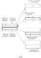
- FIG. 13 is a schematic view showing a direction and position of another CT system provided by an embodiment of the present disclosure. It should be noted that FIG. 13 is a front view of the CT system. As shown in FIG. 13 , when the mark point coincides with the first coordinate point, both the first coordinate point and the mark point may be located at the location of a point P 1 which may be located at the center of one of the first planes of the mould body M. Of course, the P 1 is not necessarily located at the center of one of the first planes of the mould body M, which is not limited in the embodiments of the present disclosure.
- the boundary line segment of the first X-ray projection may at least include the projection line segments of the edges of the two first planes in the mould body M on the detection surface Y, which are a line segment Q 1 and a line segment Q 2 (since FIG. 13 is a side view of the detector, both the line segments Q 1 and Q 2 are represented as points).
- the boundary line segment of the first X-ray projection may at least include a projection line segment (not shown in FIG. 13 ) of an edge of one second plane in the mould body M on the detection surface Y, and the length of the projection line segment is equal to the distance between Q 1 and Q 2 in FIG. 13 .
- step 306 the mark point on the mould body is controlled to move from the first coordinate point to the second coordinate point, and a second X-ray projection on the mould body on the detection surface is acquired.
- the mold body M may be controlled to move from the first coordinate point P 1 to the second coordinate point P 2 ; and the X-ray source is controlled to emit X-rays to the detection surface of the detector to make an exposure of the mould body, so as to acquire the second X-ray projection.
- the mould body is moved by d 1 from the first coordinate point P 1 in the third direction; and then, the mould body M is moved by d 2 in the first direction.
- the mould body may be moved one time or multiple times only in one direction so as to change the location of the mould body, which is not limited in the embodiments of the present disclosure.
- the X-ray projection of the mould body M on the detection surface Y is a second X-ray projection.
- the boundary line segment of the second X-ray projection may at least include projection line segments (a line segment Q 3 and a line segment Q 4 , respectively) of the edges of the two first planes in the mould body M on the detection surface Y.
- the boundary line segment of the second X-ray projection may at least include a projection line segment of an edge of one second plane in the mould body M on the detection surface Y, and the length of the projection line segment is equal to the distance between Q 3 and Q 4 in FIG. 13 .
- a distance between the focus of the X-ray source and the detection surface, as well as a distance between the focus and the rotation center point is determined according to a geometric relationship among the first X-ray projection, the second X-ray projection, the first coordinate point, and the second coordinate point.
- a similar triangle principle in the geometric relationship may be combined (of course, other principles in the geometric relationship may also be combined, which is not limited in the embodiments of the present disclosure) to determine the distance D between the focus S of the X-ray source and the detection surface. For example, if the length of the mould body in the first direction is H and the length of the mould body in the third direction is W, the following three equations can be derived according to the geometric relationship:
- Q 1 Q 2 represents the distance between the line segment Q 1 and the line segment Q 2 ;
- Q 1 Q 4 represents the distance between the line segment Q 1 and the line segment Q 4 ;
- L 1 represents the distance from the focus to a surface near the focus in the mould body.
- Q 2 and Q 3 may be coincided with each other, which is not limited in the embodiments of the present disclosure.
- the following CT system parameters (a total of five parameters) are obtained in a calibrating manner in the embodiment of the present disclosure: the coordinates of the foot of the perpendicular (including two parameters of a horizontal coordinate and a vertical coordinate in the coordinate system of the foot of the perpendicular on the detection surface) of the focus on the detection surface, the in-plane rotation angle of the detection surface, the distance between the focus and the detection surface, and the distance between the focus and the rotation center point.
- the mould body used in steps 301 to 307 may be the scanning table in the CT system, or may be the light-limiting door in the CT system.
- the mould body used in step 301 to step 304 and the mould body used in step 305 to step 307 may be different.
- the mould body used in steps 301 to 304 is the light-limiting door
- the mould body used in steps 305 to 307 is the scanning table, which is not limited in the embodiments of the present disclosure.
- the CT system parameter can be determined as long as the used mould body has the first plane and the second plane. Moreover, since the structure of the plane is relatively simple, a manufacturing process of the mould body is relatively simple.
- the structure of the plane is relatively simple, there is no need to spend more cost in manufacturing the mould body. That is, the cost of manufacturing the mould body used in the embodiments of the present disclosure is lower. Thus, the cost of determining the CT system parameter in the embodiments of the present disclosure is lower.
- the manufactured mould body is apt to have a large error, thereby affecting the accuracy of the determined CT system parameter.
- the structure of the used mould body is relatively simple (only the first plane and the second plane are required), the error of the manufactured mould body is small and thus the accuracy of the determined CT system parameter is improved.
- the mould body used in the embodiment of the present disclosure may be the scanning table or the light-limiting door in the CT system. That is, an intrinsic component in the CT system is directly used as the mould body in the embodiment of the present disclosure and thus there is no need to use a customized module body in the process of determining the CT system parameter.
- the embodiment of the present disclosure can be applicable not only to a CT system in which the X-ray source and the detector are rotatable, but also to a CT system in which the locations of the X-ray source and the detector are unadjustable.
- the above embodiments may be implemented in whole or in part by hardware, software, firmware or any one of combinations thereof.
- the embodiments When implemented by the software, the embodiments may be implemented in whole or in part in the form of a computer program product including one or more computer instructions.
- the computer program instructions When the computer program instructions are loaded and executed on a computer, processes or functions described in the embodiments of the present disclosure are generated in whole or in part.
- the computer may be a general-purpose computer, a computer network, or other programmable devices.
- the computer instructions may be stored in a readable storage medium of the computer or may be transferred from one computer-readable storage medium to another computer-readable storage medium.
- the computer instructions may be transferred from one website site, computer, server or data center to another website site, computer, server, or data center in a wired (e.g., through a coaxial cable, an optical fiber, or a digital subscriber line) or wireless (e.g., through infrared, wireless, or microwave) manner.
- the computer-readable storage medium may be any available medium that can be accessed by the computer or data storage equipment such as the server and data center that includes one or more available medium integration.
- the available medium may be a magnetic medium (e.g., a floppy disk, a hard disk, or a magnetic tape), an optical medium, a semiconductor medium (e.g., a solid-state hard disk), or the like.
- the embodiments for the method for determining the CT system parameter and the embodiments for the device for determining the CT system parameter can refer to each other, which is not limited in the present disclosure.
- first and second are used for descriptive purposes only and should not be construed to indicate or imply the relative importance.
- the term “a plurality of” refers to two or more, unless explicitly defined otherwise.
Abstract
Description
Claims (19)
Applications Claiming Priority (1)
| Application Number | Priority Date | Filing Date | Title |
|---|---|---|---|
| PCT/CN2017/090378 WO2019000234A1 (en) | 2017-06-27 | 2017-06-27 | Ct system parameter determining method and device |
Publications (2)
| Publication Number | Publication Date |
|---|---|
| US20200132612A1 US20200132612A1 (en) | 2020-04-30 |
| US10948430B2 true US10948430B2 (en) | 2021-03-16 |
Family
ID=64741046
Family Applications (1)
| Application Number | Title | Priority Date | Filing Date |
|---|---|---|---|
| US16/627,255 Active US10948430B2 (en) | 2017-06-27 | 2017-06-27 | Method and device for determining CT system parameter |
Country Status (3)
| Country | Link |
|---|---|
| US (1) | US10948430B2 (en) |
| CN (1) | CN110461236B (en) |
| WO (1) | WO2019000234A1 (en) |
Families Citing this family (1)
| Publication number | Priority date | Publication date | Assignee | Title |
|---|---|---|---|---|
| CN113892959B (en) * | 2021-09-26 | 2024-03-26 | 有方(合肥)医疗科技有限公司 | X-ray imaging system |
Citations (12)
| Publication number | Priority date | Publication date | Assignee | Title |
|---|---|---|---|---|
| US4922915A (en) * | 1987-11-27 | 1990-05-08 | Ben A. Arnold | Automated image detail localization method |
| US5699446A (en) * | 1993-05-13 | 1997-12-16 | Ge Medical Systems S.A. | Method for the acquisition of images of a body by the rotational positioning of a radiology device, notably an angiography device |
| US5872829A (en) | 1996-04-19 | 1999-02-16 | U.S. Philips Corporation | Method for the detection and correction of image distortions in medical imaging |
| US7170966B2 (en) | 2003-08-05 | 2007-01-30 | Gioietta Kuo-Petravic | Practical implementation of a CT cone beam algorithm for 3-D image reconstruction as applied to nondestructive inspection of baggage, live laboratory animal and any solid materials |
| US7582860B2 (en) * | 2006-07-20 | 2009-09-01 | Fujifilm Corporation | Method of measuring amount of missed tissue at chest wall side and phantom |
| CN101750021A (en) | 2009-12-04 | 2010-06-23 | 深圳先进技术研究院 | Calibration method, device and calibration phantomof geometric parameters in CT (computer tomography) system |
| CN102652674A (en) | 2011-03-04 | 2012-09-05 | 首都师范大学 | Method and system for eliminating geometrical artifacts in CT (Computerized Tomography) image |
| US20130114799A1 (en) * | 2010-05-11 | 2013-05-09 | Telesystems Co., Ltd. | Radiation imaging apparatus and phantom used for the same |
| US20150305696A1 (en) * | 2010-07-13 | 2015-10-29 | Telesystems Co., Ltd. | X-ray tomogram imaging device |
| CN105931202A (en) | 2016-04-20 | 2016-09-07 | 广州华端科技有限公司 | Geometric correction die body correction method and system |
| CN106706675A (en) | 2015-07-16 | 2017-05-24 | 中国科学院高能物理研究所 | Correction method based on computed laminography (CL) system |
| US20180120243A1 (en) * | 2015-03-03 | 2018-05-03 | Nikon Corporation | Measurement processing device, x-ray inspection device, measurement processing method, measurement processing program, and structure manufacturing method |
Family Cites Families (3)
| Publication number | Priority date | Publication date | Assignee | Title |
|---|---|---|---|---|
| US6049582A (en) * | 1997-12-31 | 2000-04-11 | Siemens Corporate Research, Inc. | C-arm calibration method for 3D reconstruction |
| CN202049120U (en) * | 2011-03-04 | 2011-11-23 | 首都师范大学 | System for eliminating geometric artifacts in CT (computed tomography) image |
| CN102488528B (en) * | 2011-12-07 | 2013-04-24 | 华中科技大学 | Correcting method for geometric parameters of tomography |
-
2017
- 2017-06-27 WO PCT/CN2017/090378 patent/WO2019000234A1/en active Application Filing
- 2017-06-27 CN CN201780088931.3A patent/CN110461236B/en active Active
- 2017-06-27 US US16/627,255 patent/US10948430B2/en active Active
Patent Citations (12)
| Publication number | Priority date | Publication date | Assignee | Title |
|---|---|---|---|---|
| US4922915A (en) * | 1987-11-27 | 1990-05-08 | Ben A. Arnold | Automated image detail localization method |
| US5699446A (en) * | 1993-05-13 | 1997-12-16 | Ge Medical Systems S.A. | Method for the acquisition of images of a body by the rotational positioning of a radiology device, notably an angiography device |
| US5872829A (en) | 1996-04-19 | 1999-02-16 | U.S. Philips Corporation | Method for the detection and correction of image distortions in medical imaging |
| US7170966B2 (en) | 2003-08-05 | 2007-01-30 | Gioietta Kuo-Petravic | Practical implementation of a CT cone beam algorithm for 3-D image reconstruction as applied to nondestructive inspection of baggage, live laboratory animal and any solid materials |
| US7582860B2 (en) * | 2006-07-20 | 2009-09-01 | Fujifilm Corporation | Method of measuring amount of missed tissue at chest wall side and phantom |
| CN101750021A (en) | 2009-12-04 | 2010-06-23 | 深圳先进技术研究院 | Calibration method, device and calibration phantomof geometric parameters in CT (computer tomography) system |
| US20130114799A1 (en) * | 2010-05-11 | 2013-05-09 | Telesystems Co., Ltd. | Radiation imaging apparatus and phantom used for the same |
| US20150305696A1 (en) * | 2010-07-13 | 2015-10-29 | Telesystems Co., Ltd. | X-ray tomogram imaging device |
| CN102652674A (en) | 2011-03-04 | 2012-09-05 | 首都师范大学 | Method and system for eliminating geometrical artifacts in CT (Computerized Tomography) image |
| US20180120243A1 (en) * | 2015-03-03 | 2018-05-03 | Nikon Corporation | Measurement processing device, x-ray inspection device, measurement processing method, measurement processing program, and structure manufacturing method |
| CN106706675A (en) | 2015-07-16 | 2017-05-24 | 中国科学院高能物理研究所 | Correction method based on computed laminography (CL) system |
| CN105931202A (en) | 2016-04-20 | 2016-09-07 | 广州华端科技有限公司 | Geometric correction die body correction method and system |
Non-Patent Citations (1)
| Title |
|---|
| International Search Report in International Patent Application No. PCT/CN2017/090378 dated Mar. 26, 2018, in 4 pages. |
Also Published As
| Publication number | Publication date |
|---|---|
| CN110461236A (en) | 2019-11-15 |
| CN110461236B (en) | 2022-05-17 |
| WO2019000234A1 (en) | 2019-01-03 |
| US20200132612A1 (en) | 2020-04-30 |
Similar Documents
| Publication | Publication Date | Title |
|---|---|---|
| US9476845B2 (en) | Method and apparatus for controlling fluence in computed X-ray imaging | |
| WO2017096609A1 (en) | System and method for image reconstruction | |
| CN107095690B (en) | Device, system and method for tracking focal position of X-ray source | |
| KR102493849B1 (en) | Image acquisition device and image acquisition method, and image correction program | |
| JP2004033778A (en) | System and method for acquiring x-ray data | |
| JP7126171B2 (en) | Motion estimation and compensation system and method in helical computed tomography | |
| US9480448B2 (en) | System and method for use in mapping a radiation dose applied in an angiography imaging procedure of a patient | |
| US10948430B2 (en) | Method and device for determining CT system parameter | |
| US9782138B2 (en) | Imaging apparatus and method | |
| EP3850346B1 (en) | Dynamic radiation collimation for non-destructive analysis of test objects | |
| CN108957515A (en) | Determine the method, apparatus and imaging system of the energy response function of detector | |
| CN108937987A (en) | The method and system of marker location in a kind of determining die body | |
| JP2018509600A (en) | Gap resolution for linear detector arrays | |
| US9857163B2 (en) | Parametric control of object scanning | |
| Wieczorowski et al. | X-ray CT in metrology of geometric feature | |
| CN109908497B (en) | Coordinate calibration device, system, method and medium | |
| US20180360399A1 (en) | Methods and apparatus to correct the measurement of water equivalent diameter in computed tomography when patients are miscentered | |
| JP6690819B2 (en) | Computed tomography equipment | |
| CN114486955A (en) | Computer-implemented method for determining at least one geometric parameter required for evaluating measurement data | |
| JP5205022B2 (en) | Computed tomography equipment | |
| CN117929427A (en) | Method and device for determining magnification, readable storage medium and imaging device | |
| CN117907363A (en) | Imaging device, precision adjusting method and device thereof and readable storage medium | |
| CN115965741A (en) | Control method and device of perspective imaging device, electronic device and storage medium | |
| Li et al. | Geometric estimation method for x-ray digital intraoral tomosynthesis | |
| CN115499988A (en) | Method, device, terminal and medium for acquiring X-ray irradiation field range |
Legal Events
| Date | Code | Title | Description |
|---|---|---|---|
| FEPP | Fee payment procedure |
Free format text: ENTITY STATUS SET TO UNDISCOUNTED (ORIGINAL EVENT CODE: BIG.); ENTITY STATUS OF PATENT OWNER: LARGE ENTITY Free format text: ENTITY STATUS SET TO UNDISCOUNTED (ORIGINAL EVENT CODE: BIG.); ENTITY STATUS OF PATENT OWNER: SMALL ENTITY |
|
| AS | Assignment |
Owner name: SHENZHEN OUR NEW MEDICAL TECHNOLOGIES DEVELOPMENT CO., LTD., CHINA Free format text: ASSIGNMENT OF ASSIGNORS INTEREST;ASSIGNORS:YAN, HAO;WANG, WEN;LI, JINSHENG;REEL/FRAME:051675/0367 Effective date: 20191225 |
|
| FEPP | Fee payment procedure |
Free format text: ENTITY STATUS SET TO SMALL (ORIGINAL EVENT CODE: SMAL); ENTITY STATUS OF PATENT OWNER: LARGE ENTITY Free format text: ENTITY STATUS SET TO SMALL (ORIGINAL EVENT CODE: SMAL); ENTITY STATUS OF PATENT OWNER: SMALL ENTITY |
|
| STPP | Information on status: patent application and granting procedure in general |
Free format text: DOCKETED NEW CASE - READY FOR EXAMINATION |
|
| STPP | Information on status: patent application and granting procedure in general |
Free format text: NOTICE OF ALLOWANCE MAILED -- APPLICATION RECEIVED IN OFFICE OF PUBLICATIONS |
|
| STCF | Information on status: patent grant |
Free format text: PATENTED CASE |
|
| CC | Certificate of correction | ||
| FEPP | Fee payment procedure |
Free format text: ENTITY STATUS SET TO UNDISCOUNTED (ORIGINAL EVENT CODE: BIG.); ENTITY STATUS OF PATENT OWNER: LARGE ENTITY |
|
| FEPP | Fee payment procedure |
Free format text: ENTITY STATUS SET TO SMALL (ORIGINAL EVENT CODE: SMAL); ENTITY STATUS OF PATENT OWNER: SMALL ENTITY |