US10948334B2 - Non-contact displacement sensor - Google Patents
Non-contact displacement sensor Download PDFInfo
- Publication number
- US10948334B2 US10948334B2 US16/527,486 US201916527486A US10948334B2 US 10948334 B2 US10948334 B2 US 10948334B2 US 201916527486 A US201916527486 A US 201916527486A US 10948334 B2 US10948334 B2 US 10948334B2
- Authority
- US
- United States
- Prior art keywords
- light
- measurement
- reference light
- photodetector
- displacement sensor
- Prior art date
- Legal status (The legal status is an assumption and is not a legal conclusion. Google has not performed a legal analysis and makes no representation as to the accuracy of the status listed.)
- Active, expires
Links
- 238000006073 displacement reaction Methods 0.000 title claims abstract description 88
- 230000003287 optical effect Effects 0.000 claims abstract description 157
- 238000005259 measurement Methods 0.000 claims abstract description 154
- 239000007788 liquid Substances 0.000 claims abstract description 99
- 239000013307 optical fiber Substances 0.000 claims description 84
- 230000036961 partial effect Effects 0.000 claims description 10
- 230000004044 response Effects 0.000 claims description 7
- 230000001360 synchronised effect Effects 0.000 claims description 6
- 230000001960 triggered effect Effects 0.000 claims 6
- 238000000034 method Methods 0.000 description 25
- 238000012545 processing Methods 0.000 description 18
- 230000008859 change Effects 0.000 description 15
- 239000000835 fiber Substances 0.000 description 10
- 238000012937 correction Methods 0.000 description 7
- 230000004048 modification Effects 0.000 description 7
- 238000012986 modification Methods 0.000 description 7
- 238000009826 distribution Methods 0.000 description 6
- 230000007246 mechanism Effects 0.000 description 6
- 238000001514 detection method Methods 0.000 description 5
- 230000002829 reductive effect Effects 0.000 description 5
- 238000004364 calculation method Methods 0.000 description 3
- 239000000463 material Substances 0.000 description 3
- 230000002441 reversible effect Effects 0.000 description 3
- 230000004075 alteration Effects 0.000 description 2
- 230000003247 decreasing effect Effects 0.000 description 2
- 238000010586 diagram Methods 0.000 description 2
- 230000000694 effects Effects 0.000 description 2
- 238000005516 engineering process Methods 0.000 description 2
- 230000007613 environmental effect Effects 0.000 description 2
- 238000003384 imaging method Methods 0.000 description 2
- 230000000670 limiting effect Effects 0.000 description 2
- 230000000737 periodic effect Effects 0.000 description 2
- 230000008569 process Effects 0.000 description 2
- 230000009467 reduction Effects 0.000 description 2
- 230000008901 benefit Effects 0.000 description 1
- 229920001971 elastomer Polymers 0.000 description 1
- 239000000806 elastomer Substances 0.000 description 1
- 230000008676 import Effects 0.000 description 1
- 230000006872 improvement Effects 0.000 description 1
- 230000000977 initiatory effect Effects 0.000 description 1
- 238000004519 manufacturing process Methods 0.000 description 1
- 230000010355 oscillation Effects 0.000 description 1
- 238000002360 preparation method Methods 0.000 description 1
- 238000004904 shortening Methods 0.000 description 1
- 125000006850 spacer group Chemical group 0.000 description 1
Images


Classifications
-
- G—PHYSICS
- G01—MEASURING; TESTING
- G01B—MEASURING LENGTH, THICKNESS OR SIMILAR LINEAR DIMENSIONS; MEASURING ANGLES; MEASURING AREAS; MEASURING IRREGULARITIES OF SURFACES OR CONTOURS
- G01B11/00—Measuring arrangements characterised by the use of optical techniques
- G01B11/002—Measuring arrangements characterised by the use of optical techniques for measuring two or more coordinates
-
- G—PHYSICS
- G01—MEASURING; TESTING
- G01F—MEASURING VOLUME, VOLUME FLOW, MASS FLOW OR LIQUID LEVEL; METERING BY VOLUME
- G01F23/00—Indicating or measuring liquid level or level of fluent solid material, e.g. indicating in terms of volume or indicating by means of an alarm
- G01F23/22—Indicating or measuring liquid level or level of fluent solid material, e.g. indicating in terms of volume or indicating by means of an alarm by measuring physical variables, other than linear dimensions, pressure or weight, dependent on the level to be measured, e.g. by difference of heat transfer of steam or water
- G01F23/28—Indicating or measuring liquid level or level of fluent solid material, e.g. indicating in terms of volume or indicating by means of an alarm by measuring physical variables, other than linear dimensions, pressure or weight, dependent on the level to be measured, e.g. by difference of heat transfer of steam or water by measuring the variations of parameters of electromagnetic or acoustic waves applied directly to the liquid or fluent solid material
- G01F23/284—Electromagnetic waves
- G01F23/292—Light, e.g. infrared or ultraviolet
-
- G—PHYSICS
- G01—MEASURING; TESTING
- G01B—MEASURING LENGTH, THICKNESS OR SIMILAR LINEAR DIMENSIONS; MEASURING ANGLES; MEASURING AREAS; MEASURING IRREGULARITIES OF SURFACES OR CONTOURS
- G01B11/00—Measuring arrangements characterised by the use of optical techniques
-
- G—PHYSICS
- G01—MEASURING; TESTING
- G01B—MEASURING LENGTH, THICKNESS OR SIMILAR LINEAR DIMENSIONS; MEASURING ANGLES; MEASURING AREAS; MEASURING IRREGULARITIES OF SURFACES OR CONTOURS
- G01B11/00—Measuring arrangements characterised by the use of optical techniques
- G01B11/02—Measuring arrangements characterised by the use of optical techniques for measuring length, width or thickness
- G01B11/026—Measuring arrangements characterised by the use of optical techniques for measuring length, width or thickness by measuring distance between sensor and object
-
- G—PHYSICS
- G01—MEASURING; TESTING
- G01J—MEASUREMENT OF INTENSITY, VELOCITY, SPECTRAL CONTENT, POLARISATION, PHASE OR PULSE CHARACTERISTICS OF INFRARED, VISIBLE OR ULTRAVIOLET LIGHT; COLORIMETRY; RADIATION PYROMETRY
- G01J1/00—Photometry, e.g. photographic exposure meter
- G01J1/10—Photometry, e.g. photographic exposure meter by comparison with reference light or electric value provisionally void
- G01J1/20—Photometry, e.g. photographic exposure meter by comparison with reference light or electric value provisionally void intensity of the measured or reference value being varied to equalise their effects at the detectors, e.g. by varying incidence angle
- G01J1/28—Photometry, e.g. photographic exposure meter by comparison with reference light or electric value provisionally void intensity of the measured or reference value being varied to equalise their effects at the detectors, e.g. by varying incidence angle using variation of intensity or distance of source
- G01J1/30—Photometry, e.g. photographic exposure meter by comparison with reference light or electric value provisionally void intensity of the measured or reference value being varied to equalise their effects at the detectors, e.g. by varying incidence angle using variation of intensity or distance of source using electric radiation detectors
- G01J1/32—Photometry, e.g. photographic exposure meter by comparison with reference light or electric value provisionally void intensity of the measured or reference value being varied to equalise their effects at the detectors, e.g. by varying incidence angle using variation of intensity or distance of source using electric radiation detectors adapted for automatic variation of the measured or reference value
Definitions
- the present invention relates to a non-contact displacement sensor.
- a laser displacement sensor As a non-contact displacement sensor that measures displacement of a surface of a measured object/measurable object/object to be measured, a laser displacement sensor, a chromatic point sensor, and the like are available.
- a distance to the surface of the measured object is found by detecting reflected light from the measured object while changing a focus position of measurement light.
- a laser displacement sensor uses a confocal method or the like, and changes a focus position by driving an objective lens along an optical axis. Then, based on information for a position of the objective lens on the optical axis when measurement light reflected by a surface of a measured object is detected, the sensor finds the distance to the surface of the measured object (see Japanese Patent Laid-open Publication No. H11-23219, for example).
- a chromatic point sensor uses the white confocal method, and changes a focus position for each wavelength by scattering a white light source using axial chromatic aberration.
- wavelength light that is focused at the surface of the measured object is detected and the distance to the surface of the measured object is found based on the wavelength light (see Japanese Patent Laid-open Publication No. 2009-122105, for example).
- variable focal length lenses that use a liquid lens system in which the refractive index changes periodically (hereafter referred to simply as a “lens system”) have been developed (see, for example, the specification of U.S. Patent Application Publication No. 2010/0177376).
- the lens system is formed by immersing in transparent liquid a hollow cylindrical oscillating member that is formed of a piezoelectric material.
- the oscillating member expands and contracts in a thickness direction and oscillates the liquid inside the oscillating member.
- a standing wave of concentric circles is formed in the liquid and concentric circular regions having different refractive indexes are formed centered on a center axis line of the oscillating member. Therefore, in the lens system, when light transits along the center axis line of the oscillating member, the light travels along a path that either disperses or converges the light in accordance with the refractive index of each concentric circular region.
- the lens system described above and an objective lens for bringing the light into focus are arranged on the same optical axis to configure a variable focal length lens.
- an objective lens for bringing the light into focus for example, an ordinary convex lens or a group of lenses
- an objective lens for bringing the light into focus for example, an ordinary convex lens or a group of lenses
- parallel light strikes the ordinary objective lens light passing through the lens comes into focus at a focal point position that lies at a predetermined focal length.
- parallel light strikes the lens system arranged coaxially with the objective lens the light is either dispersed or converged by the lens system and the light transiting the objective lens comes into focus at a position offset either farther away or closer than the original (state with no lens system) focal point position.
- variable focal length lens a drive signal (AC voltage of a frequency that generates a standing wave in the interior liquid) that is input to the lens system is applied, and by increasing or decreasing the amplitude of the drive signal, the focal point position of the variable focal length lens can be controlled as desired within a set range (a predetermined variable range by which the lens system can increase or decrease the focal point position, with the focal length of the objective lens as a reference).
- a set range a predetermined variable range by which the lens system can increase or decrease the focal point position, with the focal length of the objective lens as a reference.
- the laser displacement sensor requires a lens driving mechanism that drives the objective lens and a scale for measuring a drive amount of the lens driving mechanism, which may complicate the configuration of the laser displacement sensor.
- the chromatic point sensor does not require a lens driving mechanism or a scale, there is an increased amount of data processing in order to analyze the intensity profile for each wavelength.
- variable focal length lens described above in a non-contact displacement sensor.
- characteristics such as a variable range of a focal length may change. Therefore, in a non-contact displacement sensor that utilizes a variable focal length lens, there is a possibility that measurement accuracy may be reduced by changes in characteristics of the variable focal length lens.
- the present invention provides a non-contact displacement sensor in which a configuration and processing can be simplified, and in which measurement accuracy is improved.
- a non-contact displacement sensor is provided with: a light source that emits light; a liquid lens apparatus in which the refractive index periodically changes in response to an input drive signal; a beam splitter that splits light that is emitted from the light source and transits through the liquid lens apparatus into measurement light and reference light; a measurement-side objective lens that emits the measurement light split by the beam splitter at a measured object; a reference-side objective lens on which the reference light split by the beam splitter is incident; a reference light optical path portion which includes a first reference portion and a second reference portion each having a mutually distinct optical path length measured from the reference-side objective lens, and in which the reference light that passes through the reference-side objective lens is incident on each of the first reference portion and the second reference portion; a photodetector that receives the measurement light reflected by the measured object and the reference light that has traveled by way of the reference light optical path portion, and outputs a photodetection signal; a focus timing calculator that, based on the photode
- the liquid lens apparatus includes the lens system noted above and the refractive index periodically changes in response to the input drive signal.
- the liquid lens apparatus together with the measurement-side objective lens, configures a measurement-side variable focal length lens.
- the focus position of the measurement-side variable focal length lens changes periodically in response to the drive signal that is input to the liquid lens apparatus. Therefore, of the light that is emitted from the light source and passes through the liquid lens apparatus, the measurement light that is split by the beam splitter passes through the measurement-side objective lens and is emitted at the measured object while changing a condensing position in an optical axis direction.
- the measurement light that is emitted at the measured object focuses on the surface of the measured object with a timing based on the position of the surface of the measured object, in accordance with the periodic change in the focus position formed by the measurement-side variable focal length lens.
- the liquid lens apparatus together with the reference-side objective lens, configures a reference-side variable focal length lens.
- the focus position formed by the reference-side variable focal length lens changes periodically in response to the drive signal that is input to the liquid lens apparatus. Therefore, of the light that is emitted from the light source and passes through the liquid lens apparatus, the reference light that is split by the beam splitter passes through the reference-side objective lens and enters the reference light optical path portion while changing the condensing position in the optical axis direction.
- the reference light that enters the reference light optical path portion focuses on each of the first reference portion and the second reference portion at a predetermined timing in accordance with the periodic change of the focus position formed by the reference-side variable focal length lens.
- the photodetector receives the measurement light that is reflected by the measured object as well as the reference light that has traveled by way of the reference light optical path portion and outputs a photodetection signal. Based on the photodetection signal, the focus timing calculator calculates the measurement-side focus timing at which the measurement light is focused on the surface of the measured object, the first reference-side focus timing at which the reference light is focused on the first reference portion, and the second reference-side focus timing at which the reference light is focused on the second reference portion.
- a method for finding each of the measurement-side focus timing and reference-side focus timing can utilize various focal point detection methods such as a confocal method, a double pinhole method, an astigmatic method, and a knife edge method.
- the liquid lens apparatus, the measurement-side objective lens, and the photodetector configure an optical system in which the photodetection signal peaks when the focus position formed by the measurement-side variable focal length lens coincides with the surface of the measured object.
- the focus timing calculator can calculate a peak time of the photodetection signal caused by the measurement light as the measurement-side focus timing. The same applies to a method of finding the first reference-side focus timing and the second reference-side focus timing, as well.
- the optical path length between the reference-side objective lens and the first reference portion and the optical path length between the reference-side objective lens and the second reference portion are different from each other. Therefore, a time difference may arise between the first reference-side focus timing and the second reference-side focus timing, based on the optical path length difference between the optical path length running from the reference-side objective lens to the first reference portion and the optical path length running from the reference-side objective lens to the second reference portion. This time difference changes in response to changes in the refractive index characteristics of the liquid lens apparatus. Accordingly, the characteristics calculator can calculate the refractive index characteristics of the liquid lens apparatus based on the first reference-side focus timing and the second reference-side focus timing.
- the phase of the measurement-side focus timing relative to the period of the drive signal corresponds to the position of the surface of the measured object on the optical axis running through the measurement-side objective lens.
- the position calculator calculates the position of the measured object based on the refractive index characteristics and the phase of the measurement-side focus timing relative to the period of the drive signal. In other words, when calculating the position of the measured object that corresponds to the phase of the measurement-side focus timing, an accurate position of the measured object can be calculated by performing correction in accordance with the refractive index characteristics.
- the measurement-side variable focal length lens is configured by the liquid lens apparatus and the measurement-side objective lens. Therefore, the present invention does not require use of a lens driving mechanism and a scale that are required structures in a conventional laser displacement sensor. In addition, the position of the measured object can be calculated using the photodetection signals from the measurement light and the reference light, and therefore, the processing of a large amount of data that is performed in a conventional chromatic point sensor is unnecessary. Moreover, in the present invention, the liquid lens apparatus, together with the reference-side objective lens, configures the reference-side variable focal length lens, and the refractive index characteristics of the liquid lens apparatus can be calculated using the photodetection signal caused by the reference light.
- a non-contact displacement sensor is provided in which the configuration and processing can be simplified, and in which measurement accuracy is improved.
- a benchmark signal outputter that outputs a benchmark signal synchronized with the drive signal
- the characteristics calculator calculates the refractive index characteristics of the liquid lens apparatus based on a delay time of the first reference-side focus timing relative to the benchmark signal and a delay time of the second reference-side focus timing relative to the benchmark signal
- the position calculator calculates the phase of the measurement-side focus timing based on a delay time of the measurement-side focus timing relative to the benchmark signal.
- the refractive index characteristics of the liquid lens apparatus and the phase of the measurement-side focus timing can be easily found even without performing complex computation.
- the reference light optical path portion is provided with a partial reflecting mirror having, as the first reference portion, a first reference surface that reflects a portion of the reference light; and a reflecting mirror having, as the second reference portion, a second reference surface that reflects the reference light that passes through the first reference surface.
- the optical path length between the first reference surface and the second reference surface that is, the optical path length difference utilized by the characteristics calculator
- the reference light optical path portion is provided with a reference light optical path splitter that splits the reference light that passes through the reference-side objective lens; a first optical fiber having, as the first reference portion, a first reference end face where a first reference light that is split by the reference light optical path splitter is incident; and a second optical fiber having, as the second reference portion, a second reference end face where a second reference light that is split by the reference light optical path splitter is incident.
- optical components such as mirrors can be omitted, and therefore costs can be reduced.
- the light source may include a measurement light source that emits the measurement light and a reference light source that emits the reference light
- the photodetector may include a measurement light photodetector that receives the measurement light reflected by the measured object and that outputs the photodetection signal caused by the measurement light, and a reference light photodetector that receives the reference light which travels by way of the reference light optical path portion and that outputs the photodetection signal caused by the reference light.
- the photodetection signal caused by the measurement light and the photodetection signal caused by the reference light can be readily distinguished, and thus computation in the signal processor is simplified.
- a non-contact displacement sensor is provided in which a configuration and processing can be simplified, and in which measurement accuracy is improved.
- FIG. 1 is a schematic view illustrating a non-contact displacement sensor according to a first embodiment of the present invention
- FIG. 2 is a schematic view illustrating a configuration of a liquid lens apparatus according to the first embodiment
- FIGS. 3A to 3C are schematic views illustrating oscillation states of the liquid lens apparatus according to the first embodiment
- FIGS. 4A to 4E are schematic views illustrating focus positions of the liquid lens apparatus according to the first embodiment
- FIG. 5 is a block diagram schematically illustrating a lens controller and a controller according to the first embodiment
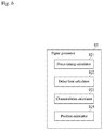
- FIG. 6 is a block diagram schematically illustrating a signal processor according to the first embodiment
- FIG. 7 provides graphs illustrating a drive signal, benchmark signal, measurement-side focus position, and measurement system photodetection signal according to the first embodiment
- FIG. 8 provides graphs illustrating a drive signal, benchmark signal, reference-side focus position, and reference system photodetection signal according to the first embodiment
- FIG. 9 provides graphs describing changes in refractive index characteristics of the liquid lens apparatus
- FIG. 10 illustrates a calibration table according to the first embodiment
- FIG. 11 is a schematic view illustrating a non-contact displacement sensor according to a second embodiment of the present invention.
- FIG. 12 is a schematic view illustrating a non-contact displacement sensor according to a third embodiment of the present invention.
- FIG. 13 is a schematic view illustrating a non-contact displacement sensor according to a fourth embodiment of the present invention.
- FIG. 14 is a schematic view illustrating a non-contact displacement sensor according to a fifth embodiment of the present invention.
- FIG. 15 provides graphs illustrating a drive signal, benchmark signal, focus positions, and photodetection signal according to the fifth embodiment.
- a non-contact displacement sensor 1 is configured to include a liquid lens apparatus 2 in which a refractive index periodically changes, and the non-contact displacement sensor 1 measures a positional change of a surface of a measured object W that is arranged intersecting with an optical axis OA 1 that runs through the liquid lens apparatus 2 .
- the non-contact displacement sensor 1 is configured so as to measure the positional change of the surface of the measured object W while measuring characteristics of the liquid lens apparatus 2 , and inhibits the influence of changes in the characteristics of the liquid lens apparatus 2 on measurement results for the measured object W.
- the non-contact displacement sensor 1 includes a measurement system 3 that measures the positional change of the measured object W.
- the measurement system 3 is provided with a measurement light source 31 that emits measurement light, an optical system (a collimating lens 32 and an optical guide 4 ) that forms an optical path for the measurement light, a measurement-side objective lens 33 configuring a measurement-side variable focal length lens 101 together with the liquid lens apparatus 2 , and a measurement light photodetector 34 receiving the measurement light that is reflected by the measured object W.
- the non-contact displacement sensor 1 includes a reference system 5 that measures characteristics of the liquid lens apparatus 2 .
- the reference system 5 is provided with a reference light source 51 that emits reference light, an optical system (a collimating lens 52 , an optical guide 6 , and beam splitters 53 and 54 ) that forms an optical path for the reference light, a reference-side objective lens 55 configuring a reference-side variable focal length lens 102 together with the liquid lens apparatus 2 , a reference light optical path portion (reference light optical system) 7 where the reference light that passes through the reference-side objective lens 55 is incident, and a reference light photodetector 56 receiving the reference light that arrives via the reference light optical path portion 7 .
- the measurement light source 31 and the reference light source 51 are equivalent to light sources according to the present disclosure.
- the measurement light photodetector 34 and the reference light photodetector 56 are equivalent to photodetectors according to the present disclosure.
- the non-contact displacement sensor 1 is provided with a lens controller 8 that controls operations of the liquid lens apparatus 2 and a controller 9 that operates the lens controller 8 .
- the controller 9 also imports and processes photodetection signals Sm and Sr, and calculates a position of the surface of the measured object W on the optical axis OA 1 while measuring the characteristics of the liquid lens apparatus 2 .
- the liquid lens apparatus 2 is configured with a liquid lens system on an interior thereof, and a refractive index changes in response to an input drive signal Cf.
- the drive signal Cf is a sinusoidal AC signal of a frequency that generates a standing wave in the liquid lens apparatus 2 .
- a focus position Pf 2 formed by the reference-side variable focal length lens 102 (which is an assembly of the liquid lens apparatus 2 and the reference-side objective lens 55 ), while based on a focal point position of the reference-side objective lens 55 , can be changed as desired by changing the refractive index of the liquid lens apparatus 2 .
- the lens apparatus 2 includes a hollow cylindrical case 21 , and a hollow cylindrical oscillating member 22 is installed on an interior of the case 21 .
- the oscillating member 22 is supported by spacers 29 that are made of an elastomer and are disposed between an outer circumferential surface 23 of the oscillating member 22 and an inner circumferential surface 24 of the case 21 .
- the oscillating member 22 is a member where a piezoelectric material is formed in a hollow cylindrical shape.
- the oscillating member 22 oscillates in a thickness direction due to an AC voltage of the drive signal Cf being applied between the outer circumferential surface 23 and the inner circumferential surface 24 .
- the interior of the case 21 is filled with a highly transparent liquid 25 , the entire oscillating member 22 is immersed in the liquid 25 , and an inner side of the hollow cylindrical oscillating member 22 is filled with the liquid 25 .
- the AC voltage of the drive signal Cf is adjusted to a frequency that generates a standing wave in the liquid 25 on the inner side of the oscillating member 22 .
- FIGS. 3A to 3C in the liquid lens apparatus 2 , when the oscillating member 22 is oscillated, a standing wave arises in the interior liquid 25 and concentric circular regions arise in which the refractive index alternates (see FIGS. 3A and 3B ). At this point, a relationship between a distance from a center axis line of the liquid lens apparatus 2 (radius) and the refractive index of the liquid 25 is as shown by a refractive index distribution R illustrated in FIG. 3C .
- an amplitude of the refractive index distribution R is at its largest, the liquid lens apparatus 2 causes transiting light to converge, and the focus position Pf 1 is the closest to the measurement-side Objective lens 33 .
- the refractive index distribution R is flat, the liquid lens apparatus 2 allows transiting light to transit unaffected, and the focus position Pf 1 is at a standard value.
- the amplitude of the refractive index distribution R is at its largest at the opposite pole from that of FIG. 4A , the liquid lens apparatus 2 causes transiting light to diffuse, and the focus position Pf 1 is at its farthest from the measurement-side objective lens 33 .
- the drive signal Cf is a sinusoidal AC signal
- the focus position Pf 1 fluctuates sinusoidally, as in a fluctuation waveform Mf 1 in FIGS. 4A to 4E .
- the measurement-side variable focal length lens 101 may also be cases where, in the measurement-side variable focal length lens 101 , a principal point of the measurement-side variable focal length lens 101 fluctuates, whereby the focus position Pf 1 changes while the focal length (distance from the principal point of the measurement-side variable focal length lens 101 to the focus position Pf 1 ) remains constant.
- the measurement-side variable focal length lens 101 is described above, but a similar description is also applicable for the reference-side variable focal length lens 102 .
- the measurement light source 31 is a laser light source, for example, and emits measurement light.
- the optical guide 4 includes a fiber splitter 41 and optical fibers 42 to 44 .
- the fiber splitter 41 has an optical path where a first end portion of each of the optical fibers 42 to 44 are connected, and is configured so as to guide the light that is incident from the optical fiber 42 to the optical fiber 43 , and guide the light that is incident from the optical fiber 43 to the optical fiber 44 .
- a second end portion of the optical fiber 42 is connected to the measurement light source 31 . Therefore, the measurement light emitted from the measurement light source 31 transits the optical fiber 42 , the fiber splitter 41 , and the optical fiber 43 , and is emitted from an end face 43 e of the second end portion of the optical fiber 43 . That is, the end face 43 e of the optical fiber 43 carries out operations as a point light source of measurement light.
- the second end portion of the optical fiber 44 is connected to the measurement light photodetector 34 . Therefore, the measurement light incident on the end face 43 e of the optical fiber 43 transits the optical fiber 43 , the fiber splitter 41 , and the optical fiber 44 , and is incident on the measurement light photodetector 34 .
- the end face 43 e of the optical fiber 43 is positioned at a focal point on a rear side of the collimating lens 32 .
- the end face 43 e of the optical fiber 43 is arranged at a position that creates a conjugate relationship with respect to the focus position Pf 1 formed by the measurement-side variable focal length lens 101 , on the optical axis OA 1 .
- the collimating lens 32 is positioned on the optical axis OA 1 , converts the measurement light emitted from the end face 43 e of the optical fiber 43 into parallel light, and causes the light to strike the liquid lens apparatus 2 . Also, the collimating lens 32 collects the measurement light that is reflected by the measured object W and passes through the liquid lens apparatus 2 again.
- the measurement-side objective lens 33 is configured by a known convex lens or lens group, is positioned between the liquid lens apparatus 2 and the measured object W on the optical axis OA 1 , and, together with the liquid lens apparatus 2 , configures the measurement-side variable focal length lens 101 described above.
- the measured object W is arranged inside a variable range VR 1 of the focus position Pf 1 formed by the measurement-side variable focal length lens 101 .
- the measurement-side objective lens 33 is not made integral with other structures, but instead is configured to be swappable for separate measurement-side objective lenses 33 having different powers of magnification.
- the measurement light photodetector 34 may be a photomultiplier tube or a photodiode, for example, and is connected to the second end portion of the optical fiber 44 .
- the measurement light photodetector 34 receives the measurement light incident via the optical fiber 44 and outputs a photodetection signal Sm in accordance with the intensity of the received light.
- the measurement light emitted from the end face 43 e of the optical fiber 43 is collimated along the optical axis OA 1 by the collimating lens 32 , after which the light is emitted at the measured object W via the measurement-side variable focal length lens 101 .
- the measurement light reflected by the measured object W is collected by the collimating lens 32 after once again transiting the measurement-side variable focal length lens 101 .
- the focus position Pf 1 formed by the measurement-side variable focal length lens 101 periodically changes on the optical axis OA 1 .
- the measurement light incident on the measurement light photodetector 34 is maximized when the focus position Pf 1 coincides with the surface of the measured object W.
- the photodetection signal Sm output from the measurement light photodetector 34 exhibits a peak when the focus position Pf 1 coincides with the surface of the measured object W.
- the reference light source 51 is a laser light source, for example, and emits reference light having a different wavelength from the measurement light.
- the optical guide 6 includes a fiber splitter 61 and optical fibers 62 to 64 .
- the fiber splitter 61 has an optical path where a first end portion of each of the optical fibers 62 to 64 are connected, and is configured so as to guide the light that is incident from the optical fiber 62 to the optical fiber 63 , and guide the light that is incident from the optical fiber 63 to the optical fiber 64 .
- a second end portion of the optical fiber 62 is connected to the reference light source 51 . Therefore, the reference light emitted from the reference light source 51 transits the optical fiber 62 , the fiber splitter 61 , and the optical fiber 63 , and is emitted from an end face 63 e of the second end portion of the optical fiber 63 . That is, the end face 63 e of the optical fiber 63 carries out operations as a point light source of reference light.
- the second end portion of the optical fiber 64 is connected to the reference light photodetector 56 .
- the measurement light incident on the end face 63 e of the optical fiber 63 transits the optical fiber 63 , the fiber splitter 61 , and the optical fiber 64 , and is incident on the reference light photodetector 56 .
- the end face 63 e of the optical fiber 63 is positioned at a focal point on a rear side of the collimating lens 52 on an optical axis OA 2 .
- the end face 63 e of the optical fiber 63 is arranged at a position that creates a conjugate relationship with respect to the focus position Pf 2 formed by the reference-side variable focal length lens 102 .
- the collimating lens 52 is positioned on the optical axis OA 2 , converts the measurement light emitted from the end face 63 e of the optical fiber 63 into parallel light, and causes the light to strike the liquid lens apparatus 2 via the beam splitter 53 . Also, the collimating lens 52 collects the reference light that passes by way of the reference light optical path portion 7 and through the liquid lens apparatus 2 again.
- the beam splitters 53 and 54 may be beam splitters or dichroic mirrors, for example, and act to allow measurement light to pass through and also to reflect reference light.
- the beam splitters 53 and 54 are arranged so as to have the liquid lens apparatus 2 therebetween on the optical axis OA 1 , and the splitters form optical axes OA 2 and OA 3 , which are split off from the optical axis OA 1 before and after the liquid lens apparatus 2 , respectively.
- the reference-side objective lens 55 is configured by a known convex lens or lens group, is positioned between the liquid lens apparatus 2 and the reference light optical path portion 7 on the optical axis OA 3 , and, together with the liquid lens apparatus 2 , configures the reference-side variable focal length lens 102 described above.
- the reference light optical path portion 7 is provided with a partial reflecting mirror 71 and a reflecting mirror 72 on the optical axis OA 3 , each mirror having a mutually distinct optical path length measured from the reference-side objective lens 55 .
- the partial reflecting minor 71 is arranged on a side closer to the reference-side objective lens 55 , and includes a first reference surface 71 s (first reference portion) that reflects a portion of the reference light and also allows another portion thereof to pass through.
- the reflecting minor 72 is arranged on a side farther from the reference-side objective lens 55 , and includes a second reference surface 72 s (second reference portion) that reflects the reference light that passes through the partial reflecting minor 71 .
- a known value is defined for an optical path length between the first reference surface 71 s and the second reference surface 72 s (that is, for an optical path length difference L, which is the difference between the optical path length running from the reference-side objective lens 55 to the first reference surface 71 s and the optical path length running from the reference-side objective lens 55 to the second reference surface 72 s ).
- the position of each of the first reference surface 71 s and the second reference surface 72 s can be set as desired, so long as the position is within a variable range VR 2 of the focus position Pf 2 formed by the reference-side variable focal length lens 102 .
- the reference light photodetector 56 may be a photomultiplier tube or a photodiode, for example, and is connected to the second end portion of the optical fiber 64 .
- the reference light photodetector 56 receives the reference light incident via the optical fiber 64 and outputs a photodetection signal Sr in accordance with the intensity of the received light.
- the reference light emitted from the end face 63 e of the optical fiber 63 is collimated along the optical axis OA 2 by the collimating lens 52 , after which the light is bent toward the object side of the optical axis OA 1 direction by the beam splitter 53 . Then, the reference light passes through the liquid lens apparatus 2 and is bent in the optical axis OA 3 direction by the beam splitter 54 , after which the light enters the reference light optical path portion 7 while being collected by the reference-side objective lens 55 .
- the reference light that enters the reference light optical path portion 7 is split into a first reference light that is reflected by the first reference surface 71 s and a second reference light that passes through the first reference surface 71 s and is then reflected by the second reference surface 72 s .
- the first and second reference lights that are reflected by the first reference surface 71 s or the second reference surface 72 s follow the reverse path, and then are collected by the collimating lens 52 .
- the focus position Pf 2 formed by the reference-side variable focal length lens 102 periodically changes in the optical axis OA 3 direction.
- the reference light incident on the reference light photodetector 56 is maximized when the focus position Pf 2 coincides with either the first reference surface 71 s or the second reference surface 72 s .
- the photodetection signal Sr output from the reference light photodetector 56 exhibits a peak when the focus position Pf 2 coincides with either the first reference surface 71 s or the second reference surface 72 s.
- the lens controller 8 is configured as a control device that controls the operation of the liquid lens apparatus 2 and includes a drive signal outputter 81 outputting the sinusoidal drive signal Cf to the liquid lens apparatus 2 .
- the lens controller 8 includes a benchmark signal outputter 82 outputting, to the controller 9 , a pulse-like benchmark signal Sc that is synchronized with the period of the drive signal Cf.
- the timing of the output of the benchmark signal Sc relative to the period of the drive signal Cf can be defined as desired, but in the present embodiment, the benchmark signal Sc rises once for every two times that the drive signal Cf intersects level 0 (in FIG. 7 , for example, at points in time where the fluctuation waveform Mf 1 of the focus position Pf 1 reaches a positive peak).
- the controller 9 is configured by a personal computer or the like that includes, for example, a central processing unit (CPU) and memory.
- the controller 9 achieves expected functionality by running predetermined software, and includes a lens settings portion 91 that defines settings of the lens controller 8 , and a signal processor 92 that processes various input signals.
- the controller 9 includes a memory 93 configured by a memory and the like.
- the lens settings portion 91 defines, for example, settings for the frequency, amplitude, and maximum drive voltage of the drive signal Cf that is output by the lens controller 8 .
- a number of changes in resonance may be changed according to a change in ambient temperature, for example. Therefore, the lens settings portion 91 executes operations to change the frequency of the drive signal Cf in real-time through feedback control and to stabilize the liquid lens apparatus 2 .
- the photodetection signal Sm is input from the measurement light photodetector 34
- the photodetection signal Sr is input from the reference light photodetector 56
- the benchmark signal Sc is input from the lens controller 8 .
- the signal processor 92 calculates a measured object position Zcalc by performing processing based on the input photodetection signals Sm and Sr. Therefore, as illustrated in FIG. 6 , the signal processor 92 carries out operations as a focus timing calculator 921 , a delay time calculator 922 , a characteristics calculator 923 , and a position calculator 924 .
- a calibration table 94 that is prepared in advance using a target or the like is stored in the memory 93 .
- the calibration table 94 associates the measured object position Zcalc, which is a computed value obtained by signal processing (computed value related to a position Pw of the measured object W on the optical axis OA 1 ), with a measured object position Z, which serves as a display value for measurement results.
- the apparatus when the sinusoidal drive signal Cf is input to the liquid lens apparatus 2 , the apparatus is synchronized with the period of the drive signal Cf, and the benchmark signal Sc is output in a pulse. Furthermore, when the sinusoidal drive signal Cf is input to the liquid lens apparatus 2 , by periodically changing the refractive index of the liquid lens apparatus 2 , the focus positions Pf 1 and Pf 2 formed by the variable focal length lenses 101 and 102 , respectively, are each changed periodically, synchronized with the drive signal Cf.
- FIG. 7 illustrates an example of the position Pw of the measured object W on the optical axis OA 1 for a measured object W located within the variable range of the focus position Pf 1 .
- the photodetection signal Sm exhibits a peak when the focus position Pf 1 coincides with the position Pw of the measured object W, and exhibits two peaks per cycle of the drive signal Cf.
- an amount of time from the point in time when the benchmark signal Sc rises to each peak time of the first and second peaks of the photodetection signal Sm (measurement-side focus timing Tm) is expressed as a delay time ⁇ tm 1 and ⁇ tm 2 .
- processing is performed using one value from the delay times ⁇ tm 1 and ⁇ tm 2 (for example, ⁇ tm 1 ), but in the modifications described hereafter, both of the delay times ⁇ tm 1 and ⁇ tm 2 may be used, as well.
- FIG. 8 illustrates an example of positions Pr 1 and Pr 2 for the first reference surface 71 s and the second reference surface 72 s , respectively, located within the variable range of the focus position Pf 2 .
- the photodetection signal Sr exhibits a peak when the focus position Pf 1 coincides with one of the positions Pr 1 and Pr 2 of the first reference surface 71 s and the second reference surface 72 s , respectively, and exhibits four peaks per cycle of the drive signal Cf.
- an amount of time from the point in time when the benchmark signal Sc rises to each peak time of the first through fourth peaks of the photodetection signal Sr is expressed as a delay time ⁇ tr 1 , ⁇ tr 2 , ⁇ tr 3 , and ⁇ tr 4 .
- the first and fourth peak times of the photodetection signal Sr are each equivalent to a reference-side focus timing Tr where the focus position Pf 2 coincides with the first reference surface 71 s (first reference-side focus timing).
- the second and third peak times of the photodetection signal Sr are each equivalent to a reference-side focus timing Tr where the focus position Pf 2 coincides with the second reference surface 72 s (second reference-side focus timing).
- the liquid lens apparatus 2 is influenced by the passage of time, changes in temperature, and the like, and accordingly the refractive index characteristics of the liquid lens apparatus 2 change, and the variable ranges VR 1 and VR 2 , for example, of the focus positions Pf 1 and Pf 2 of the variable focal length lenses 101 and 102 , respectively, change.
- the fluctuation waveforms Mf 1 and Mf 2 of the focus positions Pf 1 and Pf 2 each change from an ideal waveform calculated from the drive signal Cf.
- an ideal fluctuation waveform Mf 2 I calculated from the drive signal Cf is illustrated with a dashed line and an actual fluctuation waveform Mf 2 subsequent to the refractive index characteristics of the liquid lens apparatus 2 changing due to a change in temperature or the like is illustrated with a solid line.
- the actual fluctuation waveform Mf 2 has a phase delay ⁇ d and a deviation B relative to the ideal fluctuation waveform Mf 2 I.
- the deviation B is equivalent to an amount of offset of a center position Pc of the variable range VR 2 of the focus position Pf 2 .
- the refractive index characteristics of the liquid lens apparatus 2 are calculated as an amplitude A, the deviation B, and the phase delay ⁇ d of the fluctuation waveform Mf 2 of the focus position Pf 2 .
- the optical path length difference L between the first reference surface 71 s and the second reference surface 72 s relative to the reference-side objective lens 55 , and a frequency ⁇ of the drive signal Cf express the amplitude A, the deviation B, and the phase delay ⁇ d of the fluctuation waveform Mf 2 .
- the amplitude A, the deviation B, and the phase delay ⁇ d of the fluctuation waveform Mf 2 which are unknown values, are respectively expressed by the following equations (5), (6), and (7) (or (8)).
- A L / ⁇ cos[ ⁇ ( ⁇ tr 3 ⁇ tr 2)] ⁇ cos[ ⁇ ( ⁇ tr 4 ⁇ tr 1)] ⁇ Equation (5)
- B ( L/ 2) ⁇ cos[ ⁇ ( ⁇ tr 3 ⁇ tr 2)]+cos[ ⁇ ( ⁇ tr 4 ⁇ tr 1)] ⁇ / ⁇ cos[ ⁇ ( ⁇ tr 3 ⁇ tr 2)] ⁇ cos[ ⁇ ( ⁇ tr 4 ⁇ tr 1)] ⁇ Equation (6)
- ⁇ d ⁇ [1 ⁇ ( ⁇ tr 1 + ⁇ tr 4)] Equation (7)
- ⁇ d ⁇ [1 ⁇ ( ⁇ tr 2 + ⁇ tr 3)] Equation (8)
- the signal processor 92 acquires the benchmark signal Sc and the photodetection signals Sm and Sr illustrated in FIGS. 7 and 8 .
- the focus timing calculator 921 calculates the peak time of the photodetection signal Sm as the measurement-side focus timing Tm. Similarly, the focus timing calculator 921 calculates the peak time of the photodetection signal Sr as the reference-side focus timing Tr.
- the delay time calculator 922 calculates the delay times ⁇ tm 1 and ⁇ tm 2 , which are the amount of time from the point in time when the benchmark signal Sc rises to the measurement-side focus timing Tm, and the delay times ⁇ tr 1 , ⁇ tr 2 , ⁇ tr 3 , and ⁇ tr 4 , which are the amount of time from the point in time when the benchmark signal Sc rises to the reference-side focus timing Tr.
- the delay time calculator 922 may also use a clock signal or the like.
- the characteristics calculator 923 uses the calculated delay times ⁇ tr 1 , ⁇ tr 2 , ⁇ tr 3 , and ⁇ tr 4 for the reference-side focus timing Tr to calculate the amplitude A, the deviation B, and the phase delay ⁇ d of the fluctuation waveform Mf 2 as refractive index characteristics of the liquid lens apparatus 2 , based on equations (5), (6), and (7) (or (8)) above.
- the position calculator 924 uses the calculated delay time ⁇ tm 1 of the measurement-side focus timing Tm to calculate a phase ⁇ mp 1 of the measurement-side focus timing Tm relative to the period of the drive signal Cf, based on the following equation (9).
- ⁇ mp 1 2 ⁇ tm 1 Equation (9)
- the position calculator 924 uses the calculated phase ⁇ mp 1 of the measurement-side focus timing Tm and the phase delay ⁇ d to find a phase ⁇ m 1 of the measurement-side focus timing Tm that is corrected by the refractive index characteristics of the liquid lens apparatus 2 , based on the following equation (10).
- ⁇ m 1 ⁇ mp 1 ⁇ d Equation (10)
- the position calculator 924 uses the amplitude A and the deviation B of the fluctuation waveform Mf 2 , a focal length Fr of the reference-side objective lens 55 , and a focal length Fm of the measurement-side objective lens 33 to calculate the measured object position Zcalc, based on the following equation (11).
- Z calc ( Fm/Fr )( B+A cos ⁇ m 1) Equation (11)
- the position calculator 924 finds the measured object position Z that corresponds to the measured object position Zcalc calculated by equation (11) above. Specifically, the position calculator 924 calculates the measured object position Z that corresponds to the measured object position Zcalc using a linear squares method or the like, based on two measured object positions Zk having the measured object position Zcalc therebetween and measured object positions Zcalc,k that correspond to the measured object positions Zk.
- the non-contact displacement sensor 1 can calculate the measured object position Z, which is a value showing the position Pw of the measured object W on the optical axis OA 1 .
- the signal processor 92 may perform the above-noted processing every fixed amount of time, and the measured object position Z obtained may be successively stored in the memory 93 .
- the calibration table 94 Prior to carrying out the displacement measurement described above, the calibration table 94 is prepared using the non-contact displacement sensor 1 .
- the measured object positions Zcalc,k are calculated by performing the above-described measurement with the non-contact displacement sensor 1 .
- the calibration table 94 illustrated in FIG. 10 is prepared in the above way.
- the calibration table 94 is preferably prepared for each of a plurality of types of magnification power that are prepared as the measurement-side objective lens 33 .
- the embodiment is configured to switch between the calibration tables 94 being referenced.
- the measurement-side variable focal length lens 101 is configured by the liquid lens apparatus 2 and the measurement-side objective lens 33 . Therefore, the present embodiment does not require use of a lens drive mechanism and a scale that are required structures in a conventional laser displacement sensor.
- the measured object position Zcalc can be calculated using the photodetection signal Sm, and therefore, the processing of a large amount of data that is performed in a conventional chromatic point sensor is unnecessary.
- the liquid lens apparatus 2 configuring the measurement-side variable focal length lens 101 also configures, together with the reference-side objective lens 55 , the reference-side variable focal length lens 102 , and the refractive index characteristics of the liquid lens apparatus 2 are calculated using the photodetection signal Sr for the reference light. Therefore, by performing correction in accordance with a change in the refractive index characteristics, changes in the measurement results due to the passage of time or environmental changes such as temperature can be inhibited (improved robustness). Accordingly, the present embodiment provides a non-contact displacement sensor 1 in which the configuration and processing can be simplified, and in which measurement accuracy is improved.
- the non-contact displacement sensor 1 is further provided with the benchmark signal outputter 82 that outputs the benchmark signal Sc, which is synchronized to the drive signal Cf.
- the characteristics calculator 923 calculates the refractive index characteristics of the liquid lens apparatus 2 based on the delay times ⁇ tr 1 to ⁇ tr 4 of the reference-side focus timing Tr relative to the benchmark signal Sc.
- the position calculator 924 calculates the phase ⁇ m 1 of the measurement-side focus timing Tm relative to the period of the drive signal Cf based on the delay time ⁇ tm 1 of the measurement-side focus timing Tm relative to the benchmark signal Sc. Therefore, the refractive index characteristics of the liquid lens apparatus 2 and the phase ⁇ m 1 of the measurement-side focus timing Tm can be easily found even without performing complex computation.
- the reference light optical path portion 7 is provided with the partial reflecting mirror 71 having the first reference surface 71 s (first reference portion), which reflects a portion of the reference light, and the reflecting mirror 72 having the second reference surface 72 s (second reference portion), which reflects the reference light that passes through the first reference surface 71 s .
- first reference portion first reference portion
- second reference portion second reference portion
- the non-contact displacement sensor 1 As light sources according to the present invention, the non-contact displacement sensor 1 according to the present embodiment is provided with the measurement light source 31 which emits measurement light and the reference light source 51 which emits reference light, and as photodetectors according to the present invention, the non-contact displacement sensor 1 is provided with the measurement light photodetector 34 and the reference light photodetector 56 . Therefore, the photodetection signals Sm and Sr can be readily distinguished, and thus computation in the signal processor 92 is simplified.
- the non-contact displacement sensor 1 is capable of switching between magnification powers of the measurement-side objective lens 33 , which is difficult in the conventional technology.
- a laser displacement sensor has an objective lens incorporated into a lens drive mechanism
- a chromatic point sensor has an objective lens modularized along with a special lens group that disperses white light using axial chromatic aberration. Therefore, in the laser displacement sensor and the chromatic point sensor, it is difficult to swap out only the objective lens for a separate one having a different magnification power, and a separate device must be prepared in order to make measurements in a different measurement range and resolution.
- the non-contact displacement sensor 1 there is no need to integrate the measurement-side objective lens 33 with other structures, as in the prior art. Therefore, a configuration can be easily provided which is capable of switching the measurement-side objective lens 33 for a separate measurement-side objective lens 33 having a different magnification power.
- a confocal optical system is configured in both the measurement system 3 and the reference system 5 in order to detect the measurement-side focus timing Tm and the reference-side focus timing Tr. Therefore, compared to cases using other focal point detection methods, the measurement accuracy can be further improved since the present embodiment is less likely to be affected by the inclination of the surface of the measured object W, measurement accuracy for surface characteristics such as roughness, and so on.
- the light sources (measurement light source 31 and reference light source 51 ) and the photodetectors (measurement light photodetector 34 and reference light photodetector 56 ), which are sources of heat, can be placed away from a portion that serves as a measurement head, and thermal effects on the measurement can be reduced.
- the end face 43 e of the optical fiber 43 and the end face 63 e of the optical fiber 63 each play both roles as a point light source and a pinhole for detection in the confocal optical system, and therefore, the number of adjustment steps during manufacturing can be significantly reduced.
- the phase ⁇ m 1 of the measurement-side focus timing Tm is calculated by performing the calculations of equations (9) and (10), given above, using the delay time ⁇ tm 1 of the measurement-side focus timing Tm, but the present invention is not limited to this.
- a phase ⁇ m 2 of the measurement-side focus timing Tm may also be calculated by performing calculations similar to equations (9) and (10), given above, using the delay time ⁇ tm 2 of the measurement-side focus timing Tm.
- equations (9) and (10) according to the first embodiment may be omitted and the phase ⁇ m 1 of the measurement-side focus timing Tm may also be calculated by performing a calculation according to equation (12), given below, using the delay times ⁇ tm 1 and ⁇ tm 2 of the measurement-side focus timing Tm.
- ⁇ is the frequency of the drive signal Cf.
- ⁇ m 1 ⁇ [1 ⁇ ( ⁇ tm 2 ⁇ tm 1)] Equation (12)
- the computation step in the first embodiment can be partially omitted, and therefore measurement can be accelerated due to shortening the computation time.
- ⁇ tm 2 ⁇ tm 1 is equivalent to the time difference between the two measurement-side focus timings Tm that appear during one cycle of the drive signal Cf. Therefore, instead of measuring the delay times ⁇ tm 1 and ⁇ tm 2 of the measurement-side focus timing Tm, the time difference may be measured directly.
- measurement begins from the point in time when the benchmark signal Sc rises, but measurement may also begin from the point in time when the benchmark signal Sc falls.
- the same may apply to the delay times ⁇ tr 1 to ⁇ tr 4 of the reference-side focus timing Tr, as well.
- the amplitude A, the deviation B, and the phase delay ⁇ d of the fluctuation waveform Mf 2 of the focus position Pf 2 are calculated based on the delay times ⁇ tr 1 to ⁇ tr 4 of the reference-side focus timing Tr, but the present invention is not limited to this and these values may also be found by computation or the like based on the sine wave exhibited by the drive signal Cf.
- the phase ⁇ m 1 of the measurement-side focus timing Tm is calculated based on the delay times ⁇ tm 1 and ⁇ tm 2 of the measurement-side focus timing Tm, but the present invention is not limited to this and this value may also be found by computation or the like based on the sine wave exhibited by the drive signal Cf.
- a non-contact displacement sensor 1 A according to a second embodiment is described with reference to FIG. 11 .
- identical reference numerals are used for structures similar to those in the first embodiment and a detailed description thereof is omitted.
- a pinhole-type confocal optical system is configured in each of the measurement system 3 and the reference system 5 .
- the non-contact displacement sensor 1 A is provided with a beam splitter 45 and pinhole members 46 and 47 instead of the optical guide 4 according to the first embodiment.
- the non-contact displacement sensor 1 A is provided with a beam splitter 65 and pinhole members 66 and 67 instead of the optical guide 6 according to the first embodiment.
- the beam splitter 45 is configured so as to bend the measurement light emitted from the measurement light source 31 toward the collimating lens 32 , and so as to allow light that is incident from the collimating lens 32 side to pass through to the measurement light photodetector 34 side.
- the pinhole member 46 is arranged between the beam splitter 45 and the measurement light source 31 . Due to the measurement light source 31 emitting the measurement light via the pinhole of the pinhole member 46 , the pinhole serves as a point light source.
- the pinhole member 47 is arranged between the beam splitter 45 and the measurement light photodetector 34 and has a pinhole that is arranged at the focal point on the rear side of the collimating lens 32 . The measurement light that is focused at and reflected by the surface of the measured object W passes through the pinhole of the pinhole member 47 , and then is incident on the measurement light photodetector 34 .
- the beam splitter 65 is configured so as to bend the measurement light emitted from the reference light source 51 toward the collimating lens 52 , and so as to allow light that is incident from the collimating lens 52 side to pass through to the reference light photodetector 56 side.
- the pinhole member 66 is arranged between the beam splitter 65 and the reference light source 51 . Due to the reference light source 51 emitting the reference light via the pinhole of the pinhole member 66 , the pinhole serves as a point light source.
- the pinhole member 67 is arranged between the beam splitter 65 and the reference light photodetector 56 and has a pinhole that is arranged at the focal point on the rear side of the collimating lens 52 . The reference light that is focused at and reflected by the surface of the measured object W passes through the pinhole of the pinhole member 67 , and then is incident on the reference light photodetector 56 .
- non-contact displacement sensor 1 A similarly to the first embodiment, the configuration and processing can be simplified, and measurement accuracy can be improved. Also, according to the non-contact displacement sensor 1 A, the optical fibers 42 to 44 and 62 to 64 of the first embodiment are omitted, and therefore there is no need to provide room to run these optical fibers and the non-contact displacement sensor 1 A overall can be made more compact.
- a non-contact displacement sensor 1 B according to a third embodiment is described with reference to FIG. 12 .
- identical reference numerals are used for structures similar to those in the first embodiment and a detailed description thereof is omitted.
- the non-contact displacement sensor 1 B is provided with a reference light optical path portion 7 B having a different configuration from that of the reference light optical path portion 7 .
- the reference light optical path portion 7 B is provided with a reference light optical path splitter 73 that splits the reference light, an optical fiber 74 (first optical fiber) that is arranged further along in a direction traveled by a first reference light split by the reference light optical path splitter 73 , and an optical fiber 75 (second optical fiber) that is arranged further along in a direction traveled by a second reference light split by the reference light optical path splitter 73 .
- the reference light optical path splitter 73 is a beam splitter such as a half mirror, for example.
- the reference light that transits through the reference-side objective lens 55 is split into the first reference light, which transits through the reference light optical path splitter 73 , and the second reference light, which is reflected by the reference light optical path splitter 73 .
- the reference light optical path splitter 73 is arranged on the optical axis OA 3 and forms an optical axis OA 4 that branches off from the optical axis OA 3 .
- a first reference end face 74 e (first reference portion), which is an end face of a first end portion of the optical fiber 74 , is arranged on the optical axis OA 3 .
- a second reference end face 75 e (second reference portion), which is an end face of a first end portion of the optical fiber 75 , is arranged on the optical axis OA 4 .
- the position of each of the first reference end face 74 e and the second reference end face 75 e can be set as desired, so long as the position is within a variable range of the focus position Pf 2 formed by the reference-side variable focal length lens 102 .
- the optical path length difference L is the difference between the optical path length running from the reference-side objective lens 55 to the first reference surface 74 e and the optical path length running from the reference-side objective lens 55 to the second reference surface 75 e .
- the optical path length difference L is a length obtained by taking the difference between a distance La on the optical axis OA 3 from the reference light optical path splitter 73 to the first reference end face 74 e of the optical fiber 74 and a distance Lb on the optical axis OA 4 from the reference light optical path splitter 73 to the second reference end face 75 e of the optical fiber 75 .
- the reference light optical path portion 7 B is further provided with an optical fiber 76 , the first end portion of which is connected to the reference light photodetector 56 , and a fiber splitter 77 , to which is connected the second end portion of each of the optical fibers 74 to 76 .
- the fiber splitter 77 is configured such that the light that is incident from each of the optical fibers 74 and 75 is guided to the optical fiber 76 .
- the reference light incident on the reference light optical path portion 7 B is split into the first reference light, which transits through the reference light optical path splitter 73 , and the second reference light, which is reflected by the reference light optical path splitter 73 .
- the first reference light advances toward the first reference end face 74 e of the optical fiber 74
- the second reference light advances toward the second reference end face 75 e of the optical fiber 75 .
- the focus position Pf 2 formed by the reference-side variable focal length lens 102 periodically changes along each of the optical axis OA 3 and the optical axis OA 4 .
- the focus position Pf 2 coincides with the first reference end face 74 e
- the first reference light that has been collected is incident on the first reference end face 74 e
- the optical fibers 74 and 76 is incident on the reference light photodetector 56 .
- the reference light incident on the reference light photodetector 56 is maximized when the focus position Pf 2 coincides with either the first reference end face 74 e or the second reference end face 75 e . That is, the photodetection signal Sm output from the reference light photodetector 56 exhibits a peak when the focus position Pf 2 coincides with either the first reference end face 74 e or the second reference end face 75 e.
- the non-contact displacement sensor 1 B is provided with an optical guide 6 B having a different configuration from that of the optical guide 6 .
- the optical guide 6 B has an optical fiber 68 , a first end portion of which is connected to the reference light source 51 .
- the reference light emitted from the reference light source 51 transits through the optical fiber 68 , and is emitted from an end face 68 e of a second end portion of the optical fiber 68 . That is, the end face 68 e of the optical fiber 68 carries out operations as a point light source of reference light.
- the end face 68 e of the optical fiber 68 can be arranged at any desired position on the optical axis OA 2 because the end face 68 e does not receive any reference light.
- non-contact displacement sensor 1 B similarly to the first embodiment, the configuration and processing can be simplified, and measurement accuracy can be improved. Also, according to the non-contact displacement sensor 1 B, the partial reflecting mirror 71 and the reflecting mirror 72 according to the first embodiment can be omitted, and therefore costs can be lowered by reducing the number of optical components.
- the reference light optical path portion 7 B according to the third embodiment may also be provided with a pinhole member arranged on each of the optical axes OA 3 and OA 4 and a reference light photodetector arranged on the rear side of each of the pinhole members.
- the pinhole of each pinhole member is equivalent to, respectively, the first reference portion and the second reference portion according to the present invention.
- the optical guides 4 and 6 B may be swapped out for a configuration utilizing a pinhole member, similar to the second embodiment.
- the beam splitter 54 when the beam splitter 54 splits the light emitted from the measurement light source 31 into measurement light and reference light, the reference light source 51 , the optical guide 6 B, the collimating lens 52 , and the beam splitter 53 may also be omitted.
- a non-contact displacement sensor 1 C according to a fourth embodiment is described with reference to FIG. 13 .
- identical reference numerals are used for structures similar to those in the first embodiment and a detailed description thereof is omitted.
- the collimating lenses 32 and 52 are omitted in the measurement system 3 and the reference system 5 , respectively, and a finite correction optical system is configured.
- the measurement system 3 configured in this way, the measurement light reflected by the measured object W is imaged by the measurement-side objective lens 33 .
- the end face 43 e of the optical fiber 43 is not positioned at the focal point on the rear side of the collimating lens 32 as in the first embodiment, but instead is arranged to the rear of a focal point on the rear side of the measurement-side objective lens 33 , at a position separated by a distance obtained by multiplying the imaging magnification power by the focal distance of the measurement-side objective lens 33 .
- the reference light that is reflected by either one of the first reference surface 71 s and the second reference surface 72 s is imaged by the reference-side objective lens 55 .
- the end face 63 e of the optical fiber 63 is not positioned at the focal point on the rear side of the collimating lens 52 as in the first embodiment, but instead is arranged to the rear of a focal point on the rear side of the reference-side objective lens 55 , at a position separated by a distance obtained by multiplying the imaging magnification power by the focal distance of the reference-side objective lens 55 .
- non-contact displacement sensor 1 C similarly to the first embodiment, the configuration and processing can be simplified, and measurement accuracy can be improved. In addition, in the non-contact displacement sensor 1 C, cost reduction can be achieved by omitting the collimating lenses 32 and 52 of the first embodiment.
- the finite correction optical system is configured for each of the measurement system 3 and the reference system 5 , but a finite correction optical system may also be configured in only one, while an infinite correction optical system (which includes the collimating lens 32 or 52 ) such as in the first embodiment is configured in the other.
- a non-contact displacement sensor 1 D according to a fifth embodiment is described with reference to FIG. 14 .
- identical reference numerals are used for structures similar to those in the first embodiment and a detailed description thereof is omitted.
- a light source 35 and a photodetector 36 are shared by the measurement system 3 and the reference system 5 .
- the reference light source 51 , the collimating lens 52 , the beam splitter 53 , the reference light photodetector 56 , and the optical guide 6 of the first embodiment are omitted.
- the measurement light source 31 and the measurement light photodetector 34 according to the first embodiment are configured as the light source 35 and the photodetector 36 that are shared by the measurement system 3 and the reference system 5 .
- the light emitted from the light source 35 transits the optical guide 4 , and is emitted from the end face 43 e of the optical fiber 43 .
- the light is collimated by the collimating lens 32 , after which the light transits through the liquid lens apparatus 2 and is split by the beam splitter 54 into measurement light and reference light. Similar to the first embodiment, the measurement light that passes through the beam splitter 54 is emitted at the measured object W, and after traveling the reverse path, the measurement light is collected by the collimating lens 32 .
- the measurement light that is reflected by the measured object W when the focus position Pf 1 coincides with the surface of the measured object W is incident on the end face 43 e of the optical fiber 43 , and via the optical guide 4 is incident on the photodetector 36 .
- the reference light that is reflected by the beam splitter 54 is incident on the reference light optical path portion 7 .
- the reference light that is reflected by the first reference surface 71 s or the second reference surface 72 s follows the reverse path, and then is collected by the collimating lens 32 .
- a photodetection signal Smr output from the photodetector 36 exhibits a peak when the focus position Pf 1 coincides with the surface of the measured object W, and when the focus position Pf 1 coincides with either the first reference surface 71 s or the second reference surface 72 s.
- the photodetection signal Smr is a signal in which the photodetection signals Sm and Sr according to the first embodiment are mixed together.
- the focus timing calculator 921 finds the peak time of the photodetection signal Smr as a focus timing Tmr.
- the delay time calculator 922 calculates delay times ⁇ t 1 to ⁇ t 6 of the focus timing Tmr.
- the delay time calculator 922 may also use a clock signal or the like.
- the plurality of focus timings Tmr that exist within one cycle of the drive signal Cf include both the measurement-side focus timing Tm and the reference-side focus timing Tr according to the first embodiment. That is, the delay times ⁇ t 1 to ⁇ t 6 each correspond to one of the delay times ⁇ tm 1 , ⁇ tm 2 , ⁇ tr 1 , ⁇ tr 2 , ⁇ tr 3 , and ⁇ tr 4 according to the first embodiment.
- the first reference surface 71 s and the second reference surface 72 s are arranged near boundaries on both sides of the variable range VR 2 of the focus position Pf 2 formed by the reference-side variable focal length lens 102 . Accordingly, each peak in the photodetection signal Smr caused by the measurement light (measurement-side focus timing) is output so as to occur between peaks in the photodetection signal Smr caused by the reference light (reference-side focus timing).
- the characteristics calculator 923 and the position calculator 924 handle the delay times ⁇ tm 1 , ⁇ tm 2 , ⁇ tr 1 , ⁇ tr 2 , ⁇ tr 3 , and ⁇ tr 4 according to the first embodiment by substituting the corresponding delay times ⁇ t 1 to ⁇ t 6 .
- the correspondence relationship between the delay times ⁇ tm 1 , ⁇ tm 2 , ⁇ tr 1 , ⁇ tr 2 , ⁇ tr 3 , and ⁇ tr 4 according to the first embodiment and the delay times ⁇ t 1 to ⁇ t 6 illustrated in FIG. 15 is as noted below, but may also be modified in accordance with the phase of the benchmark signal Sc.
- non-contact displacement sensor 1 D similarly to the first embodiment, the configuration and processing can be simplified, and measurement accuracy can be improved. Also, according to the non-contact displacement sensor 1 D, the light source 35 and the photodetector 36 are shared in the measurement system 3 and the reference system 5 , and therefore significant reductions in cost can be achieved.
- the present invention is not limited to the various embodiments described above, and includes modifications and improvements within a scope capable of achieving the advantages of the present invention.
- the configurations in each of the embodiments described above may be combined with the configurations of another embodiment.
- the drive signal Cf and the fluctuation waveforms Mf 1 and Mf 2 are sine waves.
- the drive signal Cf and the fluctuation waveforms Mf 1 and Mf 2 may instead be triangular waves, saw-tooth waves, rectangular waves, or some other waveform.
- the specific configuration of the liquid lens apparatus 2 may be modified as appropriate.
- the case 21 and the oscillating member 22 may have a hollow hexagonal shape, for example.
- the dimensions of these components and the properties of the liquid 25 can also be selected as appropriate for the application.
- the lens controller 8 includes the benchmark signal outputter 82 , but the controller 9 may also include a benchmark signal outputter.
- the benchmark signal outputter may be configured separately from the lens controller 8 and the controller 9 .
- the lens controller 8 and the controller 9 may be configured as an integrated control device.
- the non-contact displacement sensors 1 and 1 A to 1 D find the various focus timings Tm, Tr, and Tmr by configuring an optical system that uses a confocal method in each of the measurement system 3 and the reference system 5 , but the present invention is not limited to this.
- the non-contact displacement sensors 1 and 1 A to 1 D can find the various focus timings Tm, Tr, and Tmr by using various other focal point detection methods such as a double pinhole method, an astigmatic method, and a knife edge method.
- a photodetector is respectively provided before and after a condensing position that forms a conjugate relationship to the focus position Pf 1 , and computation is performed based on the photodetection signal output from each photodetector, whereby the measurement-side focus timing Tm can be found.
- the reference system 5 in a case where the reference-side focus timing Tr is found.
- peak positions of the photodetection signals Sm, Sr, and Smr must be detected in order to find the respective focus timings Tm, Tr, and Tmr.
- the computation for this detection is complicated, and compared to the confocal method, the computation required to find the various focus timings Tm, Tr, and Tmr is simple in the double pinhole method, the astigmatic method, and the knife edge method. Therefore, by adopting these methods, the computation time may be decreased and measurement may be accelerated.
Landscapes
- Physics & Mathematics (AREA)
- General Physics & Mathematics (AREA)
- Electromagnetism (AREA)
- Spectroscopy & Molecular Physics (AREA)
- Thermal Sciences (AREA)
- Fluid Mechanics (AREA)
- Length Measuring Devices By Optical Means (AREA)
Abstract
Description
L/2=B+A cos(2πνΔtr1+Φd) Equation (1)
−L/2=B+A cos(2πνΔtr2+Φd) Equation (2)
−L/2=B+A cos(2πνΔtr3+Φd) Equation (3)
L/2=B+A cos(2πνΔtr4+Φd) Equation (4)
A=L/{cos[πν(Δtr3−Δtr2)]−cos[πν(Δtr4−Δtr1)]} Equation (5)
B=(L/2){cos[πν(Δtr3−Δtr2)]+cos[πν(Δtr4−Δtr1)]}/{cos[πν(Δtr3−Δtr2)]−cos[πν(Δtr4−Δtr1)]} Equation (6)
Φd=π[1−ν(Δtr1+Δtr4)] Equation (7)
Φd=π[1−ν(Δtr2+Δtr3)] Equation (8)
Φmp1=2πνΔtm1 Equation (9)
Φm1=Φmp1−Φd Equation (10)
Zcalc=(Fm/Fr)(B+A cos Φm1) Equation (11)
Φm1=π[1−ν(Δtm2−Δtm1)] Equation (12)
According to this method, the computation step in the first embodiment can be partially omitted, and therefore measurement can be accelerated due to shortening the computation time. Also, in equation (12), “Δtm2−Δtm1” is equivalent to the time difference between the two measurement-side focus timings Tm that appear during one cycle of the drive signal Cf. Therefore, instead of measuring the delay times Δtm1 and Δtm2 of the measurement-side focus timing Tm, the time difference may be measured directly.
Claims (12)
Applications Claiming Priority (3)
| Application Number | Priority Date | Filing Date | Title |
|---|---|---|---|
| JP2018148386A JP7098474B2 (en) | 2018-08-07 | 2018-08-07 | Non-contact displacement meter |
| JPJP2018-148386 | 2018-08-07 | ||
| JP2018-148386 | 2018-08-07 |
Publications (2)
| Publication Number | Publication Date |
|---|---|
| US20200049545A1 US20200049545A1 (en) | 2020-02-13 |
| US10948334B2 true US10948334B2 (en) | 2021-03-16 |
Family
ID=69185976
Family Applications (1)
| Application Number | Title | Priority Date | Filing Date |
|---|---|---|---|
| US16/527,486 Active 2039-10-14 US10948334B2 (en) | 2018-08-07 | 2019-07-31 | Non-contact displacement sensor |
Country Status (4)
| Country | Link |
|---|---|
| US (1) | US10948334B2 (en) |
| JP (1) | JP7098474B2 (en) |
| CN (1) | CN110823091B (en) |
| DE (1) | DE102019121197B4 (en) |
Families Citing this family (2)
| Publication number | Priority date | Publication date | Assignee | Title |
|---|---|---|---|---|
| JP7098474B2 (en) * | 2018-08-07 | 2022-07-11 | 株式会社ミツトヨ | Non-contact displacement meter |
| DE102023126430A1 (en) | 2023-09-28 | 2025-04-03 | Precitec Optronik Gmbh | Measuring device and method for measuring the thickness of a wafer |
Citations (28)
| Publication number | Priority date | Publication date | Assignee | Title |
|---|---|---|---|---|
| US4830498A (en) * | 1984-10-25 | 1989-05-16 | Canon Kabushiki Kaisha | Position detecting device |
| JPH1123219A (en) | 1997-07-01 | 1999-01-29 | Komatsu Eng Kk | Displacement measuring device using confocal optical system |
| JP2009122105A (en) | 2007-11-14 | 2009-06-04 | Mitsutoyo Corp | Chromatic point sensor operating method and chromatic point sensor |
| US20090268080A1 (en) * | 2008-04-25 | 2009-10-29 | Samsung Techwin Co., Ltd. | Bracketing apparatus and method for use in digital image processor |
| US20100177376A1 (en) | 2007-02-26 | 2010-07-15 | Arnold Craig B | Tunable acoustic gradient index of refraction lens and system |
| US20140009572A1 (en) * | 2012-07-05 | 2014-01-09 | Casio Computer Co., Ltd. | Image processing apparatus, image processing method and storage medium for acquiring an omnifocal image |
| US20150145980A1 (en) * | 2013-11-27 | 2015-05-28 | Mitutoyo Corporation | Machine Vision Inspection System and Method for Obtaining an Image With an Extended Depth of Field |
| US20170013185A1 (en) * | 2015-07-09 | 2017-01-12 | Mitutoyo Corporation | Adaptable operating frequency of a variable focal length lens in an adjustable magnification optical system |
| US20170285318A1 (en) * | 2016-04-01 | 2017-10-05 | Mitutoyo Corporation | Imaging system and imaging method |
| US9961253B2 (en) * | 2016-05-03 | 2018-05-01 | Mitutoyo Corporation | Autofocus system for a high speed periodically modulated variable focal length lens |
| US20180180773A1 (en) * | 2016-12-28 | 2018-06-28 | Mitutoyo Corporation | Lens system and variable focal length lens apparatus |
| US20180180774A1 (en) * | 2016-12-28 | 2018-06-28 | Mitutoyo Corporation | Variable focal length lens apparatus |
| US20180286020A1 (en) * | 2017-03-31 | 2018-10-04 | Canon Kabushiki Kaisha | Image pickup apparatus, image processing apparatus, and control method of image pickup apparatus |
| US20180314033A1 (en) * | 2017-04-28 | 2018-11-01 | Mitutoyo Corporation | Variable focal length lens device |
| US20180314041A1 (en) | 2017-04-28 | 2018-11-01 | Mitutoyo Corporation | Variable focal length lens device and variable focal length lens control method |
| US20180314042A1 (en) * | 2017-04-28 | 2018-11-01 | Mitutoyo Corporation | Variable focal length lens device and variable focal length lens control method |
| US20190075247A1 (en) * | 2016-02-22 | 2019-03-07 | Koninklijke Philips N.V. | System for generating a synthetic 2d image with an enhanced depth of field of a biological sample |
| US20190121056A1 (en) * | 2017-10-19 | 2019-04-25 | Mitutoyo Corporation | Variable focal length lens apparatus |
| US20190271898A1 (en) * | 2018-03-05 | 2019-09-05 | Mitutoyo Corporation | Variable focal length lens control method and variable focal length lens device |
| US20190356860A1 (en) * | 2018-05-21 | 2019-11-21 | Mitutoyo Corporation | Calibration method of variable focal length lens and variable focal length lens device |
| US20190353976A1 (en) * | 2018-05-21 | 2019-11-21 | Mitutoyo Corporation | Variable focal length lens device and variable focal length lens control method |
| US20190353872A1 (en) * | 2018-05-21 | 2019-11-21 | Mitutoyo Corporation | Variable focal length lens device and variable focal length lens control method |
| US20200041267A1 (en) * | 2018-08-01 | 2020-02-06 | Mitutoyo Corporation | Non-contact type displacement sensor |
| US20200041757A1 (en) * | 2018-08-03 | 2020-02-06 | Mitutoyo Corporation | Variable focal length lens apparatus |
| US20200049545A1 (en) * | 2018-08-07 | 2020-02-13 | Mitutoyo Corporation | Non-contact displacement sensor |
| US20200073025A1 (en) * | 2018-08-30 | 2020-03-05 | Mitutoyo Corporation | Variable focal length lens apparatus and control method |
| US20200073024A1 (en) * | 2018-08-30 | 2020-03-05 | Mitutoyo Corporation | Variable focal length lens apparatus and control method |
| US20200208965A1 (en) * | 2018-12-28 | 2020-07-02 | Mitutoyo Corporation | Image pick-up device, image measurement apparatus, non-contact displacement-detecting device and non-contact profile-measuring device |
Family Cites Families (10)
| Publication number | Priority date | Publication date | Assignee | Title |
|---|---|---|---|---|
| JPH06102025A (en) * | 1992-09-18 | 1994-04-12 | Ricoh Co Ltd | Optical displacement meter |
| JP2003097911A (en) | 2001-09-21 | 2003-04-03 | Citizen Watch Co Ltd | Displacement measuring device and displacement measuring method using the same |
| CN100412619C (en) * | 2004-04-30 | 2008-08-20 | 旭硝子株式会社 | Liquid crystal lens element and laser head device |
| JP4747675B2 (en) | 2005-05-26 | 2011-08-17 | 株式会社ニコン | Lens system and optical device |
| JP2008176078A (en) * | 2007-01-19 | 2008-07-31 | Sumitomo Electric Ind Ltd | Infrared camera and compensation method for optical performance deterioration of infrared camera |
| CN101769821A (en) * | 2010-02-04 | 2010-07-07 | 北京理工大学 | Lens refractive index and thickness measuring method and device based on differential confocal technology |
| JP5975562B2 (en) | 2012-03-02 | 2016-08-23 | オリンパス株式会社 | Imaging device and method of operating imaging device |
| JP6335495B2 (en) | 2013-12-09 | 2018-05-30 | パナソニック デバイスSunx株式会社 | Displacement sensor |
| JP6331985B2 (en) | 2014-11-17 | 2018-05-30 | 株式会社東京精密 | Shape measuring apparatus and method |
| US10151962B2 (en) | 2016-09-29 | 2018-12-11 | Mitutoyo Corporation | Variable focal length lens system with focus monitoring and control |
-
2018
- 2018-08-07 JP JP2018148386A patent/JP7098474B2/en active Active
-
2019
- 2019-07-31 US US16/527,486 patent/US10948334B2/en active Active
- 2019-08-01 CN CN201910706108.5A patent/CN110823091B/en active Active
- 2019-08-06 DE DE102019121197.2A patent/DE102019121197B4/en active Active
Patent Citations (33)
| Publication number | Priority date | Publication date | Assignee | Title |
|---|---|---|---|---|
| US4830498A (en) * | 1984-10-25 | 1989-05-16 | Canon Kabushiki Kaisha | Position detecting device |
| JPH1123219A (en) | 1997-07-01 | 1999-01-29 | Komatsu Eng Kk | Displacement measuring device using confocal optical system |
| US20100177376A1 (en) | 2007-02-26 | 2010-07-15 | Arnold Craig B | Tunable acoustic gradient index of refraction lens and system |
| JP2009122105A (en) | 2007-11-14 | 2009-06-04 | Mitsutoyo Corp | Chromatic point sensor operating method and chromatic point sensor |
| US20090268080A1 (en) * | 2008-04-25 | 2009-10-29 | Samsung Techwin Co., Ltd. | Bracketing apparatus and method for use in digital image processor |
| US20140009572A1 (en) * | 2012-07-05 | 2014-01-09 | Casio Computer Co., Ltd. | Image processing apparatus, image processing method and storage medium for acquiring an omnifocal image |
| US20150145980A1 (en) * | 2013-11-27 | 2015-05-28 | Mitutoyo Corporation | Machine Vision Inspection System and Method for Obtaining an Image With an Extended Depth of Field |
| US20170013185A1 (en) * | 2015-07-09 | 2017-01-12 | Mitutoyo Corporation | Adaptable operating frequency of a variable focal length lens in an adjustable magnification optical system |
| US20190075247A1 (en) * | 2016-02-22 | 2019-03-07 | Koninklijke Philips N.V. | System for generating a synthetic 2d image with an enhanced depth of field of a biological sample |
| US20170285318A1 (en) * | 2016-04-01 | 2017-10-05 | Mitutoyo Corporation | Imaging system and imaging method |
| US9961253B2 (en) * | 2016-05-03 | 2018-05-01 | Mitutoyo Corporation | Autofocus system for a high speed periodically modulated variable focal length lens |
| US20180180773A1 (en) * | 2016-12-28 | 2018-06-28 | Mitutoyo Corporation | Lens system and variable focal length lens apparatus |
| US20180180774A1 (en) * | 2016-12-28 | 2018-06-28 | Mitutoyo Corporation | Variable focal length lens apparatus |
| US20180286020A1 (en) * | 2017-03-31 | 2018-10-04 | Canon Kabushiki Kaisha | Image pickup apparatus, image processing apparatus, and control method of image pickup apparatus |
| JP2018189700A (en) | 2017-04-28 | 2018-11-29 | 株式会社ミツトヨ | Focal length variable lens apparatus and focal length variable lens control method |
| US20180314042A1 (en) * | 2017-04-28 | 2018-11-01 | Mitutoyo Corporation | Variable focal length lens device and variable focal length lens control method |
| US20180314041A1 (en) | 2017-04-28 | 2018-11-01 | Mitutoyo Corporation | Variable focal length lens device and variable focal length lens control method |
| US20180314033A1 (en) * | 2017-04-28 | 2018-11-01 | Mitutoyo Corporation | Variable focal length lens device |
| US10845580B2 (en) * | 2017-04-28 | 2020-11-24 | Mitutoyo Corporation | Variable focal length lens device and variable focal length lens control method |
| US10816755B2 (en) * | 2017-04-28 | 2020-10-27 | Mitutoyo Corporation | Variable focal length lens device |
| US20190121056A1 (en) * | 2017-10-19 | 2019-04-25 | Mitutoyo Corporation | Variable focal length lens apparatus |
| US20190271898A1 (en) * | 2018-03-05 | 2019-09-05 | Mitutoyo Corporation | Variable focal length lens control method and variable focal length lens device |
| US10503044B1 (en) * | 2018-05-21 | 2019-12-10 | Mitutoyo Corporation | Variable focal length lens device and variable focal length lens control method |
| US20190353872A1 (en) * | 2018-05-21 | 2019-11-21 | Mitutoyo Corporation | Variable focal length lens device and variable focal length lens control method |
| US20190353976A1 (en) * | 2018-05-21 | 2019-11-21 | Mitutoyo Corporation | Variable focal length lens device and variable focal length lens control method |
| US20190356860A1 (en) * | 2018-05-21 | 2019-11-21 | Mitutoyo Corporation | Calibration method of variable focal length lens and variable focal length lens device |
| US20200041267A1 (en) * | 2018-08-01 | 2020-02-06 | Mitutoyo Corporation | Non-contact type displacement sensor |
| US10830585B2 (en) * | 2018-08-01 | 2020-11-10 | Mitutoyo Corporation | Non-contact type displacement sensor |
| US20200041757A1 (en) * | 2018-08-03 | 2020-02-06 | Mitutoyo Corporation | Variable focal length lens apparatus |
| US20200049545A1 (en) * | 2018-08-07 | 2020-02-13 | Mitutoyo Corporation | Non-contact displacement sensor |
| US20200073025A1 (en) * | 2018-08-30 | 2020-03-05 | Mitutoyo Corporation | Variable focal length lens apparatus and control method |
| US20200073024A1 (en) * | 2018-08-30 | 2020-03-05 | Mitutoyo Corporation | Variable focal length lens apparatus and control method |
| US20200208965A1 (en) * | 2018-12-28 | 2020-07-02 | Mitutoyo Corporation | Image pick-up device, image measurement apparatus, non-contact displacement-detecting device and non-contact profile-measuring device |
Non-Patent Citations (5)
| Title |
|---|
| U.S. Appl. No. 16/414,148 to Hiroshi Sakai et al., filed May 16, 2019. |
| U.S. Appl. No. 16/519,117 to Koji Kubo et al., filed Jul. 23, 2019. |
| U.S. Appl. No. 16/519,359 to Koji Kubo, filed Jul. 23, 2019. |
| U.S. Appl. No. 16/549,323 to Shiro Igasaki et al., filed Aug. 23, 2019. |
| U.S. Appl. No. 16/556,546 to Shiro Igasaki et al., filed Aug. 30, 2019. |
Also Published As
| Publication number | Publication date |
|---|---|
| DE102019121197A1 (en) | 2020-02-13 |
| JP2020024126A (en) | 2020-02-13 |
| US20200049545A1 (en) | 2020-02-13 |
| DE102019121197B4 (en) | 2025-06-05 |
| JP7098474B2 (en) | 2022-07-11 |
| CN110823091A (en) | 2020-02-21 |
| CN110823091B (en) | 2022-06-14 |
Similar Documents
| Publication | Publication Date | Title |
|---|---|---|
| US11525978B2 (en) | Variable focal length lens apparatus | |
| CN102297659B (en) | Displacement detector | |
| US8670126B2 (en) | Optical interference measuring method and optical interference measuring apparatus | |
| JP6157240B2 (en) | Refractive index measuring method, refractive index measuring apparatus, and optical element manufacturing method | |
| US20120013849A1 (en) | Apparatus and method of monitoring and measurement using spectral low coherence interferometry | |
| JP2008541101A (en) | Object surface measuring apparatus and surface measuring method | |
| JP5669182B2 (en) | Vibration measuring apparatus and vibration measuring method by white interference method | |
| US10830585B2 (en) | Non-contact type displacement sensor | |
| JP2010249808A (en) | Spectrum imaging device with variable spectral transmittance element and adjustment method of variable spectral transmittance element therein | |
| US8678594B2 (en) | Apparatus and method of monitoring and measurement using spectral low coherence interferometry | |
| US20110235049A1 (en) | Wavefront Sensing Method and Apparatus | |
| US10948334B2 (en) | Non-contact displacement sensor | |
| EP2718666A1 (en) | Coupled multi-wavelength confocal systems for distance measurements | |
| KR101085014B1 (en) | Optical surface measuring device and method | |
| JP5704150B2 (en) | White interference device and position and displacement measuring method of white interference device | |
| CN101000232A (en) | Method for precision measuring space offset of telephotolens and eyepiece using interferometer | |
| WO2016084195A1 (en) | White light interference device and method of detecting position and displacement by means of white light interference device | |
| JP6571352B2 (en) | Optical coherence tomography system | |
| JP4804977B2 (en) | Tunable laser device and optical tomographic imaging apparatus | |
| JP2014085158A (en) | Apparatus and method for measuring parallelism of transparent body | |
| Arumugam et al. | Methods of optical profiling surfaces | |
| RU108132U1 (en) | DEVICE FOR MEASURING ANGULAR DEVIATIONS | |
| JP6660347B2 (en) | Laser Doppler speedometer adapter and laser Doppler speedometer system | |
| JP2016075577A (en) | Shape measurement device | |
| JP2014025765A (en) | Replacement detection apparatus |
Legal Events
| Date | Code | Title | Description |
|---|---|---|---|
| AS | Assignment |
Owner name: MITUTOYO CORPORATION, JAPAN Free format text: ASSIGNMENT OF ASSIGNORS INTEREST;ASSIGNOR:KUBO, KOJI;REEL/FRAME:049918/0458 Effective date: 20190729 |
|
| FEPP | Fee payment procedure |
Free format text: ENTITY STATUS SET TO UNDISCOUNTED (ORIGINAL EVENT CODE: BIG.); ENTITY STATUS OF PATENT OWNER: LARGE ENTITY |
|
| STPP | Information on status: patent application and granting procedure in general |
Free format text: DOCKETED NEW CASE - READY FOR EXAMINATION |
|
| STCF | Information on status: patent grant |
Free format text: PATENTED CASE |
|
| MAFP | Maintenance fee payment |
Free format text: PAYMENT OF MAINTENANCE FEE, 4TH YEAR, LARGE ENTITY (ORIGINAL EVENT CODE: M1551); ENTITY STATUS OF PATENT OWNER: LARGE ENTITY Year of fee payment: 4 |