US10941920B2 - Low-profile niche for underwater pool/spa lights - Google Patents
Low-profile niche for underwater pool/spa lights Download PDFInfo
- Publication number
- US10941920B2 US10941920B2 US14/727,030 US201514727030A US10941920B2 US 10941920 B2 US10941920 B2 US 10941920B2 US 201514727030 A US201514727030 A US 201514727030A US 10941920 B2 US10941920 B2 US 10941920B2
- Authority
- US
- United States
- Prior art keywords
- niche
- pool
- light
- spa
- spa light
- Prior art date
- Legal status (The legal status is an assumption and is not a legal conclusion. Google has not performed a legal analysis and makes no representation as to the accuracy of the status listed.)
- Active, expires
Links
- 238000003780 insertion Methods 0.000 claims description 4
- 230000037431 insertion Effects 0.000 claims description 4
- 239000012811 non-conductive material Substances 0.000 claims description 4
- 239000007769 metal material Substances 0.000 claims 3
- 239000002184 metal Substances 0.000 description 9
- 238000009434 installation Methods 0.000 description 7
- 239000011378 shotcrete Substances 0.000 description 6
- 229910000831 Steel Inorganic materials 0.000 description 2
- 239000004567 concrete Substances 0.000 description 2
- 230000005611 electricity Effects 0.000 description 2
- 230000004048 modification Effects 0.000 description 2
- 238000012986 modification Methods 0.000 description 2
- 239000010959 steel Substances 0.000 description 2
- 230000000694 effects Effects 0.000 description 1
- 239000000463 material Substances 0.000 description 1
- 239000003566 sealing material Substances 0.000 description 1
- 238000005507 spraying Methods 0.000 description 1
- 239000011800 void material Substances 0.000 description 1
- XLYOFNOQVPJJNP-UHFFFAOYSA-N water Substances O XLYOFNOQVPJJNP-UHFFFAOYSA-N 0.000 description 1
Images


Classifications
-
- F—MECHANICAL ENGINEERING; LIGHTING; HEATING; WEAPONS; BLASTING
- F21—LIGHTING
- F21V—FUNCTIONAL FEATURES OR DETAILS OF LIGHTING DEVICES OR SYSTEMS THEREOF; STRUCTURAL COMBINATIONS OF LIGHTING DEVICES WITH OTHER ARTICLES, NOT OTHERWISE PROVIDED FOR
- F21V15/00—Protecting lighting devices from damage
- F21V15/01—Housings, e.g. material or assembling of housing parts
-
- F—MECHANICAL ENGINEERING; LIGHTING; HEATING; WEAPONS; BLASTING
- F21—LIGHTING
- F21V—FUNCTIONAL FEATURES OR DETAILS OF LIGHTING DEVICES OR SYSTEMS THEREOF; STRUCTURAL COMBINATIONS OF LIGHTING DEVICES WITH OTHER ARTICLES, NOT OTHERWISE PROVIDED FOR
- F21V27/00—Cable-stowing arrangements structurally associated with lighting devices, e.g. reels
- F21V27/02—Cable inlets
-
- F—MECHANICAL ENGINEERING; LIGHTING; HEATING; WEAPONS; BLASTING
- F21—LIGHTING
- F21V—FUNCTIONAL FEATURES OR DETAILS OF LIGHTING DEVICES OR SYSTEMS THEREOF; STRUCTURAL COMBINATIONS OF LIGHTING DEVICES WITH OTHER ARTICLES, NOT OTHERWISE PROVIDED FOR
- F21V17/00—Fastening of component parts of lighting devices, e.g. shades, globes, refractors, reflectors, filters, screens, grids or protective cages
- F21V17/10—Fastening of component parts of lighting devices, e.g. shades, globes, refractors, reflectors, filters, screens, grids or protective cages characterised by specific fastening means or way of fastening
- F21V17/12—Fastening of component parts of lighting devices, e.g. shades, globes, refractors, reflectors, filters, screens, grids or protective cages characterised by specific fastening means or way of fastening by screwing
-
- F—MECHANICAL ENGINEERING; LIGHTING; HEATING; WEAPONS; BLASTING
- F21—LIGHTING
- F21V—FUNCTIONAL FEATURES OR DETAILS OF LIGHTING DEVICES OR SYSTEMS THEREOF; STRUCTURAL COMBINATIONS OF LIGHTING DEVICES WITH OTHER ARTICLES, NOT OTHERWISE PROVIDED FOR
- F21V17/00—Fastening of component parts of lighting devices, e.g. shades, globes, refractors, reflectors, filters, screens, grids or protective cages
- F21V17/10—Fastening of component parts of lighting devices, e.g. shades, globes, refractors, reflectors, filters, screens, grids or protective cages characterised by specific fastening means or way of fastening
- F21V17/16—Fastening of component parts of lighting devices, e.g. shades, globes, refractors, reflectors, filters, screens, grids or protective cages characterised by specific fastening means or way of fastening by deformation of parts; Snap action mounting
- F21V17/164—Fastening of component parts of lighting devices, e.g. shades, globes, refractors, reflectors, filters, screens, grids or protective cages characterised by specific fastening means or way of fastening by deformation of parts; Snap action mounting the parts being subjected to bending, e.g. snap joints
-
- F—MECHANICAL ENGINEERING; LIGHTING; HEATING; WEAPONS; BLASTING
- F21—LIGHTING
- F21V—FUNCTIONAL FEATURES OR DETAILS OF LIGHTING DEVICES OR SYSTEMS THEREOF; STRUCTURAL COMBINATIONS OF LIGHTING DEVICES WITH OTHER ARTICLES, NOT OTHERWISE PROVIDED FOR
- F21V19/00—Fastening of light sources or lamp holders
- F21V19/001—Fastening of light sources or lamp holders the light sources being semiconductors devices, e.g. LEDs
- F21V19/003—Fastening of light source holders, e.g. of circuit boards or substrates holding light sources
- F21V19/0045—Fastening of light source holders, e.g. of circuit boards or substrates holding light sources by tongue and groove connections, e.g. dovetail interlocking means fixed by sliding
-
- F—MECHANICAL ENGINEERING; LIGHTING; HEATING; WEAPONS; BLASTING
- F21—LIGHTING
- F21W—INDEXING SCHEME ASSOCIATED WITH SUBCLASSES F21K, F21L, F21S and F21V, RELATING TO USES OR APPLICATIONS OF LIGHTING DEVICES OR SYSTEMS
- F21W2131/00—Use or application of lighting devices or systems not provided for in codes F21W2102/00-F21W2121/00
- F21W2131/40—Lighting for industrial, commercial, recreational or military use
- F21W2131/401—Lighting for industrial, commercial, recreational or military use for swimming pools
Definitions
- the present invention relates to a niche for an underwater light, and more specifically to a low-profile niche for underwater pool/spa lights.
- Light niches used for gunite pools are conventionally deep bowls that require a steel rebar cage and considerable gunite surrounding the niche to reinforce the concrete bordering the void created in the wall. Both the cage and the extra gunite add considerable expense to the installation of these light niches. Additionally, these niches generally include metal components for capturing the niche, as well as metal components for bonding and ground of the niche, and a subsequent bond and/or ground of the light in the niche by virtue of the electrical connectivity of metal components in the light and niche. These components add expense to the niche due to the material used, as well as the necessity for bonding or grounding (which requires additional labor).
- underwater lights typically have a specific installation orientation, wherein the light “top” is installed at the 12:00 position and the niche “top” is also installed at the 12:00 position.
- This specific orientation forces the conduit exit of the niche (e.g., for electrical cabling of the light) to always be oriented at the same position relative to the “top” of the light, thus limiting the versatility of installation and preventing installation of the niche at different orientations relative to the “top” of the light.
- a conduit trench must always be provided extending from the “top” of the niche and the light to accommodate the conduit exit.
- the light will also be oriented at a position other than the 12:00 position, since the light does not rotate with respect to the niche. This can lead to visually unpleasing results.
- existing niches do not provide a quick and convenient way for allowing secure installation of a light into a niche without using tools, such as screwdrivers or other tools. As such, not only must installers know how to properly install underwater lights into niches, but they must also carry tools with them into a pool or spa to install such lights.
- the niche includes a back wall having an aperture for receiving a power cable, a side wall, a plurality of mounting ribs, and a groove.
- the side wall is attached at one end about the periphery of the back wall, and a plurality of mounting ribs are attached to an inner surface of the side wall.
- the groove is formed in at least one of the plurality of mounting ribs, and receives a locking mechanism of a pool or a spa light for locking the pool or spa light in position with respect to the niche.
- the light can be quickly and conveniently installed into the niche without requiring the use of tools, using a simple “twist-and-lock” motion to lock the light into place in the niche.
- a groove is formed in at least one of the plurality of mounting ribs for receiving a locking mechanism of a pool or a spa light, for locking the pool or spa light in position with respect to the niche.
- the screw is insertable through the aperture of the hub and is received by a threaded aperture of the body to secure the hub to the body.
- the hub can be rotated with respect to the niche so that the light can be oriented to the 12:00 (upright) position, regardless of the angle at which the niche is installed in a pool or a spa.
- FIG. 1A is a front perspective view of the low-profile niche of the present disclosure
- FIG. 1B is a front perspective view of an underwater pool or spa light configured to connect to the niche of FIG. 1A ;
- FIG. 1C is a side exploded view of the niche of FIG. 1A and the light of FIG. 1B ;
- FIG. 2 is a rear perspective view of the niche of FIG. 1 ;
- FIG. 4 is a cross-sectional view of the low-profile niche taken along line 4 - 4 of FIG. 3 ;
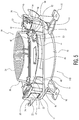
- FIG. 5 is a cross-sectional view of the low-profile niche of FIG. 1 with a light secured thereto;
- FIG. 7 is a semi-exploded, perspective view showing another embodiment of the low-profile niche of the present disclosure, which includes a rotatable hub;
- FIG. 8 is a front view of the low-profile niche of FIG. 7 , showing the conduit hub of the niche mounted at the 12:00 position;
- the rear wall 20 includes a conduit aperture 26 that provides access to the angled conduit hub 18 mounted to the exterior of the rear wall 20 .
- the conduit aperture 26 allows for a power/control cable of a light to extend through the rear wall 20 and into the angled conduit hub 18 .
- the angled conduit hub 18 is generally provided at a 45° angle, and may be connected to a conduit pipe having a 45° bend. As such, the conduit of the light may bend a full 90° and run parallel to the face of the niche installation.
- the angled conduit hub 18 may be a separate piece that is attached/mounted to the exterior of the rear wall 20 , or, alternatively, may be a formed as a part of the body 12 extending from the rear wall 20 .
- the low profile side wall 22 along with the angled conduit hub 18 , allows the conduit to travel away from the niche 10 parallel to the plane of the rear wall 20 .
- a cord seal could be provided in the conduit hub 18 to prevent ingress of water through the hub 18 .
- the light mounting ribs 14 are mounted on the inner surface of the side wall 22 , and on the rear wall 20 .
- the mounting ribs 14 include a lateral groove 27 extending a predefined depth into the mounting ribs 14 and across each mounting rib 14 .
- the lateral grooves 27 allow a light to be mounted to the niche 10 , as discussed in greater detail below.
- the light 28 generally includes a front housing portion 30 and a rear housing portion 32 .
- the front housing portion 30 includes a lens 34 , an interlocking member 36 , and a radial flange or bezel 38 .
- the rear housing portion 32 includes a rear wall 40 and an interlocking member 42 .
- the interlocking member 36 of the front housing portion 30 interlocks with the interlocking member 42 of the rear wall 40 so that the front housing portion 30 and the rear housing portion 32 can be interconnected in a water-tight arrangement.
- a sealing material may be disposed between the interlocking members 36 , 42 so that the light 28 is sealed.
- the radial flange 38 extends radially from front housing 30 and is provided so that when the light 28 is placed in the niche 10 , it contacts a front face of the side wall 22 .
- the light 28 further includes a locking mechanism 44 attached to the exterior of the rear wall 40 of the rear housing 32 , and four locking tabs 45 extending radially from the rear wall 40 located at approximately equidistant positions along the circumference of the rear wall 40 .
- the locking mechanism 44 includes a body 46 , a bendable tab 48 , and a stopper 50 .
- the bendable tab 48 includes a flexure arm 52 and an engagement head 54 .
- the body 46 is secured to the rear wall 40 of the rear housing 32 .
- the light 28 may include a hole or slot 60 disposed in and extending through the radial flange 38 of the light 28 , to permit a pin or screwdriver to be inserted therein and to bend the flexure arm 52 radially inwardly so that the light 28 can be rotated counter-clockwise and the flexure arm 52 , and the locking tabs 45 , can be rotated out of the lateral grooves 27 without the flat face 56 of the engagement head 54 locking against the sidewall of the mounting rib 14 .
- a trim plate 61 (or, bezel) could be provided on the light 28 , to provide a pleasing aesthetic effect for the light.
- the plate 61 functions to cover the apertures 60 in the flange 38 , to prevent against undesired removal of the light 28 from the niche 10 .
- slots 63 are provided on the plate 61 to allow insertion of a tool (e.g., a flat-blades screwdriver) to remove the plate 61 , so that access can be gained to the apertures 60 , to allow removal of the light 28 .
- FIGS. 7-9 illustrate another embodiment of the low-profile niche, which includes a rotatable and adjustable hub.
- the low-profile niche 110 is similar in structure to the niche 10 of FIGS. 1-6 , with the exception that it does not include the mounting ribs 14 as internal structures to the niche. As such, the niche 110 functions nearly identical to the niche 10 of FIGS. 1-6 , except the light cannot mount directly to the niche 110 .
- the niche 110 includes a body 111 and a rotatable mounting hub 200 for mounting in the body 111 of the niche 110 .
- the mounting hub 200 includes a central portion 202 , four arms 204 disposed equidistantly about the central portion 202 , a rim 206 , and four light mounting ribs 208 .
- the arms 204 are spaced by openings 205 and include a rear wall portion 210 and a side wall portion 212 , wherein the rear wall portion 210 extends from the central portion 202 and the side wall portion 212 extends perpendicularly from the rear wall portion 210 to the rim 206 .
- the rotatable mounting hub 200 is generally sized to fit the niche body 111 such that, when inserted, the face of the rim 206 is approximately coplanar with the front face of the niche body 111 .
- the rotation guide 114 is viewable through either the first or second window 218 , 220 of the hub 200 , with the angle of the hub 200 being visible. Accordingly, a user may loosen the screw 224 so that the hub 200 can be rotated to a different angle, which may be determined by the user based upon the rotation guide 114 .
- the light 28 can be attached to the hub 200 in an identical fashion. As such, a user would first secure the hub 200 to the niche body 111 at a desired angle, and then insert the light 28 and rotate it clockwise to lock the light 28 to the mounting ribs 208 .
- the light conduit would extend through one of the openings 205 , through the conduit aperture 118 , into the angled conduit hub 120 , and to a controller.
- 7-9 allows a user to rotate the hub 200 counter-clockwise 10° to compensate for this “skew” of the body 111 .
- the user can secure the hub 200 to the niche body 111 at the compensated angle so that the light can be mounted with the “top” at the 12:00 position.
Abstract
Description
Claims (31)
Priority Applications (2)
| Application Number | Priority Date | Filing Date | Title |
|---|---|---|---|
| US14/727,030 US10941920B2 (en) | 2012-10-03 | 2015-06-01 | Low-profile niche for underwater pool/spa lights |
| US17/196,684 US11378257B2 (en) | 2012-10-03 | 2021-03-09 | Low-profile niche for underwater pool/spa lights |
Applications Claiming Priority (2)
| Application Number | Priority Date | Filing Date | Title |
|---|---|---|---|
| US13/573,708 US9046247B2 (en) | 2012-10-03 | 2012-10-03 | Low-profile niche for underwater pool/spa lights |
| US14/727,030 US10941920B2 (en) | 2012-10-03 | 2015-06-01 | Low-profile niche for underwater pool/spa lights |
Related Parent Applications (1)
| Application Number | Title | Priority Date | Filing Date |
|---|---|---|---|
| US13/573,708 Continuation US9046247B2 (en) | 2012-10-03 | 2012-10-03 | Low-profile niche for underwater pool/spa lights |
Related Child Applications (1)
| Application Number | Title | Priority Date | Filing Date |
|---|---|---|---|
| US17/196,684 Continuation US11378257B2 (en) | 2012-10-03 | 2021-03-09 | Low-profile niche for underwater pool/spa lights |
Publications (2)
| Publication Number | Publication Date |
|---|---|
| US20150260375A1 US20150260375A1 (en) | 2015-09-17 |
| US10941920B2 true US10941920B2 (en) | 2021-03-09 |
Family
ID=50385006
Family Applications (3)
| Application Number | Title | Priority Date | Filing Date |
|---|---|---|---|
| US13/573,708 Active US9046247B2 (en) | 2012-10-03 | 2012-10-03 | Low-profile niche for underwater pool/spa lights |
| US14/727,030 Active 2033-08-30 US10941920B2 (en) | 2012-10-03 | 2015-06-01 | Low-profile niche for underwater pool/spa lights |
| US17/196,684 Active US11378257B2 (en) | 2012-10-03 | 2021-03-09 | Low-profile niche for underwater pool/spa lights |
Family Applications Before (1)
| Application Number | Title | Priority Date | Filing Date |
|---|---|---|---|
| US13/573,708 Active US9046247B2 (en) | 2012-10-03 | 2012-10-03 | Low-profile niche for underwater pool/spa lights |
Family Applications After (1)
| Application Number | Title | Priority Date | Filing Date |
|---|---|---|---|
| US17/196,684 Active US11378257B2 (en) | 2012-10-03 | 2021-03-09 | Low-profile niche for underwater pool/spa lights |
Country Status (1)
| Country | Link |
|---|---|
| US (3) | US9046247B2 (en) |
Cited By (1)
| Publication number | Priority date | Publication date | Assignee | Title |
|---|---|---|---|---|
| US11378257B2 (en) | 2012-10-03 | 2022-07-05 | Hayward Industries, Inc. | Low-profile niche for underwater pool/spa lights |
Families Citing this family (12)
| Publication number | Priority date | Publication date | Assignee | Title |
|---|---|---|---|---|
| US9392711B2 (en) | 2012-10-03 | 2016-07-12 | Hayward Industries, Inc. | Electrical junction box with built-in isolation transformer |
| US10119685B2 (en) | 2014-12-03 | 2018-11-06 | CP IP Holdings Limited | Lighting arrangement |
| US9921364B2 (en) | 2015-01-03 | 2018-03-20 | CP IP Holdings Limited | Lighting arrangement |
| US10039161B2 (en) | 2014-12-03 | 2018-07-31 | CP IP Holdings Limited | Lighting arrangement with battery backup |
| US10168031B2 (en) | 2014-12-03 | 2019-01-01 | CP IP Holdings Limited | Lighting arrangement |
| US9845941B2 (en) | 2015-12-07 | 2017-12-19 | Kuzco Lighting | Lighting arrangement |
| USD784601S1 (en) | 2015-12-07 | 2017-04-18 | Kuzco Lighting | Lighting arrangement |
| USD791396S1 (en) | 2016-01-18 | 2017-07-04 | Kuzco Lighting | Lighting enclosure |
| US10072831B2 (en) | 2016-09-30 | 2018-09-11 | Intermatic Incorporated | Pool junction box with transformer |
| US10938245B1 (en) | 2018-07-06 | 2021-03-02 | Bellson Electric Pty Ltd | Universal resonant induction coupling for luminaire in a high-moisture environment |
| US10681793B1 (en) | 2019-08-16 | 2020-06-09 | Pal Lighting, Llc | Direct wireless control of lighting systems for use in a high-moisture environment |
| US11635192B1 (en) | 2021-12-27 | 2023-04-25 | Bellson Electric Pty Ltd | Adjustable underwater light fixture adapter |
Citations (43)
| Publication number | Priority date | Publication date | Assignee | Title |
|---|---|---|---|---|
| US1054747A (en) * | 1912-06-17 | 1913-03-04 | Badger Brass Mfg Company | Lamp. |
| US1678137A (en) * | 1927-07-02 | 1928-07-24 | Harry A Douglas | Casing having light-transmitting closure |
| US1711264A (en) * | 1926-06-23 | 1929-04-30 | Miller Co | Shade holder |
| US2518936A (en) * | 1945-12-07 | 1950-08-15 | Colonnade Company | Lighting fixture of the recessed ceiling type |
| US2781737A (en) | 1953-09-17 | 1957-02-19 | Bendix Aviat Corp | Illuminated dials |
| US4053758A (en) * | 1974-06-06 | 1977-10-11 | Swan Recreational Products Limited | Underwater swimming pool illumination systems |
| US4574337A (en) * | 1984-02-10 | 1986-03-04 | Gty Industries | Underwater lights |
| US4656689A (en) | 1986-04-01 | 1987-04-14 | Molded Products Company | Grommet |
| US4999757A (en) | 1989-08-15 | 1991-03-12 | Gty Industries | Niche mounted light fixture |
| US5075831A (en) * | 1991-02-07 | 1991-12-24 | Hubbell Incorporated | Lighting fixture assembly |
| US5349505A (en) * | 1992-11-24 | 1994-09-20 | Gty Industries | Wet niche light |
| US5394316A (en) * | 1993-04-12 | 1995-02-28 | Welch Allyn, Inc. | Locking lamp assembly for examination light |
| US5432688A (en) * | 1993-03-12 | 1995-07-11 | H-Tech, Inc. | Plastic niche and grounding assembly therefor |
| US5465199A (en) | 1994-08-19 | 1995-11-07 | Sea Gull Lighting | System for attaching trim to lamp housing |
| US5567041A (en) * | 1995-08-14 | 1996-10-22 | Slocum; Karl | Self supporting recessed ceiling fixture |
| US5607224A (en) | 1993-03-12 | 1997-03-04 | H-Tech, Inc. | Plastic niche and grounding assembly therefor |
| US5758958A (en) * | 1996-10-15 | 1998-06-02 | Chen; Chun-Liang | Fog signal lamp |
| US5836678A (en) * | 1996-07-26 | 1998-11-17 | Nsi Enterprises, Inc. | Universal type I.C./non-type I.C. recessed downlight housing can assembly and method for marking the can assembly |
| US6068384A (en) * | 1998-04-07 | 2000-05-30 | Nsi Enterprises, Inc. | Lighting system |
| US6152571A (en) | 1997-11-12 | 2000-11-28 | Sacopa, S.A. | Adjustable lamp |
| US6203173B1 (en) | 1998-10-14 | 2001-03-20 | Wet Enterprises, Inc. | Lighting assembly having above water and underwater operational capabilities |
| US6241361B1 (en) | 1995-11-03 | 2001-06-05 | Laurence E. Thrasher | Submersible light fixture |
| US6382818B1 (en) * | 1999-10-01 | 2002-05-07 | Koito Manufacturing Co., Ltd. | Lighting device for a vehicle |
| US6669351B1 (en) * | 1999-10-21 | 2003-12-30 | Cooper Industries, Inc. | Airport in-pavement lighting fixture |
| US6899445B2 (en) * | 2002-08-07 | 2005-05-31 | Hubbell Incorporated | Attachment for a reflector in a light assembly |
| US6940016B1 (en) | 2003-08-06 | 2005-09-06 | Desa Ip, Llc | Electrical rough-in box for low voltage transformer |
| US20050237746A1 (en) * | 2004-04-26 | 2005-10-27 | Yiu Newman L M | Surface and recess mountable lighting fixture |
| US20060002104A1 (en) * | 2004-06-30 | 2006-01-05 | Willis Vance E | Underwater LED light |
| US20060072323A1 (en) | 2002-12-10 | 2006-04-06 | Brian Poggi | Underwater pool light |
| US20060262462A1 (en) | 2003-05-03 | 2006-11-23 | Robert Barton | Concealed Safety Lighting and Alerting System |
| US20070058374A1 (en) * | 2005-05-23 | 2007-03-15 | Genlyte Thomas Group, Llc | Luminaire Reflector Having Attachment Ring |
| US20070147052A1 (en) * | 2005-12-23 | 2007-06-28 | Wyatt Michael D | Directional Canopy Luminaire |
| US7320536B2 (en) * | 2006-03-06 | 2008-01-22 | Juno Manufacturing, Inc. | Fire rated recessed lighting assembly |
| US20080112157A1 (en) | 2006-11-14 | 2008-05-15 | Boothe Brian J | Underwater pool light |
| US20080273330A1 (en) * | 2007-05-04 | 2008-11-06 | Tyson Glenn M | Led lighting system |
| US7705240B2 (en) | 2005-10-27 | 2010-04-27 | Pentair Water Pool And Spa, Inc. | Cord seal for swimming pool and spa light niches |
| US20100127637A1 (en) * | 2008-11-21 | 2010-05-27 | Journee Lighting, Inc. | Removable led light assembly for use in a light fixture assembly |
| US7947903B2 (en) | 2008-12-18 | 2011-05-24 | Hubbell Incorporated | Snap-on wall plate assembly |
| US20110222268A1 (en) * | 2010-03-12 | 2011-09-15 | Dennis Pearson | Wall Mounted Aisle, Step and Corridor Light System |
| US20120106149A1 (en) * | 2010-11-02 | 2012-05-03 | Fusion Pool Products Inc. | Underwater and landscape lighting system |
| US20120162999A1 (en) * | 2010-12-22 | 2012-06-28 | Koninklijke Philips Electronics N.V. | Recessed luminaire with trim retaining mechanism and method thereof |
| US20140092606A1 (en) | 2012-10-03 | 2014-04-03 | Hayward Industries, Inc. | Low-profile niche for underwater pool/spa lights |
| US20140090865A1 (en) | 2012-10-03 | 2014-04-03 | Hayward Industries, Inc. | Electrical junction box with built-in isolation transformer |
Family Cites Families (1)
| Publication number | Priority date | Publication date | Assignee | Title |
|---|---|---|---|---|
| US8403513B2 (en) * | 2011-08-09 | 2013-03-26 | Custom Molded Products, Inc. | Pool light adapter ring |
-
2012
- 2012-10-03 US US13/573,708 patent/US9046247B2/en active Active
-
2015
- 2015-06-01 US US14/727,030 patent/US10941920B2/en active Active
-
2021
- 2021-03-09 US US17/196,684 patent/US11378257B2/en active Active
Patent Citations (44)
| Publication number | Priority date | Publication date | Assignee | Title |
|---|---|---|---|---|
| US1054747A (en) * | 1912-06-17 | 1913-03-04 | Badger Brass Mfg Company | Lamp. |
| US1711264A (en) * | 1926-06-23 | 1929-04-30 | Miller Co | Shade holder |
| US1678137A (en) * | 1927-07-02 | 1928-07-24 | Harry A Douglas | Casing having light-transmitting closure |
| US2518936A (en) * | 1945-12-07 | 1950-08-15 | Colonnade Company | Lighting fixture of the recessed ceiling type |
| US2781737A (en) | 1953-09-17 | 1957-02-19 | Bendix Aviat Corp | Illuminated dials |
| US4053758A (en) * | 1974-06-06 | 1977-10-11 | Swan Recreational Products Limited | Underwater swimming pool illumination systems |
| US4574337A (en) * | 1984-02-10 | 1986-03-04 | Gty Industries | Underwater lights |
| US4656689A (en) | 1986-04-01 | 1987-04-14 | Molded Products Company | Grommet |
| US4999757A (en) | 1989-08-15 | 1991-03-12 | Gty Industries | Niche mounted light fixture |
| US5075831A (en) * | 1991-02-07 | 1991-12-24 | Hubbell Incorporated | Lighting fixture assembly |
| US5349505A (en) * | 1992-11-24 | 1994-09-20 | Gty Industries | Wet niche light |
| US5556188A (en) | 1992-11-24 | 1996-09-17 | Gty Industries | Wet niche light |
| US5432688A (en) * | 1993-03-12 | 1995-07-11 | H-Tech, Inc. | Plastic niche and grounding assembly therefor |
| US5607224A (en) | 1993-03-12 | 1997-03-04 | H-Tech, Inc. | Plastic niche and grounding assembly therefor |
| US5394316A (en) * | 1993-04-12 | 1995-02-28 | Welch Allyn, Inc. | Locking lamp assembly for examination light |
| US5465199A (en) | 1994-08-19 | 1995-11-07 | Sea Gull Lighting | System for attaching trim to lamp housing |
| US5567041A (en) * | 1995-08-14 | 1996-10-22 | Slocum; Karl | Self supporting recessed ceiling fixture |
| US6241361B1 (en) | 1995-11-03 | 2001-06-05 | Laurence E. Thrasher | Submersible light fixture |
| US5836678A (en) * | 1996-07-26 | 1998-11-17 | Nsi Enterprises, Inc. | Universal type I.C./non-type I.C. recessed downlight housing can assembly and method for marking the can assembly |
| US5758958A (en) * | 1996-10-15 | 1998-06-02 | Chen; Chun-Liang | Fog signal lamp |
| US6152571A (en) | 1997-11-12 | 2000-11-28 | Sacopa, S.A. | Adjustable lamp |
| US6068384A (en) * | 1998-04-07 | 2000-05-30 | Nsi Enterprises, Inc. | Lighting system |
| US6203173B1 (en) | 1998-10-14 | 2001-03-20 | Wet Enterprises, Inc. | Lighting assembly having above water and underwater operational capabilities |
| US6382818B1 (en) * | 1999-10-01 | 2002-05-07 | Koito Manufacturing Co., Ltd. | Lighting device for a vehicle |
| US6669351B1 (en) * | 1999-10-21 | 2003-12-30 | Cooper Industries, Inc. | Airport in-pavement lighting fixture |
| US6899445B2 (en) * | 2002-08-07 | 2005-05-31 | Hubbell Incorporated | Attachment for a reflector in a light assembly |
| US20060072323A1 (en) | 2002-12-10 | 2006-04-06 | Brian Poggi | Underwater pool light |
| US20060262462A1 (en) | 2003-05-03 | 2006-11-23 | Robert Barton | Concealed Safety Lighting and Alerting System |
| US6940016B1 (en) | 2003-08-06 | 2005-09-06 | Desa Ip, Llc | Electrical rough-in box for low voltage transformer |
| US20050237746A1 (en) * | 2004-04-26 | 2005-10-27 | Yiu Newman L M | Surface and recess mountable lighting fixture |
| US20060002104A1 (en) * | 2004-06-30 | 2006-01-05 | Willis Vance E | Underwater LED light |
| US20070058374A1 (en) * | 2005-05-23 | 2007-03-15 | Genlyte Thomas Group, Llc | Luminaire Reflector Having Attachment Ring |
| US7705240B2 (en) | 2005-10-27 | 2010-04-27 | Pentair Water Pool And Spa, Inc. | Cord seal for swimming pool and spa light niches |
| US20070147052A1 (en) * | 2005-12-23 | 2007-06-28 | Wyatt Michael D | Directional Canopy Luminaire |
| US7320536B2 (en) * | 2006-03-06 | 2008-01-22 | Juno Manufacturing, Inc. | Fire rated recessed lighting assembly |
| US20080112157A1 (en) | 2006-11-14 | 2008-05-15 | Boothe Brian J | Underwater pool light |
| US20080273330A1 (en) * | 2007-05-04 | 2008-11-06 | Tyson Glenn M | Led lighting system |
| US20100127637A1 (en) * | 2008-11-21 | 2010-05-27 | Journee Lighting, Inc. | Removable led light assembly for use in a light fixture assembly |
| US7947903B2 (en) | 2008-12-18 | 2011-05-24 | Hubbell Incorporated | Snap-on wall plate assembly |
| US20110222268A1 (en) * | 2010-03-12 | 2011-09-15 | Dennis Pearson | Wall Mounted Aisle, Step and Corridor Light System |
| US20120106149A1 (en) * | 2010-11-02 | 2012-05-03 | Fusion Pool Products Inc. | Underwater and landscape lighting system |
| US20120162999A1 (en) * | 2010-12-22 | 2012-06-28 | Koninklijke Philips Electronics N.V. | Recessed luminaire with trim retaining mechanism and method thereof |
| US20140092606A1 (en) | 2012-10-03 | 2014-04-03 | Hayward Industries, Inc. | Low-profile niche for underwater pool/spa lights |
| US20140090865A1 (en) | 2012-10-03 | 2014-04-03 | Hayward Industries, Inc. | Electrical junction box with built-in isolation transformer |
Non-Patent Citations (5)
| Title |
|---|
| Notice of Allowance dated Jan. 28, 2015 from U.S. Appl. No. 13/573,708 (8 pages). |
| Office Action dated May 15, 2014, issued in connection with U.S. Appl. No. 13/573,694 (12 pages). |
| Office Action dated May 8, 2014 from U.S. Appl. No. 13/573,708 (25 pages). |
| Pentair GLOBRITE Color Changing LED Pool/Spa Light Installation and User's Guide, Sep. 2012 (25 pages). |
| PowerPoint Presentation entitled "Lighting," dated Oct. 3, 2011 (15 pages). |
Cited By (1)
| Publication number | Priority date | Publication date | Assignee | Title |
|---|---|---|---|---|
| US11378257B2 (en) | 2012-10-03 | 2022-07-05 | Hayward Industries, Inc. | Low-profile niche for underwater pool/spa lights |
Also Published As
| Publication number | Publication date |
|---|---|
| US11378257B2 (en) | 2022-07-05 |
| US20140092606A1 (en) | 2014-04-03 |
| US9046247B2 (en) | 2015-06-02 |
| US20210190297A1 (en) | 2021-06-24 |
| US20150260375A1 (en) | 2015-09-17 |
Similar Documents
| Publication | Publication Date | Title |
|---|---|---|
| US11378257B2 (en) | Low-profile niche for underwater pool/spa lights | |
| US7105742B1 (en) | Electrical box with mounting screw guide | |
| US7435900B1 (en) | Recessed electrical box | |
| US8148635B1 (en) | Camera mounting assembly including mounting bar and adapter plate for mounting a security camera or fixture to an electrical box | |
| US7897870B1 (en) | Cable routing assembly including low voltage bracket and scoop | |
| US8158884B2 (en) | Angled slots for installation of outdoor metallic boxes | |
| US7757875B2 (en) | Pull out extension contained in electrical box | |
| US6239368B1 (en) | Siding box | |
| US7246929B2 (en) | Landscape lightpost with receptacle cavity | |
| US6241368B1 (en) | Electrical light fixture assembly | |
| US6774304B1 (en) | Siding box assembly | |
| US8748744B2 (en) | Electrical box extender assembly | |
| US8076575B1 (en) | Electrical box assembly for mounting and supporting a security camera or fixture | |
| CN111201686B (en) | Weatherproof electrical enclosure with reinforcement | |
| RU2681088C2 (en) | Electrical device with secure connection | |
| EP3654474B1 (en) | Electrical installation box assembly | |
| US9101051B1 (en) | Flush mounting utility component assembly | |
| US11199313B2 (en) | Fastening system for flush mounting a device and flush-mountable device | |
| CA3123901A1 (en) | Round adjustable mud ring assembly | |
| US11641096B2 (en) | Electrical box cable management and support bracket assembly, system and method | |
| US20160141852A1 (en) | Self-aligning box and sleeve assembly | |
| US8324516B1 (en) | Rapid mount electrical cable entry device with flexible slotted insert | |
| EP3951492A1 (en) | Universal mounting case for video cameras | |
| NZ570544A (en) | Mounting box for electrical wiring accessories and assemblies and installations including such mounting box | |
| US9748751B1 (en) | Electrical box assembly for angled recessed mounting of high and low voltage components |
Legal Events
| Date | Code | Title | Description |
|---|---|---|---|
| AS | Assignment |
Owner name: HAYWARD INDUSTRIES, INC., NEW JERSEY Free format text: ASSIGNMENT OF ASSIGNORS INTEREST;ASSIGNORS:POTUCEK, KEVIN;DAVIDSON, CARL;LEVIN, ALAN;AND OTHERS;SIGNING DATES FROM 20131107 TO 20131119;REEL/FRAME:035755/0446 |
|
| AS | Assignment |
Owner name: BANK OF AMERICA, N.A., AS COLLATERAL AGENT, ILLINOIS Free format text: FIRST LIEN PATENT SECURITY AGREEMENT;ASSIGNOR:HAYWARD INDUSTRIES, INC.;REEL/FRAME:043796/0407 Effective date: 20170804 Owner name: BANK OF AMERICA, N.A., AS COLLATERAL AGENT, ILLINO Free format text: FIRST LIEN PATENT SECURITY AGREEMENT;ASSIGNOR:HAYWARD INDUSTRIES, INC.;REEL/FRAME:043796/0407 Effective date: 20170804 |
|
| AS | Assignment |
Owner name: BANK OF AMERICA, N.A., AS COLLATERAL AGENT, ILLINOIS Free format text: SECOND LIEN PATENT SECURITY AGREEMENT;ASSIGNOR:HAYWARD INDUSTRIES, INC.;REEL/FRAME:043790/0558 Effective date: 20170804 Owner name: BANK OF AMERICA, N.A., AS COLLATERAL AGENT, ILLINO Free format text: SECOND LIEN PATENT SECURITY AGREEMENT;ASSIGNOR:HAYWARD INDUSTRIES, INC.;REEL/FRAME:043790/0558 Effective date: 20170804 |
|
| AS | Assignment |
Owner name: BANK OF AMERICA, N.A., AS COLLATERAL AGENT, PENNSYLVANIA Free format text: SECURITY INTEREST;ASSIGNOR:HAYWARD INDUSTRIES, INC.;REEL/FRAME:043812/0694 Effective date: 20170804 Owner name: BANK OF AMERICA, N.A., AS COLLATERAL AGENT, PENNSY Free format text: SECURITY INTEREST;ASSIGNOR:HAYWARD INDUSTRIES, INC.;REEL/FRAME:043812/0694 Effective date: 20170804 |
|
| STPP | Information on status: patent application and granting procedure in general |
Free format text: FINAL REJECTION MAILED |
|
| STPP | Information on status: patent application and granting procedure in general |
Free format text: DOCKETED NEW CASE - READY FOR EXAMINATION |
|
| STPP | Information on status: patent application and granting procedure in general |
Free format text: NON FINAL ACTION MAILED |
|
| STPP | Information on status: patent application and granting procedure in general |
Free format text: FINAL REJECTION MAILED |
|
| STPP | Information on status: patent application and granting procedure in general |
Free format text: RESPONSE TO NON-FINAL OFFICE ACTION ENTERED AND FORWARDED TO EXAMINER |
|
| AS | Assignment |
Owner name: HAYWARD INDUSTRIES, INC., NEW JERSEY Free format text: ASSIGNEE CHANGE OF ADDRESS;ASSIGNOR:HAYWARD INDUSTRIES, INC.;REEL/FRAME:055137/0235 Effective date: 20200116 |
|
| STCF | Information on status: patent grant |
Free format text: PATENTED CASE |
|
| AS | Assignment |
Owner name: HAYWARD INDUSTRIES, INC., NEW JERSEY Free format text: RELEASE OF PATENT SECURITY INTEREST (SECOND LIEN);ASSIGNOR:BANK OF AMERICA, N.A., AS COLLATERAL AGENT;REEL/FRAME:056122/0218 Effective date: 20210319 Owner name: GSG HOLDINGS, INC., ARIZONA Free format text: RELEASE OF PATENT SECURITY INTEREST (SECOND LIEN);ASSIGNOR:BANK OF AMERICA, N.A., AS COLLATERAL AGENT;REEL/FRAME:056122/0218 Effective date: 20210319 |