US10932489B2 - Nicotine delivery system - Google Patents
Nicotine delivery system Download PDFInfo
- Publication number
- US10932489B2 US10932489B2 US15/032,364 US201415032364A US10932489B2 US 10932489 B2 US10932489 B2 US 10932489B2 US 201415032364 A US201415032364 A US 201415032364A US 10932489 B2 US10932489 B2 US 10932489B2
- Authority
- US
- United States
- Prior art keywords
- actuator
- chamber
- actuation
- delivery system
- nicotine delivery
- Prior art date
- Legal status (The legal status is an assumption and is not a legal conclusion. Google has not performed a legal analysis and makes no representation as to the accuracy of the status listed.)
- Active, expires
Links
Images


Classifications
-
- A—HUMAN NECESSITIES
- A61—MEDICAL OR VETERINARY SCIENCE; HYGIENE
- A61M—DEVICES FOR INTRODUCING MEDIA INTO, OR ONTO, THE BODY; DEVICES FOR TRANSDUCING BODY MEDIA OR FOR TAKING MEDIA FROM THE BODY; DEVICES FOR PRODUCING OR ENDING SLEEP OR STUPOR
- A61M11/00—Sprayers or atomisers specially adapted for therapeutic purposes
- A61M11/006—Sprayers or atomisers specially adapted for therapeutic purposes operated by applying mechanical pressure to the liquid to be sprayed or atomised
- A61M11/007—Syringe-type or piston-type sprayers or atomisers
-
- A—HUMAN NECESSITIES
- A61—MEDICAL OR VETERINARY SCIENCE; HYGIENE
- A61M—DEVICES FOR INTRODUCING MEDIA INTO, OR ONTO, THE BODY; DEVICES FOR TRANSDUCING BODY MEDIA OR FOR TAKING MEDIA FROM THE BODY; DEVICES FOR PRODUCING OR ENDING SLEEP OR STUPOR
- A61M16/00—Devices for influencing the respiratory system of patients by gas treatment, e.g. ventilators; Tracheal tubes
- A61M16/20—Valves specially adapted to medical respiratory devices
-
- A—HUMAN NECESSITIES
- A24—TOBACCO; CIGARS; CIGARETTES; SIMULATED SMOKING DEVICES; SMOKERS' REQUISITES
- A24F—SMOKERS' REQUISITES; MATCH BOXES; SIMULATED SMOKING DEVICES
- A24F40/00—Electrically operated smoking devices; Component parts thereof; Manufacture thereof; Maintenance or testing thereof; Charging means specially adapted therefor
- A24F40/40—Constructional details, e.g. connection of cartridges and battery parts
- A24F40/42—Cartridges or containers for inhalable precursors
-
- A—HUMAN NECESSITIES
- A24—TOBACCO; CIGARS; CIGARETTES; SIMULATED SMOKING DEVICES; SMOKERS' REQUISITES
- A24F—SMOKERS' REQUISITES; MATCH BOXES; SIMULATED SMOKING DEVICES
- A24F40/00—Electrically operated smoking devices; Component parts thereof; Manufacture thereof; Maintenance or testing thereof; Charging means specially adapted therefor
- A24F40/40—Constructional details, e.g. connection of cartridges and battery parts
- A24F40/48—Fluid transfer means, e.g. pumps
- A24F40/485—Valves; Apertures
-
- A—HUMAN NECESSITIES
- A24—TOBACCO; CIGARS; CIGARETTES; SIMULATED SMOKING DEVICES; SMOKERS' REQUISITES
- A24F—SMOKERS' REQUISITES; MATCH BOXES; SIMULATED SMOKING DEVICES
- A24F42/00—Simulated smoking devices other than electrically operated; Component parts thereof; Manufacture or testing thereof
- A24F42/20—Devices without heating means
-
- A—HUMAN NECESSITIES
- A24—TOBACCO; CIGARS; CIGARETTES; SIMULATED SMOKING DEVICES; SMOKERS' REQUISITES
- A24F—SMOKERS' REQUISITES; MATCH BOXES; SIMULATED SMOKING DEVICES
- A24F42/00—Simulated smoking devices other than electrically operated; Component parts thereof; Manufacture or testing thereof
- A24F42/60—Constructional details
-
- A24F47/002—
-
- A—HUMAN NECESSITIES
- A61—MEDICAL OR VETERINARY SCIENCE; HYGIENE
- A61M—DEVICES FOR INTRODUCING MEDIA INTO, OR ONTO, THE BODY; DEVICES FOR TRANSDUCING BODY MEDIA OR FOR TAKING MEDIA FROM THE BODY; DEVICES FOR PRODUCING OR ENDING SLEEP OR STUPOR
- A61M15/00—Inhalators
- A61M15/06—Inhaling appliances shaped like cigars, cigarettes or pipes
-
- A—HUMAN NECESSITIES
- A61—MEDICAL OR VETERINARY SCIENCE; HYGIENE
- A61M—DEVICES FOR INTRODUCING MEDIA INTO, OR ONTO, THE BODY; DEVICES FOR TRANSDUCING BODY MEDIA OR FOR TAKING MEDIA FROM THE BODY; DEVICES FOR PRODUCING OR ENDING SLEEP OR STUPOR
- A61M16/00—Devices for influencing the respiratory system of patients by gas treatment, e.g. ventilators; Tracheal tubes
- A61M16/20—Valves specially adapted to medical respiratory devices
- A61M16/208—Non-controlled one-way valves, e.g. exhalation, check, pop-off non-rebreathing valves
- A61M16/209—Relief valves
-
- B65D83/0033—
-
- B—PERFORMING OPERATIONS; TRANSPORTING
- B65—CONVEYING; PACKING; STORING; HANDLING THIN OR FILAMENTARY MATERIAL
- B65D—CONTAINERS FOR STORAGE OR TRANSPORT OF ARTICLES OR MATERIALS, e.g. BAGS, BARRELS, BOTTLES, BOXES, CANS, CARTONS, CRATES, DRUMS, JARS, TANKS, HOPPERS, FORWARDING CONTAINERS; ACCESSORIES, CLOSURES, OR FITTINGS THEREFOR; PACKAGING ELEMENTS; PACKAGES
- B65D83/00—Containers or packages with special means for dispensing contents
- B65D83/76—Containers or packages with special means for dispensing contents for dispensing fluent contents by means of a piston
- B65D83/765—Containers or packages with special means for dispensing contents for dispensing fluent contents by means of a piston the piston being a follower-piston and the dispensing means comprising a hand-operated pressure device at the opposite part of the container
Definitions
- the disclosure relates to a nicotine delivery system for administering a substance or formulation.
- Nicotine delivery systems comprise a mouthpiece, an actuator and a compartment containing a formulation. Upon actuation of the actuator by a user, formulation is released from the compartment and is expelled through the mouthpiece.
- a nicotine delivery system comprising a housing that has a longitudinal axis and which defines a chamber that is configured to receive a plunger and has an outlet for the passage of a formulation out of the chamber, and an actuating mechanism comprising an actuator and an actuation member, wherein the actuator cooperates with the actuation member such that when a plunger is received in the chamber the plunger and the chamber slide relative to each other in an axial direction by a predetermined incremental distance in response to each operation of the actuator by a user to displace a predetermined volume of formulation from the chamber through said outlet.
- the actuator may be moveable in a direction transverse to the axial direction to cause the plunger and the chamber to slide relative to each other.
- the actuator is mounted to the housing and comprises a button that is depressible inwardly towards the axis to displace the actuation member.
- the actuator is slidably received in an aperture in the housing.
- the actuator may be pivotally mounted to the housing.
- the actuator comprises a diaphragm that is deformable in a direction transverse the axial direction.
- the diaphragm partitions the inside of the housing into first and second compartments and wherein the actuation member is disposed in the first compartment, and wherein one of the first and second compartments comprises a suction channel and the user applies suction to the suction channel to deform the diaphragm in a direction transverse the axial direction.
- the other of the first and second compartments may be hermetically sealed.
- the housing may comprise a ventilation aperture that fluidly communicates the other of the first and second compartments with the atmosphere.
- the nicotine delivery system may comprise a first biasing means that is configured to bias the actuation member in an axial direction.
- the nicotine delivery system may comprise a protrusion and a first cam track, wherein in a first position the protrusion is urged against a first stopper surface of a plurality of stopper surfaces of the first cam track to prevent displacement of the actuation member in the direction of the force of the first biasing means.
- the protrusion may be moveable to a second position in response to actuation of the actuator by the user wherein the protrusion is urged away from the first stopper surface so that the first biasing means displaces the first cam track relative to the protrusion until the protrusion is urged against a second stopper surface of the first cam track.
- one of the actuator and actuation member comprises the protrusion and the other of the actuator and actuation member comprises the first cam track and wherein the actuator is moveable relative to the actuation member to displace the first cam track relative to the protrusion.
- the first cam track may comprise a plurality of guide channels that are angled with respect to the axial direction and are sequentially arranged in the axial direction to form a zigzag shaped cut-out.
- One of each of the plurality of stopper surfaces may be disposed at a first end of each of the plurality of guide channels.
- the actuation member comprises one of the protrusion and first cam track and the other of the protrusion and first cam track is held in a fixed position relative to the housing, and wherein the actuator is configured to rotate the actuation member relative to the protrusion to urge the protrusion away from the first stopper surface.
- the first cam track may comprise a plurality of guide channels that each extends in the axial direction and are arranged in a stepped formation. One of each of the plurality of stopper surfaces may be disposed at a first end of each of the plurality of guide channels.
- the actuation member may comprise an actuation surface and wherein the actuator comprises a projection that is configured to be urged against the actuation surface to rotate the actuation member in response to actuation of the actuator by the user.
- the actuation member comprises a second cam track having a plurality of second guide channels that each extends in an axial direction and are arranged in a stepped formation, and wherein each second guide channel comprises a surface facing in a direction transverse the axial direction that comprises an actuation surface.
- the actuation member may comprise a plurality of ratchet teeth, and wherein each ratchet tooth comprises an actuation surface.
- the actuator may be configured such that force exerted on the actuator upon actuation by the user is translated into a force that urges the actuation member in an axial direction.
- one of the actuator and actuation member comprises a protrusion and the other of the actuator and actuation member comprises a cam track that is configured to translate displacement of the actuator in a direction transverse an axial direction into displacement of the actuation member in an axial direction.
- the cam track may comprise a guide channel that is angled with respect to the axial direction and is configured to receive the protrusion.
- the guide channel may be formed between first and second guide members, a flexible member and a receiving member of the cam track.
- the flexible member may comprise a sloping portion that protrudes from a surface of the cam track and has a guide surface at an end thereof that is angled with respect to the axial direction and is configured so that when the actuator is urged towards the actuation member in response to actuation by the user the protrusion is urged against the angled guide surface and is displaced relative to the cam track at an angle to the axial direction.
- the protrusion may be urged against the sloped portion of the flexible member when the actuator is urged away from the actuation member so that the flexible member flexes to facilitate movement of the protrusion relative to the cam track in a direction transverse the axial direction.
- the actuation member comprises a plurality of ratchet teeth and the actuator comprises an arm and a lever that is pivotally mounted to the arm and is configured so that when the arm is urged in a direction transverse the axial direction in response to actuation by the user an end of the lever arm is urged against one of the ratchet teeth to urge the actuation member in an axial direction.
- Each ratchet tooth may comprise a connecting surface that extends between adjacent ratchet teeth and an actuation surface that faces in an axial direction, and wherein said end of the lever arm is urged against the actuation surface upon actuation of the actuator by the user.
- the arm may be integrally formed with the housing.
- the arm may comprise a resilient material.
- the chamber is integrally formed with the housing.
- the chamber comprises a canister that is removably received in the housing.
- the canister may comprise a plunger.
- the actuation member is configured to exert a force on the canister to slide the plunger relative to the chamber upon actuation of the actuator by the user.
- the nicotine delivery system may comprise a barrel that defines the chamber for formulation.
- the barrel comprises a canister that is received in the housing.
- the barrel is integrally formed with the housing.
- the actuation member is configured to exert a force on the plunger to slide the plunger relative to the chamber upon actuation of the actuator by the user. In an alternate embodiment, the actuation member is configured to exert a force on the barrel to slide the plunger relative to the barrel upon actuation of the actuator by the user.
- the nicotine delivery system comprises a mouthpiece with an outlet channel that may be fluidly communicated with the chamber of the housing to expel formulation therefrom.
- the nicotine delivery system may comprise a pressure relief valve that opens to fluidly communicate the housing chamber with the outlet channel when the pressure in the chamber reaches a pressure set-point, the nicotine delivery system being configured so that the pressure set-point is reached when the plunger is slid relative to the chamber upon actuation of the actuator by the user.
- the actuation member is urged away from the mouthpiece in the axial direction upon actuation of the actuator by the user.
- a bore may be disposed in the actuation member that is configured to fluidly communicate the chamber with an outlet of the nicotine delivery system.
- a seal may be provided between a peripheral wall of the actuation member and the inside of the housing.
- the actuation member is urged towards the mouthpiece in the axial direction upon actuation of the actuator by the user.
- the nicotine delivery system may comprise a biasing member that is configured to bias the actuator relative to the housing in a direction transverse the axial direction.
- a piston may be disposed on an end of the plunger and is slidably received in the chamber.
- the nicotine delivery system comprises the formulation in the chamber.
- the formulation may contain nicotine.
- the formulation may comprise tobacco and/or one or more flavors or flavorants.
- the formulation may be in an aqueous form or may be in a non-aqueous form, such as a powder form or a non-aqueous liquid form.
- Embodiments also provide a nicotine delivery system comprising a housing that has a longitudinal axis and which defines a chamber that is configured to receive a plunger and has an outlet for the passage of formulation out of the chamber, an actuation member that is configured such that when a plunger is received in the chamber the actuation member slides the plunger in an axial direction into the chamber to displace formulation from the outlet in response to rotation of the actuation member relative to the housing, a first biasing means configured to rotatably bias the actuation member, and an actuator to hold the actuation member against the bias until actuation of the actuator by a user.
- the nicotine delivery system may comprise a screw thread that is configured to translate rotation of the actuation member in a rotational direction into displacement of the actuation member in an axial direction.
- the nicotine delivery system comprises a mating portion that is held in a fixed position relative to the axial direction, and wherein the screw thread is disposed on the actuation member and is configured to cooperate with the mating portion.
- the nicotine delivery system comprises a mating portion that is disposed on the actuation member, and wherein the screw thread is held in a fixed position relative to the axial direction and is configured to cooperate with the mating portion.
- the mating portion comprises a second screw thread.
- the mating portion comprises a protrusion.
- the first biasing means may comprise a torsion spring.
- the actuator may comprise a first friction component that is configured to engage with a second friction component that is mounted to the actuation member to prevent the actuation member from rotating, the first friction component being urged away from the second friction component upon actuation of the actuator by the user to enable rotation of the actuation member.
- the nicotine delivery system may comprise a damper that is configured to damp the motion of the first biasing means.
- the chamber is integrally formed with the housing.
- the chamber comprises a canister that is removably received in the housing.
- the canister may comprise a plunger.
- the actuation member is configured to exert a force on the canister to slide the plunger relative to the chamber upon actuation of the actuator by the user.
- the actuation member is configured to exert a force on the plunger to slide the plunger relative to the chamber upon actuation of the actuator by the user.
- the nicotine delivery system comprises a mouthpiece with an outlet channel that may be fluidly communicated with the chamber of the housing to expel formulation therefrom.
- the nicotine delivery system may comprise a pressure relief valve that opens to fluidly communicate the housing chamber with the outlet channel when the pressure in the chamber reaches a pressure set-point, the nicotine delivery system being configured so that the pressure set-point is reached when the plunger is slid relative to the chamber upon actuation of the actuator by the user.
- the nicotine delivery system may comprise a biasing member that is configured to bias the actuator relative to the housing in a direction transverse the axial direction.
- the nicotine delivery system comprises the formulation in the chamber.
- the formulation may contain nicotine.
- the formulation may comprise tobacco and/or one or more flavors or flavorants.
- the formulation may be in an aqueous form or may be in a non-aqueous form, such as a powder form or a non-aqueous liquid form.
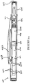
- FIG. 1 is a perspective view of a nicotine delivery system according to a first embodiment.
- FIG. 2 is a perspective view of part of the nicotine delivery system of FIG. 1 .
- FIG. 3 is a cross-sectional side view of the nicotine delivery system of FIG. 1 .
- FIG. 4 is a second cross-sectional side view of the nicotine delivery system of FIG. 1 .
- FIG. 5 is a perspective view of an actuator of the nicotine delivery system of FIG. 1 .
- FIG. 6 is a cross-sectional perspective view of the actuator of FIG. 5 .
- FIG. 7 is a side view of the actuator and an actuation rod of the nicotine delivery system of FIG. 1 , in a first position.
- FIG. 8 is a side view of the actuator and actuation rod of FIG. 7 , in a second position.
- FIG. 9 is a cross-sectional perspective view of the actuator and actuation rod of FIG. 7 , in the first position.
- FIG. 10 is a cross-sectional perspective view of the actuator and actuation rod of FIG. 7 , in the second position.
- FIG. 11 is a cross-sectional side view of a portion of the nicotine delivery system of FIG. 1 , in a retracted position.
- FIG. 12 is a cross-sectional side view of a portion of the nicotine delivery system of FIG. 1 , in an extended position.
- FIG. 13 is a perspective view of a nicotine delivery system according to a second embodiment.
- FIG. 14 is a perspective view of part of the nicotine delivery system of FIG. 13 .
- FIG. 15 is a cross-sectional side view of the nicotine delivery system of FIG. 13 .
- FIG. 16 is a cross-sectional side view of the nicotine delivery system of FIG. 13 .
- FIG. 17 is a cross-sectional side view of a portion of the nicotine delivery system of FIG. 13 , in a first position.
- FIG. 18 is a cross-sectional side view of a portion of the nicotine delivery system of FIG. 13 , in a second position.
- FIG. 19 is a perspective view of a nicotine delivery system of a third embodiment.
- FIG. 20 is a side view of the nicotine delivery system of FIG. 19 .
- FIG. 21 is a cross-sectional side view of the nicotine delivery system of FIG. 19 , in a first position.
- FIG. 22 is a cross-sectional side view of the nicotine delivery system of FIG. 19 , in a second position.
- FIG. 23 is a perspective view of a nicotine delivery system of a fourth embodiment.
- FIG. 24 is a perspective view of part of the nicotine delivery system of FIG. 23 .
- FIG. 25 is a perspective view of an actuator of the nicotine delivery system of FIG. 23 .
- FIG. 26 is a perspective view of an actuation rod of the nicotine delivery system of FIG. 23 .
- FIG. 27 is a cross-sectional side view of the nicotine delivery system of FIG. 23 .
- FIG. 28 is a side view of the actuator and actuation rod of FIG. 23 , in a first position.
- FIG. 29 is a side view of the actuator and actuation rod of FIG. 23 , in a second position.
- FIG. 30 is a side view of the actuator and actuation rod of FIG. 23 , in a third position.
- FIG. 31 is a perspective view of a nicotine delivery system of a fifth embodiment.
- FIG. 32 is a side view of the nicotine delivery system of FIG. 31 .
- FIG. 33 is a perspective view of an actuator of the nicotine delivery system of FIG. 31 .
- FIG. 34 is a perspective view of an actuation rod and biasing means of the nicotine delivery system of FIG. 31 .
- FIG. 35 is a cross-sectional side view of the nicotine delivery system of FIG. 31 .
- FIG. 36 is a side view of the actuator, biasing means and actuation rod of the nicotine delivery system of FIG. 31 , in a first position.
- FIG. 37 is a side view of the actuator, biasing means and actuation rod of the nicotine delivery system of FIG. 31 , in a second position.
- FIG. 38 is a perspective view of a nicotine delivery system of a sixth embodiment.
- FIG. 39 is a front view of the nicotine delivery system of FIG. 38 .
- FIG. 40 is a perspective view of an actuation rod of the nicotine delivery system of FIG. 38 .
- FIG. 41 is a perspective view of a diaphragm of the nicotine delivery system of FIG. 38 .
- FIG. 42 is a perspective view of the actuation rod and diaphragm of the nicotine delivery system of FIG. 38 .
- FIG. 43 is a front view of the actuation rod and diaphragm of the nicotine delivery system of FIG. 38 , in a first position.
- FIG. 44 is a front view of the actuation rod and diaphragm of the nicotine delivery system of FIG. 38 , in a second position.
- FIG. 45 is a front view of the actuation rod and diaphragm of the nicotine delivery system of FIG. 38 , in a third position.
- FIG. 46 is a cross-sectional side view of the nicotine delivery system of FIG. 38 .
- FIG. 47 is a perspective view of a nicotine delivery system of a seventh embodiment.
- FIG. 48 is a front view of the nicotine delivery system of FIG. 47 .
- FIG. 49 is a perspective view of the diaphragm of the nicotine delivery system of FIG. 47 .
- FIG. 50 is a perspective view of the diaphragm, an actuation rod and a friction wheel of the nicotine delivery system of FIG. 47 .
- FIG. 51 is a perspective view of part of the nicotine delivery system of FIG. 47 .
- FIG. 52 is a cross-sectional side view of the nicotine delivery system of FIG. 47 .
- FIG. 53 is a perspective view of a biasing means and a damper of the nicotine delivery system of FIG. 47 .
- the nicotine delivery system 1 may be used as a substitute for cigarette, cigar or like smoking article.
- the nicotine delivery system 1 comprises an outer housing 2 and an actuating mechanism 3 .
- the outer housing 2 comprises a cylindrical body 4 with a mouthpiece 5 at one end having an outlet channel 6 .
- An inner space 7 is formed in the cylindrical body 4 and has a chamber 8 B that contains a formulation.
- the chamber 8 B can be formed directly by the housing itself, the illustrated embodiments show that the chamber 8 B is formed from a separate, replaceable, canister 8 disposed in the body 4 .
- the canister 8 comprises a peripheral wall 8 A that encloses and defines the chamber 8 B.
- the chamber 8 B is sealed at one end by a plunger or piston 9 that is slidably received therein and the opposing end has an outlet 10 that is fluidly communicated with the outlet channel 6 .
- a pressure relief valve 11 is disposed between the outlet 10 and the outlet channel 6 and is configured to permit the flow of formulation from the chamber 8 B to the outlet channel 6 when the pressure of the formulation in the chamber 8 B reaches a pressure set-point.
- the pressure relief valve 11 comprises a valve ball 11 A, which is larger in diameter than the barrel outlet 10 , and a biasing means 11 B. When the pressure in the chamber 8 B is below the pressure set-point, the biasing means 11 B urges the valve ball 11 A into a position in which it seals the outlet 10 to prevent fluid from flowing from the chamber 8 B to the outlet channel 6 .
- the pressure relief valve 11 may be urged to an open position, wherein the valve ball 11 A is urged away from the outlet 10 so that a gap is formed that allows fluid to flow from the chamber 8 B to the outlet channel 6 , if the pressure in the chamber 8 B is increased so that it exerts a force on the valve ball 11 A that is sufficient to overcome the force of the biasing means 11 B.
- the actuating mechanism 3 comprises an actuation rod or member 12 and an actuator 13 .
- the actuation rod 12 is disposed in the outer housing 2 and is slidable in the longitudinal direction thereof.
- the actuation rod 12 comprises a longitudinal member 12 A with a first and second set of protrusions 12 B, 12 C arranged sequentially along the length of opposing sides of the longitudinal member 12 A.
- the actuator 13 comprises a main wall 14 with first and second side walls 15 A, 15 B co-extending from a major surface of the main wall 14 to form a generally U-shaped member.
- a button (not shown) is provided on a surface of the main wall 14 that is distal to the side walls 15 A, 15 B.
- the first and second side walls 15 A, 15 B each has an inner surface that faces towards the other of the first and second side walls 15 A, 15 B.
- the outer housing 2 comprises an aperture 2 A that is configured to slidably receive the actuator 13 so that the actuator 13 may be positioned so that the side walls 15 A, 15 b extend into the outer housing 2 on opposing sides of the actuation rod 12 .
- the first and second side walls 15 A, 15 B inner surfaces comprise first and second cam tracks 16 A, 16 B respectively.
- the first and second cam tracks 16 A, 16 B are identical and so only one will be described in detail hereinafter.
- the first cam track 16 A comprises a plurality of guide members 17 , receiving members 18 and flexible members 19 .
- the guide members 17 are arranged longitudinally along the inside surface of the first side wall 15 A towards an edge thereof that is distal to the main wall 14 .
- Each guide member 17 comprises a guide surface 17 A, that is angled to face towards the main wall 14 and away from the mouthpiece 5 when the actuator 3 is received in the outer housing 2 , and a stopper surface 17 B that is perpendicular to the main wall 14 and faces towards the mouthpiece 5 .
- the flexible members 19 are each integrally formed with the first side wall 15 A and comprise a free end that extends into a corresponding recess 19 A in the first side wall 15 A in a direction away from the main wall 14 .
- each flexible member 19 slopes towards the opposing second side wall 15 B to form a sloping portion 19 B that projects from the surface of the side wall 15 A and each free end comprises an angled guide surface 19 C that opposes the guide surface 17 A of a guide member 17 .
- the receiving members 18 are arranged longitudinally along the first side wall 15 A towards an edge thereof that is proximate to the main wall 14 .
- Each receiving member 18 comprises a guide surface 18 A that is co-planar to the guide surface 19 C of an adjacent flexible member 19 and a curved stopper surface 18 B that converges with an end of the guide surface 18 A that is proximate to the main wall 14 .
- a guide channel 20 is formed in each space between the guide surface 17 A of a guide member 17 , the guide surface 19 C of a flexible member 19 , the sloping portion 19 B of an adjacent flexible member 19 and the guide and stopper surfaces 18 A, 18 B of a receiving member 18 .
- the actuator 13 is slidable between a first position, wherein the actuator 13 protrudes out of the aperture 2 A in the outer housing 2 , and a second position, wherein the actuator 13 is slid further into the aperture 2 A in a direction transverse to the longitudinal axis of the cylindrical body 4 or to the direction in which the plunger 9 is movable relative to the chamber 8 B.
- the first set of protrusions 12 B engages with the first cam track 16 A and the second set of protrusions 12 C engages with the second cam track 16 B.
- the first and second cam tracks 16 A, 16 B are identical and the first and second sets of protrusions are identical 12 B, 12 C, and so only the engagement between the first cam track 16 A and the first set of protrusions 12 B will be described in detail.
- a first protrusion 12 B of the first set of protrusions 12 B abuts the stopper surface 17 B of a first guide member 17 (as shown in FIGS. 7 and 9 ). If a force is applied to the button of the actuator 13 by the user to push the actuator 13 into the second position, the main wall 14 will be urged towards the actuation rod 12 .
- a first flexible member 19 will prevent the first protrusion 12 B from moving directly towards the main wall 14 and so instead the first protrusion 12 B will move in a first guide channel 20 (in the direction shown by arrow ‘A’ in FIG. 9 ) until the protrusion 12 B abuts the curved stopper surface 18 B of a first receiving member 18 (as shown in FIGS. 8 and 10 ).
- the first protrusion 12 B moves within the first cam track 16 A at an angle to the direction that the actuator 13 is urged upon actuation by the user and so the force exerted on the actuator 13 in a direction transverse the longitudinal direction of the outer housing 2 is translated into a force that displaces the actuation rod 12 towards the mouthpiece 5 in the longitudinal direction.
- a biasing member (not shown), for example, a spring or portion of resilient material, is disposed between the actuator 13 and the outer housing 2 and biases the actuator 13 in a direction out of the aperture 2 A in the outer housing 2 . Therefore, when the user releases the button, the first protrusion 12 B is each urged away from the stopper surface 18 B of the first receiving member 18 and towards the sloping portion 19 B of a second flexible member 19 (in the direction shown by arrow ‘B’ in FIG. 10 ), which is adjacent the first flexible member 19 .
- a biasing member for example, a spring or portion of resilient material
- the flexible members 19 are manufactured from a material that has some resilience, for example, plastic, rubber or metal, and so the second flexible member 19 will flex within its aperture 19 A to sit flush to the inner surface of the side wall 15 A, so that the first protrusion 12 B can slide over the sloping portion 19 B and into a position wherein it lies adjacent to the stopper surface 17 B of a second guide member 17 , which is adjacent to the first guide member 17 .
- the second flexible member 19 will then return to its original position in which the sloping portion 19 B extends out of the inner surface of the side wall 15 A.
- the actuation rod 12 With the actuator 13 returned to its first position, the actuation rod 12 has been slid relative to the actuator 13 so that a second protrusion 12 B of the first set of protrusions 12 B, which is adjacent to the first protrusion 12 B, abuts the stopper surface 17 B of the first guide member 17 . If the user then presses and releases the button of the actuator 13 again, the second protrusion 12 B will move through the first guide channel 20 and then over the second flexible members 19 in the same manner as previously described with respect to the movement of the first protrusion 12 B.
- the remaining protrusions of the first set of protrusions 12 B may then be sequentially moved through the first guide channel 20 of the first cam track 16 A, in the manner described above, so that the actuation rod 12 is incrementally moveable relative to the actuator 13 upon actuation of the button.
- the actuation rod 12 abuts the piston 9 so that when the actuation rod 12 is moved incrementally upon actuation of the actuator 13 the piston 9 is slid within the chamber 8 B from a position wherein it is spaced from the outlet 10 (as shown in FIG. 11 ) to a position wherein it is urged nearer to the outlet 10 (as shown FIG. 12 ).
- the piston 9 moves towards the outlet 10 , the volume of the chamber 8 B decreases and so the pressure of the formulation in the chamber 8 B increases above the pressure set-point required to open the pressure relief valve 11 . Therefore, upon actuation of the actuator 13 , formulation flows from the outlet 10 , through the pressure relief valve 11 , and out of the mouthpiece outlet channel 6 .
- the nicotine delivery system 1 may be configured to release a safe dosage of formulation upon each actuation.
- the pressure in the chamber 8 B then reduces to below the pressure set-point and the pressure relief valve 11 closes.
- the actuator 13 may then again be actuated by the user to expel further doses of formulation from the mouthpiece 5 until the piston 9 has been slid in the chamber 8 B to a position wherein it lies proximate to the outlet 10 .
- the stopper surface 17 B of the first guide member 17 abuts against a protrusion of the first set of protrusions 12 B to prevent the actuation rod 12 , and thus the piston 9 , from being slid in a direction away from the mouthpiece 5 under the force of the pressure of formulation in the chamber 8 B.
- the pressure relief valve 11 comprises a valve ball 11 A that is urged towards the outlet 10 by a biasing means 11 B
- the pressure relief valve 11 may be of a different configuration.
- the pressure relief valve may comprise a static insert and a sliding insert.
- the sliding insert is slidably received in the outlet channel towards an end thereof that is spaced from the outlet.
- the sliding insert comprises an outlet aperture therethrough that, in use, vents to the inside of the user's mouth.
- the static insert comprises an insert passage and a face that is distal to the outlet.
- the static insert is disposed in the outlet channel between the outlet 10 and the sliding insert and the sliding insert is urged against the face of the static insert by a biasing means so that the aperture is blocked thereby.
- the pressure in the chamber 8 B reaches the pressure set-point, the pressure is sufficient to overcome the force of the biasing means so that the siding insert is urged away from the face of the static insert so that a gap is formed therebetween, allowing for formulation to flow from the chamber 8 B, through the valve outlet and then through the insert passage and out of the outlet aperture, via the gap formed between the static and sliding inserts.
- the pressure relief valve 11 is a separate component to the canister 8 and is positioned between the outlet 10 and the outlet channel 6 of the mouthpiece 5
- the pressure relief valve 11 is formed integrally with the canister 8 and is disposed in the outlet 10 thereof so that if the canister 8 is removed from the outer housing 2 the pressure relief valve is also removed.
- the cylindrical body 4 is formed of two portions that are attachable by a screw thread. Therefore, when the formulation in the chamber 8 B has been depleted, it may be replaced by unscrewing the two portions of the cylindrical body 4 .
- the piston 9 may form part of the canister 8 so that the end of the canister 8 is sealed by a piston 9 when full of formulation so that, when the canister 8 is replaced, the piston 9 is also replaced.
- the end of each canister 8 is sealed by an impermeable material, for example, metal foil or sheet plastic, so that a canister 8 may be stored separately to the nicotine delivery system 1 prior to first use without leakage of the formulation.
- the piston 9 perforates the impermeable material the first time that the actuator 13 is actuated.
- the piston 9 may be provided separately from the canister 8 and thus is not replaced with each canister 8 replacement.
- the chamber 8 B is integrally formed with the outer housing 2 and so the nicotine delivery system 1 is disposed of, either partially or totally, after depletion of the formulation or, the chamber 8 B is refilled.
- a guide slot 22 A is provided in the actuation rod 12 that is configured to slidably receive a guide fin 22 B that co-extends with the first and second side walls 15 A, 15 B of the actuator 13 and is positioned therebetween. Therefore, movement of the actuation rod 12 in a direction transverse the sliding direction of the piston 9 is restricted.
- the guide slot 22 A and guide fin 22 B are omitted.
- the cam tracks are provided with a push button that is urged in a direction transverse the longitudinal direction by the user to move the projections relative to the cam tracks to urge the actuation rod in the axial direction
- the push button is omitted and instead the cam tracks are provided on a diaphragm, similar in construction to those described in more detail below, and the diaphragm is configured to be urged in a direction transverse the longitudinal direction by the user to move the projections relative to the cam tracks so that the actuation rod is urged in the axial direction and formulation is released.
- the outer housing 2 is generally cylindrical in shape, in alternate embodiments (not shown) the outer housing 2 may be another shape, for example, cuboidal or an elongated cylinder.
- the nicotine delivery system comprises a second biasing member, for example, a spring or portion of resilient material, that is provided between the actuation rod 12 and an end of the outer housing 2 to bias the actuation rod 12 , and thus the piston 9 , towards the outlet 10 so that when the actuator 13 is actuated by the user the actuation rod 12 is displaced by the force exerted by the user and the force of the second biasing member.
- a second biasing member for example, a spring or portion of resilient material
- the actuation rod 12 comprises first and second sets of protrusions 12 B, 12 C that interface with first and second cam tracks 16 A, 16 B respectively, in an alternate embodiment (not shown) the second set of protrusions 12 C and the second cam track 16 B may be omitted.
- the nicotine delivery system comprises an outer housing 102 and an actuating mechanism 103 .
- the outer housing 102 comprises a cylindrical body 104 with a mouthpiece 105 at one end thereof having an outlet channel 106 .
- An inner space 107 is formed in the cylindrical body 104 and defines a chamber 108 B.
- the chamber 108 B is formed from a canister 108 which is separate to, and removable from, the body 104 .
- the canister 108 comprises a peripheral wall 108 A that encloses the chamber 108 B containing a formulation.
- the chamber 108 B is sealed towards one end 108 by a piston 109 that is slidably received therein and the opposing end of the chamber 108 B comprises an outlet 110 .
- the actuating mechanism 103 comprises an actuation rod 112 and an actuator 113 .
- the actuation rod 112 is disposed in the outer housing 102 and is slidable in a longitudinal or axial direction.
- the actuation rod 112 comprises a longitudinal member 112 A with a first and second set of protrusions 112 B, 112 C arranged sequentially along the length of opposing sides of the longitudinal member 112 A.
- the actuator 113 is similar in construction to the actuator 13 of the first embodiment, and comprises a main wall 114 with first and second side walls (not shown) co-extending from a major surface of the main wall 114 to form a generally U-shaped member.
- a button (not shown) is provided on a surface of the main wall 114 that is distal to the side walls and the first and second side walls have inner surfaces comprising first and second cam tracks (not shown) respectively.
- the first and second cam tracks are configured so that a protrusion 112 B, 112 C of each of the first and second set of protrusions 112 B, 112 C moves within a respective cam track at an angle to the direction that the actuator 113 is urged upon actuation by the user so that the force exerted on the actuator in a direction transverse the longitudinal direction of the outer housing 102 is translated into a force that displaces the actuation rod 112 in the longitudinal direction.
- the actuation rod 112 does not urge the piston 109 towards the mouthpiece 105 upon actuation by the user, and instead the piston 109 is disposed towards an end of the nicotine delivery system 101 that is distal to the mouthpiece 105 and is held in a fixed position relative to the outer housing 102 by a second actuation rod 115 .
- the cam tracks of the actuator 113 of the second embodiment are configured so that the actuation rod 112 is urged in a direction away from the mouthpiece 105 when the button is actuated by the user.
- the actuation rod 112 is slidably received in the mouthpiece outlet channel 106 and a bore 112 D is provided in the actuation rod 112 that fluidly communicates the outlet 110 with the outlet channel 106 .
- a rubber O-ring 112 E is provided on the inside of the outlet channel 106 and slidably receives the actuation rod 112 .
- the rubber O-ring 112 E provides a seal between the outlet channel 106 and the space between the periphery of the actuation rod 112 and the outer housing 102 to prevent formulation from unintentionally leaking out of the nicotine delivery system 101 when the actuation rod 112 is slid within the housing 102 .
- the O-ring 112 E is omitted so that formulation is permitted to flow into the space between the periphery of the actuation rod 112 and the outer housing 102 and instead the formulation is prevented from unintentionally leaking to atmosphere by sealing the periphery of the nicotine delivery system 101 .
- a pressure relief valve 111 is disposed between the bore 112 D of the actuation rod 112 and the outlet channel 106 and is configured to permit the flow of formulation from the chamber 108 B to the outlet channel 106 when the pressure of the formulation in the chamber 108 B reaches a pressure set-point.
- the pressure relief valve 111 is similar in construction to the pressure relief valve 11 of the first embodiment and comprises a valve ball 111 A, which is larger in diameter than the barrel outlet 110 , and a biasing means 111 B. When the pressure in the chamber 108 B is below the pressure set-point, the biasing means 111 B urges the valve ball 111 A against the outlet 110 to prevent fluid from flowing from the chamber 108 B to the outlet channel 106 .
- the pressure relief valve 111 may be urged to an open position, wherein the valve ball 111 A is urged away from the outlet 110 so that a gap is formed therebetween that allows for fluid flow from the chamber 108 B to the outlet channel 106 , if the pressure in the chamber 108 B is increased so that it exerts a force on the valve ball 111 A that is sufficient to overcome the force of the biasing means 111 B.
- the actuation rod 112 abuts the canister 108 so that when the actuation rod 112 is moved incrementally upon actuation of the actuator 113 the canister 108 is slid within the outer housing 102 from a position wherein the outlet 110 is spaced from the piston 109 (as shown in FIG. 17 ) to a position wherein the outlet 110 is urged nearer to the piston 109 (as shown in FIG. 18 ).
- the outlet 110 moves towards the piston 109 , the volume of the chamber 108 B decreases and so the pressure of the formulation in the chamber 108 B increases above the pressure set-point required to open the pressure relief valve 111 .
- formulation flows from the outlet 110 , through the pressure relief valve 111 , via the bore 112 D in the actuation rod 112 , and then out of the mouthpiece outlet channel 106 .
- the pressure in the chamber 108 B then reduces to below the pressure set-point and the pressure relief valve 111 closes.
- the actuator 113 may then again be actuated by the user to expel further doses of formulation from the mouthpiece 105 until the chamber 108 B has been slid relative to the piston 109 to a position wherein the outlet 110 lies proximate to the piston 109 .
- the actuation rod 112 urges the piston 109 relative to the chamber 108 B by a predetermined distance upon each actuation of the actuator 113 , a set or predetermined dosage of formulation is released upon each actuation.
- the cam tracks are provided with a push button that is urged in a direction transverse the longitudinal direction by the user to move the projections relative to the cam tracks to urge the actuation rod in the axial direction
- the push button is omitted and instead the cam tracks are provided on a diaphragm, similar in construction to those described in more detail below, and the diaphragm is configured to be urged in a direction transverse the longitudinal direction by the user to move the projections relative to the cam tracks so that the actuation rod is urged in the axial direction and formulation is released.
- the nicotine delivery system comprises an outer housing 202 and an actuating mechanism 203 .
- the outer housing 202 comprises a cylindrical body 204 with a mouthpiece 205 at one end thereof having an outlet channel 206 therein.
- An inner space 207 is formed in the cylindrical body 204 and has a chamber 208 B disposed therein containing a formulation.
- the chamber 208 B may be formed from a separate, removable, canister 208 having a peripheral wall 208 A.
- the chamber 208 B is sealed at one end by a piston 209 that is slidably received in the chamber 208 B and the opposing end of the chamber 208 B comprises an outlet 210 .
- the actuating mechanism 203 comprises an actuation rod 212 and an actuator 213 .
- the actuation rod 212 is disposed in the outer housing 202 and is slidable in a longitudinal direction.
- the actuation rod 212 comprises a longitudinal member 212 A with a set of ratchet teeth 212 B arranged longitudinally along a side of the longitudinal member 212 A.
- Each tooth comprises a first surface 212 C and a second surface 212 D.
- the first angled surface 212 C is at an angle relative to the longitudinal axis of the outer housing 202 and is angled towards the mouthpiece 205 and towards the actuator 213 .
- the second surface 212 D is perpendicular to the longitudinal axis of the outer housing 202 and faces away from the mouthpiece 205 .
- the actuator 213 comprises an arm 213 A that extends from the mouthpiece end 205 of the outer housing 2 and has a free end distal to the mouthpiece 205 .
- the arm 213 A extends in the longitudinal direction away from the mouthpiece 205 and curves away from the cylindrical body 204 towards the free end so that a gap is formed therebetween when the arm 213 A is in a first position (as shown in FIG. 21 ).
- the arm 213 A is manufactured from a material that has some flexibility and resilience, for example, plastic, rubber or metal, and so the arm 213 A may be flexed into a second position by the user wherein the free end of the arm 213 A is pressed towards the cylindrical body 204 so that the gap therebetween is decreased (as shown in FIG. 22 ).
- a lever 213 B extends from the free end of the arm 213 and is pivotal relative thereto.
- the free end of the lever 213 B extends into an aperture 202 A provided in the outer housing 202 so that it abuts the second surface 212 D of a first tooth 212 B of the set of ratchet teeth 212 B of the actuation rod 212 .
- the lever 213 B When the arm 213 A is in the first position, the lever 213 B extends at an angle relative to the arm 213 A so that the lever 213 B extends towards the longitudinal axis of the outer housing 202 at an angle towards the mouthpiece 205 .
- the actuator 213 When the actuator 213 is actuated by the user so that the arm 213 A is moved into the second position, the lever 213 B pivots relative to the arm 213 A and the angle between the lever 213 B and the arm 21 A decreases so that the lever extends towards the longitudinal axis of the outer housing 202 at an increased angle towards the mouthpiece 205 .
- the lever 213 B abuts the second surface 212 D of a tooth 212 A to prevent the actuation rod 212 , and thus the piston 209 , from being slid away from the mouthpiece 205 .
- a pressure relief valve 211 comprising a valve ball 211 A and a biasing means 211 B is disposed between the outlet 210 and the outlet channel 206 and is configured to permit the flow of formulation from the chamber 208 B to the outlet channel 206 when the pressure of the formulation in the chamber 208 B reaches a pressure set-point.
- the actuation rod 212 abuts the piston 209 and so when the actuation rod 212 is moved incrementally upon actuation of the actuator 213 the piston 209 is slid within the chamber 208 B towards the outlet 210 , causing the pressure of the formulation in the chamber 208 B to increase above the pressure set-point required to open the pressure relief valve 211 .
- formulation flows from the outlet 210 , through the pressure relief valve 211 , and out of the mouthpiece outlet channel 206 .
- the pressure in the chamber 208 B then reduces to below the pressure set-point and the pressure relief valve 211 closes.
- the actuator 213 may then again be actuated by the user to expel further doses of formulation from the mouthpiece 205 until the piston 209 has been slid relative to the chamber 208 B to a position wherein it lies proximate to the outlet 210 .
- the actuation rod 212 urges the piston 209 relative to the chamber 208 B by a predetermined distance upon each actuation of the actuator 213 , a set or predetermined dosage of formulation is released upon each actuation.
- the arm 213 A is integrally formed with the outer housing 202 .
- the arm 213 A is attached to the outer housing 202 using an adhesive.
- the actuator arm 213 A is manufactured from a resilient material so that it returns to its first position when the arm 213 A is released by the user after actuation
- the actuator 213 comprises an arm 213 A that is moved in a direction transverse the longitudinal direction of the outer housing 202 upon actuation to urge the actuation rod 212 in an axial direction
- the arm 213 A is omitted and instead the actuator 213 comprises a diaphragm, similar in construction to those described in more detail below, and the lever 213 B is mounted to the diaphragm so that when the user sucks on the mouthpiece 205 , the diaphragm is urged towards the actuation rod 212 which causes the lever 213 B to rotate so that the free end thereof urges a ratchet tooth 212 B towards the mouthpiece 205 to release formulation.
- the nicotine delivery system may be a nicotine delivery system and so may be used as a substitute for cigarette, cigar or like smoking article.
- the nicotine delivery system comprises an outer housing 302 and an actuating mechanism 303 .
- the outer housing 302 comprises a cylindrical body 304 with a mouthpiece 305 at one end thereof having an outlet channel 306 therein.
- An inner space 307 is formed in the cylindrical body 304 and has a chamber 308 B disposed therein to contain a formulation.
- the chamber may be defined by the housing itself or it may be a separate, removable, canister 308 having a peripheral wall 308 A.
- the chamber 308 B is sealed at one end of by a piston 309 that is slidably received in the chamber 308 B and the opposing end comprises an outlet 310 .
- the actuating mechanism 303 comprises an actuation rod 312 , an actuator 313 and a biasing means 314 .
- the actuation rod 312 is disposed in the outer housing 302 and is slidable in the longitudinal direction thereof.
- the actuator 313 is disposed over a cut-out in the outer housing 302 to enclose the actuation rod 312 .
- the actuation rod 312 comprises a peripheral wall with a space formed therein (not shown) that receives the biasing means 314 .
- First and second cam tracks are formed on opposing sides of the peripheral wall of the actuation rod 312 .
- the first and second cam tracks are identical and so only the first cam track 315 will be described in detail hereinafter.
- the first cam track 315 comprises a saw-tooth shaped cut-out 316 formed along the length of the peripheral wall of the actuation rod 312 .
- the cut-out 316 comprises a plurality of guide channels 317 that are cut into the peripheral wall of the actuation rod 312 and are arranged so that they each extend at an angle to the longitudinal axis of the actuation rod 312 .
- Each guide channel 317 comprises a first end 317 A that is proximate to the actuator 313 and spaced from the mouthpiece 305 and a second end 317 B that is spaced from the actuator 313 and is proximate to the mouthpiece 305 .
- each guide channel 317 is connected to the second end 317 B of an adjacent guide channel 317 to form the saw-tooth arrangement of the cut-out 316 .
- the first end 317 A of each guide channel 317 comprises a stopper edge 317 C that is perpendicular to the longitudinal axis of the actuation rod 312 and faces towards the mouthpiece 305 when the actuation rod 312 is disposed in the outer housing 302 .
- the actuator 313 is pivotally mounted to the outer housing 302 and is rotatable therewith between first and second positions.
- the actuator 313 comprises a free end and a pair of projections 318 that extend from an inner surface of the actuator 313 and are disposed towards the free end thereof.
- Each of the projections 318 is configured to be received in a corresponding cam track of the actuation rod 312 .
- the projections 318 are identical and the first and second cam tracks are identical, and so only the engagement between a protrusion 318 and the first cam track will be described in detail.
- the biasing means 314 comprises, for example, a spring or portion of resilient material, and is disposed in the chamber of the actuation rod 312 and is positioned between an end of the actuation rod 312 that is proximate to the mouthpiece 305 and an end of the outer housing 302 that is spaced from the mouthpiece 305 to urge the actuation rod 312 towards the mouthpiece 305 in the longitudinal direction of the actuation rod 312 .
- the actuator 313 is in the first position the actuation rod 312 is prevented from sliding towards the mouthpiece 305 by the projection 318 which is urged against the stopper edge 317 C of the first guide channel 317 .
- the user applies a force to the actuator 313 to move the actuator 313 into the second position wherein the free end thereof is urged towards the outer housing 302 .
- This will result in the projection 318 being urged in a direction transverse the longitudinal direction of the actuation rod 312 (in the direction shown by arrow ‘C’ in FIG. 28 ), resulting in the projection 318 moving into the second end 317 B of an adjacent second guide channel 317 (as shown in FIG. 29 ).
- the projection 318 is no longer urged against the stopper edge 317 C of the first guide channel 317 and so the actuation rod 312 is free to slide towards the mouthpiece 305 in the longitudinal direction of the outer housing 302 so that the projection 318 moves within the second guide channel 317 (in the direction shown by arrow ‘D’ in FIG. 29 ) until it reaches the first end 317 A thereof and abuts the stopper edge 317 C of the second guide channels 317 (as shown in FIG. 30 ).
- the free end of the actuator 313 is urged away from the outer housing 302 when the projection 318 moves towards the first end 317 A of the second guide channel 317 under the force of the biasing means 314 , and so the actuator 313 is urged back into its first position.
- the projection 318 reaches the first end 317 A of the second guide channel 317 it locates against the stopper edge 317 C thereof and so the actuation rod 312 is prevented from sliding any further towards the mouthpiece 305 until the user again applies a force to the actuator 313 to push the actuator 313 back into the second position.
- the actuation rod 312 is incrementally slidable within the housing upon actuation of the actuator 313 by the user.
- a pressure relief valve (not shown) is disposed between the outlet 310 and the outlet channel 306 and is configured to permit the flow of formulation to the outlet channel 306 when the pressure of the formulation in the chamber 308 B reaches a pressure set-point.
- the actuation rod 312 abuts the piston 309 and so when the actuation rod 312 is moved incrementally upon actuation of the actuator 313 the piston 309 is slid within the chamber 308 B towards the outlet 310 , causing the pressure of the formulation in the chamber 308 B to increase above the pressure set-point required to open the pressure relief valve.
- formulation flows from the outlet 310 , through the pressure relief valve, and out of the mouthpiece outlet channel 306 .
- the pressure in the chamber 308 B then reduces to below the pressure set-point and the pressure relief valve closes.
- the actuator 313 may then again be actuated by the user to expel further doses of formulation from the mouthpiece 305 until the piston 309 has been slid relative to the chamber 308 B to a position wherein it lies proximate to the outlet 310 .
- the actuation rod 312 urges the piston 309 relative to the chamber 308 B by a predetermined distance upon each actuation of the actuator 313 , a set or predetermined amount dosage of formulation is released upon each actuation.
- the actuator 313 is pivotally mounted to the outer housing 302 and rotates relative thereto to move the projections within the cam tracks in a direction transverse the longitudinal direction of the outer housing
- the actuator comprises a push button that is slidably received in an aperture in the outer housing and slides in a direction transverse the longitudinal direction of the outer housing to move the projections within the cam tracks to release formulation.
- the actuator comprises a diaphragm, similar in construction to those described in more detail below, and the projections are mounted to the diaphragm so that when the user sucks on the mouthpiece 305 , the diaphragm moves in a direction transverse the longitudinal direction of the outer housing to move the projection within the cam tracks to release formulation.
- the actuator comprises first and second projections that are received in first and second cam tracks respectively, in an alternate embodiment (not shown) the second projection and second cam track are omitted.
- the nicotine delivery system 401 may be a nicotine delivery system and so may be used as a substitute for cigarette, cigar or like smoking article.
- the nicotine delivery system 401 comprises an outer housing 402 and an actuating mechanism 403 .
- the outer housing 402 comprises a cylindrical body 404 with a mouthpiece 405 at one end thereof having an outlet channel 406 therein.
- An inner chamber 407 is formed in the cylindrical body 404 and has a chamber 408 B disposed therein to contain a formulation.
- the chamber 408 B may be defined by the housing itself or it may be a separate, removable, canister 308 having a peripheral wall 408 A.
- the chamber 408 B is sealed at one end by a piston 409 that is slidably received therein and the opposing end comprises an outlet 410 .
- the actuating mechanism 403 comprises an actuation rod 412 , an actuator 413 , a first biasing means 414 and a stopper pin 419 .
- the actuation rod 412 is disposed in the outer housing 402 and is slidable in the longitudinal direction thereof.
- the actuator 413 is disposed over a cut-out in the outer housing 402 to enclose the actuation rod 412 .
- the actuation rod 412 comprises a peripheral wall with a chamber formed therein (not shown) that receives the first biasing means 414 .
- First and second cam tracks 415 A, 415 B are formed on opposing sides of the peripheral wall of the actuation rod 412 .
- the first and second cam tracks 415 A, 415 B are identical and so only one will be described in detail.
- the first cam track 415 A comprises a stepped cut-out 416 formed along the length of the peripheral wall of the actuation rod 412 .
- the cut-out 416 comprises a plurality of guide channels 417 that are cut into the peripheral wall of the actuation rod 412 and are arranged so that they extend parallel to the longitudinal axis of the actuation rod 412 .
- Each guide channel 417 comprises a first end 417 A that is spaced from the mouthpiece 405 and a second end 417 B that is proximate to the mouthpiece 405 when the actuation rod 412 is disposed in the outer housing 402 .
- a side of the first end 417 A of each guide channel 417 is formed with a side of the second end 417 B of an adjacent guide channel 417 so that the guide channels 417 are arranged sequentially around the periphery of the actuation rod 412 in a stepped formation.
- the first end 417 A of each guide channel 417 comprises a stopper surface 417 C that is perpendicular to the longitudinal axis of the actuation rod 412 and faces towards the mouthpiece 405 .
- An actuation surface 417 D extends between the first and second ends 417 A, 417 B of adjacent guide channels 417 and is parallel to the longitudinal axis of the outer housing 402 .
- the actuator 413 is pivotally mounted to the outer housing 402 and is rotatable therewith between first and second positions.
- the actuator 413 comprises a free end and a projection 418 that extends from an inner surface of the actuator 413 in the tangential direction of the peripheral wall of the actuation rod 412 .
- the free end of the actuator 413 is spaced from the outer housing 402 and the projection 418 abuts the actuation surface 417 D of a first guide channel 417 of the first cam track 415 A towards the second end 417 B of the first guide channel 417 (as shown in FIG. 36 ).
- the stopper pin 419 extends from an inner surface of the outer housing 402 and is held in a fixed position therewith.
- the stopper pin 419 is configured to be received in the second cam track 415 B of the actuation rod 412 .
- the stopper pin 419 is received in the first end 417 A of a first guide channel 417 and abuts the stopper surface 417 C thereof (as shown in FIG. 36 ).
- the first biasing means 414 comprises, for example, a spring or portion of resilient material, and is disposed in the chamber of the actuation rod 412 and is positioned between an end of the actuation rod 412 that is proximate to the mouthpiece 405 and an end portion of the actuator 413 that is spaced from the mouthpiece 405 to urge the actuation rod 412 towards the mouthpiece 405 in the longitudinal direction of the outer housing 402 .
- the actuator 413 when the actuator 413 is in the first position the stopper surface 417 C of the first guide channel 417 is urged against the stopping pin 419 and so the actuation rod 412 is prevented from sliding towards the mouthpiece 405 under the force of the first biasing means 414 .
- the user applies a force to the actuator 413 to push the actuator 413 into the second position wherein the free end thereof is urged towards the outer housing 402 .
- This will result in the projection 418 being urged in a direction transverse the longitudinal direction of the actuation rod 412 so that the projection 418 is urged against the actuation surface 417 D of the first guide channel 417 .
- the actuation rod 412 is free to rotate within the outer housing 402 and therefore as the projection 418 is urged against the first actuation surface 417 D the actuation rod 412 will rotate so that the stopper pin 419 is moved within the second cam track 415 B into the second end 417 B of a second guide channel 417 that is adjacent to the first guide channel 417 .
- the stopper pin 419 no longer abuts a stopper surface 417 C and so the actuation rod 412 is free to slide towards the mouthpiece 405 in the longitudinal direction of the outer housing 402 under the force of the first biasing means 414 so that the stopper pin 419 moves within the second guide channel 417 of the second cam track 415 B towards the first end 417 A thereof and the projection 418 slides along the actuation surface 417 D of the first guide channel 417 of the first cam track 415 A towards the first end 417 B thereof until the projection 418 abuts the stopper surface 417 C thereof.
- a second biasing means (not shown) comprising, for example, a spring or portion of resilient material, is positioned between the actuator 413 and the valve housing 402 and biases the actuator 413 into the first position, wherein the free end of the actuator 413 is spaced from the outer housing 402 . Therefore, when the user releases the actuator 413 so that a force is no longer exerted thereon by the user, the free end of the actuator 413 is urged away from the outer housing 402 and the projection 418 moves away from the actuation surface 417 D of the first guide channel 417 so that the projection 418 is no longer urged against the stopper surface 417 C of the first guide channel 417 .
- the actuation rod 412 is then slid towards the mouthpiece 405 under the force of the first biasing means 414 until the stopper pin 419 abuts the stopper surface 417 C of the second guide channel 417 of the second cam track 415 B (as shown in FIG. 37 ).
- the projection 418 is urged against the actuation surface 417 D of a second guide channel 417 , adjacent to the first guide channel 417 , and the actuator 413 may be actuated again by the user to further rotate the actuation rod 412 to again move the actuation rod 412 towards the mouthpiece 405 in the manner previously described.
- the actuation rod 412 is incrementally slidable within the outer housing 402 upon actuation of the actuator 413 by the user.
- a pressure relief valve (not shown) is disposed between the outlet 410 and the outlet channel 406 and is configured to permit the flow of formulation from the chamber 408 B to the outlet channel 406 when the pressure of the formulation in the chamber 408 B reaches a pressure set-point.
- the actuation rod 412 abuts the piston 409 and so when the actuation rod 412 is moved incrementally upon actuation of the actuator 413 the piston 409 is slid within the chamber 408 B towards the outlet 410 , causing the pressure of the formulation in the chamber 408 B to increase above the pressure set-point required to open the pressure relief valve.
- formulation flows from the outlet 410 , through the pressure relief valve, and out of the mouthpiece outlet channel 406 .
- the pressure in the chamber 408 B then reduces to below the pressure set-point and the pressure relief valve closes.
- the actuator 413 may then again be actuated by the user to expel further doses of formulation from the mouthpiece 405 until the piston 409 has been slid relative to the chamber 408 B to a position wherein it lies proximate to the outlet 410 .
- the actuation rod 412 urges the piston 409 relative to the chamber 408 B by a predetermined distance upon each actuation of the actuator 413 , a set amount dosage of formulation is released upon each actuation.
- the actuator 413 is pivotally mounted to the outer housing 402 and rotates relative thereto to move the projection 418 in a direction transverse the longitudinal direction of the outer housing 402 to apply a force to an actuation surface 417 D to rotate the actuation rod 412
- the actuator comprises a push button that is slidably received in an aperture in the outer housing and slides in a direction transverse the longitudinal direction of the outer housing to move the projection towards an actuation surface to rotate the actuation rod.
- the actuator comprises a diaphragm, similar in construction to those described in more detail below, and the projection is mounted to the diaphragm so that when the user sucks on the mouthpiece 405 , the diaphragm moves in a direction transverse the longitudinal direction of the outer housing to move the projection towards the actuation surface to rotate the actuation rod.
- the nicotine delivery system 501 comprises an outer housing 502 and an actuating mechanism 503 .
- the outer housing 502 comprises an elliptical cylinder shaped body 504 with a mouthpiece 505 at one end thereof having an outlet channel 506 A and a suction channel 506 B therein.
- the actuating mechanism 503 comprises an actuation rod 512 , an actuator 513 , a biasing means (not shown) and a stopper pin 514 .
- the actuator 513 comprises a diaphragm 513 A with a ratchet peg 513 B attached thereto.
- the diaphragm 513 A is disposed in an inner space 507 in the body 504 and partitions said space 507 into first and second compartments 507 A, 507 B.
- the diaphragm 513 A is manufactured from a flexible material, for example, rubber or plastic.
- the diaphragm 513 A seals the first compartment 507 A from the second compartment 507 B and a chamber 508 B is disposed in the first compartment 507 A that contains a formulation, and which may be defined by the housing 502 itself or may be a separate, removable, canister 508 having a peripheral wall 508 A.
- the chamber 508 B is sealed at one end of by a piston 509 that is slidably received in the chamber 508 B and has an outlet 510 at the opposing end.
- the actuation rod 512 is disposed in the first compartment 507 A and is slidable in the longitudinal direction of the outer housing 502 .
- the actuation rod 512 comprises a peripheral wall with a chamber formed therein (not shown) that receives the biasing means.
- a cam track 515 A and a ratchet track 515 B are formed in the peripheral wall of the actuation rod 512 .
- the cam track 515 A comprises a stepped cut-out 516 formed along the length of the peripheral wall of the actuation rod 512 .
- the cut-out 516 comprises a plurality of guide channels 517 that are cut into the peripheral wall of the actuation rod 512 and are arranged so that they extend parallel to the longitudinal axis of the actuation rod 512 .
- Each guide channel 517 comprises a first end 517 A that is spaced from the mouthpiece 505 and a second end 517 B that is proximate to the mouthpiece 505 when the actuation rod 512 is disposed in the outer housing 502 .
- a side of the first end 517 A of each guide channel 517 is formed with a side of the second end 517 B of an adjacent guide channel 517 so that the guide channels 517 are arranged sequentially around the periphery of the actuation rod 512 in a stepped formation.
- the first end 517 A of each guide channel 517 comprises a stopper edge 517 C that is perpendicular to the longitudinal axis of the actuation rod 512 and faces towards the mouthpiece 505 .
- the ratchet track 515 B comprises a plurality of ratchet teeth 518 formed around the opposite side of the peripheral wall of the actuation rod 512 to the cam track 515 A.
- Each tooth 518 has an actuation surface 518 A that faces in a tangential direction of the actuation rod 512 , and a connecting surface 518 B that is angled with respect to said tangential direction and connects the actuation surfaces 518 A of adjacent teeth 518 to form a saw-tooth shaped configuration.
- the inside of the first compartment 507 A is sealed from the inside of chamber of the canister 508 and the outlet channel 506 A and the inside of the second compartment 507 B is fluidly communicated with the end of the mouthpiece 505 by the suction channel 506 B. Therefore, when the user sucks on the mouthpiece 505 to draw formulation through the outlet channel 506 A, air in the second compartment 507 B is sucked through the suction channel 506 B and therefore the pressure in the second compartment 507 B reduces so that it is less than the pressure in the first compartment 507 A. This causes the diaphragm 513 A to be urged away from the actuation rod 512 so that it deforms and the volume in the second chamber 507 B decreases.
- the ratchet peg 513 B comprises a rigid member that extends from the surface of the diaphragm 513 A and comprises a projection 513 C that is configured to engage with the actuation surface 518 A of a first ratchet tooth 518 (as shown in FIG. 43 ). Therefore, when the diaphragm 513 A is urged away from actuation rod 512 under the force of the pressure drop in the second compartment 507 B, the projection 513 C of the ratchet peg 513 B is urged against the actuation surface 518 A of the first ratchet tooth 518 and the actuation rod 512 is urged to rotate (as shown in FIG. 44 ).
- the diaphragm 513 A is manufactured from a resilient material and is configured so that when the air flows back into the second compartment 507 B the diaphragm 513 A will move back towards the actuation rod 512 and the projection 513 C of the ratchet peg 513 B will move over the connecting surface 518 B of the first ratchet tooth 518 until it abuts the actuation surface 518 A of an adjacent second ratchet tooth 518 (as shown in FIG. 45 ).
- the stopper pin 514 extends from an inner surface of the ratchet peg 513 B and is held if a fixed position therewith.
- the stopper pin 514 is configured to be received in the cam track 515 A of the actuation rod 512 .
- the stopper pin 514 is received in the first end 517 A of a first guide channel 517 and abuts the stopper edge 517 C thereof.
- the first biasing means comprises, for example, a spring or portion of resilient material, and is disposed in the chamber of the actuation rod 512 and is positioned between an end of the actuation rod 512 that is proximate to the mouthpiece 505 and an end portion of the actuator 513 that is spaced from the mouthpiece 505 to urge the actuation rod 512 towards the mouthpiece 505 in the longitudinal direction of the outer housing 502 .
- the actuator 513 when the actuator 513 is in the first position the stopper edge 517 C of the first guide channel 517 is urged against the stopping pin 514 and so the actuation rod 512 is prevented from sliding towards the mouthpiece 505 under the force of the first biasing means.
- the actuation rod 512 rotates relative to the outer housing 502 in the manner previously described, resulting in the stopper pin 514 being moved within the cam track 515 A into the second end 517 B of a second guide channel 517 that is adjacent to the first guide channel 517 .
- the stopper pin 519 no longer abuts a stopper edge 517 C and so the actuation rod 512 is free to slide towards the mouthpiece 505 in the longitudinal direction of the outer housing 502 under the force of the first biasing means so that the stopper pin 514 moves within the second guide channel 517 towards the first end 517 A thereof until the stopper pin 514 abuts the stopper edge 517 C of the second guide channel 517 .
- the actuation rod 512 is incrementally slidable within the outer housing 502 upon actuation of the actuator 513 , in a direction transverse the longitudinal direction of the outer housing 502 .
- a pressure relief valve (not shown) is disposed between the outlet 510 and the outlet channel 506 A and is configured to permit the flow of formulation from the chamber 508 B to the outlet channel 506 A when the pressure of the formulation in the chamber 508 B reaches a pressure set-point.
- the actuation rod 512 abuts the piston 509 and so when the actuation rod 512 is moved incrementally upon actuation of the actuator 513 the piston 509 is slid within the chamber 508 B towards the outlet 510 , causing the pressure of the formulation in the chamber 508 B to increase above the pressure set-point required to open the pressure relief valve.
- formulation flows from the outlet 510 , through the pressure relief valve, and out of the mouthpiece outlet channel 506 A.
- the pressure in the chamber 508 B then reduces to below the pressure set-point and the pressure relief valve closes.
- the actuator 513 may then again be actuated by the user sucking on the mouthpiece 505 to expel further doses of formulation from the mouthpiece 505 until the piston 509 has been slid relative to the chamber 508 B to a position wherein it lies proximate to the outlet 510 .
- the actuation rod 512 urges the piston 509 relative to the chamber 508 B by a predetermined distance upon each actuation of the actuator 513 , a set amount dosage of formulation is released upon each actuation. Therefore, the user nicotine delivery system 501 may be configured to release a safe dosage of formulation upon each actuation.
- the diaphragm 513 A is manufactured from a resilient material so that it may be urged towards the actuation rod 512 when pressure in the second compartment 507 B equalizes with the pressure in the first compartment 507 A
- the diaphragm may instead be urged towards the actuation rod by a biasing member, for example, a spring or portion of resilient material, that is positioned in the first or second compartments 507 A, 507 B between the outer housing 502 and the diaphragm 513 A.
- the diaphragm 513 A is pivotally mounted to the outer housing 502 at an end thereof and pivots in a direction transverse the longitudinal direction of the outer housing 502 .
- the stopping pin 514 is provided the inner surface of the ratchet peg 513 B, in an alternate embodiment (not shown) the stopping pin 514 is provided on an inside surface of the outer housing 502 .
- the actuator 513 is configured so that the diaphragm 513 A is urged away from the actuation rod 512
- the diaphragm 513 A is configured to be urged towards the actuation rod 512
- the second compartment 507 B may be sealed and instead the inside of the first compartment 507 A is fluidly communicated with the suction channel 506 B so that when the user sucks on the mouthpiece 505 , the pressure in the first compartment 507 A becomes less than the pressure in the second compartment 507 B to deform the diaphragm 513 A so that it is urged towards the actuation rod 512
- the ratchet peg 513 B and ratchet teeth 518 are configured so that the actuation rod 512 is rotated when the diaphragm 513 A is moved towards the actuation rod 512 .
- the diaphragm 513 A is manufactured from a resilient material that provides a biasing force to urge the diaphragm 513 A towards the actuation rod 512 when the user removes the mouthpiece 505 from their mouth, it should be recognized that the biasing force may be provided solely by the pressure differences between the first and second compartments 507 A, 507 B.
- the pressures in the first and second compartments 507 A, 507 B will be equal until the user sucks on the mouthpiece 505 to draw air out of the second compartment 507 B, via the suction channel 506 B, whereupon the diaphragm 513 A will be urged away from the actuation rod 512 so that the volume of the second compartment 507 A decreases. This will result in the volume of the first compartment 507 A increasing and the pressure therein decreasing.
- the diaphragm 513 A will be urged back towards the actuation rod 512 so that the volume of the first compartment 507 A reduces until the pressures in the first and second compartments 507 A, 507 B equalize.
- the biasing force may be provided solely by the resilience of the diaphragm or a biasing member, in which case a ventilation aperture (not shown) may be provided in the outer housing 502 to fluidly communicate the inside of the first compartment 507 A with the atmosphere to facilitate movement of the diaphragm 513 A.
- the actuator 513 comprises a diaphragm 513 A that is actuated upon the user sucking on the mouthpiece 505
- the diaphragm 513 A is omitted and replaced with an actuator of the type described in the previous embodiments.
- the actuator may comprise a push button that is connected to the ratchet peg 513 B and is configured to urge the ratchet peg 513 B to rotate the piston rod 512 to release formulation upon actuation by the user.
- the nicotine delivery system 601 may be used as a substitute for cigarette, cigar or like smoking article.
- the nicotine delivery system 601 comprises an outer housing 602 and an actuating mechanism 603 .
- the outer housing 602 comprises an elliptical cylinder shaped body 604 with a mouthpiece 605 at one end thereof having an outlet channel 606 A and a suction channel 606 B.
- the actuating mechanism 603 comprises an actuation rod 612 , an actuator 613 and a biasing means 614 .
- the actuator 613 comprises a diaphragm 613 A with a friction pad 613 B attached thereto.
- the diaphragm 613 A is disposed in an inner space 607 in the body 604 and partitions said space 607 into first and second compartments 607 A, 607 B.
- the diaphragm 613 A is manufactured from a flexible material, for example, rubber or plastic.
- the diaphragm 613 A seals the first compartment 607 A from the second compartment 607 B and a chamber 608 B is disposed in the first compartment 607 A that may be formed integrally with the housing 602 or may be a separate, removable component having a peripheral wall 608 A.
- the chamber 608 B is sealed at one end by a piston 609 that is slidably received in the chamber 608 B and the opposing end has an outlet 610 .
- the actuation rod 612 is disposed in the first compartment 607 A and is moveable in the longitudinal direction of the outer housing 602 .
- the actuation rod 612 comprises a peripheral wall with a space formed therein (not shown) that receives the biasing means.
- the nicotine delivery system 601 has first and second mating portions comprising male and female screw threads 615 A, 615 B respectively.
- the male screw thread 615 A is formed on the outside of the peripheral wall of the actuation rod 612 and is configured to engage with the female screw thread 615 B that is held in a fixed position on the inside of the first compartment 607 A.
- the male and female screw threads 615 A, 615 B are configured so that the actuation rod 612 is urged in the longitudinal direction of the outer housing 602 when the actuation rod 612 is rotated relative therewith.
- the biasing means 614 comprises a torsion spring that is configured to bias the actuation rod 612 to rotate in a direction so that the actuation rod 612 is urged towards the mouthpiece 605 due to interaction of the male and female screw threads 615 A, 615 B.
- the torsion spring Prior to first use of the nicotine delivery system 601 , the torsion spring is pre-wound so that energy is stored in the spring that may later be utilized to bias the actuation rod 612 .
- the pre-winding of the torsion spring 614 may be carried out during manufacture and assembly of the nicotine delivery system. Alternatively, it may be wound by a user prior to first use.
- the actuation rod 612 is fixed to a friction wheel 616 .
- the friction pad 613 B is configured to be selectively engaged with the friction wheel 616 to prevent the friction wheel 616 , and thus the actuation rod 612 , from rotating relative to the outer housing 602 .
- the friction pad 613 B and/or the surface of the friction wheel 614 may be textured to improve the friction therebetween.
- the inside of the first compartment 607 A is sealed from the inside of the canister 608 and the outlet channel 606 A and the inside of the second compartment 607 B is fluidly communicated with the end of the mouthpiece 605 by the suction channel 505 B. Therefore, when the user sucks on the mouthpiece 605 to draw formulation through the outlet channel 606 A, air in the second compartment 607 B is sucked through the suction channel 606 B and therefore the pressure in the second compartment 607 B reduces so that it is less than the pressure in the first compartment 607 A. This causes the diaphragm 613 A to be urged away from the actuation rod 612 so that it deforms and the volume in the second chamber 607 B decreases.
- the friction pad 613 B comprises a rigid member that extends from the surface of the diaphragm and has a curved pad portion at an end thereof that is configured to engage with the friction wheel 616 to act as a brake to selectively prevent the actuation rod 612 from rotating relative to the outer housing 602 .
- the friction pad 613 B When the nicotine delivery system is not in use, the friction pad 613 B is urged against the friction wheel 616 and the friction therebetween holds the actuation rod 612 in a stationary position.
- the friction pad 613 B When the user sucks on the mouthpiece 605 so that air is drawn out of the second compartment 607 B and the diaphragm 613 A is urged away from actuation rod 612 , the friction pad 613 B is urged away from the surface of the friction wheel 616 and the actuation rod 612 is free to rotate and therefore is urged towards the mouthpiece 605 due to interaction of the male and female screw threads 615 A, 615 B.
- the user removes the nicotine delivery system 601 from their mouth, air flows back into the second compartment 607 B, via the suction channel 606 B.
- the diaphragm 613 A is manufactured from a resilient material and is configured so that when the air flows back into the second compartment 607 B the diaphragm 613 A will move back towards the actuation rod 612 so that the friction pad 613 B is urged back against the friction wheel 616 and the actuation rod 612 is prevented from rotating. Therefore, the actuation rod 612 is incrementally moveable in the outer housing 602 in the longitudinal direction thereof towards the mouthpiece 605 .
- a pressure relief valve (not shown) is disposed between the outlet 610 and the outlet channel 606 A and is configured to permit the flow of formulation from the chamber 608 B to the outlet channel 606 A when the pressure of the formulation in the chamber 608 B reaches a pressure set-point.
- the actuation rod 612 abuts the piston 609 and so when the actuation rod 612 is moved incrementally upon actuation of the actuator 613 the piston 609 is slid within the chamber 608 B towards the barrel outlet 610 , causing the pressure of the formulation in the chamber 608 B to increase above the pressure set-point required to open the pressure relief valve.
- formulation flows from the outlet 610 , through the pressure relief valve, and out of the mouthpiece outlet channel 606 A.
- the pressure in the chamber 608 B then reduces to below the pressure set-point and the pressure relief valve closes.
- the actuator 613 may then again be actuated by the user to expel further doses of formulation from the mouthpiece 605 until the piston 609 has been slid relative to the chamber 608 B to a position wherein it lies proximate to the outlet 610 .
- the actuation rod 612 urges the piston 609 relative to the chamber 608 B by a predetermined distance upon each actuation of the actuator 613 , a set amount dosage of formulation is released upon each actuation.
- a damper 617 is connected to the actuation rod 612 and provides a moment of inertia to damp the motion provided by the torsion spring 614 .
- the damper comprises a plurality of fins 617 A to increase its moment of inertia to increase the amount of damping of the motion of the torsion spring 614 .
- the moment of inertia of the damper may be increased by manufacturing it from a dense material, for example, lead or tungsten, to increase its mass.
- the damper may be omitted.
- first and second mating portions comprise male and female screw threads 615 A, 615 B
- one of the male and female screw threads 615 A, 615 B may be omitted and replaced with a protrusion that engages with the thread of the other of the male and female screw threads 615 A, 615 B to translate rotational movement of the piston rod 612 into movement of the piston rod 612 in the axial direction.
- the actuator 613 comprises a diaphragm 613 A that is actuated by the user
- the diaphragm 613 A is omitted and replaced with an actuator of the type described in the previous embodiments.
- the actuator may comprise a push button that is connected to the friction pad 613 B and is configured to urge the friction pad 613 B away from the friction wheel 616 upon actuation by the user so that the actuation rod 612 is free to rotate and urge the piston 609 relative to the barrel 608 to release formulation.
- the nicotine delivery system comprises a pressure relief valve 11 , 111 , 211 that only permits formulation to be released when the formulation reaches a pressure set-point. Therefore, the pressure relief valve improves the spray quality of the nicotine delivery system by ensuring that the formulation is released at a pressure that is large enough for a spray is properly formed.
- the pressure relief valve is omitted. In such embodiments, when the plunger is slid in the axial direction relative to the chamber in response to operation of the actuator by a user, a volume of formulation is displaced from the chamber and flows through the mouthpiece without the formulation in the chamber first having to reach a predetermined pressure set-point.
- the formulation may contain nicotine.
- the formulation may comprise tobacco.
- the formulation may be a non-tobacco-containing material or a tobacco-containing-material.
- the formulation may comprise one or more of tobacco, tobacco derivatives, tobacco extracts, or tobacco substitutes.
- the formulation may also include other, non-tobacco, products, which, depending on the product, may or may not contain nicotine.
- the formulation may comprise one or more flavors or flavorants.
- flavors or flavorants refer to materials which, where local regulations permit, may be used to create a desired taste or aroma in a product for adult consumers.
- extracts e.g., licorice, hydrangea, Japanese white bark magnolia leaf, chamomile, fenugreek, clove, menthol, Japanese mint, aniseed, cinnamon, herb, wintergreen, cherry, berry, peach, apple, Drambuie, bourbon, scotch, whiskey, spearmint, peppermint, lavender, cardamom, celery, cascarilla, nutmeg, sandalwood, bergamot, geranium, honey essence, rose oil, vanilla, lemon oil, orange oil, cassia, caraway, cognac, jasmine, ylang-ylang, sage, fennel, piment, ginger, anise, coriander, coffee, or a mint oil from any species of the genus Mentha ), flavor enhancers, bitterness receptor site blockers, sensorial receptor site activators or stimulators, sugars and/or sugar substitutes (e.g., sucralose, acesulfam
- the formulation may be in an aqueous form or may be in a non-aqueous form, such as a powder form or a non-aqueous liquid form.
- embodiments having a diaphragm may instead comprise a push button.
Landscapes
- Health & Medical Sciences (AREA)
- Engineering & Computer Science (AREA)
- Hematology (AREA)
- Life Sciences & Earth Sciences (AREA)
- Pulmonology (AREA)
- Anesthesiology (AREA)
- Biomedical Technology (AREA)
- Heart & Thoracic Surgery (AREA)
- Veterinary Medicine (AREA)
- Public Health (AREA)
- Animal Behavior & Ethology (AREA)
- General Health & Medical Sciences (AREA)
- Emergency Medicine (AREA)
- Mechanical Engineering (AREA)
- Bioinformatics & Cheminformatics (AREA)
- Infusion, Injection, And Reservoir Apparatuses (AREA)
- Pens And Brushes (AREA)
Abstract
Description
Claims (13)
Applications Claiming Priority (4)
| Application Number | Priority Date | Filing Date | Title |
|---|---|---|---|
| GBGB1319150.7A GB201319150D0 (en) | 2013-10-30 | 2013-10-30 | An inhaler |
| GB1319150.7 | 2013-10-30 | ||
| GB1319150 | 2013-10-30 | ||
| PCT/EP2014/073263 WO2015063182A1 (en) | 2013-10-30 | 2014-10-29 | Nicotine delivery system |
Related Parent Applications (1)
| Application Number | Title | Priority Date | Filing Date |
|---|---|---|---|
| PCT/EP2014/073263 A-371-Of-International WO2015063182A1 (en) | 2013-10-30 | 2014-10-29 | Nicotine delivery system |
Related Child Applications (1)
| Application Number | Title | Priority Date | Filing Date |
|---|---|---|---|
| US17/161,909 Continuation US20210153556A1 (en) | 2013-10-30 | 2021-01-29 | Nicotine delivery system |
Publications (2)
| Publication Number | Publication Date |
|---|---|
| US20160270441A1 US20160270441A1 (en) | 2016-09-22 |
| US10932489B2 true US10932489B2 (en) | 2021-03-02 |
Family
ID=49767376
Family Applications (2)
| Application Number | Title | Priority Date | Filing Date |
|---|---|---|---|
| US15/032,364 Active 2035-10-10 US10932489B2 (en) | 2013-10-30 | 2014-10-29 | Nicotine delivery system |
| US17/161,909 Abandoned US20210153556A1 (en) | 2013-10-30 | 2021-01-29 | Nicotine delivery system |
Family Applications After (1)
| Application Number | Title | Priority Date | Filing Date |
|---|---|---|---|
| US17/161,909 Abandoned US20210153556A1 (en) | 2013-10-30 | 2021-01-29 | Nicotine delivery system |
Country Status (7)
| Country | Link |
|---|---|
| US (2) | US10932489B2 (en) |
| EP (1) | EP3062852B1 (en) |
| JP (1) | JP6322706B2 (en) |
| CN (1) | CN105848700B (en) |
| GB (1) | GB201319150D0 (en) |
| RU (1) | RU2652077C2 (en) |
| WO (1) | WO2015063182A1 (en) |
Cited By (2)
| Publication number | Priority date | Publication date | Assignee | Title |
|---|---|---|---|---|
| US20210153556A1 (en) * | 2013-10-30 | 2021-05-27 | British American Tobacco (Investments) Limited | Nicotine delivery system |
| US11246339B2 (en) * | 2016-09-23 | 2022-02-15 | Nicoventures Holdings Limited | Cantilevered operating button for an electronic vapor provision system |
Families Citing this family (36)
| Publication number | Priority date | Publication date | Assignee | Title |
|---|---|---|---|---|
| US10244793B2 (en) | 2005-07-19 | 2019-04-02 | Juul Labs, Inc. | Devices for vaporization of a substance |
| US10279934B2 (en) | 2013-03-15 | 2019-05-07 | Juul Labs, Inc. | Fillable vaporizer cartridge and method of filling |
| KR102267997B1 (en) | 2013-12-23 | 2021-06-23 | 쥴 랩스, 인크. | Vaporization device systems and methods |
| US10076139B2 (en) | 2013-12-23 | 2018-09-18 | Juul Labs, Inc. | Vaporizer apparatus |
| US10159282B2 (en) | 2013-12-23 | 2018-12-25 | Juul Labs, Inc. | Cartridge for use with a vaporizer device |
| US20160366947A1 (en) | 2013-12-23 | 2016-12-22 | James Monsees | Vaporizer apparatus |
| US10058129B2 (en) | 2013-12-23 | 2018-08-28 | Juul Labs, Inc. | Vaporization device systems and methods |
| USD825102S1 (en) | 2016-07-28 | 2018-08-07 | Juul Labs, Inc. | Vaporizer device with cartridge |
| USD842536S1 (en) | 2016-07-28 | 2019-03-05 | Juul Labs, Inc. | Vaporizer cartridge |
| CA165006S (en) * | 2014-02-25 | 2015-11-13 | Nicoventures Holdings Ltd | Electronic cigarette |
| KR102627987B1 (en) | 2014-12-05 | 2024-01-22 | 쥴 랩스, 인크. | Calibrated dose control |
| US10602774B2 (en) | 2015-04-22 | 2020-03-31 | Altria Client Services Llc | E-vapor devices including pre-sealed cartridges |
| USD868366S1 (en) | 2015-04-22 | 2019-11-26 | Altria Client Services Llc | Electronic vapor device |
| WO2017139675A1 (en) | 2016-02-11 | 2017-08-17 | Pax Labs, Inc. | Securely attaching cartridges for vaporizer devices |
| MX377347B (en) | 2016-02-11 | 2025-03-07 | Juul Labs Inc | Fillable vaporizer cartridge and method of filling |
| US10405582B2 (en) | 2016-03-10 | 2019-09-10 | Pax Labs, Inc. | Vaporization device with lip sensing |
| USD849996S1 (en) | 2016-06-16 | 2019-05-28 | Pax Labs, Inc. | Vaporizer cartridge |
| USD836541S1 (en) | 2016-06-23 | 2018-12-25 | Pax Labs, Inc. | Charging device |
| USD851830S1 (en) | 2016-06-23 | 2019-06-18 | Pax Labs, Inc. | Combined vaporizer tamp and pick tool |
| USD848057S1 (en) | 2016-06-23 | 2019-05-07 | Pax Labs, Inc. | Lid for a vaporizer |
| CA172147S (en) * | 2016-07-28 | 2017-05-29 | Nerudia Ltd | Bottle |
| CA172817S (en) | 2016-08-02 | 2017-09-25 | Nicoventures Holdings Ltd | Electronic cigarette |
| GB2560237B (en) * | 2016-11-11 | 2019-12-18 | Shenzhen Ivps Tech Co Ltd | Battery compartment and electronic cigarette having same |
| AU201810222S (en) | 2017-07-21 | 2018-02-07 | Nicoventures Holdings Ltd | Mouth piece for a vaping device |
| EP3672432A1 (en) * | 2017-08-23 | 2020-07-01 | Philip Morris Products S.A. | Aerosol-generating system with charging device and aerosol-generating device with end contacts |
| USD887632S1 (en) | 2017-09-14 | 2020-06-16 | Pax Labs, Inc. | Vaporizer cartridge |
| AU201812385S (en) | 2017-10-24 | 2018-05-21 | British American Tobacco Investments Ltd | Aerosol generating device |
| DE102018133156A1 (en) * | 2018-12-20 | 2020-06-25 | Hauni Maschinenbau Gmbh | Manufacturing process of an inductively heatable tobacco product |
| CN110179165B (en) * | 2019-06-12 | 2024-01-30 | 陈玉水 | Electronic cigarette with pushing device |
| CA192725S (en) | 2019-08-01 | 2022-04-07 | Nicoventures Trading Ltd | Aerosol generating device |
| CA3181602A1 (en) * | 2020-04-30 | 2021-11-04 | Mcneil Ab | Biomarker based nicotine replacement therapy |
| US20220079249A1 (en) * | 2020-09-16 | 2022-03-17 | Capnos Llc | Reservoir-less vaping-alternative devices and related methods |
| CN111990692B (en) * | 2020-09-23 | 2022-06-21 | 杭州略懂品牌管理有限公司 | Electronic cigarette cartridge storage bin |
| USD985187S1 (en) | 2021-01-08 | 2023-05-02 | Nicoventures Trading Limited | Aerosol generator |
| USD984730S1 (en) | 2021-07-08 | 2023-04-25 | Nicoventures Trading Limited | Aerosol generator |
| CN113923286B (en) * | 2021-10-18 | 2024-06-21 | 维沃移动通信有限公司 | Electronic equipment |
Citations (31)
| Publication number | Priority date | Publication date | Assignee | Title |
|---|---|---|---|---|
| US1063189A (en) * | 1912-10-19 | 1913-06-03 | Marion J Dutton | Pencil. |
| US1485716A (en) * | 1922-03-17 | 1924-03-04 | Rogers Reginald Hubert | Pocket container for confections and the like |
| US2216476A (en) * | 1937-05-08 | 1940-10-01 | Himself | Dispensing container |
| US2259133A (en) * | 1940-05-11 | 1941-10-14 | Elmer E Harper | Mechanical instrument holder device |
| US3263806A (en) * | 1964-05-04 | 1966-08-02 | Francis D Ring | Dispensing storage carrier for canned beverage and the like |
| US4090646A (en) * | 1976-09-29 | 1978-05-23 | Dubiel John A | Soft food dispenser |
| US4559955A (en) * | 1983-06-20 | 1985-12-24 | Link Electronics Ltd | Controlled air bleed cigarette holder |
| JPS61177655A (en) | 1985-01-31 | 1986-08-09 | Olympus Optical Co Ltd | Optical magnetic differential reproducing device |
| US5044805A (en) * | 1990-04-11 | 1991-09-03 | Steve Kosteniuk | Mechanical pencil |
| US5560518A (en) * | 1992-02-25 | 1996-10-01 | Cambridge Consultants Limited | Fluid delivery system |
| US5617971A (en) * | 1994-05-17 | 1997-04-08 | Lipha Sa | Device for administering single doses of a medicament |
| US5836359A (en) * | 1995-06-30 | 1998-11-17 | Concept Workshop Worldwide, Llc | Liquid dosage dispensers |
| US6415526B1 (en) * | 2000-04-28 | 2002-07-09 | Smithkline Beecham Corporation | Apparatus and method for measuring alignment of metered dose inhaler valves |
| US6443151B1 (en) * | 2000-03-08 | 2002-09-03 | Aradigm Corporation | Fluid velocity-sensitive trigger mechanism |
| US20040150690A1 (en) * | 2003-01-31 | 2004-08-05 | Childers Winthrop D. | Medicament ejector with ejection port servicing |
| EP1728529A1 (en) | 2005-06-01 | 2006-12-06 | SHL Medical AB | Device for delivering medicament |
| US20060290145A1 (en) * | 2003-07-11 | 2006-12-28 | Bang & Olufsen A/S C/O Bang & Olufsen Holding A/S | Mechanical return blocking device |
| US20080029085A1 (en) * | 2006-08-01 | 2008-02-07 | Greg Lawrence | Dispensing device |
| US20080177246A1 (en) * | 2007-01-09 | 2008-07-24 | First City Tower | Intranasal Cartridge Devices |
| RU2336001C2 (en) | 2003-04-29 | 2008-10-20 | Бест Партнерз Ворлдвайд Лимитед | Flameless electronic spray cigarette |
| WO2009069519A1 (en) | 2007-11-30 | 2009-06-04 | Japan Tobacco Inc. | Aerosol-generating solution for aerosol aspirator |
| US20090211576A1 (en) * | 2007-10-02 | 2009-08-27 | Timo Lehtonen | Safety and abuse deterrent improved device |
| US20100300439A1 (en) * | 2006-11-28 | 2010-12-02 | Optinose As | Nasal delivery devices |
| US20110259324A1 (en) * | 2008-08-28 | 2011-10-27 | Boehringer Ingelheim International Gmbh | Drive unit for dosage counter |
| US20120160873A1 (en) * | 2010-12-27 | 2012-06-28 | Plastic Industry Development Center | Dispenser for adjusting rationing liquid |
| US20120213576A1 (en) * | 2009-07-31 | 2012-08-23 | Jean Jacques Jaouen | Latching Mechanism |
| US20130199528A1 (en) * | 2011-03-09 | 2013-08-08 | Chong Corporation | Medicant Delivery System |
| WO2013128176A1 (en) | 2012-02-28 | 2013-09-06 | British American Tobacco (Investments) Limited | Delivery devices and units therefor |
| US20150136809A1 (en) * | 2013-11-21 | 2015-05-21 | Smarthealth, Inc. | Precision dispensing device of small volume from pre-filled syringes |
| US20160007649A1 (en) * | 2013-02-27 | 2016-01-14 | British American Tobacco (Investments) Limited | Inhalation device and an inhalant apparatus |
| US9598225B2 (en) * | 2012-11-14 | 2017-03-21 | Westrock Mwv, Llc | Child resistant pumps |
Family Cites Families (10)
| Publication number | Priority date | Publication date | Assignee | Title |
|---|---|---|---|---|
| US4623337A (en) * | 1984-03-08 | 1986-11-18 | Alpha Group, Inc. | Liquid dispensing apparatus |
| JPS61177655U (en) * | 1985-04-23 | 1986-11-06 | ||
| US9011386B2 (en) * | 2005-06-01 | 2015-04-21 | Shl Group Ab | Device for delivering medicament |
| WO2008015918A1 (en) * | 2006-08-01 | 2008-02-07 | Japan Tobacco Inc. | Aerosol suction device, and its sucking method |
| US9095657B2 (en) * | 2010-04-19 | 2015-08-04 | Shl Group Ab | Self-administration medicament delivery device |
| EP2563431A4 (en) * | 2010-04-26 | 2017-11-29 | SHL Group AB | Medicament delivery device |
| GB201319150D0 (en) * | 2013-10-30 | 2013-12-11 | British American Tobacco Co | An inhaler |
| GB201413181D0 (en) * | 2014-07-25 | 2014-09-10 | Dunne Consultancy Services Ltd | Inhaler cartridge system |
| US10065005B2 (en) * | 2016-12-23 | 2018-09-04 | S.E. Research And Design Llc | Vaporizing devices and related methods for controlling an amount of substance being vaporized for consumption by a user |
| US11690963B2 (en) * | 2018-08-22 | 2023-07-04 | Qnovia, Inc. | Electronic device for producing an aerosol for inhalation by a person |
-
2013
- 2013-10-30 GB GBGB1319150.7A patent/GB201319150D0/en not_active Ceased
-
2014
- 2014-10-29 JP JP2016527296A patent/JP6322706B2/en active Active
- 2014-10-29 RU RU2016117247A patent/RU2652077C2/en active
- 2014-10-29 CN CN201480071902.2A patent/CN105848700B/en active Active
- 2014-10-29 WO PCT/EP2014/073263 patent/WO2015063182A1/en not_active Ceased
- 2014-10-29 EP EP14802600.8A patent/EP3062852B1/en active Active
- 2014-10-29 US US15/032,364 patent/US10932489B2/en active Active
-
2021
- 2021-01-29 US US17/161,909 patent/US20210153556A1/en not_active Abandoned
Patent Citations (32)
| Publication number | Priority date | Publication date | Assignee | Title |
|---|---|---|---|---|
| US1063189A (en) * | 1912-10-19 | 1913-06-03 | Marion J Dutton | Pencil. |
| US1485716A (en) * | 1922-03-17 | 1924-03-04 | Rogers Reginald Hubert | Pocket container for confections and the like |
| US2216476A (en) * | 1937-05-08 | 1940-10-01 | Himself | Dispensing container |
| US2259133A (en) * | 1940-05-11 | 1941-10-14 | Elmer E Harper | Mechanical instrument holder device |
| US3263806A (en) * | 1964-05-04 | 1966-08-02 | Francis D Ring | Dispensing storage carrier for canned beverage and the like |
| US4090646A (en) * | 1976-09-29 | 1978-05-23 | Dubiel John A | Soft food dispenser |
| US4559955A (en) * | 1983-06-20 | 1985-12-24 | Link Electronics Ltd | Controlled air bleed cigarette holder |
| JPS61177655A (en) | 1985-01-31 | 1986-08-09 | Olympus Optical Co Ltd | Optical magnetic differential reproducing device |
| US5044805A (en) * | 1990-04-11 | 1991-09-03 | Steve Kosteniuk | Mechanical pencil |
| US5560518A (en) * | 1992-02-25 | 1996-10-01 | Cambridge Consultants Limited | Fluid delivery system |
| US5617971A (en) * | 1994-05-17 | 1997-04-08 | Lipha Sa | Device for administering single doses of a medicament |
| US5836359A (en) * | 1995-06-30 | 1998-11-17 | Concept Workshop Worldwide, Llc | Liquid dosage dispensers |
| US6443151B1 (en) * | 2000-03-08 | 2002-09-03 | Aradigm Corporation | Fluid velocity-sensitive trigger mechanism |
| US6415526B1 (en) * | 2000-04-28 | 2002-07-09 | Smithkline Beecham Corporation | Apparatus and method for measuring alignment of metered dose inhaler valves |
| US20040150690A1 (en) * | 2003-01-31 | 2004-08-05 | Childers Winthrop D. | Medicament ejector with ejection port servicing |
| RU2336001C2 (en) | 2003-04-29 | 2008-10-20 | Бест Партнерз Ворлдвайд Лимитед | Flameless electronic spray cigarette |
| US20060290145A1 (en) * | 2003-07-11 | 2006-12-28 | Bang & Olufsen A/S C/O Bang & Olufsen Holding A/S | Mechanical return blocking device |
| EP1728529A1 (en) | 2005-06-01 | 2006-12-06 | SHL Medical AB | Device for delivering medicament |
| US20100186739A1 (en) * | 2005-06-01 | 2010-07-29 | Victor Kronestedt | Device for Delivering Medicament |
| US20080029085A1 (en) * | 2006-08-01 | 2008-02-07 | Greg Lawrence | Dispensing device |
| US20100300439A1 (en) * | 2006-11-28 | 2010-12-02 | Optinose As | Nasal delivery devices |
| US20080177246A1 (en) * | 2007-01-09 | 2008-07-24 | First City Tower | Intranasal Cartridge Devices |
| US20090211576A1 (en) * | 2007-10-02 | 2009-08-27 | Timo Lehtonen | Safety and abuse deterrent improved device |
| WO2009069519A1 (en) | 2007-11-30 | 2009-06-04 | Japan Tobacco Inc. | Aerosol-generating solution for aerosol aspirator |
| US20110259324A1 (en) * | 2008-08-28 | 2011-10-27 | Boehringer Ingelheim International Gmbh | Drive unit for dosage counter |
| US20120213576A1 (en) * | 2009-07-31 | 2012-08-23 | Jean Jacques Jaouen | Latching Mechanism |
| US20120160873A1 (en) * | 2010-12-27 | 2012-06-28 | Plastic Industry Development Center | Dispenser for adjusting rationing liquid |
| US20130199528A1 (en) * | 2011-03-09 | 2013-08-08 | Chong Corporation | Medicant Delivery System |
| WO2013128176A1 (en) | 2012-02-28 | 2013-09-06 | British American Tobacco (Investments) Limited | Delivery devices and units therefor |
| US9598225B2 (en) * | 2012-11-14 | 2017-03-21 | Westrock Mwv, Llc | Child resistant pumps |
| US20160007649A1 (en) * | 2013-02-27 | 2016-01-14 | British American Tobacco (Investments) Limited | Inhalation device and an inhalant apparatus |
| US20150136809A1 (en) * | 2013-11-21 | 2015-05-21 | Smarthealth, Inc. | Precision dispensing device of small volume from pre-filled syringes |
Non-Patent Citations (3)
| Title |
|---|
| International Search Report, International Application No. PCT/EP2014/073263, dated Mar. 6, 2015, 3 pages. |
| Japanese Office Action, Application No. 2016-527296, dated Jul. 10, 2017, 3 pages (5 pages with translation). |
| Russian Office Action, Application No. 2016117247, dated Nov. 9, 2017, 6 pages (11 pages with translation). |
Cited By (2)
| Publication number | Priority date | Publication date | Assignee | Title |
|---|---|---|---|---|
| US20210153556A1 (en) * | 2013-10-30 | 2021-05-27 | British American Tobacco (Investments) Limited | Nicotine delivery system |
| US11246339B2 (en) * | 2016-09-23 | 2022-02-15 | Nicoventures Holdings Limited | Cantilevered operating button for an electronic vapor provision system |
Also Published As
| Publication number | Publication date |
|---|---|
| EP3062852A1 (en) | 2016-09-07 |
| WO2015063182A1 (en) | 2015-05-07 |
| US20160270441A1 (en) | 2016-09-22 |
| JP2016535991A (en) | 2016-11-24 |
| GB201319150D0 (en) | 2013-12-11 |
| JP6322706B2 (en) | 2018-05-09 |
| RU2652077C2 (en) | 2018-04-24 |
| CN105848700A (en) | 2016-08-10 |
| EP3062852B1 (en) | 2021-01-20 |
| RU2016117247A (en) | 2017-11-01 |
| CN105848700B (en) | 2020-12-01 |
| US20210153556A1 (en) | 2021-05-27 |
Similar Documents
| Publication | Publication Date | Title |
|---|---|---|
| US20210153556A1 (en) | Nicotine delivery system | |
| US12434016B2 (en) | Receptacle section | |
| EP3512366B1 (en) | Receptacle section | |
| KR102379689B1 (en) | receptacle section | |
| US20200060333A1 (en) | Inhalation device and component for an inhalation device | |
| CN109328083B (en) | Nicotine Inhaler System | |
| US10492526B2 (en) | Inhalation device and inhalant apparatus | |
| EP3481472B1 (en) | Nicotine particle delivery consumable | |
| CN104394917B (en) | Device fluid dispensing product | |
| CN222397029U (en) | Aerosol supply device and system | |
| CN111246905A (en) | Device for inhaling simultaneous dispensing of fluids | |
| HK40004840B (en) | Nicotine particle delivery consumable | |
| HK40004840A (en) | Nicotine particle delivery consumable |
Legal Events
| Date | Code | Title | Description |
|---|---|---|---|
| AS | Assignment |
Owner name: BRITISH AMERICAN TOBACCO (INVESTMENTS) LIMITED, UNITED KINGDOM Free format text: ASSIGNMENT OF ASSIGNORS INTEREST;ASSIGNORS:LEWIS, SCOTT;SMITH, SIMON JAMES;CLEMENT, CARL;AND OTHERS;SIGNING DATES FROM 20180716 TO 20180808;REEL/FRAME:048050/0330 Owner name: BRITISH AMERICAN TOBACCO (INVESTMENTS) LIMITED, UN Free format text: ASSIGNMENT OF ASSIGNORS INTEREST;ASSIGNORS:LEWIS, SCOTT;SMITH, SIMON JAMES;CLEMENT, CARL;AND OTHERS;SIGNING DATES FROM 20180716 TO 20180808;REEL/FRAME:048050/0330 |
|
| STPP | Information on status: patent application and granting procedure in general |
Free format text: NON FINAL ACTION MAILED |
|
| STPP | Information on status: patent application and granting procedure in general |
Free format text: RESPONSE TO NON-FINAL OFFICE ACTION ENTERED AND FORWARDED TO EXAMINER |
|
| STPP | Information on status: patent application and granting procedure in general |
Free format text: FINAL REJECTION MAILED |
|
| STPP | Information on status: patent application and granting procedure in general |
Free format text: RESPONSE AFTER FINAL ACTION FORWARDED TO EXAMINER |
|
| STPP | Information on status: patent application and granting procedure in general |
Free format text: ADVISORY ACTION MAILED |
|
| STPP | Information on status: patent application and granting procedure in general |
Free format text: DOCKETED NEW CASE - READY FOR EXAMINATION |
|
| STPP | Information on status: patent application and granting procedure in general |
Free format text: NOTICE OF ALLOWANCE MAILED -- APPLICATION RECEIVED IN OFFICE OF PUBLICATIONS |
|
| STCF | Information on status: patent grant |
Free format text: PATENTED CASE |
|
| AS | Assignment |
Owner name: NICOVENTURES TRADING LIMITED, UNITED KINGDOM Free format text: ASSIGNMENT OF ASSIGNORS INTEREST;ASSIGNOR:BRITISH AMERICAN TOBACCO (INVESTMENTS) LIMITED;REEL/FRAME:055405/0253 Effective date: 20200305 |
|
| MAFP | Maintenance fee payment |
Free format text: PAYMENT OF MAINTENANCE FEE, 4TH YEAR, LARGE ENTITY (ORIGINAL EVENT CODE: M1551); ENTITY STATUS OF PATENT OWNER: LARGE ENTITY Year of fee payment: 4 |