US10907745B2 - Pressure regulator valve - Google Patents

Pressure regulator valve Download PDF

Info

Publication number
US10907745B2
US10907745B2 US16/316,008 US201716316008A US10907745B2 US 10907745 B2 US10907745 B2 US 10907745B2 US 201716316008 A US201716316008 A US 201716316008A US 10907745 B2 US10907745 B2 US 10907745B2
Authority
US
United States
Prior art keywords
valve element
valve
base
cover
sealing member
Prior art date
Legal status (The legal status is an assumption and is not a legal conclusion. Google has not performed a legal analysis and makes no representation as to the accuracy of the status listed.)
Active, expires
Application number
US16/316,008
Other versions
US20190277418A1 (en
Inventor
Yutaka Suzuki
Hiroshi Yamashita
Kazumasa Sakai
Kodai KATO
Current Assignee (The listed assignees may be inaccurate. Google has not performed a legal analysis and makes no representation or warranty as to the accuracy of the list.)
Kawasaki Motors Ltd
Original Assignee
Kawasaki Jukogyo KK
Priority date (The priority date is an assumption and is not a legal conclusion. Google has not performed a legal analysis and makes no representation as to the accuracy of the date listed.)
Filing date
Publication date
Application filed by Kawasaki Jukogyo KK filed Critical Kawasaki Jukogyo KK
Assigned to KAWASAKI JUKOGYO KABUSHIKI KAISHA reassignment KAWASAKI JUKOGYO KABUSHIKI KAISHA ASSIGNMENT OF ASSIGNORS INTEREST (SEE DOCUMENT FOR DETAILS). Assignors: KATO, Kodai, SAKAI, KAZUMASA, YAMASHITA, HIROSHI, SUZUKI, YUTAKA
Publication of US20190277418A1 publication Critical patent/US20190277418A1/en
Application granted granted Critical
Publication of US10907745B2 publication Critical patent/US10907745B2/en
Active legal-status Critical Current
Adjusted expiration legal-status Critical

Links

Images

Classifications

    • GPHYSICS
    • G05CONTROLLING; REGULATING
    • G05DSYSTEMS FOR CONTROLLING OR REGULATING NON-ELECTRIC VARIABLES
    • G05D16/00Control of fluid pressure
    • G05D16/04Control of fluid pressure without auxiliary power
    • G05D16/10Control of fluid pressure without auxiliary power the sensing element being a piston or plunger
    • FMECHANICAL ENGINEERING; LIGHTING; HEATING; WEAPONS; BLASTING
    • F16ENGINEERING ELEMENTS AND UNITS; GENERAL MEASURES FOR PRODUCING AND MAINTAINING EFFECTIVE FUNCTIONING OF MACHINES OR INSTALLATIONS; THERMAL INSULATION IN GENERAL
    • F16KVALVES; TAPS; COCKS; ACTUATING-FLOATS; DEVICES FOR VENTING OR AERATING
    • F16K17/00Safety valves; Equalising valves, e.g. pressure relief valves
    • F16K17/20Excess-flow valves
    • F16K17/22Excess-flow valves actuated by the difference of pressure between two places in the flow line
    • F16K17/24Excess-flow valves actuated by the difference of pressure between two places in the flow line acting directly on the cutting-off member
    • F16K17/28Excess-flow valves actuated by the difference of pressure between two places in the flow line acting directly on the cutting-off member operating in one direction only
    • F16K17/30Excess-flow valves actuated by the difference of pressure between two places in the flow line acting directly on the cutting-off member operating in one direction only spring-loaded
    • FMECHANICAL ENGINEERING; LIGHTING; HEATING; WEAPONS; BLASTING
    • F16ENGINEERING ELEMENTS AND UNITS; GENERAL MEASURES FOR PRODUCING AND MAINTAINING EFFECTIVE FUNCTIONING OF MACHINES OR INSTALLATIONS; THERMAL INSULATION IN GENERAL
    • F16KVALVES; TAPS; COCKS; ACTUATING-FLOATS; DEVICES FOR VENTING OR AERATING
    • F16K27/00Construction of housing; Use of materials therefor
    • F16K27/08Guiding yokes for spindles; Means for closing housings; Dust caps, e.g. for tyre valves
    • YGENERAL TAGGING OF NEW TECHNOLOGICAL DEVELOPMENTS; GENERAL TAGGING OF CROSS-SECTIONAL TECHNOLOGIES SPANNING OVER SEVERAL SECTIONS OF THE IPC; TECHNICAL SUBJECTS COVERED BY FORMER USPC CROSS-REFERENCE ART COLLECTIONS [XRACs] AND DIGESTS
    • Y10TECHNICAL SUBJECTS COVERED BY FORMER USPC
    • Y10TTECHNICAL SUBJECTS COVERED BY FORMER US CLASSIFICATION
    • Y10T137/00Fluid handling
    • Y10T137/7722Line condition change responsive valves
    • Y10T137/7781With separate connected fluid reactor surface
    • Y10T137/7793With opening bias [e.g., pressure regulator]
    • Y10T137/7809Reactor surface separated by apertured partition
    • Y10T137/781In valve stem
    • Y10T137/7811Also through reactor surface

Definitions

  • the present invention relates to a pressure regulator valve configured to reduce the pressure of a working gas flowing through a valve passage.
  • a pressure regulator valve configured to reduce the pressure of a gas flowing through a valve passage connected to a primary port and a secondary port has been put to practical use.
  • the pressure regulator valve of PTL 1 includes a housing constituted by a housing block, a supporting portion, and a cover.
  • the housing block of the housing includes a valve passage.
  • the housing block further includes an opening connected to the valve passage, and a tip end portion of the supporting portion is inserted into the opening.
  • a flange is formed at an intermediate portion of the supporting portion and is sandwiched between the housing block and the cover. Therefore, by fastening the cover to the housing block, the supporting portion and the cover are fixed to the housing block.
  • a gas seal is provided between the housing block and the tip end portion of the supporting portion and prevents a working gas, flowing through the valve passage, from leaking from between the housing block and the supporting portion.
  • the flange of the supporting portion is exposed to an outside and is required to be accommodated in the cover. If the flange of the supporting portion is accommodated in the cover, a liquid, such as rain water, may flow in from between the cover and the housing block, and the inflow liquid is introduced to a spring accommodating space through between the cover and the flange. To prevent this, a waterproof seal may be provided between the cover and the housing block.
  • the waterproof seal is constituted by, for example, an O ring and is provided so as to be accommodated in a step portion formed at an inner peripheral edge of an opening end of the cover.
  • the waterproof seal is designed such that: the waterproof seal is crushed by providing the cover at the housing block; and by this crushing, the waterproof seal also contacts an outer peripheral surface of the flange of the supporting portion. With this, a gap between the cover and the housing block and a gap between the flange and the cover are sealed. Thus, the rain water flowing in to between the cover and the housing block is prevented from being introduced to the spring accommodating space.
  • the waterproof seal prevents the inflow of the rain water.
  • the waterproof seal contacts the outer peripheral surface of the flange, the waterproof seal also prevents the leakage of the gas, slightly leaking from the gas seal, to an outside. Therefore, the gas leaking from the gas seal is accumulated between the waterproof seal and the gas seal, and the pressure of the gas between the waterproof seal and the gas seal increases. In this case, the supporting portion is lifted by the accumulated gas, and this may deteriorate the functions of the pressure regulator valve or damage the pressure regulator valve.
  • An object of the present invention is to provide a pressure regulator valve capable of preventing pressure increase while obtaining waterproof performance.
  • a pressure regulator valve of the present invention includes: a housing including a base including a valve passage through which a working gas flows, a tubular body attached to the base, and a cover attached to the base so as to cover the body; a valve element configured to open and close the valve passage by moving between a closed position where the valve element closes the valve passage and an open position where the valve element opens the valve passage, the valve element being further configured to reduce a primary pressure to a secondary pressure and receive the secondary pressure by which the valve element moves toward the closed position; a biasing unit accommodated in an accommodating space formed between the body and the cover, the biasing unit being configured to bias the valve element such that the valve element moves toward the open position; a first sealing member provided between the base and the body; and a second sealing member provided between the base and the cover and made of synthetic rubber, wherein the second sealing member is arranged away from the body.
  • a gap between the base and the cover can be sealed without closing a gap between the cover and the body.
  • a liquid such as rain water
  • a gas leaking from the first sealing member can be introduced to the accommodating space. Therefore, a pressure increase caused when the working gas leaking from the first sealing member is accumulated between the base and the body can be prevented from occurring.
  • the pressure regulator valve may be configured such that: the cover includes an atmosphere communication hole through which the accommodating space communicates with an atmosphere; the atmosphere communication hole is closed by a sealing member; and the sealing member allows a gas to flow therethrough and prevents a liquid from flowing therethrough.
  • the working gas accumulated in the accommodating space can be released to the atmosphere, and this can prevent a pressure increase. Further, since the atmosphere communication hole is closed by the sealing member, a liquid, such as rain water, can be prevented from flowing in through the atmosphere communication hole.
  • a pressure regulator valve of the present invention includes: a housing including a base including a valve passage through which a working gas flows, a tubular body attached to the base, and a cover attached to the base so as to cover the body; a valve element configured to open and close the valve passage by moving between a closed position where the valve element closes the valve passage and an open position where the valve element opens the valve passage, the valve element being further configured to reduce a primary pressure to a secondary pressure and receive the secondary pressure by which the valve element moves toward the closed position; a biasing unit accommodated in an accommodating space formed between the body and the cover, the biasing unit being configured to bias the valve element such that the valve element moves toward the open position; a first sealing member provided between the base and the body to seal the valve passage; and a second sealing member provided between the base and the cover, wherein: the second sealing member is made of a porous material which allows a gas to flow therethrough and prevents a liquid from flowing therethrough; and the second sealing member is arranged so as to contact the body.
  • the gap between the base and the cover can be sealed in terms of a liquid, a liquid, such as rain water, can be prevented from flowing into the valve passage and the accommodating space through between the base and the cover.
  • a sealing member made of the porous material as the second sealing member, the working gas can be released from between the base and the cover through the second sealing member to the atmosphere. Therefore, the pressure increase caused when the working gas leaking from the first sealing member is accumulated between the base and the body can be prevented from occurring.
  • a pressure regulator valve of the present invention includes: a housing including a base including a valve passage through which a working gas flows, a tubular body attached to the base, and a cover attached to the base so as to cover the body; a valve element configured to open and close the valve passage by moving between a closed position where the valve element closes the valve passage and an open position where the valve element opens the valve passage, the valve element being further configured to reduce a primary pressure to a secondary pressure and receive the secondary pressure by which the valve element moves toward the closed position; a biasing unit accommodated in an accommodating space formed between the body and the cover, the biasing unit being configured to bias the valve element such that the valve element moves toward the open position; a first sealing member provided at a gap between the base and the body; and a second sealing member provided at a gap between the base and the cover and made of synthetic rubber, wherein: the second sealing member is arranged so as to contact the body; and the body includes a pressure release hole connecting the accommodating space and a gap between the base and the body, the gap being
  • the gap between the base and the cover can be sealed in terms of a liquid, a liquid, such as rain water, can be prevented from flowing into the valve passage and the accommodating space through between the base and the cover. Further, by forming the pressure release hole at the body, the working gas can be introduced from between the base and the cover to the accommodating space to be released to the atmosphere. Therefore, the pressure increase caused when the working gas leaking from the first sealing member is accumulated between the base and the body can be prevented from occurring.
  • the present invention can prevent a pressure increase while obtaining waterproof performance.
  • FIG. 1 is a sectional view showing a pressure regulator valve of Embodiment 1.
  • FIG. 2 is an enlarged sectional view showing a region X of the pressure regulator valve of FIG. 1 .
  • FIG. 3 is an enlarged sectional view showing a part of the pressure regulator valve of Embodiment 2.
  • FIG. 4 is an enlarged sectional view showing a part of the pressure regulator valve of Other Embodiment.
  • pressure regulator valves 1 and 1 A according to Embodiments 1 and 2 of the present invention will be explained with reference to the drawings. It should be noted that directions stated in the following explanations are used for convenience of explanation, and directions and the like of components of the present invention are not limited. Further, each of the pressure regulator valves 1 and 1 A explained below is just one embodiment of the present invention. Therefore, the present invention is not limited to the embodiments, and additions, deletions, and modifications may be made within the scope of the present invention.
  • the pressure regulator valve 1 is a valve used to reduce the pressure of a working gas, mainly a high-pressure gas, to a working pressure or an atmospheric pressure.
  • the pressure regulator valve is used by being interposed on, for example, a supply channel connected to a gas supply source, such as a high-pressure tank, or a discharge channel connected to the atmosphere.
  • the pressure regulator valve 1 includes a housing 2 , a valve element 3 , a tubular reinforcing body 4 , a ball bearing 5 , and a spring member 6 .
  • the housing 2 is constituted by three members that are a base 11 , a cover 12 , and a body 13 . It should be noted that the number of members of the housing 2 is not necessarily limited to three and may be four or more.
  • the base 11 includes an insertion hole 14 , a primary passage 15 , and a secondary passage 16 .
  • the insertion hole 14 is formed along an axis L 1 of the pressure regulator valve 1 on an attachment surface 11 c that is an upper surface of the base 11 .
  • the insertion hole 14 includes an opening 14 a on the attachment surface 11 c .
  • the insertion hole 14 is a bottomed hole.
  • the primary passage 15 and the secondary passage 16 are formed at a bottom portion that defines the insertion hole 14 .
  • the primary passage 15 is formed along the axis L 1 of the pressure regulator valve 1 in an upper-lower direction and is connected to a primary port 15 a into which the working gas flows.
  • the secondary passage 16 is formed at a position away from the primary passage 15 in a radially outer direction and extends obliquely downward in a direction away from the primary passage 15 .
  • the primary passage 15 and the secondary passage 16 are connected to the primary port 15 a and a secondary port 16 a , respectively.
  • the primary passage 15 , the secondary passage 16 , a below-described primary region 23 , and a below-described secondary region 24 (the regions 23 and 24 are regions included in the insertion hole 14 ) constitute a valve passage 19 .
  • An annular concave portion 11 a is formed around the opening 14 a of the base 11 .
  • the concave portion 11 a is lower than a portion located at a radially outer side of the concave portion 11 a .
  • the attachment surface 11 c of the base 11 is formed in a step shape.
  • the cover 12 is provided so as to contact a step upper portion 11 b and cover the opening 14 a .
  • the step upper portion 11 b is the portion located at a radially outer side of the concave portion 11 a and is located higher than the concave portion 11 a.
  • the cover 12 is formed in a substantially cylindrical shape including a ceiling and opens downward.
  • the cover 12 is formed such that an inner diameter thereof is substantially equal to an opening diameter of the concave portion 11 a of the base 11 .
  • a flange 12 b is formed at an opening end portion 12 a of the cover 12 over the entire periphery in a circumferential direction so as to extend in the radially outer direction.
  • the flange 12 b is placed on the step upper portion 11 b of the base 11 and is fixed to the base 11 by a fastening member, such as a bolt (not shown). With this, the cover 12 is attached so as to contact the attachment surface 11 c of the base 11 .
  • the cover 12 covers the below-described body 13 , and the body 13 is accommodated in the cover 12 .
  • the body 13 is formed in a substantially cylindrical shape, and a tip end portion 13 a of the body 13 is inserted into and threadedly engaged with the insertion hole 14 .
  • An intermediate portion of the body 13 projects from the insertion hole 14 to an inside of the cover 12 , and a flange 13 b is formed at the intermediate portion of the body 13 so as to extend in the radially outer direction.
  • the flange 13 b is formed such that an outer diameter thereof is substantially equal to an inner diameter of the concave portion 11 a of the base 11 . Apart of the flange 13 b is fitted in the concave portion 11 a . With this, a lower surface of the flange 13 b faces the attachment surface 11 c of the base 11 .
  • the body 13 arranged as above includes a through hole formed around the axis L 1 and extending in the upper-lower direction.
  • the valve element 3 is inserted into the through hole of the body 13 so as to be able to reciprocate in the upper-lower direction along the axis L 1 .
  • the valve element 3 is made of a soft material, such as an aluminum alloy, and is formed in a substantially columnar shape. Abase portion 3 a of the valve element 3 projects in the radially outer direction beyond a remaining portion of the valve element 3 . The remaining portion of the valve element 3 is inserted into the body 13 . A tip end portion 3 b of the valve element 3 projects downward from the tip end portion 13 a of the body 13 . The tip end portion 3 b is opposed to an opening of the primary passage 15 , and an annular projecting piece 20 is formed around the opening of the primary passage 15 so as to surround the opening.
  • the valve element 3 includes a seat portion 21 at a position of the tip end portion 3 b which position is opposed to the projecting piece 20 .
  • the valve passage 19 opens when the valve element 3 is located at an open position (see FIG. 1 ) where the seat portion 21 and the projecting piece 20 are separated from each other. With this, an orifice 22 is formed between the seat portion 21 and the projecting piece 20 , and the pressure of the working gas flowing through the valve passage 19 is reduced by the orifice 22 .
  • the insertion hole 14 is divided into a primary region 23 located inside the orifice 22 and a secondary region 24 located outside the orifice 22 .
  • the primary region 23 and the secondary region 24 are blocked from each other when the seat portion 21 is seated on the projecting piece 20 (i.e., the valve element 3 is located at a closed position), and this closes the orifice 22 .
  • the valve passage 19 is closed.
  • a tubular reinforcing body 4 called a bushing, is externally attached to an intermediate portion of the valve element 3 .
  • the tubular reinforcing body 4 is a thin, cylindrical member made of a material (i.e., a hard material) harder than the material of the valve element 3 .
  • a hard material is chromium molybdenum steel subjected to gas carburizing quenching.
  • the tubular reinforcing body 4 is externally attached and fixed to the intermediate portion of the valve element 3 by press fitting.
  • the method of externally attaching the tubular reinforcing body 4 is not limited to the press fitting.
  • the intermediate portion of the valve element 3 is reinforced by the tubular reinforcing body 4 and is inserted into the body 13 with the tubular reinforcing body 4 attached thereto.
  • a bearing accommodating space 25 that is a substantially cylindrical space is formed at the body 13 at a position around the intermediate portion of the valve element 3 . More specifically, an inner peripheral surface of the body 13 includes an inward flange 13 c formed at the intermediate portion of the body 13 over the entire periphery in the circumferential direction, and the intermediate portion of the body 13 projects in a radially inner direction beyond a remaining portion of the body 13 . With this, at a base end side of the body 13 , the bearing accommodating space 25 that is a substantially cylindrical space is formed between the body 13 and the valve element 3 . The ball bearing 5 is accommodated in the bearing accommodating space 25 .
  • the ball bearing 5 is a so-called linear-motion ball guide and is formed in a substantially cylindrical shape.
  • the ball bearing 5 is fittingly inserted in and fixed to an inner peripheral portion of the body 13 so as to be accommodated in the bearing accommodating space 25 .
  • the valve element 3 is inserted in the ball bearing 5 with the tubular reinforcing body 4 interposed therebetween.
  • the ball bearing 5 is externally attached to the tubular reinforcing body 4 attached to the intermediate portion of the valve element 3 . With this, the valve element 3 is supported by the ball bearing 5 through the tubular reinforcing body 4 and can smoothly reciprocate in the upper-lower direction along the axis L 1 .
  • the balls 5 a of the ball bearing 5 can roll on an outer surface of the tubular reinforcing body 4 , and the surface pressure generated by the balls 5 a can be received by the tubular reinforcing body 4 made of the hard material. Therefore, the base material of the valve element 3 can be prevented from deforming, and the durability of the valve element 3 can be improved.
  • a tip end-side portion 3 c of the valve element 3 is a portion (except for the tip end portion 3 b ) located at a tip end side of the tubular reinforcing body 4 and is inserted into the inward flange 13 c of the body 13 .
  • a seal groove 26 is formed on an outer peripheral surface of the tip end-side portion 3 c of the valve element 3 over the entire periphery in the circumferential direction.
  • a valve element seal 27 such as an O ring, is fitted in the seal groove 26 .
  • the valve element seal 27 contacts the inward flange 13 c to seal between the tip end-side portion 3 c and the inward flange 13 c .
  • the tip end-side portion 3 c of the valve element 3 is inserted in the inward flange 13 c in a sealed state and is guided by the inward flange 13 c so as to move along the axis L 1 .
  • the base portion 3 a of the valve element 3 is a portion located at a base end side of the tubular reinforcing body 4 .
  • the base portion 3 a of the valve element 3 projects from the body 13 , and an outer diameter of the base portion 3 a is substantially equal to an inner diameter of the cover 12 . Therefore, an outer peripheral surface of the base portion 3 a faces an inner peripheral surface of the cover 12 , and a seal groove 28 is formed on the outer peripheral surface of the base portion 3 a over the entire periphery in the circumferential direction.
  • a valve element seal 29 such as an O ring, is fitted in the seal groove 28 .
  • the valve element seal 29 contacts the inner peripheral surface of the cover 12 to seal between the base portion 3 a of the valve element 3 and the cover 12 .
  • the base portion 3 a of the valve element 3 is fitted in the inner peripheral surface of the cover 12 in a sealed state and is guided by the cover 12 so as to reciprocate along the axis L 1 .
  • a spring receiving portion 3 d is formed at the base portion 3 a of the valve element 3 .
  • the spring receiving portion 3 d is formed at an outer peripheral edge portion of a lower surface of the base portion 3 a and is arranged so as to be opposed to an upper surface of the flange 13 b of the body 13 .
  • a cylindrical spring accommodating space 30 surrounded by the body 13 and the cover 12 is formed between the spring receiving portion 3 d and the flange 13 b .
  • the spring member 6 is accommodated in the spring accommodating space 30 .
  • the spring member 6 is a so-called compression coil spring. Upper and lower end portions of the spring member 6 are supported by the spring receiving portion 3 d of the base portion 3 a and a spring receiving portion 13 d of the body 13 , respectively.
  • the spring receiving portion 13 d is an upper surface of the body 13 .
  • the spring member 6 is accommodated in the spring accommodating space 30 in a compressed state and biases the valve element 3 toward the open position.
  • a secondary pressure i.e., a pressure by which the valve element 3 is made to move toward the closed position
  • a concave space 31 is formed at the base portion 3 a of the valve element 3 so as to receive the secondary pressure.
  • the concave space 31 is formed at an upper surface of the base portion 3 a of the valve element 3 and extends along the axis L 1 .
  • the concave space 31 is open toward a ceiling portion 12 c of the cover 12 , and a secondary pressure chamber 32 including the concave space 31 is formed between the base portion 3 a of the valve element 3 and the ceiling portion 12 c of the cover 12 .
  • the secondary pressure chamber 32 is isolated from the spring accommodating space 30 by the valve element seal 29 and is connected to the secondary region 24 by a communication hole 33 and an annular passage 34 which are formed at the valve element 3 .
  • the communication hole 33 includes a communicating portion 33 a and a connecting portion 33 b .
  • the communicating portion 33 a extends from a bottom portion, defining the concave space 31 , toward the tip end portion 3 b of the valve element 3 along the axis L 1 of the valve element 3 .
  • a tip end side of the communication hole 33 extends to a position close to the tip end portion 3 b of the valve element 3 , and the connecting portion 33 b is connected to a tip end-side portion of the communication hole 33 .
  • the connecting portion 33 b extends so as to penetrate the valve element 3 in a radial direction.
  • Both ends of the connecting portion 33 b are open at an outer peripheral portion of the valve element 3 , i.e., at one side of the tip end-side portion 3 c which side is located close to the tip end portion 3 b .
  • a portion of the valve element 3 which portion is located at the above side of the tip end-side portion 3 b is smaller in diameter than the tip end-side portion 3 c , and the annular passage 34 is formed between the above portion of the valve element 3 and the inner peripheral surface of the body 13 .
  • the communication hole 33 is connected to the secondary region 24 through the annular passage 34 .
  • the secondary region 24 communicates with the secondary pressure chamber 32 by the annular passage 34 and the communication hole 33 , and the working gas introduced to the secondary region 24 is introduced to the secondary pressure chamber 32 through the annular passage 34 and the communication hole 33 .
  • a base end of the valve element 3 forms a pressure receiving surface 3 e that receives the pressure (i.e., the secondary pressure) of the working gas introduced to the secondary pressure chamber 32 .
  • the valve element 3 is pushed toward the closed position by the secondary pressure.
  • the pressure receiving surface 3 e of the valve element 3 receives the secondary pressure introduced to the secondary pressure chamber 32 , and the biasing force of the spring member 6 and the secondary pressure act on the valve element 3 so as to act against each other.
  • the spring accommodating space 30 is isolated from the secondary region 24 (i.e., the valve passage 19 ) by the valve element seal 27 and is isolated from the secondary pressure chamber 32 by the valve element seal 29 . Therefore, since the gas (i.e., air) in the spring accommodating space 30 expands or contracts by the movement of the valve element 3 , an atmosphere communication hole 35 is formed at the cover 12 in order to prevent such expansion and contraction.
  • the atmosphere communication hole 35 opens the spring accommodating space 30 to the atmosphere.
  • a cap member 36 is fitted and fixed to the atmosphere communication hole 35 .
  • the cap member 36 prevents a liquid, such as rain water, from flowing therethrough while allowing a gas, such as air, to flow therethrough. With this, a liquid, such as rain water, can be prevented from flowing into the spring accommodating space 30 .
  • a gas seal 37 and a waterproof seal 38 are provided at the housing 2 .
  • the gas seal 37 prevents the working gas from flowing out from the valve passage 19 to the cover 12 , the atmosphere, and the like.
  • the gas seal 37 is constituted by an O ring made of, for example, synthetic rubber and is externally attached to the tip end portion 13 a of the body 13 .
  • the gas seal 37 is externally attached to the tip end portion 13 a of the body 13 while contacting the lower surface of the flange 13 b of the body 13 .
  • the gas seal 37 is crushed by the tip end portion 13 a , the flange 13 b , and the base 11 to seal between the tip end portion 13 a and the base 11 .
  • the valve passage 19 can be isolated from the spring accommodating space 30 and the atmosphere by the gas seal 37 , and the working gas flowing through the valve passage 19 can be prevented from flowing out to the spring accommodating space 30 and the atmosphere.
  • the waterproof seal 38 prevents a liquid, such as rain water, from flowing into the pressure regulator valve 1 and is constituted by an O ring made of, for example, synthetic rubber.
  • a seal accommodating space 39 at which the waterproof seal 38 is arranged is formed at the housing 2 . More specifically, as shown in FIG. 3 , a step portion 12 d is formed at an inner peripheral edge of the opening end portion 12 a of the cover 12 of the housing 2 . By bringing the opening end portion 12 a of the cover 12 into contact with the step upper portion 11 b of the base 11 , the seal accommodating space 39 is formed by the step portion 12 d .
  • the seal accommodating space 39 is an annular space formed at an inner peripheral surface of the housing 2 over the entire periphery in the circumferential direction.
  • the seal accommodating space 39 includes a surface opening 39 a located at a radially inner side and facing an outer peripheral surface of the flange 13 b of the body 13 .
  • An annular gap 40 is formed between the outer peripheral surface of the flange 13 b and the inner peripheral surface of the cover 12 , and the seal accommodating space 39 faces the gap 40 .
  • the waterproof seal 38 is accommodated in the seal accommodating space 39 formed as above and is arranged so as not to close the gap 40 .
  • the waterproof seal 38 is formed such that: an inner diameter thereof is larger than an inner diameter of the cover 12 ; and even when the waterproof seal 38 is accommodated in the seal accommodating space 39 and crushed by the cover 12 and the base 11 , at least a part of the waterproof seal 38 does not contact the outer peripheral surface of the flange 13 b .
  • the waterproof seal 38 is formed so as to be separated from the outer peripheral surface of the flange 13 b over the entire periphery in the circumferential direction.
  • the waterproof seal 38 can seal between the flange 12 b of the cover 12 and the step upper portion 11 b of the base 11 without closing the gap 40 between the outer peripheral surface of the flange 13 b and the inner peripheral surface of the cover 12 .
  • a liquid such as rain water
  • the gas leaking from the gas seal 37 can be introduced to the spring accommodating space 30 to be released to the atmosphere through the atmosphere communication hole 35 . Therefore, a pressure increase caused when the working gas leaking from the gas seal 37 is accumulated between the flange 13 b and the concave portion 11 a can be prevented from occurring, and the body 13 can be prevented from being lifted by the pressure increase.
  • the pressure regulator valve 1 in reducing the pressure of the working gas, such as a high-pressure gas, introduced to the primary port 15 a will be explained with reference to FIG. 1 .
  • the working gas include a corrosive gas (such as a sulfur gas) and a non-corrosive gas (such as high-pressure air). Since the valve element 3 is being biased in an open direction by the spring member 6 , the pressure regulator valve 1 is normally open, and the high-pressure gas introduced to the primary port 15 a is introduced through the orifice 22 to the secondary region 24 . When the high-pressure gas flows through the orifice 22 , the pressure of the high-pressure gas is reduced from the primary pressure to the secondary pressure. Then, the gas is introduced to the secondary region 24 to be supplied through the secondary passage 16 and the secondary port 16 a to a downstream device.
  • a corrosive gas such as a sulfur gas
  • a non-corrosive gas such as high-pressure air
  • the gas having the low pressure reduced as above is also introduced through the annular passage 34 and the communication hole 33 to the secondary pressure chamber 32 in addition to the secondary passage 16 .
  • the secondary pressure acts on the pressure receiving surface 3 e of the valve element 3 to push the valve element 3 toward the closed position.
  • the valve element 3 moves in such a direction as to close the orifice 22 .
  • the valve element 3 moves to a position where an acting force generated by the secondary pressure received by the pressure receiving surface 3 e , the biasing force of the spring member 6 , and other forces acting on the valve element 3 are balanced.
  • the valve element 3 moves toward the open position to open the orifice 22 .
  • the secondary pressure increases and is kept at a set pressure.
  • the valve element 3 can smoothly reciprocate, and therefore, the responsiveness can be improved. Further, according to the pressure regulator valve 1 , as described above, the ball bearing 5 supports the valve element 3 through the tubular reinforcing body 4 . Therefore, even when the valve element 3 receives significant surface pressure from the balls 5 a , the valve element 3 can be prevented from deforming. With this, the valve element 3 does not have to be subjected to a hardening treatment, and the valve element 3 can be prevented from being damaged.
  • the pressure regulator valve 1 A of Embodiment 2 is similar in configuration to the pressure regulator valve 1 of Embodiment 1.
  • components of the pressure regulator valve 1 A which are different from the components of the pressure regulator valve 1 of Embodiment 1 will be mainly explained, and explanations of the same components are omitted.
  • a waterproof seal 38 A is formed such that an inner diameter thereof is substantially equal to the outer diameter of the flange 13 b .
  • the waterproof seal 38 A is accommodated in the seal accommodating space 39 while being crushed by the cover 12 and the base 11 . While being crushed by the cover 12 and the base 11 , the waterproof seal 38 A contacts the outer peripheral surface of the flange 13 b over the entire periphery in the circumferential direction. With this, the waterproof seal 38 A can seal between the flange 12 b of the cover 12 and the step upper portion 11 b of the base 11 and close the gap 40 between the outer peripheral surface of the flange 13 b and the inner peripheral surface of the cover 12 .
  • the waterproof seal 38 A arranged as above is made of a porous material, such as porous PTFE.
  • the waterproof seal 38 A can prevent a liquid, such as rain water, from flowing therethrough and allow the working gas to flow therethrough.
  • the waterproof seal 38 A includes therein a channel through which the working gas flows. Therefore, the flow of a liquid, such as rain water, from between the flange 12 b and the step upper portion 11 b into the valve passage 19 and the spring accommodating space 30 can be prevented by the waterproof seal 38 A, and the gas leaking from the gas seal 37 can be released to the atmosphere from between the flange 12 b and the step upper portion 11 b .
  • the atmosphere flowing into between the flange 12 b and the step upper portion 11 b can be made to flow into the spring accommodating space 30 through an inside of the waterproof seal 38 A and the gap 40 , and in contrast, the gas (such as air) in the spring accommodating space 30 can be released to the atmosphere through the gap 40 and the inside of the waterproof seal 38 A.
  • the gas such as air
  • the atmosphere communication hole 35 and the cap member 36 can be omitted, and this can reduce the number of parts. It should be noted that the atmosphere communication hole 35 and the cap member 36 do not have to be omitted and may be formed and provided at the cover 12 as with the pressure regulator valve 1 of Embodiment 1.
  • the waterproof seal 38 A is arranged so as to contact the flange 13 b , the waterproof seal 38 A can be arranged so as to be fitted to the flange 13 b . With this, the waterproof seal 38 A is easily positioned, and the waterproof seal 38 A can be easily attached.
  • the pressure regulator valve 1 A of Embodiment 2 has the same operational advantages as the pressure regulator valve 1 of Embodiment 1.
  • the shape of the waterproof seal 38 is designed, and the waterproof seal 38 is arranged.
  • the gap 40 may be closed by the waterproof seal 38 .
  • a pressure release hole 41 is formed at the flange 13 b .
  • the gap 40 does not necessarily have to be aggressively formed as in FIG. 2 .
  • the gap 40 may be a slight gap formed when two members are brought into contact with each other. The gap 40 is only required to be a gap through which a gas flows.
  • the flange 13 b is formed at the body 13 .
  • the flange 13 b does not necessarily have to be formed.
  • the outer peripheral surface of the body 13 is fitted to the cover 12 .

Abstract

A pressure regulator valve includes: a housing including a base, a cover, and a body; a valve element configured to open and close a valve passage by moving between a closed position and an open position, the valve element being further configured to reduce a primary pressure to a secondary pressure and receive the secondary pressure by which the valve element moves toward the closed position; a biasing unit accommodated in an accommodating space formed between the body and the cover, the biasing unit being configured to bias the valve element such that the valve element moves toward the open position; a first sealing member provided at a gap between the base and the body; and a second sealing member provided a gap between the base and the cover and made of synthetic rubber. The second sealing member is arranged away from the body.

Description

TECHNICAL FIELD
The present invention relates to a pressure regulator valve configured to reduce the pressure of a working gas flowing through a valve passage.
BACKGROUND ART
A pressure regulator valve configured to reduce the pressure of a gas flowing through a valve passage connected to a primary port and a secondary port has been put to practical use. Known as one example of the pressure regulator valve is a pressure regulator valve of PTL 1. The pressure regulator valve of PTL 1 includes a housing constituted by a housing block, a supporting portion, and a cover. The housing block of the housing includes a valve passage. The housing block further includes an opening connected to the valve passage, and a tip end portion of the supporting portion is inserted into the opening. A flange is formed at an intermediate portion of the supporting portion and is sandwiched between the housing block and the cover. Therefore, by fastening the cover to the housing block, the supporting portion and the cover are fixed to the housing block. A gas seal is provided between the housing block and the tip end portion of the supporting portion and prevents a working gas, flowing through the valve passage, from leaking from between the housing block and the supporting portion.
CITATION LIST Patent Literature
  • PTL 1: International Publication No. 2012/056647
SUMMARY OF INVENTION Technical Problem
According to the pressure regulator valve of PTL 1, the flange of the supporting portion is exposed to an outside and is required to be accommodated in the cover. If the flange of the supporting portion is accommodated in the cover, a liquid, such as rain water, may flow in from between the cover and the housing block, and the inflow liquid is introduced to a spring accommodating space through between the cover and the flange. To prevent this, a waterproof seal may be provided between the cover and the housing block.
The waterproof seal is constituted by, for example, an O ring and is provided so as to be accommodated in a step portion formed at an inner peripheral edge of an opening end of the cover. The waterproof seal is designed such that: the waterproof seal is crushed by providing the cover at the housing block; and by this crushing, the waterproof seal also contacts an outer peripheral surface of the flange of the supporting portion. With this, a gap between the cover and the housing block and a gap between the flange and the cover are sealed. Thus, the rain water flowing in to between the cover and the housing block is prevented from being introduced to the spring accommodating space.
As above, the waterproof seal prevents the inflow of the rain water. However, since the waterproof seal contacts the outer peripheral surface of the flange, the waterproof seal also prevents the leakage of the gas, slightly leaking from the gas seal, to an outside. Therefore, the gas leaking from the gas seal is accumulated between the waterproof seal and the gas seal, and the pressure of the gas between the waterproof seal and the gas seal increases. In this case, the supporting portion is lifted by the accumulated gas, and this may deteriorate the functions of the pressure regulator valve or damage the pressure regulator valve.
An object of the present invention is to provide a pressure regulator valve capable of preventing pressure increase while obtaining waterproof performance.
Solution to Problem
A pressure regulator valve of the present invention includes: a housing including a base including a valve passage through which a working gas flows, a tubular body attached to the base, and a cover attached to the base so as to cover the body; a valve element configured to open and close the valve passage by moving between a closed position where the valve element closes the valve passage and an open position where the valve element opens the valve passage, the valve element being further configured to reduce a primary pressure to a secondary pressure and receive the secondary pressure by which the valve element moves toward the closed position; a biasing unit accommodated in an accommodating space formed between the body and the cover, the biasing unit being configured to bias the valve element such that the valve element moves toward the open position; a first sealing member provided between the base and the body; and a second sealing member provided between the base and the cover and made of synthetic rubber, wherein the second sealing member is arranged away from the body.
According to the present invention, a gap between the base and the cover can be sealed without closing a gap between the cover and the body. With this, a liquid, such as rain water, can be prevented from flowing into the valve passage and the accommodating space from between the base and the cover, and a gas leaking from the first sealing member can be introduced to the accommodating space. Therefore, a pressure increase caused when the working gas leaking from the first sealing member is accumulated between the base and the body can be prevented from occurring.
In the above invention, the pressure regulator valve may be configured such that: the cover includes an atmosphere communication hole through which the accommodating space communicates with an atmosphere; the atmosphere communication hole is closed by a sealing member; and the sealing member allows a gas to flow therethrough and prevents a liquid from flowing therethrough.
According to the above configuration, the working gas accumulated in the accommodating space can be released to the atmosphere, and this can prevent a pressure increase. Further, since the atmosphere communication hole is closed by the sealing member, a liquid, such as rain water, can be prevented from flowing in through the atmosphere communication hole.
A pressure regulator valve of the present invention includes: a housing including a base including a valve passage through which a working gas flows, a tubular body attached to the base, and a cover attached to the base so as to cover the body; a valve element configured to open and close the valve passage by moving between a closed position where the valve element closes the valve passage and an open position where the valve element opens the valve passage, the valve element being further configured to reduce a primary pressure to a secondary pressure and receive the secondary pressure by which the valve element moves toward the closed position; a biasing unit accommodated in an accommodating space formed between the body and the cover, the biasing unit being configured to bias the valve element such that the valve element moves toward the open position; a first sealing member provided between the base and the body to seal the valve passage; and a second sealing member provided between the base and the cover, wherein: the second sealing member is made of a porous material which allows a gas to flow therethrough and prevents a liquid from flowing therethrough; and the second sealing member is arranged so as to contact the body.
According to the above configuration, since the gap between the base and the cover can be sealed in terms of a liquid, a liquid, such as rain water, can be prevented from flowing into the valve passage and the accommodating space through between the base and the cover. Further, by using a sealing member made of the porous material as the second sealing member, the working gas can be released from between the base and the cover through the second sealing member to the atmosphere. Therefore, the pressure increase caused when the working gas leaking from the first sealing member is accumulated between the base and the body can be prevented from occurring.
A pressure regulator valve of the present invention includes: a housing including a base including a valve passage through which a working gas flows, a tubular body attached to the base, and a cover attached to the base so as to cover the body; a valve element configured to open and close the valve passage by moving between a closed position where the valve element closes the valve passage and an open position where the valve element opens the valve passage, the valve element being further configured to reduce a primary pressure to a secondary pressure and receive the secondary pressure by which the valve element moves toward the closed position; a biasing unit accommodated in an accommodating space formed between the body and the cover, the biasing unit being configured to bias the valve element such that the valve element moves toward the open position; a first sealing member provided at a gap between the base and the body; and a second sealing member provided at a gap between the base and the cover and made of synthetic rubber, wherein: the second sealing member is arranged so as to contact the body; and the body includes a pressure release hole connecting the accommodating space and a gap between the base and the body, the gap being a portion located at an opposite side of the valve passage across the first sealing member.
According to the above configuration, since the gap between the base and the cover can be sealed in terms of a liquid, a liquid, such as rain water, can be prevented from flowing into the valve passage and the accommodating space through between the base and the cover. Further, by forming the pressure release hole at the body, the working gas can be introduced from between the base and the cover to the accommodating space to be released to the atmosphere. Therefore, the pressure increase caused when the working gas leaking from the first sealing member is accumulated between the base and the body can be prevented from occurring.
Advantageous Effects of Invention
The present invention can prevent a pressure increase while obtaining waterproof performance.
The above object, other objects, features, and advantages of the present invention will be made clear by the following detailed explanation of preferred embodiments with reference to the attached drawings.
BRIEF DESCRIPTION OF DRAWINGS
FIG. 1 is a sectional view showing a pressure regulator valve of Embodiment 1.
FIG. 2 is an enlarged sectional view showing a region X of the pressure regulator valve of FIG. 1.
FIG. 3 is an enlarged sectional view showing a part of the pressure regulator valve of Embodiment 2.
FIG. 4 is an enlarged sectional view showing a part of the pressure regulator valve of Other Embodiment.
DESCRIPTION OF EMBODIMENTS
Hereinafter, pressure regulator valves 1 and 1A according to Embodiments 1 and 2 of the present invention will be explained with reference to the drawings. It should be noted that directions stated in the following explanations are used for convenience of explanation, and directions and the like of components of the present invention are not limited. Further, each of the pressure regulator valves 1 and 1A explained below is just one embodiment of the present invention. Therefore, the present invention is not limited to the embodiments, and additions, deletions, and modifications may be made within the scope of the present invention.
Embodiment 1
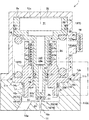
The pressure regulator valve 1 is a valve used to reduce the pressure of a working gas, mainly a high-pressure gas, to a working pressure or an atmospheric pressure. The pressure regulator valve is used by being interposed on, for example, a supply channel connected to a gas supply source, such as a high-pressure tank, or a discharge channel connected to the atmosphere. As shown in FIG. 1, the pressure regulator valve 1 includes a housing 2, a valve element 3, a tubular reinforcing body 4, a ball bearing 5, and a spring member 6.
The housing 2 is constituted by three members that are a base 11, a cover 12, and a body 13. It should be noted that the number of members of the housing 2 is not necessarily limited to three and may be four or more. The base 11 includes an insertion hole 14, a primary passage 15, and a secondary passage 16. The insertion hole 14 is formed along an axis L1 of the pressure regulator valve 1 on an attachment surface 11 c that is an upper surface of the base 11. The insertion hole 14 includes an opening 14 a on the attachment surface 11 c. The insertion hole 14 is a bottomed hole. The primary passage 15 and the secondary passage 16 are formed at a bottom portion that defines the insertion hole 14. The primary passage 15 is formed along the axis L1 of the pressure regulator valve 1 in an upper-lower direction and is connected to a primary port 15 a into which the working gas flows. The secondary passage 16 is formed at a position away from the primary passage 15 in a radially outer direction and extends obliquely downward in a direction away from the primary passage 15. The primary passage 15 and the secondary passage 16 are connected to the primary port 15 a and a secondary port 16 a, respectively. The primary passage 15, the secondary passage 16, a below-described primary region 23, and a below-described secondary region 24 (the regions 23 and 24 are regions included in the insertion hole 14) constitute a valve passage 19. An annular concave portion 11 a is formed around the opening 14 a of the base 11. The concave portion 11 a is lower than a portion located at a radially outer side of the concave portion 11 a. The attachment surface 11 c of the base 11 is formed in a step shape. The cover 12 is provided so as to contact a step upper portion 11 b and cover the opening 14 a. The step upper portion 11 b is the portion located at a radially outer side of the concave portion 11 a and is located higher than the concave portion 11 a.
The cover 12 is formed in a substantially cylindrical shape including a ceiling and opens downward. The cover 12 is formed such that an inner diameter thereof is substantially equal to an opening diameter of the concave portion 11 a of the base 11. A flange 12 b is formed at an opening end portion 12 a of the cover 12 over the entire periphery in a circumferential direction so as to extend in the radially outer direction. The flange 12 b is placed on the step upper portion 11 b of the base 11 and is fixed to the base 11 by a fastening member, such as a bolt (not shown). With this, the cover 12 is attached so as to contact the attachment surface 11 c of the base 11. The cover 12 covers the below-described body 13, and the body 13 is accommodated in the cover 12.
The body 13 is formed in a substantially cylindrical shape, and a tip end portion 13 a of the body 13 is inserted into and threadedly engaged with the insertion hole 14. An intermediate portion of the body 13 projects from the insertion hole 14 to an inside of the cover 12, and a flange 13 b is formed at the intermediate portion of the body 13 so as to extend in the radially outer direction. The flange 13 b is formed such that an outer diameter thereof is substantially equal to an inner diameter of the concave portion 11 a of the base 11. Apart of the flange 13 b is fitted in the concave portion 11 a. With this, a lower surface of the flange 13 b faces the attachment surface 11 c of the base 11. An upper portion of the flange 13 b projects from the concave portion 11 a to the inside of the cover 12 and is fitted to the cover 12 such that an outer peripheral surface thereof faces an inner peripheral surface of an opening-side portion of the cover 12. The body 13 arranged as above includes a through hole formed around the axis L1 and extending in the upper-lower direction. The valve element 3 is inserted into the through hole of the body 13 so as to be able to reciprocate in the upper-lower direction along the axis L1.
The valve element 3 is made of a soft material, such as an aluminum alloy, and is formed in a substantially columnar shape. Abase portion 3 a of the valve element 3 projects in the radially outer direction beyond a remaining portion of the valve element 3. The remaining portion of the valve element 3 is inserted into the body 13. A tip end portion 3 b of the valve element 3 projects downward from the tip end portion 13 a of the body 13. The tip end portion 3 b is opposed to an opening of the primary passage 15, and an annular projecting piece 20 is formed around the opening of the primary passage 15 so as to surround the opening. The valve element 3 includes a seat portion 21 at a position of the tip end portion 3 b which position is opposed to the projecting piece 20. The valve passage 19 opens when the valve element 3 is located at an open position (see FIG. 1) where the seat portion 21 and the projecting piece 20 are separated from each other. With this, an orifice 22 is formed between the seat portion 21 and the projecting piece 20, and the pressure of the working gas flowing through the valve passage 19 is reduced by the orifice 22. By the orifice 22, the insertion hole 14 is divided into a primary region 23 located inside the orifice 22 and a secondary region 24 located outside the orifice 22. The primary region 23 and the secondary region 24 are blocked from each other when the seat portion 21 is seated on the projecting piece 20 (i.e., the valve element 3 is located at a closed position), and this closes the orifice 22. When the primary region 23 and the secondary region 24 are blocked from each other, the valve passage 19 is closed. A tubular reinforcing body 4, called a bushing, is externally attached to an intermediate portion of the valve element 3.
The tubular reinforcing body 4 is a thin, cylindrical member made of a material (i.e., a hard material) harder than the material of the valve element 3. One example of the hard material is chromium molybdenum steel subjected to gas carburizing quenching. The tubular reinforcing body 4 is externally attached and fixed to the intermediate portion of the valve element 3 by press fitting. However, the method of externally attaching the tubular reinforcing body 4 is not limited to the press fitting. The intermediate portion of the valve element 3 is reinforced by the tubular reinforcing body 4 and is inserted into the body 13 with the tubular reinforcing body 4 attached thereto. A bearing accommodating space 25 that is a substantially cylindrical space is formed at the body 13 at a position around the intermediate portion of the valve element 3. More specifically, an inner peripheral surface of the body 13 includes an inward flange 13 c formed at the intermediate portion of the body 13 over the entire periphery in the circumferential direction, and the intermediate portion of the body 13 projects in a radially inner direction beyond a remaining portion of the body 13. With this, at a base end side of the body 13, the bearing accommodating space 25 that is a substantially cylindrical space is formed between the body 13 and the valve element 3. The ball bearing 5 is accommodated in the bearing accommodating space 25.
The ball bearing 5 is a so-called linear-motion ball guide and is formed in a substantially cylindrical shape. The ball bearing 5 is fittingly inserted in and fixed to an inner peripheral portion of the body 13 so as to be accommodated in the bearing accommodating space 25. The valve element 3 is inserted in the ball bearing 5 with the tubular reinforcing body 4 interposed therebetween. To be specific, the ball bearing 5 is externally attached to the tubular reinforcing body 4 attached to the intermediate portion of the valve element 3. With this, the valve element 3 is supported by the ball bearing 5 through the tubular reinforcing body 4 and can smoothly reciprocate in the upper-lower direction along the axis L1. According to prior art, since balls 5 a of the ball bearing 5 are brought into contact with the surface of the valve element 3, and the valve element 3 is directly supported by the ball bearing 5, the surface of a base material of the valve element 3 made of the soft material is subjected to plating to be hardened. However, in some cases, the base material of the valve element 3 is dented by surface pressure applied from the balls 5 a of the ball bearing 5, or the base material of the valve element 3 is damaged by peel-off of a plating layer formed on the surface of the valve element 3. By interposing the tubular reinforcing body 4, the balls 5 a of the ball bearing 5 can roll on an outer surface of the tubular reinforcing body 4, and the surface pressure generated by the balls 5 a can be received by the tubular reinforcing body 4 made of the hard material. Therefore, the base material of the valve element 3 can be prevented from deforming, and the durability of the valve element 3 can be improved.
As above, the intermediate portion of the valve element 3 is supported by the ball bearing 5 through the tubular reinforcing body 4 so as to be able to reciprocate. A tip end-side portion 3 c of the valve element 3 is a portion (except for the tip end portion 3 b) located at a tip end side of the tubular reinforcing body 4 and is inserted into the inward flange 13 c of the body 13. A seal groove 26 is formed on an outer peripheral surface of the tip end-side portion 3 c of the valve element 3 over the entire periphery in the circumferential direction.
A valve element seal 27, such as an O ring, is fitted in the seal groove 26. The valve element seal 27 contacts the inward flange 13 c to seal between the tip end-side portion 3 c and the inward flange 13 c. To be specific, the tip end-side portion 3 c of the valve element 3 is inserted in the inward flange 13 c in a sealed state and is guided by the inward flange 13 c so as to move along the axis L1.
The base portion 3 a of the valve element 3 is a portion located at a base end side of the tubular reinforcing body 4. The base portion 3 a of the valve element 3 projects from the body 13, and an outer diameter of the base portion 3 a is substantially equal to an inner diameter of the cover 12. Therefore, an outer peripheral surface of the base portion 3 a faces an inner peripheral surface of the cover 12, and a seal groove 28 is formed on the outer peripheral surface of the base portion 3 a over the entire periphery in the circumferential direction. A valve element seal 29, such as an O ring, is fitted in the seal groove 28. The valve element seal 29 contacts the inner peripheral surface of the cover 12 to seal between the base portion 3 a of the valve element 3 and the cover 12. To be specific, the base portion 3 a of the valve element 3 is fitted in the inner peripheral surface of the cover 12 in a sealed state and is guided by the cover 12 so as to reciprocate along the axis L1.
A spring receiving portion 3 d is formed at the base portion 3 a of the valve element 3. The spring receiving portion 3 d is formed at an outer peripheral edge portion of a lower surface of the base portion 3 a and is arranged so as to be opposed to an upper surface of the flange 13 b of the body 13. A cylindrical spring accommodating space 30 surrounded by the body 13 and the cover 12 is formed between the spring receiving portion 3 d and the flange 13 b. The spring member 6 is accommodated in the spring accommodating space 30. The spring member 6 is a so-called compression coil spring. Upper and lower end portions of the spring member 6 are supported by the spring receiving portion 3 d of the base portion 3 a and a spring receiving portion 13 d of the body 13, respectively. The spring receiving portion 13 d is an upper surface of the body 13. The spring member 6 is accommodated in the spring accommodating space 30 in a compressed state and biases the valve element 3 toward the open position. A secondary pressure (i.e., a pressure by which the valve element 3 is made to move toward the closed position) against the biasing force of the spring member 6 acts on the valve element 3. A concave space 31 is formed at the base portion 3 a of the valve element 3 so as to receive the secondary pressure.
The concave space 31 is formed at an upper surface of the base portion 3 a of the valve element 3 and extends along the axis L1. The concave space 31 is open toward a ceiling portion 12 c of the cover 12, and a secondary pressure chamber 32 including the concave space 31 is formed between the base portion 3 a of the valve element 3 and the ceiling portion 12 c of the cover 12. The secondary pressure chamber 32 is isolated from the spring accommodating space 30 by the valve element seal 29 and is connected to the secondary region 24 by a communication hole 33 and an annular passage 34 which are formed at the valve element 3.
The communication hole 33 includes a communicating portion 33 a and a connecting portion 33 b. The communicating portion 33 a extends from a bottom portion, defining the concave space 31, toward the tip end portion 3 b of the valve element 3 along the axis L1 of the valve element 3. A tip end side of the communication hole 33 extends to a position close to the tip end portion 3 b of the valve element 3, and the connecting portion 33 b is connected to a tip end-side portion of the communication hole 33. The connecting portion 33 b extends so as to penetrate the valve element 3 in a radial direction. Both ends of the connecting portion 33 b are open at an outer peripheral portion of the valve element 3, i.e., at one side of the tip end-side portion 3 c which side is located close to the tip end portion 3 b. A portion of the valve element 3 which portion is located at the above side of the tip end-side portion 3 b is smaller in diameter than the tip end-side portion 3 c, and the annular passage 34 is formed between the above portion of the valve element 3 and the inner peripheral surface of the body 13. The communication hole 33 is connected to the secondary region 24 through the annular passage 34. To be specific, the secondary region 24 communicates with the secondary pressure chamber 32 by the annular passage 34 and the communication hole 33, and the working gas introduced to the secondary region 24 is introduced to the secondary pressure chamber 32 through the annular passage 34 and the communication hole 33.
A base end of the valve element 3 forms a pressure receiving surface 3 e that receives the pressure (i.e., the secondary pressure) of the working gas introduced to the secondary pressure chamber 32. The valve element 3 is pushed toward the closed position by the secondary pressure. As above, the pressure receiving surface 3 e of the valve element 3 receives the secondary pressure introduced to the secondary pressure chamber 32, and the biasing force of the spring member 6 and the secondary pressure act on the valve element 3 so as to act against each other.
According to the pressure regulator valve 1 configured as above, the spring accommodating space 30 is isolated from the secondary region 24 (i.e., the valve passage 19) by the valve element seal 27 and is isolated from the secondary pressure chamber 32 by the valve element seal 29. Therefore, since the gas (i.e., air) in the spring accommodating space 30 expands or contracts by the movement of the valve element 3, an atmosphere communication hole 35 is formed at the cover 12 in order to prevent such expansion and contraction. The atmosphere communication hole 35 opens the spring accommodating space 30 to the atmosphere. Thus, the air in the spring accommodating space 30 can be released to the atmosphere, and the air can be sucked from the atmosphere into the spring accommodating space 30. A cap member 36 is fitted and fixed to the atmosphere communication hole 35. The cap member 36 prevents a liquid, such as rain water, from flowing therethrough while allowing a gas, such as air, to flow therethrough. With this, a liquid, such as rain water, can be prevented from flowing into the spring accommodating space 30.
A gas seal 37 and a waterproof seal 38 are provided at the housing 2. Hereinafter, positions where the gas seal 37 and the waterproof seal 38 are arranged will be explained also with reference to FIG. 2. The gas seal 37 prevents the working gas from flowing out from the valve passage 19 to the cover 12, the atmosphere, and the like. The gas seal 37 is constituted by an O ring made of, for example, synthetic rubber and is externally attached to the tip end portion 13 a of the body 13.
More specifically, the gas seal 37 is externally attached to the tip end portion 13 a of the body 13 while contacting the lower surface of the flange 13 b of the body 13. When the body 13 is inserted into the insertion hole 14 and threadedly engaged with the base 11, the gas seal 37 is crushed by the tip end portion 13 a, the flange 13 b, and the base 11 to seal between the tip end portion 13 a and the base 11. With this, the valve passage 19 can be isolated from the spring accommodating space 30 and the atmosphere by the gas seal 37, and the working gas flowing through the valve passage 19 can be prevented from flowing out to the spring accommodating space 30 and the atmosphere.
The waterproof seal 38 prevents a liquid, such as rain water, from flowing into the pressure regulator valve 1 and is constituted by an O ring made of, for example, synthetic rubber. A seal accommodating space 39 at which the waterproof seal 38 is arranged is formed at the housing 2. More specifically, as shown in FIG. 3, a step portion 12 d is formed at an inner peripheral edge of the opening end portion 12 a of the cover 12 of the housing 2. By bringing the opening end portion 12 a of the cover 12 into contact with the step upper portion 11 b of the base 11, the seal accommodating space 39 is formed by the step portion 12 d. The seal accommodating space 39 is an annular space formed at an inner peripheral surface of the housing 2 over the entire periphery in the circumferential direction. The seal accommodating space 39 includes a surface opening 39 a located at a radially inner side and facing an outer peripheral surface of the flange 13 b of the body 13. An annular gap 40 is formed between the outer peripheral surface of the flange 13 b and the inner peripheral surface of the cover 12, and the seal accommodating space 39 faces the gap 40.
The waterproof seal 38 is accommodated in the seal accommodating space 39 formed as above and is arranged so as not to close the gap 40. To be specific, the waterproof seal 38 is formed such that: an inner diameter thereof is larger than an inner diameter of the cover 12; and even when the waterproof seal 38 is accommodated in the seal accommodating space 39 and crushed by the cover 12 and the base 11, at least a part of the waterproof seal 38 does not contact the outer peripheral surface of the flange 13 b. In the present embodiment, the waterproof seal 38 is formed so as to be separated from the outer peripheral surface of the flange 13 b over the entire periphery in the circumferential direction. With this, the waterproof seal 38 can seal between the flange 12 b of the cover 12 and the step upper portion 11 b of the base 11 without closing the gap 40 between the outer peripheral surface of the flange 13 b and the inner peripheral surface of the cover 12. Thus, a liquid, such as rain water, can be prevented from flowing from between the flange 12 b and the step upper portion 11 b into the valve passage 19 and the spring accommodating space 30, and the gas leaking from the gas seal 37 can be introduced to the spring accommodating space 30 to be released to the atmosphere through the atmosphere communication hole 35. Therefore, a pressure increase caused when the working gas leaking from the gas seal 37 is accumulated between the flange 13 b and the concave portion 11 a can be prevented from occurring, and the body 13 can be prevented from being lifted by the pressure increase.
Operations of Pressure Regulator Valve
Hereinafter, operations of the pressure regulator valve 1 in reducing the pressure of the working gas, such as a high-pressure gas, introduced to the primary port 15 a will be explained with reference to FIG. 1. Examples of the working gas include a corrosive gas (such as a sulfur gas) and a non-corrosive gas (such as high-pressure air). Since the valve element 3 is being biased in an open direction by the spring member 6, the pressure regulator valve 1 is normally open, and the high-pressure gas introduced to the primary port 15 a is introduced through the orifice 22 to the secondary region 24. When the high-pressure gas flows through the orifice 22, the pressure of the high-pressure gas is reduced from the primary pressure to the secondary pressure. Then, the gas is introduced to the secondary region 24 to be supplied through the secondary passage 16 and the secondary port 16 a to a downstream device.
The gas having the low pressure reduced as above is also introduced through the annular passage 34 and the communication hole 33 to the secondary pressure chamber 32 in addition to the secondary passage 16. With this, the secondary pressure acts on the pressure receiving surface 3 e of the valve element 3 to push the valve element 3 toward the closed position. With this, the valve element 3 moves in such a direction as to close the orifice 22. Thus, the valve element 3 moves to a position where an acting force generated by the secondary pressure received by the pressure receiving surface 3 e, the biasing force of the spring member 6, and other forces acting on the valve element 3 are balanced. For example, when the secondary pressure decreases, the acting force acting on the pressure receiving surface 3 e decreases, and the biasing force of the spring member 6 exceeds the acting force acting on the pressure receiving surface 3 e. In this case, in order to keep the balance between the acting force acting on the pressure receiving surface 3 e and the biasing force of the spring member 6, the valve element 3 moves toward the open position to open the orifice 22. With this, the secondary pressure increases and is kept at a set pressure.
According to the pressure regulator valve 1, since the ball bearing 5 is adopted as a member supporting the valve element 3, the valve element 3 can smoothly reciprocate, and therefore, the responsiveness can be improved. Further, according to the pressure regulator valve 1, as described above, the ball bearing 5 supports the valve element 3 through the tubular reinforcing body 4. Therefore, even when the valve element 3 receives significant surface pressure from the balls 5 a, the valve element 3 can be prevented from deforming. With this, the valve element 3 does not have to be subjected to a hardening treatment, and the valve element 3 can be prevented from being damaged.
Embodiment 2
The pressure regulator valve 1A of Embodiment 2 is similar in configuration to the pressure regulator valve 1 of Embodiment 1. Hereinafter, components of the pressure regulator valve 1A which are different from the components of the pressure regulator valve 1 of Embodiment 1 will be mainly explained, and explanations of the same components are omitted.
According to the pressure regulator valve 1A of Embodiment 2, a waterproof seal 38A is formed such that an inner diameter thereof is substantially equal to the outer diameter of the flange 13 b. The waterproof seal 38A is accommodated in the seal accommodating space 39 while being crushed by the cover 12 and the base 11. While being crushed by the cover 12 and the base 11, the waterproof seal 38A contacts the outer peripheral surface of the flange 13 b over the entire periphery in the circumferential direction. With this, the waterproof seal 38A can seal between the flange 12 b of the cover 12 and the step upper portion 11 b of the base 11 and close the gap 40 between the outer peripheral surface of the flange 13 b and the inner peripheral surface of the cover 12.
The waterproof seal 38A arranged as above is made of a porous material, such as porous PTFE. The waterproof seal 38A can prevent a liquid, such as rain water, from flowing therethrough and allow the working gas to flow therethrough. To be specific, the waterproof seal 38A includes therein a channel through which the working gas flows. Therefore, the flow of a liquid, such as rain water, from between the flange 12 b and the step upper portion 11 b into the valve passage 19 and the spring accommodating space 30 can be prevented by the waterproof seal 38A, and the gas leaking from the gas seal 37 can be released to the atmosphere from between the flange 12 b and the step upper portion 11 b. The atmosphere flowing into between the flange 12 b and the step upper portion 11 b can be made to flow into the spring accommodating space 30 through an inside of the waterproof seal 38A and the gap 40, and in contrast, the gas (such as air) in the spring accommodating space 30 can be released to the atmosphere through the gap 40 and the inside of the waterproof seal 38A. With this, when the volume of the spring accommodating space 30 changes by the movement of the valve element 3, the gas can be taken into the spring accommodating space 30 through the gap 40 from the atmosphere, or the gas in the spring accommodating space 30 can be released to the atmosphere through the gap 40. Therefore, the atmosphere communication hole 35 and the cap member 36 can be omitted, and this can reduce the number of parts. It should be noted that the atmosphere communication hole 35 and the cap member 36 do not have to be omitted and may be formed and provided at the cover 12 as with the pressure regulator valve 1 of Embodiment 1.
Further, since the waterproof seal 38A is arranged so as to contact the flange 13 b, the waterproof seal 38A can be arranged so as to be fitted to the flange 13 b. With this, the waterproof seal 38A is easily positioned, and the waterproof seal 38A can be easily attached.
The pressure regulator valve 1A of Embodiment 2 has the same operational advantages as the pressure regulator valve 1 of Embodiment 1.
Other Embodiment
According to the pressure regulator valve 1 of Embodiment 1, in order not to close the gap 40, the shape of the waterproof seal 38 is designed, and the waterproof seal 38 is arranged. However, as in a pressure regulator valve 1B shown in FIG. 4, the gap 40 may be closed by the waterproof seal 38. In this case, a pressure release hole 41 is formed at the flange 13 b. With this, the gas accumulated between the gas seal 37 and the waterproof seal 38 can be released to the spring accommodating space 30 through the pressure release hole 41. Thus, the pressure regulator valve having the same operational advantages as the pressure regulator valve 1 of Embodiment 1 can be configured. Further, the gap 40 does not necessarily have to be aggressively formed as in FIG. 2. To be specific, the gap 40 may be a slight gap formed when two members are brought into contact with each other. The gap 40 is only required to be a gap through which a gas flows.
According to the pressure regulator valves 1, 1A, and 1B of Embodiments 1, 2, and 3, the flange 13 b is formed at the body 13. However, the flange 13 b does not necessarily have to be formed. In this case, the outer peripheral surface of the body 13 is fitted to the cover 12.
From the foregoing explanation, many modifications and other embodiments of the present invention are obvious to one skilled in the art. Therefore, the foregoing explanation should be interpreted only as an example and is provided for the purpose of teaching the best mode for carrying out the present invention to one skilled in the art. The structures and/or functional details may be substantially modified within the scope of the present invention.
REFERENCE SIGNS LIST
    • 1, 1A, 1B pressure regulator valve
    • 2 housing
    • 3 valve element
    • 6 spring member
    • 11 base
    • 12 cover
    • 13 body
    • 14 a opening
    • 15 primary passage
    • 16 secondary passage
    • 19 valve passage
    • 30 spring accommodating chamber
    • 36 cap member (sealing member)
    • 37 gas seal (first sealing member)
    • 38, 38A waterproof sealing member (second sealing member)
    • 41 pressure release hole

Claims (4)

The invention claimed is:
1. A pressure regulator valve comprising:
a housing including
a base including a valve passage through which a working gas flows,
a tubular body attached to the base, and
a cover attached to the base so as to cover the body;
a valve element configured to open and close the valve passage by moving between a closed position where the valve element closes the valve passage and an open position where the valve element opens the valve passage, the valve element being further configured to reduce a primary pressure to a secondary pressure and receive the secondary pressure by which the valve element moves toward the closed position;
a biasing unit accommodated in an accommodating space formed between the body and the cover, the biasing unit being configured to bias the valve element such that the valve element moves toward the open position;
a first sealing member provided between the base and the body; and
a second sealing member provided between the base and the cover and made of synthetic rubber, wherein
the second sealing member is arranged away from the body, and
an annular gap communicating with the accommodating space is formed between an outermost outer peripheral surface of the body and an inner peripheral surface of the cover.
2. The pressure regulator valve according to claim 1, wherein:
the cover includes an atmosphere communication hole through which the accommodating space communicates with an atmosphere;
the atmosphere communication hole is closed by a sealing member; and
the sealing member allows a gas to flow therethrough and prevents a liquid from flowing therethrough.
3. A pressure regulator valve comprising:
a housing including
a base including a valve passage through which a working gas flows,
a tubular body attached to the base, and
a cover attached to the base so as to cover the body;
a valve element configured to open and close the valve passage by moving between a closed position where the valve element closes the valve passage and an open position where the valve element opens the valve passage, the valve element being further configured to reduce a primary pressure to a secondary pressure and receive the secondary pressure by which the valve element moves toward the closed position;
a biasing unit accommodated in an accommodating space formed between the body and the cover, the biasing unit being configured to bias the valve element such that the valve element moves toward the open position;
a first sealing member provided between the base and the body to seal the valve passage; and
a second sealing member provided between the base and the cover, wherein:
the second sealing member is made of a porous material which allows a gas to flow therethrough and prevents a liquid from flowing therethrough; and
the second sealing member is arranged so as to contact the body.
4. A pressure regulator valve comprising:
a housing including
a base including a valve passage through which a working gas flows,
a tubular body attached to the base, and
a cover attached to the base so as to cover the body;
a valve element configured to open and close the valve passage by moving between a closed position where the valve element closes the valve passage and an open position where the valve element opens the valve passage, the valve element being further configured to reduce a primary pressure to a secondary pressure and receive the secondary pressure by which the valve element moves toward the closed position;
a biasing unit accommodated in an accommodating space formed between the body and the cover, the biasing unit being configured to bias the valve element such that the valve element moves toward the open position;
a first sealing member provided at a gap between the base and the body; and
a second sealing member provided at a gap between the base and the cover and made of synthetic rubber, wherein:
the second sealing member is arranged so as to contact the body; and
the body includes a pressure release hole connecting the accommodating space and a gap between the base and the body, the gap being a portion located at an opposite side of the valve passage across the first sealing member.
US16/316,008 2016-07-07 2017-06-12 Pressure regulator valve Active 2037-06-14 US10907745B2 (en)

Applications Claiming Priority (3)

Application Number Priority Date Filing Date Title
JP2016135052A JP6755732B2 (en) 2016-07-07 2016-07-07 Pressure reducing valve
JP2016-135052 2016-07-07
PCT/JP2017/021657 WO2018008335A1 (en) 2016-07-07 2017-06-12 Pressure reducing valve

Publications (2)

Publication Number Publication Date
US20190277418A1 US20190277418A1 (en) 2019-09-12
US10907745B2 true US10907745B2 (en) 2021-02-02

Family

ID=60912115

Family Applications (1)

Application Number Title Priority Date Filing Date
US16/316,008 Active 2037-06-14 US10907745B2 (en) 2016-07-07 2017-06-12 Pressure regulator valve

Country Status (6)

Country Link
US (1) US10907745B2 (en)
EP (1) EP3483693B1 (en)
JP (1) JP6755732B2 (en)
KR (1) KR20190034212A (en)
CN (1) CN109416548B (en)
WO (1) WO2018008335A1 (en)

Families Citing this family (2)

* Cited by examiner, † Cited by third party
Publication number Priority date Publication date Assignee Title
JP6356645B2 (en) * 2015-09-04 2018-07-11 株式会社鷺宮製作所 Throttle device and refrigeration cycle
JP7216497B2 (en) * 2018-08-20 2023-02-01 川崎重工業株式会社 Pressure reducing valve

Citations (21)

* Cited by examiner, † Cited by third party
Publication number Priority date Publication date Assignee Title
US2027762A (en) * 1933-07-17 1936-01-14 Jeddo Highland Coal Company Valve
US2563192A (en) * 1946-08-26 1951-08-07 Hpm Dev Corp Apparatus for controlling fluid pressures
US2680454A (en) * 1950-08-01 1954-06-08 Us Army Regulator valve
US2700983A (en) * 1952-03-04 1955-02-01 Grove Valve & Regulator Co Fluid pressure regulator
US3087705A (en) * 1961-04-18 1963-04-30 Weatherhead Co Adjustable valve head
US3698425A (en) * 1970-02-03 1972-10-17 U S Divers Co Adjustable breathing gas pressure regulator
US4015630A (en) * 1975-10-23 1977-04-05 Pittman Products, Inc. Regulator first stage for underwater diving
US4226257A (en) * 1978-03-30 1980-10-07 Sherwood-Selpac Corporation Scuba regulator
US5662100A (en) * 1996-01-11 1997-09-02 Harsco Corporation Eductive pressure regulator
JPH106950A (en) 1996-06-20 1998-01-13 Tokico Ltd Hydraulic control valve
US5860447A (en) * 1996-05-10 1999-01-19 Chu; David In line pressure regulator valve with passive pressure release
US6257275B1 (en) * 2000-04-17 2001-07-10 Liberty Group Pressure reducing valve
JP2005149172A (en) 2003-11-17 2005-06-09 Nec Engineering Ltd Pressure-regulating adapter structure with function to protect filter membrane
US20050152796A1 (en) * 2002-05-06 2005-07-14 Morrison Walter G. Pressure control valve
JP2006146776A (en) 2004-11-24 2006-06-08 Kawasaki Precision Machinery Ltd Pressure reducing valve
JP2006260385A (en) 2005-03-18 2006-09-28 Osaka Gas Co Ltd Pressure governor and processing method
US20080302428A1 (en) * 2007-06-07 2008-12-11 Kaoru Nomichi Pressure-reducing valve
US7798169B2 (en) * 2007-11-28 2010-09-21 Su-Hua Tai One-piece gas pressure regulator
JP2010255642A (en) 2009-04-21 2010-11-11 Nok Corp Sealing device
WO2012056647A1 (en) 2010-10-25 2012-05-03 川崎重工業株式会社 Decompression valve
WO2015052863A1 (en) 2013-10-09 2015-04-16 川崎重工業株式会社 Pressure reducing valve

Family Cites Families (8)

* Cited by examiner, † Cited by third party
Publication number Priority date Publication date Assignee Title
AU2003221330A1 (en) * 2002-03-07 2003-09-16 Toto Ltd. Pressure reducing valve
CN1800624A (en) * 2004-10-28 2006-07-12 白天海 Multifunctional spark plug
US20120227389A1 (en) * 2008-04-16 2012-09-13 Hinderks M V Reciprocating machine & other devices
US9074703B2 (en) * 2008-10-28 2015-07-07 GM Global Technology Operations LLC Pressure regulator for hydrogen storage system
JP5168677B2 (en) * 2008-11-18 2013-03-21 トヨタ自動車株式会社 High pressure tank
JP5116807B2 (en) * 2010-06-15 2013-01-09 本田技研工業株式会社 Pressure vessel
JP2013025672A (en) * 2011-07-25 2013-02-04 Aisan Ind Co Ltd Regulator for fluid
CN203230922U (en) * 2013-05-17 2013-10-09 瑞立集团瑞安汽车零部件有限公司 Waterproof type electromagnetic valve

Patent Citations (22)

* Cited by examiner, † Cited by third party
Publication number Priority date Publication date Assignee Title
US2027762A (en) * 1933-07-17 1936-01-14 Jeddo Highland Coal Company Valve
US2563192A (en) * 1946-08-26 1951-08-07 Hpm Dev Corp Apparatus for controlling fluid pressures
US2680454A (en) * 1950-08-01 1954-06-08 Us Army Regulator valve
US2700983A (en) * 1952-03-04 1955-02-01 Grove Valve & Regulator Co Fluid pressure regulator
US3087705A (en) * 1961-04-18 1963-04-30 Weatherhead Co Adjustable valve head
US3698425A (en) * 1970-02-03 1972-10-17 U S Divers Co Adjustable breathing gas pressure regulator
US4015630A (en) * 1975-10-23 1977-04-05 Pittman Products, Inc. Regulator first stage for underwater diving
US4226257A (en) * 1978-03-30 1980-10-07 Sherwood-Selpac Corporation Scuba regulator
US5662100A (en) * 1996-01-11 1997-09-02 Harsco Corporation Eductive pressure regulator
US5860447A (en) * 1996-05-10 1999-01-19 Chu; David In line pressure regulator valve with passive pressure release
JPH106950A (en) 1996-06-20 1998-01-13 Tokico Ltd Hydraulic control valve
US6257275B1 (en) * 2000-04-17 2001-07-10 Liberty Group Pressure reducing valve
US20050152796A1 (en) * 2002-05-06 2005-07-14 Morrison Walter G. Pressure control valve
JP2005149172A (en) 2003-11-17 2005-06-09 Nec Engineering Ltd Pressure-regulating adapter structure with function to protect filter membrane
JP2006146776A (en) 2004-11-24 2006-06-08 Kawasaki Precision Machinery Ltd Pressure reducing valve
JP2006260385A (en) 2005-03-18 2006-09-28 Osaka Gas Co Ltd Pressure governor and processing method
US20080302428A1 (en) * 2007-06-07 2008-12-11 Kaoru Nomichi Pressure-reducing valve
US7798169B2 (en) * 2007-11-28 2010-09-21 Su-Hua Tai One-piece gas pressure regulator
JP2010255642A (en) 2009-04-21 2010-11-11 Nok Corp Sealing device
WO2012056647A1 (en) 2010-10-25 2012-05-03 川崎重工業株式会社 Decompression valve
US20130263942A1 (en) 2010-10-25 2013-10-10 Kawasaki Jukogyo Kabushiki Kaisha Pressure reducing valve
WO2015052863A1 (en) 2013-10-09 2015-04-16 川崎重工業株式会社 Pressure reducing valve

Also Published As

Publication number Publication date
WO2018008335A1 (en) 2018-01-11
EP3483693A1 (en) 2019-05-15
EP3483693B1 (en) 2021-08-04
US20190277418A1 (en) 2019-09-12
KR20190034212A (en) 2019-04-01
EP3483693A4 (en) 2020-03-04
CN109416548A (en) 2019-03-01
JP6755732B2 (en) 2020-09-16
JP2018005769A (en) 2018-01-11
CN109416548B (en) 2022-01-14

Similar Documents

Publication Publication Date Title
KR100889577B1 (en) Diaphragm valve
US7063304B2 (en) Extended stroke valve and diaphragm
CA1045105A (en) High pressure diaphragm valve
CA2711820C (en) Control valve trim and seal
US20130341550A1 (en) Two-way valve
US10907745B2 (en) Pressure regulator valve
JP2008309255A (en) Relief valve
US3631882A (en) Diaphragm valve
KR101667593B1 (en) A control valve for cryogenic high pressure gas which having reinforced sealing member
US20130312840A1 (en) Valve actuator system
US10584796B2 (en) Seal, assembly, and retention method
RU2672535C2 (en) Actuator bushing having integral seals (options)
KR20210015764A (en) Pinch valve
AU2010210501B2 (en) Pressure-balanced control valves
US20200370664A1 (en) Valve device and fluid control device
US10359119B2 (en) High pressure valve
JP5248660B2 (en) Diaphragm valve
JP7216497B2 (en) Pressure reducing valve
US9777854B2 (en) Safety valve
JP5764315B2 (en) Diaphragm valve
JP4813047B2 (en) Diaphragm valve
JP2010144765A (en) Diaphragm valve
JP2015075930A (en) Pressure-reducing valve
KR102338790B1 (en) Valve with Metal Seal for Improving Airtightness Efficiency
US7077384B2 (en) Integrated post-guided seat ring assembly

Legal Events

Date Code Title Description
FEPP Fee payment procedure

Free format text: ENTITY STATUS SET TO UNDISCOUNTED (ORIGINAL EVENT CODE: BIG.); ENTITY STATUS OF PATENT OWNER: LARGE ENTITY

AS Assignment

Owner name: KAWASAKI JUKOGYO KABUSHIKI KAISHA, JAPAN

Free format text: ASSIGNMENT OF ASSIGNORS INTEREST;ASSIGNORS:SUZUKI, YUTAKA;YAMASHITA, HIROSHI;SAKAI, KAZUMASA;AND OTHERS;SIGNING DATES FROM 20190109 TO 20190117;REEL/FRAME:048604/0457

STPP Information on status: patent application and granting procedure in general

Free format text: DOCKETED NEW CASE - READY FOR EXAMINATION

STPP Information on status: patent application and granting procedure in general

Free format text: FINAL REJECTION MAILED

STPP Information on status: patent application and granting procedure in general

Free format text: PUBLICATIONS -- ISSUE FEE PAYMENT RECEIVED

STCF Information on status: patent grant

Free format text: PATENTED CASE