US10893502B2 - Range-finding and object-positioning systems and methods using same - Google Patents
Range-finding and object-positioning systems and methods using same Download PDFInfo
- Publication number
- US10893502B2 US10893502B2 US16/919,822 US202016919822A US10893502B2 US 10893502 B2 US10893502 B2 US 10893502B2 US 202016919822 A US202016919822 A US 202016919822A US 10893502 B2 US10893502 B2 US 10893502B2
- Authority
- US
- United States
- Prior art keywords
- target device
- speed signal
- determining
- speed
- signal
- Prior art date
- Legal status (The legal status is an assumption and is not a legal conclusion. Google has not performed a legal analysis and makes no representation as to the accuracy of the status listed.)
- Active
Links
- 238000000034 method Methods 0.000 title claims description 43
- 230000005540 biological transmission Effects 0.000 claims abstract description 42
- 238000012545 processing Methods 0.000 claims abstract description 30
- 230000008569 process Effects 0.000 claims description 12
- 238000004891 communication Methods 0.000 claims description 9
- 238000004422 calculation algorithm Methods 0.000 claims description 4
- 238000007476 Maximum Likelihood Methods 0.000 claims description 3
- 230000008878 coupling Effects 0.000 claims 1
- 238000010168 coupling process Methods 0.000 claims 1
- 238000005859 coupling reaction Methods 0.000 claims 1
- 238000005259 measurement Methods 0.000 description 19
- 238000005070 sampling Methods 0.000 description 8
- 239000003999 initiator Substances 0.000 description 7
- 230000005236 sound signal Effects 0.000 description 6
- 238000004590 computer program Methods 0.000 description 4
- 238000005516 engineering process Methods 0.000 description 4
- 238000001914 filtration Methods 0.000 description 4
- 210000000707 wrist Anatomy 0.000 description 4
- 239000003570 air Substances 0.000 description 3
- 238000004364 calculation method Methods 0.000 description 3
- 238000010586 diagram Methods 0.000 description 3
- 230000003287 optical effect Effects 0.000 description 3
- 230000003190 augmentative effect Effects 0.000 description 2
- 230000007613 environmental effect Effects 0.000 description 2
- 230000000977 initiatory effect Effects 0.000 description 2
- 239000011159 matrix material Substances 0.000 description 2
- 238000012935 Averaging Methods 0.000 description 1
- 239000012080 ambient air Substances 0.000 description 1
- 230000008901 benefit Effects 0.000 description 1
- 238000006243 chemical reaction Methods 0.000 description 1
- 238000012937 correction Methods 0.000 description 1
- 230000003111 delayed effect Effects 0.000 description 1
- 238000013461 design Methods 0.000 description 1
- 238000001514 detection method Methods 0.000 description 1
- 239000004744 fabric Substances 0.000 description 1
- PCHJSUWPFVWCPO-UHFFFAOYSA-N gold Chemical compound [Au] PCHJSUWPFVWCPO-UHFFFAOYSA-N 0.000 description 1
- 239000010931 gold Substances 0.000 description 1
- 229910052737 gold Inorganic materials 0.000 description 1
- 210000004247 hand Anatomy 0.000 description 1
- 230000003116 impacting effect Effects 0.000 description 1
- 239000007788 liquid Substances 0.000 description 1
- 239000000463 material Substances 0.000 description 1
- 238000012986 modification Methods 0.000 description 1
- 230000004048 modification Effects 0.000 description 1
- 238000003672 processing method Methods 0.000 description 1
- 230000009467 reduction Effects 0.000 description 1
- 230000004044 response Effects 0.000 description 1
- 239000004065 semiconductor Substances 0.000 description 1
- 239000007787 solid Substances 0.000 description 1
- 238000002604 ultrasonography Methods 0.000 description 1
Images


Classifications
-
- H—ELECTRICITY
- H04—ELECTRIC COMMUNICATION TECHNIQUE
- H04W—WIRELESS COMMUNICATION NETWORKS
- H04W64/00—Locating users or terminals or network equipment for network management purposes, e.g. mobility management
- H04W64/006—Locating users or terminals or network equipment for network management purposes, e.g. mobility management with additional information processing, e.g. for direction or speed determination
-
- G—PHYSICS
- G01—MEASURING; TESTING
- G01S—RADIO DIRECTION-FINDING; RADIO NAVIGATION; DETERMINING DISTANCE OR VELOCITY BY USE OF RADIO WAVES; LOCATING OR PRESENCE-DETECTING BY USE OF THE REFLECTION OR RERADIATION OF RADIO WAVES; ANALOGOUS ARRANGEMENTS USING OTHER WAVES
- G01S1/00—Beacons or beacon systems transmitting signals having a characteristic or characteristics capable of being detected by non-directional receivers and defining directions, positions, or position lines fixed relatively to the beacon transmitters; Receivers co-operating therewith
- G01S1/72—Beacons or beacon systems transmitting signals having a characteristic or characteristics capable of being detected by non-directional receivers and defining directions, positions, or position lines fixed relatively to the beacon transmitters; Receivers co-operating therewith using ultrasonic, sonic or infrasonic waves
- G01S1/74—Details
- G01S1/75—Transmitters
- G01S1/753—Signal details
-
- G—PHYSICS
- G01—MEASURING; TESTING
- G01S—RADIO DIRECTION-FINDING; RADIO NAVIGATION; DETERMINING DISTANCE OR VELOCITY BY USE OF RADIO WAVES; LOCATING OR PRESENCE-DETECTING BY USE OF THE REFLECTION OR RERADIATION OF RADIO WAVES; ANALOGOUS ARRANGEMENTS USING OTHER WAVES
- G01S11/00—Systems for determining distance or velocity not using reflection or reradiation
- G01S11/16—Systems for determining distance or velocity not using reflection or reradiation using difference in transit time between electrical and acoustic signals
-
- G—PHYSICS
- G01—MEASURING; TESTING
- G01S—RADIO DIRECTION-FINDING; RADIO NAVIGATION; DETERMINING DISTANCE OR VELOCITY BY USE OF RADIO WAVES; LOCATING OR PRESENCE-DETECTING BY USE OF THE REFLECTION OR RERADIATION OF RADIO WAVES; ANALOGOUS ARRANGEMENTS USING OTHER WAVES
- G01S5/00—Position-fixing by co-ordinating two or more direction or position line determinations; Position-fixing by co-ordinating two or more distance determinations
- G01S5/0009—Transmission of position information to remote stations
- G01S5/0018—Transmission from mobile station to base station
- G01S5/0036—Transmission from mobile station to base station of measured values, i.e. measurement on mobile and position calculation on base station
-
- G—PHYSICS
- G01—MEASURING; TESTING
- G01S—RADIO DIRECTION-FINDING; RADIO NAVIGATION; DETERMINING DISTANCE OR VELOCITY BY USE OF RADIO WAVES; LOCATING OR PRESENCE-DETECTING BY USE OF THE REFLECTION OR RERADIATION OF RADIO WAVES; ANALOGOUS ARRANGEMENTS USING OTHER WAVES
- G01S5/00—Position-fixing by co-ordinating two or more direction or position line determinations; Position-fixing by co-ordinating two or more distance determinations
- G01S5/18—Position-fixing by co-ordinating two or more direction or position line determinations; Position-fixing by co-ordinating two or more distance determinations using ultrasonic, sonic, or infrasonic waves
- G01S5/30—Determining absolute distances from a plurality of spaced points of known location
-
- H—ELECTRICITY
- H04—ELECTRIC COMMUNICATION TECHNIQUE
- H04L—TRANSMISSION OF DIGITAL INFORMATION, e.g. TELEGRAPHIC COMMUNICATION
- H04L1/00—Arrangements for detecting or preventing errors in the information received
- H04L1/004—Arrangements for detecting or preventing errors in the information received by using forward error control
- H04L1/0045—Arrangements at the receiver end
- H04L1/0054—Maximum-likelihood or sequential decoding, e.g. Viterbi, Fano, ZJ algorithms
-
- H—ELECTRICITY
- H04—ELECTRIC COMMUNICATION TECHNIQUE
- H04L—TRANSMISSION OF DIGITAL INFORMATION, e.g. TELEGRAPHIC COMMUNICATION
- H04L5/00—Arrangements affording multiple use of the transmission path
- H04L5/003—Arrangements for allocating sub-channels of the transmission path
- H04L5/0048—Allocation of pilot signals, i.e. of signals known to the receiver
-
- G—PHYSICS
- G01—MEASURING; TESTING
- G01S—RADIO DIRECTION-FINDING; RADIO NAVIGATION; DETERMINING DISTANCE OR VELOCITY BY USE OF RADIO WAVES; LOCATING OR PRESENCE-DETECTING BY USE OF THE REFLECTION OR RERADIATION OF RADIO WAVES; ANALOGOUS ARRANGEMENTS USING OTHER WAVES
- G01S1/00—Beacons or beacon systems transmitting signals having a characteristic or characteristics capable of being detected by non-directional receivers and defining directions, positions, or position lines fixed relatively to the beacon transmitters; Receivers co-operating therewith
- G01S1/72—Beacons or beacon systems transmitting signals having a characteristic or characteristics capable of being detected by non-directional receivers and defining directions, positions, or position lines fixed relatively to the beacon transmitters; Receivers co-operating therewith using ultrasonic, sonic or infrasonic waves
- G01S1/76—Systems for determining direction or position line
- G01S1/80—Systems for determining direction or position line using a comparison of transit time of synchronised signals transmitted from non-directional transducers or transducer systems spaced apart, i.e. path-difference systems
Definitions
- the present invention relates generally to range-finding and object-positioning methods and systems, and in particular to mixed mode range-finding and object-positioning systems and methods of finding the distance between a reference object and a target object, and methods of determining the position of an object using same.
- rangefinders are known, for example, one type of rangefinder generally comprises an infrared light emitting diode (LED) and a photodiode.
- the rangefinder emits an infrared pulse, which is reflected by a nearby object.
- the rangefinder receives the reflected infrared signal. Characteristics of the reflected infrared signal such as intensity, time of flight, frequency and/or phase are then analyzed to derive the object's range.
- An emitter for example, a narrow beam width antenna such as a parabolic antenna, emits a radio frequency pulse (sometimes denoted as a signal beam).
- Radio reflective materials of objects within the signal beam reflect the signal back to the emitter. Measurements of the reflected signal's time of flight and Doppler shift are then used to compute the object's range, and in some systems, velocity.
- Range-finding systems and methods i.e., systems and methods for determining the distance between two objects
- object positioning systems usually use range-finding methods to first determine the distance between a target object and each of one or more reference objects, and then determining the position of the target object.
- Examples of known object positioning systems include the Global Positioning System (GPS) of the United States, the Global Navigation Satellite System (GLONASS) of Russia, the Galileo positioning system of the European Union, and the BeiDou Navigation Satellite System of China.
- a difficulty with these systems is that the propagation speed of the emitted radio frequency (RF) signal, which is substantially the speed of light, is so high that even small errors in time of flight measurement amount to large errors in distance calculation, which results in more stringent and costly system requirements, e.g., precise time synchronization, wide signal bandwidth, and the like.
- RF radio frequency
- a ranging apparatus comprises: at least one signal receiver for receiving at least one set of signals transmitted from at least one location, each of the at least one set of signals comprising at least a first-speed signal having a first transmission speed and a second-speed signal having a second transmission speed, and the first transmission speed being higher than the second transmission speed; and at least one processing unit for determining the distance between the apparatus and each of the at least one location based on the time difference between the time of receiving the first-speed signal transmitted from said location and the time of receiving the second-speed signal transmitted from said location.
- the distance between the apparatus and each of the at least one location is determined as:
- d c 1 ⁇ c 2 ⁇ ⁇ ⁇ t c 1 - c 2 , ( 1 ) wherein d is the distance between the apparatus and said location, ⁇ t is the time difference between the time of receiving the first-speed signal transmitted from said location and the time of receiving the second-speed signal transmitted from said location, c 1 is the first speed, c 2 is the second speed, and c 1 >c 2 .
- the first-speed signal is a Radio Frequency (RF) signal
- the second-speed signal is an acoustic signal.
- An acoustic signal is a mechanical wave that propagates in a medium, such as a gas (e.g., air), liquid or solid as vibration, audio signal, sound, ultrasound (i.e., ultrasonic signal) and/or infrasound, whether audible or inaudible.
- a gas e.g., air
- ultrasound i.e., ultrasonic signal
- infrasound whether audible or inaudible.
- the term “acoustic” and “audio” may be also used interchangeably for simplicity.
- the ranging apparatus further comprises a temperature sensor for determining the speed of sound for calibrating the speed of the transmitted acoustic signal.
- the ranging apparatus further comprises a temperature sensor and a humidity sensor for determining the speed of sound for calibrating the speed of the transmitted acoustic signal.
- the at least one signal receiver comprises at least a first signal receiver for receiving the first-speed signal, and a second signal receiver for receiving the second-speed signal.
- the first-speed signal and the second-speed signal of each signal set are substantially simultaneously transmitted from the first location.
- a positioning system comprises: one or more target devices; a plurality of reference devices communicating with said one or more target devices via one or more wireless signal sets, each wireless signal set comprising at least a first-speed signal having a first transmission speed and a second-speed signal having a second transmission speed, and the first transmission speed being higher than the second transmission speed; and at least one processing unit performing actions for determining at least one distance between one target device and one reference device based on the time difference between the receiving time of the first-speed signal and the receiving time of the second-speed signal of the wireless signal set communicated between said reference and target devices.
- the at least one processing unit determines the location of one or more target devices using multilateration.
- the first-speed signal is a Radio Frequency (RF) signal
- the second-speed signal is an acoustic signal
- the positioning apparatus further comprises a temperature sensor for determining the speed of sound for calibrating the speed of the transmitted acoustic signal.
- a ranging/positioning method comprises: communicating between one or more target devices and one or more reference devices, one or more wireless signal sets, each wireless signal set comprising at least a first-speed signal having a first transmission speed and a second-speed signal having a second transmission speed, and the first transmission speed being higher than the second transmission speed; and determining at least one distance between one target device and one reference device based on the time difference between the receiving time of the first-speed signal and the receiving time of the second-speed signal of the wireless signal set communicated between said reference and target devices.
- a virtual reality and/or augmented reality ranging/positioning system comprises: communicating between one or more target devices and one or more reference devices, one or more wireless signal sets, each wireless signal set comprising at least a first-speed signal having a first transmission speed and a second-speed signal having a second transmission speed, and the first transmission speed being higher than the second transmission speed; and determining at least one distance between one target device and one reference device based on the time difference between the receiving time of the first-speed signal and the receiving time of the second-speed signal of the wireless signal set communicated between said reference and target devices.
- FIG. 1 is a schematic diagram illustrating a ranging system having one or more reference devices and one or more target devices in a site, according to one embodiment of the present disclosure
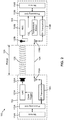
- FIG. 2 is a schematic diagram showing the determination of range between a reference device and a target device of the system of FIG. 1 ;
- FIGS. 3A and 3B show a flowchart illustrating the steps of measuring range between the reference device and target device
- FIG. 4 shows an example of determining the distance between the reference device and target device, and the possible locations of the target device
- FIG. 5A shows an example of determining the location of the target device from two reference devices and by using triangulation
- FIG. 5B shows an example of determining the location of the target device from two reference devices and by using triangulation, wherein the target device is collinear with the two reference devices;
- FIG. 6 shows an example of determining the location of the target device from three reference devices and by using triangulation
- FIG. 7A is a top view of a portion of the site of FIG. 1 , showing three reference devices at known three-dimensional (3D) locations and a target device;
- FIG. 7B is a side view of the site portion of FIG. 7A ;
- FIG. 7C is a perspective view of the site portion of FIG. 7A ;
- FIG. 8 is a schematic diagram showing the determination of range between a reference device and a target device of the system of FIG. 1 , according to an alternative embodiment
- FIG. 9 illustrates a ranging system of FIG. 1 in the form of a 3D input system, according to an alternative embodiment
- FIG. 10A is a bottom view of a position-sensing glove of the 3D input system of FIG. 9 ;
- FIG. 10B is a top view of the position-sensing glove of FIG. 10A .
- a ranging system is shown and is generally identified by the reference numeral 100 .
- the system 100 comprises one or more reference devices 102 and one or more target devices 104 deployed in a site 106 .
- the reference devices 102 in this embodiment transmit a wireless signal set 108
- the target devices 104 receive the wireless signal set 108 .
- the reference devices 102 communicate with target devices 104 via the wireless signal set 108 for determining the ranges of the target devices 104 .
- the range of an object refers to at least the distance between the object and a reference point, for example, a reference device.
- the one or more reference devices 102 are deployed at known locations of the site 106 , for example, a device specifically designed for the purposes described herein, a WI-FI® access point (WI-FI is a registered trademark of Wi-Fi Alliance, Austin, Tex., USA), a BLUETOOTH® access point (BLUETOOTH is a registered trademark of Bluetooth Sig. Inc., Kirkland, Wash., USA), and/or the like.
- WI-FI is a registered trademark of Wi-Fi Alliance, Austin, Tex., USA
- BLUETOOTH® access point BLUETOOTH is a registered trademark of Bluetooth Sig. Inc., Kirkland, Wash., USA
- each reference device 102 also comprises a speaker.
- the target devices 104 are associated with respective movable objects, such as humans, shopping carts, robots, a user's hands, and the like, moving within the site 106 .
- the target devices 104 may be any device having the functionality as described below and suitable for associating with movable objects, for example, signal-receiving devices specifically designed for the purposes described herein, smartphones such as Apple® iPhone® (Apple and iPhone are registered trademarks of Apple Inc., Cupertino, Calif., U.S.A.), Android® phones (Android is a trademark of Google LLC, Mountain View, Calif., U.S.A.), Windows phones (Windows is a registered trademark of Microsoft Corporation, Redmond, Wash., U.S.A.) and other smartphones, tablets such as Apple® iPad® (iPad is registered trademarks of Apple Inc., Cupertino, Calif., U.S.A.), Android® tablet, Microsoft® (Microsoft is a registered trademark of Microsoft Corporation, Redmond, Wash., U.S.A.)
- the wireless signal set 108 transmitted between a reference device 102 and a target device 104 comprises at least a first-type, high-speed wireless signal such as an RF signal, for example, a WI-FT® signal, a BLUETOOTH® signal, an Enhanced ShockBurst® (ShockBurst is a registered trademark of Nordic Semiconductor ASA, Trondheim NORWAY) signal or the like, and a second-type, low-speed wireless signal such as an acoustic signal.
- a first-type, high-speed wireless signal such as an RF signal, for example, a WI-FT® signal, a BLUETOOTH® signal, an Enhanced ShockBurst® (ShockBurst is a registered trademark of Nordic Semiconductor ASA, Trondheim NORWAY) signal or the like
- a second-type, low-speed wireless signal such as an acoustic signal.
- a reference device 102 may simultaneously communicate with one or more target devices 104
- a target device 104 may simultaneously communicate with one or more reference devices 102 .
- Suitable signal multiplexing technologies such as frequency-division multiplexing, time-division multiplexing, code-division multiplexing and the like, may be used for communication between one or more reference devices 102 and one or more target devices 104 .
- these signal multiplexing technologies are known in the art, and as new signal multiplexing technologies are equally applicable to the ranging system disclosed herein, the description in the following only uses one reference device 102 communicating with one target device 104 as an example for illustrating the invention.
- a reference device 102 comprises a processing unit 112 A coupled to and controlling, via a bus or individual circuitries (not shown), a memory component 114 A, and a set of signal transmitters including an RF transceiver 116 A, and an acoustic transmitter 120 A.
- the RF transceiver 116 A is coupled to an antenna 118 A for communicating with the target device 104 via a high-speed wireless signal such as an RF signal 124 .
- an RF transceiver is capable of transmitting and receiving an RF signal.
- the acoustic transmitter 120 A is coupled to a speaker 122 A for transmitting a low-speed wireless signal such as an acoustic signal 126 .
- the acoustic transmitter 120 A is a digital to analog converter (DAC), generating an analog signal to drive the speaker 122 A and to produce the low-speed wireless signal 126 .
- DAC digital to analog converter
- the reference device 102 may further comprise other suitable components and circuitry, depending on the implementation.
- the reference device 102 may comprise suitable signal-processing components and circuitry for processing the RF and/or acoustic signals for transmission.
- the reference device 102 may comprise suitable signal-processing components and circuitry for filtering the output of the DAC 120 A.
- the processing unit 112 A is also denoted as the transmitter logic layer.
- the RF transceiver 116 A, antenna 118 A, acoustic transmitter 120 A and speaker 122 A are collectively denoted as the transmitter physical layer.
- the target device 104 comprises a processing unit 112 B coupled to and controlling, via a bus or individual circuitries (not shown), a memory component 114 B, and a set of signal receivers including an RF transceiver 116 B, and an acoustic receiver 120 B.
- the RF transceiver 116 B is also coupled to an antenna 118 B for communicating with the reference device 102 via the RF (wireless) connection 124 (i.e., the RF signal 124 ; hereinafter the terms “RF signal” and “RF connection” may be also used interchangeably for simplicity).
- the acoustic receiver 120 B is also coupled to a microphone 122 B for receiving the acoustic signal transmitted from the reference device 102 .
- the acoustic receiver 120 B is an analog to digital converter (ADC), converting the output of the microphone 122 B to a digital signal for further processing.
- the target device 104 further comprises a temperature sensor 132 .
- the processing unit 112 B is also denoted as the receiver logic layer.
- the RF transceiver 116 B, antenna 118 B, acoustic receiver 120 B and microphone 122 B are collectively denoted as the receiver physical layer.
- each of the processing units 112 A and 112 B may be a specially designed controller chip using for example a programmed field-programmable gate array (FPGA), an application-specific integrated circuit (ASIC), and/or the like.
- each of the processing units 112 A and 112 B may be one or more single-core or multiple-core computing processors, such as Intel® microprocessors (Intel is a registered trademark of Intel Corporation, Santa Clara, Calif., U.S.A.), AMD microprocessors (AMD is a registered trademark of Advanced Micro Devices, Inc., Santa Clara, Calif., U.S.A.), ARM® microprocessors manufactured by a variety of manufactures under the ARM® architecture (ARM is a registered trademark of ARM Ltd., Cambridge, UK), AVR® microcontrollers (AVR and Atmel are registered trademarks of Atmel corporation, San Jose, Calif., USA), and/or the like.
- Each of the memory components 114 A and 114 B may be RAM, ROM, EEPROM, solid
- the reference device 102 and the target device 104 use an RF signal 124 and an acoustic signal 126 for measurement of the range 128 therebetween.
- the reference device 102 and the target device 104 also use the RF connection 124 for other communication purposes, such as sending and receiving commands and data to/from each other.
- the RF connection 124 shown in FIG. 2 is used for range measuring only, and the reference device 102 and the target device 104 do not communicate with each other for other purposes.
- the reference device 102 and the target device 104 use a different wireless means, e.g., a different wireless channel, a different wireless communication technology, for communicating with each other for other purposes such as sending and receiving commands and data to/from each other.
- a different wireless means e.g., a different wireless channel, a different wireless communication technology
- the reference device 102 and the target device 104 use a an Enhanced ShockBurstTM signal as the RF signal 124 for range measuring, and use a BLUETOOTH® connection for sending and receiving commands and data to/from each other.
- FIG. 3A is a flowchart showing the steps of measuring range between the reference device 102 and target device 104 .
- a range measurement may be initiated by an initiator from the reference device side (step 202 ), or from the target device side (step 204 ).
- the initiator may be a user who manually initiates the range measurement by, for example, pressing a button on the reference device 102 or on the target device 104 .
- the initiator may be a computer program or service, which automatically initiates the range measurement as needed or periodically at predefined time intervals.
- the computer program or service may be a program or service running in the reference device 102 or the target device 104 , or may be a program or service running in an external device in communication with the reference device 102 or the target device 104 .
- a user-launched map or navigation program running on the target device 104 may automatically and periodically request range measurement for updating the position of the target device 104 .
- an external service such as a shopping cart tracking service running on an external server may communicate with one or more reference devices 102 , requesting range measurement of the target devices 102 installed on shopping carts to continuously track the shopping carts in the site 106 .
- the computer program or service may comprise software code stored in a content-erasable memory such as a hard drive, a solid-state memory, and/or the like.
- the computer program or service may comprise firmware code stored in a ROM, an EPROM (the content of which may be erasable using a special programming method), and/or the like.
- the reference device 102 initiates the range measurement process at step 210 .
- the target device 104 sends the request to the reference device 102 , requesting the reference device 102 to begin the range measurement process (step 208 ).
- the reference device 102 initiates the range measurement process (step 210 ).
- the reference device 102 After initiating range measurement, the reference device 102 transmits an RF signal 124 and an acoustic signal 126 to the target device 104 , respectively, via the RF transceiver 116 A through the antenna 118 A, and via the acoustic transmitter 120 A through the speaker 122 A (steps 212 and 214 , respectively).
- the low-speed acoustic signal 126 at the transmitter side is encoded with a binary codeword of length L P , denoted by P AC [n], and then modulated to a ultrasonic frequency for transmission.
- the received acoustic signal is demodulated and then decoded for further processing.
- either, both, or neither of the RF and acoustic signals 124 and 126 may be encoded using a suitable coding scheme.
- a variety of binary/M-ary coding schemes may be used for encoding the RF signal 124 and/or the acoustic signal 126 . Coding is commonly used in positioning for improved time of arrival estimation, error detection, error correction, interference combatting and/or the like.
- Codeword modulation (inclusion) may be done using a variety of modulation methods e.g. on-off keying (OOK), audio frequency shift keying (AFSK), Binary Frequency Shift Keying (BFSK), Amplitude Shift Keying (ASK), Continuous Phase Frequency Shift Keying (CPFSK), or the like.
- OOK on-off keying
- AFSK audio frequency shift keying
- BFSK Binary Frequency Shift Keying
- ASK Amplitude Shift Keying
- CPFSK Continuous Phase Frequency Shift Keying
- the high-speed, RF signal 124 and the low-speed, acoustic signal 126 are transmitted substantially simultaneously.
- the RF and acoustic signals 124 and 126 propagate through their respective media.
- the speed of the RF signal 124 in air is approximately the speed of light, which is about 2.99 ⁇ 10 8 meters per second (m/s) in free space.
- the speed of the acoustic signal 126 is the speed of sound, which is approximately 343.4 m/s in air at 20° C.
- the target device 104 receives the RF signal 124 via the antenna 118 B and the RF transceiver 116 B, and stores the received RF signal and the time-of-arrival t RF of the received RF signal 124 , in the memory component 114 B (step 218 ).
- the target device 104 uses the temperature sensor 132 (see FIG. 2 ) to measure the ambient air temperature T S (step 220 ), and calculates a localized acoustic signal speed ⁇ AC as ⁇ AC ⁇ 331.4+0.6 T S , (2) where T S is in degrees Celsius.
- T S is in degrees Celsius.
- the localized acoustic signal speed ⁇ AC may be calculated with multiple measurements over time, filtered, and/or by using other known methods, such as Newton-Laplace equations, and the like.
- the target device 104 starts to receive the acoustic signal 126 from the microphone 122 B, storing the samples and the sampling starting time in memory 114 B (step 224 ).
- receiving the acoustic signal 126 is conducted by sampling the output of the microphone 122 B via the analog-to-digital converter 120 B.
- the acoustic signal 126 represented in the discrete time domain and herein denoted as S A [n]
- the time at which the sampling of the acoustic signal began i.e., the starting time t SA of step 222 , are stored in the memory component 114 B (step 224 ).
- the acoustic signal sampling is stopped, and the process enters step 226 .
- the acoustic signal 126 and therefore the discrete-time acoustic signal S A [n], comprises the codeword P AC [n].
- t max (d max / ⁇ AC )+ ⁇ , although a more accurate equation that derives from (10) may also be used.
- ⁇ SA and t WIN may be determined from previous determined distances.
- t AC is the time of arrival of the received acoustic signal 126 .
- the time-of-arrival of each signal 124 , 126 is determined using suitable signal processing methods depending on the implementation. For example, FIG. 3B illustrates an example of the detailed steps for calculating the time difference ⁇ t in discrete-time domain.
- a bandpass filter (BPF) is applied to the received acoustic signal S A [n] for noise reduction, generating a filtered acoustic signal S F [n].
- the received acoustic signal S A [n] generally comprises noise, and may be distorted, for example, may exhibit a frequency shift from the transmitted acoustic signal.
- the BPF bandwidth is set to be wider than the acoustic signal bandwidth to account for sources of frequency shift, such as oscillator offset between the target device 104 and the reference device 102 , Doppler shift due to relative motion, and the like.
- the acoustic signal is first sampled, and then the sampled acoustic signal is bandpass filtered
- the acoustic signal may first be bandpass filtered, and the filtered acoustic signal is sampled to obtain the filtered acoustic signal S F [n].
- bandpass filtering may be omitted.
- the acoustic signal S F [n] is demodulated at step 254 .
- the demodulation process varies depending on the implementation and may include frequency estimation (e.g. using FFT or other frequency estimation methods), down conversion, filtering (e.g. low-pass filtering), and the like.
- the outcome of signal demodulation at step 253 is a demodulated signal S d [n], which in this embodiment contains the codeword P AC [n].
- a local replica signal S L [n] is generated at the target device 104 , having the same codeword, P AC [n] as the acoustic signal 126 at the transmitter side before modulation.
- the local replica signal S L [n] is generated such that it also accounts for the estimated oscillator offset between the reference device 102 and the target device 104 , and/or other sources of frequency shift, e.g. Doppler shift, and the like, by scaling the sample-rate at which the local signal is generated.
- the local replica signal S L [n] is cross-correlated with the demodulated signal S d [n] as follows:
- the offset n 0 between the local replica signal S L [n] and the demodulated acoustic signal S d [n] is estimated using suitable time of arrival estimation methods. For example, in this embodiment, a Maximum Likelihood estimator is used to estimate the offset n 0 as:
- n 0 thus represents the offset in samples between S L [n] and S d [n].
- the time difference ⁇ t between the time-of-arrivals t RF and t AC in the continuous-time domain is:
- interpolation methods may be used to improve the estimation accuracy of t AC .
- the standard parabolic interpolation method is given below, however other methods are known and may be used, such as the early-late method.
- the target device 104 calculates the range or distance d between the reference device 102 and the target device 104 as:
- the calculated range d is further processed (step 230 ). For example, if the target device 104 is not the initiator of the measurement, then the calculated range d may be reported to the initiator. As another example, in alternative embodiments where the target device 104 is not the initiator of the measurement, then it may report one or more of the measured/calculated/estimated parameters e.g., ⁇ t, t AC , the calculated range d, and/or other relevant parameters, to the initiator.
- the measured/calculated/estimated parameters e.g., ⁇ t, t AC , the calculated range d, and/or other relevant parameters
- some of the target devices 104 are equipped with other ancillary sensors e.g. accelerometer, gyroscope, infrared sensor, and/or the like.
- ancillary sensor(s) provide(s) additional information about other environmental parameters and/or about the state of the device, e.g., its orientation, which may be deemed useful for some applications such as virtual reality for example.
- the reference device 102 and the target device 104 are substantially at the same elevation. Then, as shown in FIG. 4 , after calculation of d, it is determined that the target device 104 is located at a point on the circle 282 centered at the reference device 102 and having a radius of about d. As the reference device 102 is at a known location in the site 106 , the location of the target device 104 is then somewhere along the circle perimeter 282 . In some embodiments that the accurate location of the target device 104 is not required, determining the location of the target device 104 to be somewhere along the perimeter of a calculated circle may be sufficient.
- the range measurement shown in FIGS. 3A and 3B is conducted for determining the distance between the target device 104 and each of two reference devices 102 A and 102 B, wherein the distance D between reference devices 102 A and 102 B is known.
- the distance between the reference device 102 A and the target device 104 is d 1
- the distance between the reference device 102 B and the target device 104 is d 2 .
- the reference devices 102 A and 102 B and the target device 104 are substantially at the same elevation.
- the location of the target device 104 may be determined using well-known triangulation at any one of the two locations 104 - 1 and 104 - 2 . In some embodiments that the accurate location of the target device 104 is not required, determining the location of the target device 104 to be at one of two possible locations may be sufficient.
- the position of the target device 104 may be determined as a one-dimensional (1D) position along the line of the two reference devices 102 based on the determined distances between the target device 104 and the two reference devices 102 .
- the system may use other suitable information to refine the location of the target device. For example, if the system knows that the target device 104 can only be located on one side of the line connecting the reference devices 102 A and 102 B, for example, the other side is an area or room inaccessible to the target device 104 , then, the system can further refine the location of the target device 104 to be one of the locations 104 - 1 and 104 - 2 that is accessible thereto.
- three reference devices 102 A, 102 B and 102 C may be used for determining the location of a target device 104 to be within the area 104 - 3 , after calculating the distances d 1 , d 2 , and d 3 between the target device 104 and the reference devices 102 A, 102 B and 102 C, respectively.
- the system assumes that the target device 104 and the three reference devices 102 A, 102 B and 102 C are at the same elevation.
- the system does not consider that the target device 104 and reference devices 102 are at the same elevation.
- FIGS. 7A to 7C show three reference devices 102 A, 102 B and 102 C at the same elevation 302 , and a target device 104 not necessarily at the same elevation as the reference device 102 A to 102 C.
- the distances r 0 between reference devices 102 A and 102 B, r 1 between reference devices 102 A and 102 C and r 2 between reference devices 102 B and 102 C, are known.
- the location of the reference device 102 C, (x c , y c , z c ), relative to this coordinate system may be calculated from the well-known trilateration equations as:
- the distances u 0 , u 1 and u 2 between the target device 104 and, respectively, the reference devices 102 A, 102 B and 102 C are determined. Then, using the well-known trilateration equations, the location of the target device 104 relative to the coordinate system defined earlier target device may be calculated as:
- the location of the target device 104 may be at (x m , y m , z m + ), or at (x m , y m , z m ⁇ ).
- determining the location of the target device 104 to be at any one of two possible locations may be sufficient. In some embodiments, determining the target device 104 is at any one of two possible locations may be sufficient for relative positioning thereafter.
- the system may further use other suitable information to refine the location of the target device 104 . For example, if the location (x m , y m , Z m ⁇ ) is inaccessible to the target device, or if the system knows that the references devices are on a floor of a room, and the target device 104 is on or above the floor 302 , the system then determines that the location of the target device is at (x m , y m , z m + ). Alternatively, the system may use more than three non-coplanar reference devices 102 to more accurately determine the location of the target device 104 .
- the location of the target device calculated using trilateration, or more generally, multilateration may be ambiguous, and the system may further use other suitable information, e.g., the area accessibility or inaccessibility of the target device 104 to eliminate unlikely locations and solve the ambiguity.
- a Least Squares method may be used to calculate the 3D coordinates (x m , y m , z m ) of the target device 104 in the 3D space using the known positions (x 1 , y 1 , z 1 ), (x 2 , y 2 , z 2 ), . . . (x N , y N , z N ) of four or more reference devices 102 , relative to an arbitrary but otherwise known coordinate system.
- the location of the target device 104 relative to the reference devices with respect to the defined coordinate system can be expressed as:
- A [ - 2 ⁇ x 1 - 2 ⁇ y 1 - 2 ⁇ z 1 1 - 2 ⁇ x 2 - 2 ⁇ y 2 - 2 ⁇ z 2 1 ⁇ ⁇ ⁇ ⁇ - 2 ⁇ x N - 2 ⁇ y N - 2 ⁇ z N 1 ]
- b [ R 1 - x 1 2 - y 1 2 - z 1 2 ⁇ R N - x N 2 - y N 2 - z N 2 ] .
- the positions of all or a subset of the reference devices 102 may be surveyed during calibration.
- the latency comprises audio latency, i.e., the latency of the audio signal 126 , and RF signal latency, i.e., the latency of the RF signal 124 .
- the audio latency in the reference device 102 refers to the delay or time difference from the time that the processing unit 112 A signals the digital to analog converter 120 A to transmit the audio signal 126 , to the time that the audio signal 126 has actually been transmitted from the speaker 122 A.
- the RF signal latency in the reference device 102 refers to the delay from the time that the processing unit 112 A signals the RF transceiver 116 A to transmit the RF signal 124 , to the start of transmission of the RF signal 124 from the antenna 118 A.
- the audio latency in the target device 104 refers to the delay from the time that the audio signal 126 is received by the microphone 122 B, and the time that the received audio signal 126 has been received by the processing unit 112 B for processing.
- the RF signal latency in the target device 104 refers to the delay from the time that the RF signal 124 is received at the antenna 118 B, and the time that the received RF signal 124 has been time-tagged by the transceiver.
- the overall latency is considered small and hence ignored. However, in these embodiments, the accuracy of the calculated distance, and consequently the accuracy of the calculated target device location may be reduced.
- the system estimates the overall latency using a calibration process to improve the range finding and/or object positioning accuracy.
- ⁇ ENC an arbitrary but known delay ⁇ ENC is introduced in the transmission of the acoustic signal 124 , for example, for privacy/security purposes. Therefore, calculation of the correct range requires specific knowledge of the additional term ⁇ ENC .
- ⁇ ENC may be generated from a pre-shared key such as with a hash-based message authentication codes (HMAC) based one-time password (HOTP) algorithm, time-based one-time password (TOTP) algorithm or the like, or pre-generated by a central server, or generated randomly and communicated to the receiver using public key cryptographic methods, such as the Rivest-Shamir-Adleman (RSA) method or the like.
- HMAC hash-based message authentication codes
- TOTP time-based one-time password
- some reference devices 102 may each comprise an RF signal transmitter rather than an RF transceiver. These reference devices 102 therefore can only act as signal transmitters.
- some target devices 104 may each comprise an RF signal receiver rather than an RF transceiver. These target devices 104 therefore can only receive RF signals.
- some reference devices 102 may each comprise a temperature sensor 132 A.
- the speed of sound is also calculated at the reference devices 102 , and an averaged speed of sound is calculated by averaging the calculated speeds of sound at both the reference devices 102 and the target device 104 for improved accuracy.
- the high-speed wireless signal 124 is an optical signal.
- a disadvantage of the system in this embodiment is that obstacles may block the optical signal path, therefore hindering the range estimation.
- temperature sensor is used for calibrating the speed of sound.
- other known methods may be used to measure the local speed of sound or the ambient temperature.
- neither the target device 104 nor the reference device 102 contains a temperature sensor.
- an approximate predefined value may be used. Those skilled in the art appreciate that ranging errors may result from such approximation.
- the high-speed, RF signal 124 and the low-speed, acoustic signal 126 are transmitted substantially simultaneously or within a time interval as small as possible.
- one of the RF signal 124 and the acoustic signal 126 is transmitted at a different time instant after the transmission of the other thereof, with a predefined time delay that is known to the initiating device.
- the reference devices 102 transmit the wireless signal set 108 , and the target devices receive the wireless signal set 108 .
- the target devices 104 may transmit the wireless signal set 108
- the reference devices 102 may receive the wireless signal set 108 .
- the positioning system 100 may be part of a virtual reality (VR) system and/or augmented reality (AR) system.
- VR virtual reality
- AR augmented reality
- the virtual reality (VR) system is a three-dimensional (3D) input system.
- the 3D input system 100 comprises a computing device (not shown) such as a tablet, smartphone, laptop computer, desktop computer, or the like, one or more wearable devices such as gloves 500 each coupled with a target device 104 (see FIGS. 10A and 10B ), and a plurality of reference devices 102 at known locations.
- the computing device is in communication with the gloves 500 and the reference devices 102 using a suitable wireless connection, e.g. ANTTM (ANT is a trademark of ANT Wireless, Cochrane, Alberta, Canada), BLUETOOTH®, or the like, enabling a variety of user inputs, e.g. various gestures or commands.
- ANTTM ANT is a trademark of ANT Wireless, Cochrane, Alberta, Canada
- BLUETOOTH® or the like
- WIFI® Wireless Fidelity
- ZIGBEE ZigBee Alliance Corp., San Ramon, Calif., USA
- Ethernet USB
- Optical connection serial cable, parallel cable, or the like, may alternatively be used for functionally connecting the computing device, the gloves 500 and the reference devices 102 .
- FIGS. 10A and 10B show the bottom (palm) and top (back) views of a right-hand position-sensing glove 500 , respectively.
- a left-hand position-sensing glove is similar to that of FIGS. 15A and 15B but with a generally mirrored configuration.
- the glove 500 is made of lightweight fabrics and mesh so as to minimize hindering the user's dexterity. As shown, the glove 500 comprises five finger portions 504 to 512 and a wrist portion 514 , corresponding to the five fingers and the wrist of the user's hand.
- a plurality of angle encoders 520 are installed on the top side of the glove 500 at the positions corresponding to the joints of human fingers (i.e., on the joints of the entire finger from the fingertip to the knuckle of the finger joining the hand) for detecting the angle of the respective joint.
- An angle encoders 522 is also installed on the glove 500 at the wrist position 514 for detecting the angle of the wrist.
- a target device 104 is affixed to the glove 500 to provide ranging information of the glove 500 relative to one or more reference devices 102 . The ranging information may then be fused with the measured angles detected by the angle encoders on the glove 500 to interpret a variety of user inputs such as hand gesture or commands in a 3D space.
- the 3D input system 100 and the position-sensing glove 500 are similar to those described in US Patent Publication No. US 2016/0132111 A1, published on May 12, 2016 and assigned to the Applicant of the subject application, the content of which is incorporated herein by reference in its entirety.
- the position of each fingertip in the 3D space may be determined. Gestures and/or commands can then be determined based on the obtained positions.
- VR equipment may also comprise one or more target devices 104 for determining the range/position thereof in a 3D space.
- a head-mounted display may comprise a target device 104 affixed thereto for range estimation or relative position estimation within the virtual environment.
- references devices may be transmitter devices and other references devices may be receiver devices.
- target devices may be receiver devices and other target devices may be transmitter devices.
Landscapes
- Engineering & Computer Science (AREA)
- Physics & Mathematics (AREA)
- General Physics & Mathematics (AREA)
- Radar, Positioning & Navigation (AREA)
- Remote Sensing (AREA)
- Computer Networks & Wireless Communication (AREA)
- Signal Processing (AREA)
- Artificial Intelligence (AREA)
- Measurement Of Velocity Or Position Using Acoustic Or Ultrasonic Waves (AREA)
- Radar Systems Or Details Thereof (AREA)
- Automatic Focus Adjustment (AREA)
- Measurement Of Optical Distance (AREA)
Abstract
Description
wherein d is the distance between the apparatus and said location, Δt is the time difference between the time of receiving the first-speed signal transmitted from said location and the time of receiving the second-speed signal transmitted from said location, c1 is the first speed, c2 is the second speed, and c1>c2.
νAC≈331.4+0.6T S, (2)
where TS is in degrees Celsius. Of course, in various embodiments, the localized acoustic signal speed νAC may be calculated with multiple measurements over time, filtered, and/or by using other known methods, such as Newton-Laplace equations, and the like.
d max=νAC(τSA +t WIN), (3)
d min=τSAνAC (4)
where N is the total number of samples in the signal Sd[n]. Then, at
where FS is the sampling rate (in samples per second) of the analog-to-
where νRF=2.99×10⁸ m/s is the RF signal speed, νAC is the localized acoustic signal speed calculated using Equation (2), and Δt is calculated using Equation (8).
Therefore, the location of the
R n=(X m −x n)2+(y m −y n)2+(Z m −Z n)2 (18)
for n=1, 2, . . . , N.
where (⋅)T represents matrix transpose, (⋅)−1 represents matrix inverse,
Claims (20)
Priority Applications (2)
| Application Number | Priority Date | Filing Date | Title |
|---|---|---|---|
| US16/919,822 US10893502B2 (en) | 2016-01-20 | 2020-07-02 | Range-finding and object-positioning systems and methods using same |
| US17/145,904 US11438867B2 (en) | 2016-01-20 | 2021-01-11 | Range-finding and object-positioning systems and methods using same |
Applications Claiming Priority (5)
| Application Number | Priority Date | Filing Date | Title |
|---|---|---|---|
| US201662280958P | 2016-01-20 | 2016-01-20 | |
| US15/411,935 US10051599B2 (en) | 2016-01-20 | 2017-01-20 | Range-finding and object-positioning systems and methods using same |
| US16/031,553 US10448357B2 (en) | 2016-01-20 | 2018-07-10 | Range-finding and object-positioning systems and methods using same |
| US16/560,543 US10736075B2 (en) | 2016-01-20 | 2019-09-04 | Range-finding and object-positioning systems and methods using same |
| US16/919,822 US10893502B2 (en) | 2016-01-20 | 2020-07-02 | Range-finding and object-positioning systems and methods using same |
Related Parent Applications (1)
| Application Number | Title | Priority Date | Filing Date |
|---|---|---|---|
| US16/560,543 Continuation US10736075B2 (en) | 2016-01-20 | 2019-09-04 | Range-finding and object-positioning systems and methods using same |
Related Child Applications (1)
| Application Number | Title | Priority Date | Filing Date |
|---|---|---|---|
| US17/145,904 Continuation US11438867B2 (en) | 2016-01-20 | 2021-01-11 | Range-finding and object-positioning systems and methods using same |
Publications (2)
| Publication Number | Publication Date |
|---|---|
| US20200344716A1 US20200344716A1 (en) | 2020-10-29 |
| US10893502B2 true US10893502B2 (en) | 2021-01-12 |
Family
ID=59314906
Family Applications (5)
| Application Number | Title | Priority Date | Filing Date |
|---|---|---|---|
| US15/411,935 Active US10051599B2 (en) | 2016-01-20 | 2017-01-20 | Range-finding and object-positioning systems and methods using same |
| US16/031,553 Active US10448357B2 (en) | 2016-01-20 | 2018-07-10 | Range-finding and object-positioning systems and methods using same |
| US16/560,543 Active US10736075B2 (en) | 2016-01-20 | 2019-09-04 | Range-finding and object-positioning systems and methods using same |
| US16/919,822 Active US10893502B2 (en) | 2016-01-20 | 2020-07-02 | Range-finding and object-positioning systems and methods using same |
| US17/145,904 Active US11438867B2 (en) | 2016-01-20 | 2021-01-11 | Range-finding and object-positioning systems and methods using same |
Family Applications Before (3)
| Application Number | Title | Priority Date | Filing Date |
|---|---|---|---|
| US15/411,935 Active US10051599B2 (en) | 2016-01-20 | 2017-01-20 | Range-finding and object-positioning systems and methods using same |
| US16/031,553 Active US10448357B2 (en) | 2016-01-20 | 2018-07-10 | Range-finding and object-positioning systems and methods using same |
| US16/560,543 Active US10736075B2 (en) | 2016-01-20 | 2019-09-04 | Range-finding and object-positioning systems and methods using same |
Family Applications After (1)
| Application Number | Title | Priority Date | Filing Date |
|---|---|---|---|
| US17/145,904 Active US11438867B2 (en) | 2016-01-20 | 2021-01-11 | Range-finding and object-positioning systems and methods using same |
Country Status (7)
| Country | Link |
|---|---|
| US (5) | US10051599B2 (en) |
| EP (2) | EP3405809A4 (en) |
| JP (2) | JP2019506604A (en) |
| KR (1) | KR102252251B1 (en) |
| CN (1) | CN109073740B (en) |
| CA (3) | CA3011922C (en) |
| WO (1) | WO2017124195A1 (en) |
Families Citing this family (14)
| Publication number | Priority date | Publication date | Assignee | Title |
|---|---|---|---|---|
| CN109073740B (en) * | 2016-01-20 | 2019-09-10 | 杰洛基有限公司 | Ranging and object positioning system and its application method |
| US11134864B2 (en) * | 2016-07-13 | 2021-10-05 | Alexei L. Vyssotski | Tracking method and system for small animal research |
| US10986435B2 (en) * | 2017-04-18 | 2021-04-20 | Massachusetts Institute Of Technology | Electrostatic acoustic transducer utilized in a hearing aid or audio processing system |
| US10078135B1 (en) * | 2017-04-25 | 2018-09-18 | Intel Corporation | Identifying a physical distance using audio channels |
| US10319228B2 (en) | 2017-06-27 | 2019-06-11 | Waymo Llc | Detecting and responding to sirens |
| KR102096531B1 (en) * | 2018-06-05 | 2020-04-02 | 국방과학연구소 | Transmission and receiving method and apparatus for distance and doppler estimation of a target |
| KR102257994B1 (en) * | 2019-09-02 | 2021-05-31 | 삼성전자주식회사 | Method and apparatus for determining proximity |
| US11229002B2 (en) * | 2019-09-05 | 2022-01-18 | Apple Inc. | Ranging with a mobile cellular device |
| JP2023518215A (en) * | 2020-03-12 | 2023-04-28 | ゼロキー インコーポレイテッド | Ultra-precision object positioning system and self-localization method using the same |
| JP7345190B2 (en) * | 2020-05-25 | 2023-09-15 | 株式会社井上政商店 | Compost raw material temperature control device, composting processing facility, compost raw material management thermometer, and compost raw material temperature control method |
| FR3119026B1 (en) * | 2021-01-18 | 2022-12-09 | Psa Automobiles Sa | CONTROL OF THE MOVEMENT OF A MOBILE BOX TOWARDS AN OBJECT BY ANALYSIS OF RADIO AND ACOUSTIC SIGNALS |
| EP4084349A1 (en) | 2021-04-30 | 2022-11-02 | Hahn-Schickard-Gesellschaft für angewandte Forschung e.V. | Combined beamforming of electromagnetic and acoustic waves |
| US20240017342A1 (en) | 2022-07-18 | 2024-01-18 | Illinois Tool Works Inc. | Welding technique monitoring systems using acoustic tracking |
| NO20221247A1 (en) * | 2022-11-18 | 2024-05-20 | Elliptic Laboratories Asa | Device ranging |
Citations (4)
| Publication number | Priority date | Publication date | Assignee | Title |
|---|---|---|---|---|
| US6999545B2 (en) * | 2001-10-26 | 2006-02-14 | Microsoft Corporation | Method and system for undersampled symbol synchronization |
| US20150247916A1 (en) * | 2014-03-03 | 2015-09-03 | Rosemount Inc. | Indoor positioning system |
| US20160202343A1 (en) * | 2015-01-09 | 2016-07-14 | Fujitsu Limited | Location information determination system |
| US10051599B2 (en) * | 2016-01-20 | 2018-08-14 | Zerokey Inc. | Range-finding and object-positioning systems and methods using same |
Family Cites Families (24)
| Publication number | Priority date | Publication date | Assignee | Title |
|---|---|---|---|---|
| US4747064A (en) * | 1984-03-19 | 1988-05-24 | Johnston Robert D | Approaching vehicle informing system and method |
| JPS63266377A (en) * | 1987-04-24 | 1988-11-02 | Kozo Yamamoto | Acoustic wave surveying system |
| JPH04322210A (en) * | 1991-04-22 | 1992-11-12 | Olympus Optical Co Ltd | Range finder |
| JPH05297117A (en) * | 1992-04-21 | 1993-11-12 | Taitetsuku:Kk | Position sensing display system |
| JPH08189823A (en) * | 1995-01-06 | 1996-07-23 | Nanno Kensetsu Kk | Distance measuring apparatus for tunnel by sound wave |
| EP0962908B1 (en) * | 1998-06-05 | 2005-09-28 | Honda Giken Kogyo Kabushiki Kaisha | Movable body detecting/notifying system |
| JP2001066360A (en) * | 1999-08-26 | 2001-03-16 | Sharp Corp | Distance detection system |
| ATE338301T1 (en) * | 2002-04-15 | 2006-09-15 | Epos Technologies Ltd | METHOD AND SYSTEM FOR COLLECTING POSITIONAL DATA |
| KR100565227B1 (en) * | 2003-12-22 | 2006-03-30 | 엘지전자 주식회사 | Position recognition apparatus and method for mobile robot |
| US20070205886A1 (en) * | 2006-03-01 | 2007-09-06 | Huseth Steve D | RF/acoustic person locator system |
| JP2007322433A (en) * | 2006-06-05 | 2007-12-13 | Samsung Electronics Co Ltd | Position estimation method and device of mobile robot |
| JP2009052948A (en) * | 2007-08-24 | 2009-03-12 | Fujitsu Ltd | Position measuring method |
| JP2009210407A (en) * | 2008-03-04 | 2009-09-17 | Mitsubishi Electric Corp | Positioning apparatus and position estimation method |
| CN101592727B (en) * | 2008-05-29 | 2013-05-01 | 日电(中国)有限公司 | Autonomous indoor ultrasonic locating system, device and method |
| KR20100073604A (en) * | 2008-12-23 | 2010-07-01 | 주식회사 나인티시스템 | Apparatus and method for estimating position of mobile unit |
| JP2013124939A (en) * | 2011-12-15 | 2013-06-24 | Mitsubishi Heavy Ind Ltd | Position measuring system and position measuring method |
| US20130172907A1 (en) * | 2012-01-02 | 2013-07-04 | Bernard Michael HARRIS | System and method for spatial location and tracking |
| JP6074233B2 (en) * | 2012-11-15 | 2017-02-01 | 古河ユニック株式会社 | Boom automatic follower for work equipment |
| JP2014106029A (en) * | 2012-11-26 | 2014-06-09 | Mitsubishi Heavy Ind Ltd | System and method for inspecting wall thickness of boiler tube |
| WO2014102931A1 (en) * | 2012-12-26 | 2014-07-03 | 株式会社安川電機 | Positioning system, mobile station, and base station |
| JP6417749B2 (en) * | 2014-06-26 | 2018-11-07 | 日本電気株式会社 | Measuring device, measuring system, program, and control method |
| WO2016074087A2 (en) | 2014-11-11 | 2016-05-19 | Helio Technology Inc. | A method of detecting user input in a 3d space and a 3d input system employing same |
| CN204228953U (en) * | 2014-12-15 | 2015-03-25 | 华南理工大学建筑设计研究院 | A kind of measuring system determining locus, buildings monitoring point |
| CN105005022A (en) * | 2015-06-19 | 2015-10-28 | 上海美迪索科电子科技有限公司 | Multimode indoor positioning method and device based on radio frequency and ultrasonic wave |
-
2017
- 2017-01-20 CN CN201780018631.8A patent/CN109073740B/en active Active
- 2017-01-20 JP JP2018538715A patent/JP2019506604A/en active Pending
- 2017-01-20 KR KR1020187023900A patent/KR102252251B1/en active IP Right Grant
- 2017-01-20 CA CA3011922A patent/CA3011922C/en active Active
- 2017-01-20 US US15/411,935 patent/US10051599B2/en active Active
- 2017-01-20 CA CA3205009A patent/CA3205009A1/en active Pending
- 2017-01-20 CA CA3205004A patent/CA3205004A1/en active Pending
- 2017-01-20 EP EP17740942.2A patent/EP3405809A4/en not_active Ceased
- 2017-01-20 EP EP24163809.7A patent/EP4394428A2/en active Pending
- 2017-01-20 WO PCT/CA2017/050066 patent/WO2017124195A1/en active Application Filing
-
2018
- 2018-07-10 US US16/031,553 patent/US10448357B2/en active Active
-
2019
- 2019-09-04 US US16/560,543 patent/US10736075B2/en active Active
-
2020
- 2020-07-02 US US16/919,822 patent/US10893502B2/en active Active
-
2021
- 2021-01-11 US US17/145,904 patent/US11438867B2/en active Active
-
2023
- 2023-03-10 JP JP2023037641A patent/JP2023072008A/en active Pending
Patent Citations (6)
| Publication number | Priority date | Publication date | Assignee | Title |
|---|---|---|---|---|
| US6999545B2 (en) * | 2001-10-26 | 2006-02-14 | Microsoft Corporation | Method and system for undersampled symbol synchronization |
| US20150247916A1 (en) * | 2014-03-03 | 2015-09-03 | Rosemount Inc. | Indoor positioning system |
| US20160202343A1 (en) * | 2015-01-09 | 2016-07-14 | Fujitsu Limited | Location information determination system |
| US10051599B2 (en) * | 2016-01-20 | 2018-08-14 | Zerokey Inc. | Range-finding and object-positioning systems and methods using same |
| US10448357B2 (en) * | 2016-01-20 | 2019-10-15 | Zerokey Inc. | Range-finding and object-positioning systems and methods using same |
| US10736075B2 (en) * | 2016-01-20 | 2020-08-04 | Zerokey Inc. | Range-finding and object-positioning systems and methods using same |
Also Published As
| Publication number | Publication date |
|---|---|
| KR20180114059A (en) | 2018-10-17 |
| CN109073740B (en) | 2019-09-10 |
| US20210235411A1 (en) | 2021-07-29 |
| EP4394428A2 (en) | 2024-07-03 |
| CA3011922A1 (en) | 2017-07-27 |
| JP2023072008A (en) | 2023-05-23 |
| US10736075B2 (en) | 2020-08-04 |
| CA3011922C (en) | 2024-06-18 |
| EP3405809A1 (en) | 2018-11-28 |
| US20180324745A1 (en) | 2018-11-08 |
| US11438867B2 (en) | 2022-09-06 |
| US20200344716A1 (en) | 2020-10-29 |
| CA3205009A1 (en) | 2017-07-27 |
| JP2019506604A (en) | 2019-03-07 |
| EP3405809A4 (en) | 2019-09-04 |
| KR102252251B1 (en) | 2021-05-14 |
| US10448357B2 (en) | 2019-10-15 |
| US10051599B2 (en) | 2018-08-14 |
| WO2017124195A1 (en) | 2017-07-27 |
| US20200145957A1 (en) | 2020-05-07 |
| CN109073740A (en) | 2018-12-21 |
| US20170208565A1 (en) | 2017-07-20 |
| CA3205004A1 (en) | 2017-07-27 |
Similar Documents
| Publication | Publication Date | Title |
|---|---|---|
| US10893502B2 (en) | Range-finding and object-positioning systems and methods using same | |
| Mao et al. | CAT: High-precision acoustic motion tracking | |
| Liu et al. | Indoor acoustic localization: A survey | |
| CN108693502B (en) | Method and system for determining a position of a user device relative to a vehicle | |
| JP6698029B2 (en) | Indoor positioning system | |
| US10182414B2 (en) | Accurately tracking a mobile device to effectively enable mobile device to control another device | |
| US20090149202A1 (en) | System and method for determination of position | |
| KR20090003365A (en) | Wireless localization apparatus and method | |
| EP3142400A1 (en) | Pairing upon acoustic selection | |
| US20180128897A1 (en) | System and method for tracking the position of an object | |
| CN112098943A (en) | Positioning method of wearable device and intelligent device | |
| US10856108B2 (en) | System and method of locating a radio frequency (RF) tracking device using a calibration routine | |
| EP4022337B1 (en) | Position determination | |
| Zheng | Acoustic motion tracking and its application | |
| KR20220082856A (en) | Frequency Shift Determination |
Legal Events
| Date | Code | Title | Description |
|---|---|---|---|
| AS | Assignment |
Owner name: ZEROKEY INC., CANADA Free format text: NUNC PRO TUNC ASSIGNMENT;ASSIGNORS:LOWE, MATTHEW WILLIAM;DEHGHANIAN, VAHID;REEL/FRAME:053110/0673 Effective date: 20170609 |
|
| FEPP | Fee payment procedure |
Free format text: ENTITY STATUS SET TO UNDISCOUNTED (ORIGINAL EVENT CODE: BIG.); ENTITY STATUS OF PATENT OWNER: SMALL ENTITY |
|
| FEPP | Fee payment procedure |
Free format text: ENTITY STATUS SET TO SMALL (ORIGINAL EVENT CODE: SMAL); ENTITY STATUS OF PATENT OWNER: SMALL ENTITY |
|
| STPP | Information on status: patent application and granting procedure in general |
Free format text: PUBLICATIONS -- ISSUE FEE PAYMENT VERIFIED |
|
| STCF | Information on status: patent grant |
Free format text: PATENTED CASE |
|
| MAFP | Maintenance fee payment |
Free format text: PAYMENT OF MAINTENANCE FEE, 4TH YR, SMALL ENTITY (ORIGINAL EVENT CODE: M2551); ENTITY STATUS OF PATENT OWNER: SMALL ENTITY Year of fee payment: 4 |