US10877240B2 - Zoom optical system, optical apparatus and method for manufacturing the zoom optical system - Google Patents
Zoom optical system, optical apparatus and method for manufacturing the zoom optical system Download PDFInfo
- Publication number
- US10877240B2 US10877240B2 US15/777,910 US201615777910A US10877240B2 US 10877240 B2 US10877240 B2 US 10877240B2 US 201615777910 A US201615777910 A US 201615777910A US 10877240 B2 US10877240 B2 US 10877240B2
- Authority
- US
- United States
- Prior art keywords
- lens
- group
- refractive power
- lens group
- optical system
- Prior art date
- Legal status (The legal status is an assumption and is not a legal conclusion. Google has not performed a legal analysis and makes no representation as to the accuracy of the status listed.)
- Active, expires
Links
- 230000003287 optical effect Effects 0.000 title claims abstract description 136
- 238000000034 method Methods 0.000 title claims description 9
- 238000004519 manufacturing process Methods 0.000 title claims description 7
- 230000014509 gene expression Effects 0.000 claims abstract description 70
- 230000004075 alteration Effects 0.000 description 63
- 230000005499 meniscus Effects 0.000 description 31
- 230000000694 effects Effects 0.000 description 16
- 238000003384 imaging method Methods 0.000 description 11
- 238000010586 diagram Methods 0.000 description 9
- 238000009877 rendering Methods 0.000 description 6
- 238000006073 displacement reaction Methods 0.000 description 4
- 230000006641 stabilisation Effects 0.000 description 4
- 238000011105 stabilization Methods 0.000 description 4
- 201000009310 astigmatism Diseases 0.000 description 2
- 230000001010 compromised effect Effects 0.000 description 2
- 239000011521 glass Substances 0.000 description 2
- 239000000463 material Substances 0.000 description 2
- 206010010071 Coma Diseases 0.000 description 1
- 239000002131 composite material Substances 0.000 description 1
- 238000009826 distribution Methods 0.000 description 1
- 238000000465 moulding Methods 0.000 description 1
- 230000011514 reflex Effects 0.000 description 1
- 239000011347 resin Substances 0.000 description 1
- 229920005989 resin Polymers 0.000 description 1
- 238000002834 transmittance Methods 0.000 description 1
Images


Classifications
-
- G—PHYSICS
- G02—OPTICS
- G02B—OPTICAL ELEMENTS, SYSTEMS OR APPARATUS
- G02B9/00—Optical objectives characterised both by the number of the components and their arrangements according to their sign, i.e. + or -
- G02B9/04—Optical objectives characterised both by the number of the components and their arrangements according to their sign, i.e. + or - having two components only
- G02B9/10—Optical objectives characterised both by the number of the components and their arrangements according to their sign, i.e. + or - having two components only one + and one - component
-
- G—PHYSICS
- G02—OPTICS
- G02B—OPTICAL ELEMENTS, SYSTEMS OR APPARATUS
- G02B15/00—Optical objectives with means for varying the magnification
- G02B15/14—Optical objectives with means for varying the magnification by axial movement of one or more lenses or groups of lenses relative to the image plane for continuously varying the equivalent focal length of the objective
- G02B15/142—Optical objectives with means for varying the magnification by axial movement of one or more lenses or groups of lenses relative to the image plane for continuously varying the equivalent focal length of the objective having two groups only
-
- G—PHYSICS
- G02—OPTICS
- G02B—OPTICAL ELEMENTS, SYSTEMS OR APPARATUS
- G02B15/00—Optical objectives with means for varying the magnification
- G02B15/14—Optical objectives with means for varying the magnification by axial movement of one or more lenses or groups of lenses relative to the image plane for continuously varying the equivalent focal length of the objective
- G02B15/143—Optical objectives with means for varying the magnification by axial movement of one or more lenses or groups of lenses relative to the image plane for continuously varying the equivalent focal length of the objective having three groups only
- G02B15/1431—Optical objectives with means for varying the magnification by axial movement of one or more lenses or groups of lenses relative to the image plane for continuously varying the equivalent focal length of the objective having three groups only the first group being positive
- G02B15/143105—Optical objectives with means for varying the magnification by axial movement of one or more lenses or groups of lenses relative to the image plane for continuously varying the equivalent focal length of the objective having three groups only the first group being positive arranged +-+
-
- G—PHYSICS
- G02—OPTICS
- G02B—OPTICAL ELEMENTS, SYSTEMS OR APPARATUS
- G02B15/00—Optical objectives with means for varying the magnification
- G02B15/14—Optical objectives with means for varying the magnification by axial movement of one or more lenses or groups of lenses relative to the image plane for continuously varying the equivalent focal length of the objective
- G02B15/145—Optical objectives with means for varying the magnification by axial movement of one or more lenses or groups of lenses relative to the image plane for continuously varying the equivalent focal length of the objective having five groups only
- G02B15/1451—Optical objectives with means for varying the magnification by axial movement of one or more lenses or groups of lenses relative to the image plane for continuously varying the equivalent focal length of the objective having five groups only the first group being positive
- G02B15/145121—Optical objectives with means for varying the magnification by axial movement of one or more lenses or groups of lenses relative to the image plane for continuously varying the equivalent focal length of the objective having five groups only the first group being positive arranged +-+-+
-
- G—PHYSICS
- G02—OPTICS
- G02B—OPTICAL ELEMENTS, SYSTEMS OR APPARATUS
- G02B15/00—Optical objectives with means for varying the magnification
- G02B15/14—Optical objectives with means for varying the magnification by axial movement of one or more lenses or groups of lenses relative to the image plane for continuously varying the equivalent focal length of the objective
- G02B15/16—Optical objectives with means for varying the magnification by axial movement of one or more lenses or groups of lenses relative to the image plane for continuously varying the equivalent focal length of the objective with interdependent non-linearly related movements between one lens or lens group, and another lens or lens group
- G02B15/163—Optical objectives with means for varying the magnification by axial movement of one or more lenses or groups of lenses relative to the image plane for continuously varying the equivalent focal length of the objective with interdependent non-linearly related movements between one lens or lens group, and another lens or lens group having a first movable lens or lens group and a second movable lens or lens group, both in front of a fixed lens or lens group
-
- G—PHYSICS
- G02—OPTICS
- G02B—OPTICAL ELEMENTS, SYSTEMS OR APPARATUS
- G02B15/00—Optical objectives with means for varying the magnification
- G02B15/14—Optical objectives with means for varying the magnification by axial movement of one or more lenses or groups of lenses relative to the image plane for continuously varying the equivalent focal length of the objective
- G02B15/16—Optical objectives with means for varying the magnification by axial movement of one or more lenses or groups of lenses relative to the image plane for continuously varying the equivalent focal length of the objective with interdependent non-linearly related movements between one lens or lens group, and another lens or lens group
- G02B15/20—Optical objectives with means for varying the magnification by axial movement of one or more lenses or groups of lenses relative to the image plane for continuously varying the equivalent focal length of the objective with interdependent non-linearly related movements between one lens or lens group, and another lens or lens group having an additional movable lens or lens group for varying the objective focal length
-
- G—PHYSICS
- G02—OPTICS
- G02B—OPTICAL ELEMENTS, SYSTEMS OR APPARATUS
- G02B15/00—Optical objectives with means for varying the magnification
- G02B15/14—Optical objectives with means for varying the magnification by axial movement of one or more lenses or groups of lenses relative to the image plane for continuously varying the equivalent focal length of the objective
- G02B15/22—Optical objectives with means for varying the magnification by axial movement of one or more lenses or groups of lenses relative to the image plane for continuously varying the equivalent focal length of the objective with movable lens means specially adapted for focusing at close distances
-
- G—PHYSICS
- G02—OPTICS
- G02B—OPTICAL ELEMENTS, SYSTEMS OR APPARATUS
- G02B13/00—Optical objectives specially designed for the purposes specified below
- G02B13/001—Miniaturised objectives for electronic devices, e.g. portable telephones, webcams, PDAs, small digital cameras
- G02B13/0015—Miniaturised objectives for electronic devices, e.g. portable telephones, webcams, PDAs, small digital cameras characterised by the lens design
- G02B13/002—Miniaturised objectives for electronic devices, e.g. portable telephones, webcams, PDAs, small digital cameras characterised by the lens design having at least one aspherical surface
- G02B13/0045—Miniaturised objectives for electronic devices, e.g. portable telephones, webcams, PDAs, small digital cameras characterised by the lens design having at least one aspherical surface having five or more lenses
-
- G—PHYSICS
- G02—OPTICS
- G02B—OPTICAL ELEMENTS, SYSTEMS OR APPARATUS
- G02B13/00—Optical objectives specially designed for the purposes specified below
- G02B13/001—Miniaturised objectives for electronic devices, e.g. portable telephones, webcams, PDAs, small digital cameras
- G02B13/009—Miniaturised objectives for electronic devices, e.g. portable telephones, webcams, PDAs, small digital cameras having zoom function
-
- G—PHYSICS
- G02—OPTICS
- G02B—OPTICAL ELEMENTS, SYSTEMS OR APPARATUS
- G02B13/00—Optical objectives specially designed for the purposes specified below
- G02B13/18—Optical objectives specially designed for the purposes specified below with lenses having one or more non-spherical faces, e.g. for reducing geometrical aberration
-
- G—PHYSICS
- G02—OPTICS
- G02B—OPTICAL ELEMENTS, SYSTEMS OR APPARATUS
- G02B15/00—Optical objectives with means for varying the magnification
- G02B15/14—Optical objectives with means for varying the magnification by axial movement of one or more lenses or groups of lenses relative to the image plane for continuously varying the equivalent focal length of the objective
- G02B15/16—Optical objectives with means for varying the magnification by axial movement of one or more lenses or groups of lenses relative to the image plane for continuously varying the equivalent focal length of the objective with interdependent non-linearly related movements between one lens or lens group, and another lens or lens group
- G02B15/163—Optical objectives with means for varying the magnification by axial movement of one or more lenses or groups of lenses relative to the image plane for continuously varying the equivalent focal length of the objective with interdependent non-linearly related movements between one lens or lens group, and another lens or lens group having a first movable lens or lens group and a second movable lens or lens group, both in front of a fixed lens or lens group
- G02B15/167—Optical objectives with means for varying the magnification by axial movement of one or more lenses or groups of lenses relative to the image plane for continuously varying the equivalent focal length of the objective with interdependent non-linearly related movements between one lens or lens group, and another lens or lens group having a first movable lens or lens group and a second movable lens or lens group, both in front of a fixed lens or lens group having an additional fixed front lens or group of lenses
- G02B15/17—Optical objectives with means for varying the magnification by axial movement of one or more lenses or groups of lenses relative to the image plane for continuously varying the equivalent focal length of the objective with interdependent non-linearly related movements between one lens or lens group, and another lens or lens group having a first movable lens or lens group and a second movable lens or lens group, both in front of a fixed lens or lens group having an additional fixed front lens or group of lenses arranged +--
-
- G—PHYSICS
- G02—OPTICS
- G02B—OPTICAL ELEMENTS, SYSTEMS OR APPARATUS
- G02B5/00—Optical elements other than lenses
- G02B5/005—Diaphragms
-
- G—PHYSICS
- G02—OPTICS
- G02B—OPTICAL ELEMENTS, SYSTEMS OR APPARATUS
- G02B9/00—Optical objectives characterised both by the number of the components and their arrangements according to their sign, i.e. + or -
- G02B9/12—Optical objectives characterised both by the number of the components and their arrangements according to their sign, i.e. + or - having three components only
-
- G—PHYSICS
- G02—OPTICS
- G02B—OPTICAL ELEMENTS, SYSTEMS OR APPARATUS
- G02B9/00—Optical objectives characterised both by the number of the components and their arrangements according to their sign, i.e. + or -
- G02B9/34—Optical objectives characterised both by the number of the components and their arrangements according to their sign, i.e. + or - having four components only
-
- G—PHYSICS
- G02—OPTICS
- G02B—OPTICAL ELEMENTS, SYSTEMS OR APPARATUS
- G02B9/00—Optical objectives characterised both by the number of the components and their arrangements according to their sign, i.e. + or -
- G02B9/60—Optical objectives characterised both by the number of the components and their arrangements according to their sign, i.e. + or - having five components only
-
- G—PHYSICS
- G02—OPTICS
- G02B—OPTICAL ELEMENTS, SYSTEMS OR APPARATUS
- G02B9/00—Optical objectives characterised both by the number of the components and their arrangements according to their sign, i.e. + or -
- G02B9/62—Optical objectives characterised both by the number of the components and their arrangements according to their sign, i.e. + or - having six components only
-
- G—PHYSICS
- G02—OPTICS
- G02B—OPTICAL ELEMENTS, SYSTEMS OR APPARATUS
- G02B9/00—Optical objectives characterised both by the number of the components and their arrangements according to their sign, i.e. + or -
- G02B9/64—Optical objectives characterised both by the number of the components and their arrangements according to their sign, i.e. + or - having more than six components
Definitions
- the present invention relates to a zoom optical system, an optical apparatus using the same and a method for manufacturing the zoom optical system.
- a zoom optical system suitable for photographic cameras, electronic still cameras, video cameras, and the like has conventionally been proposed (see, for example, Patent Document 1). Optical performance of such a conventional zoom optical system has been insufficient.
- a zoom optical system comprises, in order from an object: a first lens group having positive refractive power; a second lens group having negative refractive power; and a subsequent group including at least one lens group.
- the subsequent group comprises a focusing group having negative refractive power for focusing.
- the first lens group comprises a 1-1st lens that has positive refractive power and is disposed closest to the object. A following conditional expression is satisfied: 0.20 ⁇ f 1/ fR ⁇ 0.85
- f1 denotes a focal length of the first lens group
- fR denotes a focal length of a lens component, in the subsequent group, closest to an image surface.
- An optical apparatus comprises the zoom optical system described above.
- a method for manufacturing a zoom optical system is a method for manufacturing a zoom optical system comprising, in order from an object: a first lens group having positive refractive power; a second lens group having negative refractive power; and a subsequent group including at least one lens group.
- the method comprises a step of arranging the lens groups in a lens barrel so that; upon zooming, distances between the first lens group and the second lens group and between the second lens group and the subsequent group change, the subsequent group comprises a focusing group having negative refractive power for focusing, the first lens group comprises a 1-1st lens that has positive refractive power and is disposed closest to the object, and a following conditional expression is satisfied: 0.20 ⁇ f 1/ fR ⁇ 0.85
- f1 denotes a focal length of the first lens group
- fR denotes a focal length of a lens component, in the subsequent group, closest to an image surface
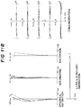
- FIG. 1 is a diagram illustrating a lens configuration of a zoom optical system according to Example 1 of the present embodiment.
- FIGS. 2A, 2B, and 2C are graphs showing various aberrations of the zoom optical system according to Example 1 upon focusing on infinity, respectively in a wide angle end state, an intermediate focal length state, and a telephoto end state.
- FIGS. 3A, 3B, and 3C are graphs showing various aberrations of the zoom optical system according to Example 1 upon focusing on a short distant object, respectively in the wide angle end state, the intermediate focal length state, and the telephoto end state.
- FIG. 4 is a diagram illustrating a lens configuration of a zoom optical system according to Example 2 of the present embodiment.
- FIGS. 5A, 5B, and 5C are graphs showing various aberrations of the zoom optical system according to Example 2 upon focusing on infinity, respectively in the wide angle end state, the intermediate focal length state, and the telephoto end state.
- FIGS. 6A, 6B, and 6C are graphs showing various aberrations of the zoom optical system according to Example 2 upon focusing on a short distant object, respectively in the wide angle end state, the intermediate focal length state, and the telephoto end state.
- FIG. 7 is a diagram illustrating a lens configuration of a zoom optical system according to Example 3 of the present embodiment.
- FIGS. 8A, 8B, and 8C are graphs showing various aberrations of the zoom optical system according to Example 3 upon focusing on infinity, respectively in the wide angle end state, the intermediate focal length state, and the telephoto end state.
- FIGS. 9A, 9B, and 9C are graphs showing various aberrations of the zoom optical system according to Example 3 upon focusing on a short distant object, respectively in the wide angle end state, the intermediate focal length state, and the telephoto end state.
- FIG. 10 is a diagram illustrating a lens configuration of a zoom optical system according to Example 4 of the present embodiment.
- FIGS. 11A, 11B, and 11C are graphs showing various aberrations of the zoom optical system according to Example 4 upon focusing on infinity, respectively in the wide angle end state, the intermediate focal length state, and the telephoto end state.
- FIGS. 12A, 12B, and 12C are graphs showing various aberrations of the zoom optical system according to Example 4 upon focusing on a short distant object, respectively in the wide angle end state, the intermediate focal length state, and the telephoto end state.
- FIG. 13 is a diagram illustrating a configuration of a camera comprising the zoom optical system according to the present embodiment.
- FIG. 14 is a flowchart illustrating a method for manufacturing the zoom optical system according to the present embodiment.
- a zoom optical system ZL( 1 ) as an example of a zoom optical system (zoom lens) ZL according to the present embodiment comprises, in order from an object: a first lens group G 1 having positive refractive power; a second lens group G 2 having negative refractive power; and a subsequent group GR (third lens group G 3 ) including at least one lens group.
- the subsequent group GR comprises a focusing group Gfc having negative refractive power for focusing (moves upon focusing on a short distant object from an infinite distant object).
- the first lens group G 1 comprises a 1-1st lens L 11 that has positive refractive power and is disposed closest to the object.
- the third lens group G 3 has positive refractive power.
- the zoom optical system ZL may also be a zoom optical system ZL( 2 ) illustrated in FIG. 4 , a zoom optical system ZL( 3 ) illustrated in FIG. 7 , or a zoom optical system ZL( 4 ) illustrated in FIG. 10 .
- the zoom optical system ZL( 2 ) comprises the first lens group G 1 , the second lens group G 2 , and the subsequent group GR.
- the subsequent group GR consists of the third lens group G 3 , as in the case of the zoom optical system ZL( 1 ). While in the zoom optical systems ZL( 3 ) and ZL( 4 ), the subsequent group GR consists of the third lens group G 3 , a fourth lens group G 4 , and a fifth lens group G 5 respectively.
- the zoom optical system ZL comprises at least three lens groups, and the distances among the lens groups change upon zooming.
- successful aberration correction can be achieved upon zooming.
- the focusing group Gfc is disposed in the subsequent group GR, and thus can be small and light weight.
- the focusing group Gfc comprises three or less lenses. However, this should not be construed in a limiting sense.
- the 1-1st lens L 11 having positive refractive power and being disposed closest to the object in the first lens group G 1 , a spherical aberration in a telephoto end state can be successfully corrected.
- the 1-1st lens L 11 may be a single lens or may be cemented with another lens to be a part of a cemented lens.
- the subsequent group GR comprises at least one lens group, and preferably has positive refractive power as a whole.
- Examples of the configuration of the lens group forming the subsequent group GR include a configuration consisting of a third lens group having positive refractive power; a configuration consisting of a third lens group having positive refractive power, a fourth lens group having negative refractive power, and a fifth lens group having positive refractive power; and a configuration consisting of a third lens group having negative refractive power, a fourth lens group having positive refractive power, a fifth lens group having negative refractive power, and a sixth lens group having positive refractive power.
- the distance among the lens groups forming the subsequent group GR changes at least upon zooming.
- the subsequent group GR preferably comprises a lens disposed to an object side of the focusing group Gfc and a lens disposed to an image side of the focusing group Gfc.
- the zoom optical system ZL according to the present embodiment having the configuration described above preferably satisfies the following conditional expression. 0.20 ⁇ f 1/ fR ⁇ 0.85 (1)
- f1 denotes a focal length of the first lens group G 1 .
- fR denotes a focal length of a lens component, in the subsequent group GR, closest to an image surface.
- the conditional expression (1) is for setting an appropriate range of a ratio between the focal lengths of the first lens group G 1 and the lens component, in the subsequent group GR, closest to the image surface.
- Various aberrations including the spherical aberration can be successfully corrected when the conditional expression (1) is satisfied.
- a value higher than the upper limit value of the conditional expression (1) leads to large refractive power of the lens component, in the subsequent group GR, closest to the image surface, resulting in extremely large distortion that is difficult to correct.
- the effects of the present embodiment can be more effectively guaranteed with the upper limit value of the conditional expression (1) set to be 0.80.
- the upper limit value of the conditional expression (1) is preferably set to be 0.75.
- a value lower than the lower limit value of the conditional expression (1) leads to large refractive power of the first lens group G 1 , rendering various aberrations including the spherical aberration difficult to correct.
- the effects of the present embodiment can be more effectively guaranteed with the lower limit value of the conditional expression (1) set to be 0.30.
- the lower limit value of the conditional expression (1) is preferably set to be 0.40.
- the zoom optical system according to the present embodiment preferably satisfies the following conditional expression (2). 4.30 ⁇ f 1/( ⁇ f 2) ⁇ 5.00 (2)
- f1 denotes a focal length of the first lens group G 1 .
- f2 denotes a focal length of the second lens group G 2 .
- the conditional expression (2) is for setting an appropriate range of a ratio between the focal lengths of the first lens group G 1 and the second lens group G 2 . Variation of various aberrations including the spherical aberration can be prevented upon zooming when the conditional expression (2) is satisfied.
- a value higher than the upper limit value of the conditional expression (2) leads to large refractive power of the second lens group G 2 , rendering various aberrations including the spherical aberration difficult to correct.
- the effects of the present embodiment can be more effectively guaranteed with the upper limit value of the conditional expression (2) set to be 4.95.
- the upper limit value of the conditional expression (2) is preferably set to be 4.90.
- a value lower than the lower limit value of the conditional expression (2) leads to large refractive power of the first lens group G 1 , rendering various aberrations including the spherical aberration difficult to correct.
- the effects of the present embodiment can be more effectively guaranteed with the lower limit value of the conditional expression (2) set to be 4.35.
- the lower limit value of the conditional expression (2) is preferably set to be 4.40.
- the zoom optical system according to the present embodiment preferably has a configuration in which the first lens group G 1 moves toward the object upon zooming from a wide angle end state to the telephoto end state.
- a short total length of the lenses in the wide angle end state can be achieved, whereby a small size of the zoom optical system can be achieved.
- the zoom optical system according to the present embodiment preferably includes the focusing group Gfc including at least one lens having positive refractive power and at least one lens having negative refractive power.
- the zoom optical system according to the present embodiment preferably satisfies the following conditional expression (3). 1.00 ⁇ nFP/nFN ⁇ 1.20 (3)
- nFP denotes a refractive index of a lens with the largest positive refractive power in the focusing group Gfc
- nFN denotes a refractive index of a lens with the largest negative refractive power in the focusing group Gfc.
- the conditional expression (3) is for defining an appropriate range of a ratio between the refractive indices of the lens with the largest positive refractive power and the lens with the largest negative refractive power in the focusing group Gfc. Variation of various aberrations including the spherical aberration can be prevented upon focusing when the conditional expression (3) is satisfied.
- a value higher than the upper limit value of the conditional expression (3) leads to small refractive index of the lens with the largest negative refractive power, resulting in extremely large various aberrations including the spherical aberration upon focusing that are difficult to correct.
- the effects of the present embodiment can be more effectively guaranteed with the upper limit value of the conditional expression (3) set to be 1.18.
- the upper limit value of the conditional expression (3) is preferably set to be 1.13.
- a value lower than the lower limit value of the conditional expression (3) leads to small refractive index of the lens with the largest positive refractive power, rendering variation of various aberrations including the spherical aberration upon focusing difficult to correct.
- the effects of the present embodiment can be more effectively guaranteed with the lower limit value of the conditional expression (3) set to be 1.01.
- the lower limit value of the conditional expression (3) is preferably set to be 1.02.
- the zoom optical system according to the present embodiment preferably satisfies the following conditional expression (4). 0.52 ⁇ FP/ ⁇ FN ⁇ 0.82 (4)
- vFP denotes an Abbe number of the lens with the largest positive refractive power in the focusing group Gfc
- vFN denotes an Abbe number of the lens with the largest negative refractive power in the focusing group Gfc.
- the conditional expression (4) is for defining an appropriate range of a ratio between the Abbe number of the lens with the largest positive refractive power and the Abbe number of the lens with the largest negative refractive power in the focusing group Gfc. Variation of a chromatic aberration can be prevented upon focusing when the conditional expression (4) is satisfied.
- a value higher than the upper limit value of the conditional expression (4) leads to a small Abbe number of the lens with the largest negative refractive power, resulting in an extremely large chromatic aberration upon focusing that is difficult to correct.
- the effects of the present embodiment can be more effectively guaranteed with the upper limit value of the conditional expression (4) set to be 0.80.
- the upper limit value of the conditional expression (4) is preferably set to be 0.78.
- a value lower than the lower limit value of the conditional expression (4) leads to a small Abbe number of the lens with the largest positive refractive power, rendering variation of the chromatic aberration upon focusing difficult to correct.
- the effects of the present embodiment can be more effectively guaranteed with the lower limit value of the conditional expression (4) set to be 0.54.
- the lower limit value of the conditional expression (4) is preferably set to be 0.56.
- the zoom optical system according to the present embodiment preferably includes the first lens group G 1 including, in order from an object: the 1-1st lens having positive refractive power; a 1-2nd lens having negative refractive power; and a 1-3rd lens having positive refractive power.
- the zoom optical system according to the present embodiment preferably includes the second lens group G 2 including, in order from an object: a 2-1st lens having negative refractive power; a 2-2nd lens having positive refractive power; and a 2-3rd lens having negative refractive power.
- the second lens group G 2 including, in order from an object: a 2-1st lens having negative refractive power; a 2-2nd lens having positive refractive power; and a 2-3rd lens having negative refractive power.
- the optical apparatus includes the zoom optical system with the configuration described above.
- a camera (optical apparatus) including the zoom optical system ZL is described, as a specific example, with reference to FIG. 13 .
- This camera 1 is a digital camera including the zoom optical system according to the present embodiment serving as an imaging lens 2 as illustrated in FIG. 13 .
- the imaging lens 2 collects light from an object (subject) (not illustrated), and then the light reaches an image sensor 3 .
- an image based on the light from the subject is formed with the image sensor 3 to be stored as a subject image in a memory (not illustrated).
- the camera may be a mirrorless camera, or may be a single lens reflex camera having a quick return mirror.
- the camera 1 including the zoom optical system ZL serving as the imaging lens 2 can have a focus lens group that is small and light weight, and thus quick and silent AF can be achieved without using a large barrel. Furthermore, with this configuration, variation of aberrations upon zooming from the wide angle end state to the telephoto end state, as well as variation of aberrations upon focusing on a short distant object from an infinite distant object can be successfully prevented, whereby excellent optical performance can be implemented.
- the first lens group G 1 having positive refractive power, the second lens group G 2 having negative refractive power, and the subsequent group GR including at least one lens group are disposed in a barrel in order from the object (step ST 1 ).
- the lens groups are configured in such a manner that upon zooming, the distances between the first lens group G 1 and the second lens group G 2 and between the second lens group G 2 and the subsequent group GR change (step ST 2 ).
- the focusing group Gfc having negative refractive power for focusing is provided in the subsequent group GR and the 1-1st lens L 11 that has positive refractive power and is disposed closest to the object is provided in the first lens group G 1 (step ST 3 ).
- the lenses are arranged in the lens barrel in such a manner that at least the conditional expression (1) described above is satisfied (step ST 4 ).
- FIG. 1 , FIG. 4 , FIG. 7 , and FIG. 10 are cross-sectional views illustrating configurations and refractive power distributions of the zoom optical systems ZL ⁇ ZL( 1 ) to ZL( 4 ) ⁇ according to Examples 1 to 4.
- the directions in which the lens groups are moved along the optical axis upon zooming from the wide angle end state (W) to the telephoto end state (T) are shown by arrows.
- a direction in which the focusing group Gfc moves upon focusing on a short distant object from infinity is shown by an arrow appended with “focusing”.
- a combination of a sign G and a number represents each lens group
- a combination of a sign L and a number represents each lens.
- lens groups and the like are each denoted with a combination of the reference sign and numeral independently from other Examples to prevent cumbersomeness due to an excessively wide variety or a large number of signs and numerals.
- components in different Examples denoted with the same combination of reference sign and numeral does not necessarily have the same configuration.
- Table 1 to Table 20 include Table 1 to Table 5 that are specification tables of Example 1, Table 6 to Table 10 that are specification tables of Example 2, Table 11 to Table 15 that are specification tables of Example 3, and Table 16 to Table 20 that are specification tables of Example 4.
- d-line (wavelength 587.562 nm) and g-line (wavelength 435.835 nm) are selected as calculation targets of the aberration characteristics.
- a surface number represents an order of an optical surface from the object side in a traveling direction of a light beam
- R represents a radius of curvature of each optical surface (with a surface having the center of curvature position on the image side provided with a positive value)
- D represents a distance between each optical surface and the next optical surface (or the image surface) on the optical axis
- nd represents a refractive index of a material of an optical member with respect to the d-line
- vd represents an Abbe number of the material of the optical member based on the d-line.
- object surface represents an object surface
- ⁇ of the radius of curvature
- (stop S) represents the aperture stop S
- image surface represents an image surface I.
- the refractive index nd 1.00000 of air is omitted.
- f represents a focal length of the whole zoom lens
- FNo represents F number
- 2 ⁇ represents an angle of view ( ⁇ represents a half angle of view (unit: °))
- Ymax represents the maximum image height.
- Back focus (BF) represents a distance between a lens last surface and the image surface I on the optical axis upon focusing on infinity
- TL represents a distance obtained by adding BF to a distance between a lens forefront surface and a lens last surface on the optical axis upon focusing on infinity.
- Table [Variable distance data] includes surface distances d 5 , d 10 , d 21 , and d 24 corresponding to surfaces corresponding to surface numbers 5 , 10 , 21 , and 24 appended with “variable” in Table [Lens specifications] and the next surface.
- the surface distances d 5 , d 10 , d 21 , and d 24 are provided for each of the zooming states including the wide angle end state (W), the intermediate focal length state (M), and the telephoto end state (T) upon focusing on infinity and upon focusing on a short distant object.
- Table [Lens group data] includes the group starting surface (surface closest to the object) and the focal length of each of the first to the third lens groups.
- Table [Conditional expression corresponding value] includes values corresponding to the conditional expressions (1) to (4).
- the focal length f, the radius of curvature R, the surface distance D and the other units of length described below as all the specification values, which are generally described with “mm” unless otherwise noted should not be construed in a limiting sense because the optical system proportionally expanded or reduced can have a similar or the same optical performance.
- FIG. 1 is a diagram illustrating a lens configuration of a zoom optical system according to Example 1 of the present embodiment.
- the zoom optical system ZL( 1 ) according to Example 1 consists of, in order from an object: a first lens group G 1 having positive refractive power; a second lens group G 2 having negative refractive power; and a third lens group G 3 having positive refractive power.
- the third lens group G 3 forms the subsequent group GR.
- a sign (+) or ( ⁇ ) provided to a sign of each lens group represents refractive power of the lens group.
- the aperture stop S is provided in the third lens group G 3 , and the image surface I is disposed to the image side of the third lens group G 3 .
- the first lens group G 1 consists of, in order from the object, a positive lens L 11 having a biconvex shape and a cemented positive lens consisting of a negative meniscus lens L 12 having a convex surface facing the object and a positive meniscus lens L 13 having a convex surface facing the object.
- the second lens group G 2 consists of, in order from the object, a cemented negative lens consisting of a negative lens L 21 having a biconcave shape and a positive meniscus lens L 22 having a convex surface facing the object and a negative lens L 23 having a biconcave shape.
- the third lens group G 3 consists of, in order from the object, a positive lens L 31 having a biconvex shape, the aperture stop S, a cemented positive lens consisting of a positive lens L 32 having a biconvex shape and a negative lens L 33 having a biconcave shape, a cemented positive lens consisting of a negative meniscus lens L 34 having a convex surface facing the object and a positive lens L 35 having a biconvex shape, a positive meniscus lens L 36 having a convex surface facing the object, a cemented negative lens consisting of a positive meniscus lens L 37 having a concave surface facing the object and a negative lens L 38 having a biconcave shape, and a positive lens L 39 having a biconvex shape.
- the cemented negative lens consisting of the positive meniscus lens L 37 and the negative lens L 38 in the third lens group G 3 moves toward the image surface upon focusing from a long distant object to a short distant object.
- the second lens group G 2 preferably serves as a vibration-proof lens group, with a displacement component in a direction orthogonal to the optical axis, to be in charge of image blur correction on the image surface I (image stabilization, camera shake correction).
- Table 1 to Table 5 below list specification values of the optical system according to Example 1.
- Conditional expression (1)f1/fR 0.722
- Conditional expression (2)f1/( ⁇ f2) 4.626
- Conditional expression (3)nFP/nFN 1.031
- Conditional expression (4) ⁇ FP/ ⁇ FN 0.635
- FIGS. 2A, 2B, and 2C are graphs showing various aberrations of the zoom optical system according to Example 1 upon focusing on infinity, respectively in the wide angle end state, the intermediate focal length state, and the telephoto end state.
- FIGS. 3A, 3B, and 3C are graphs showing various aberrations of the zoom optical system according to Example 1 upon focusing on a short distant object, respectively in the wide angle end state, the intermediate focal length state, and the telephoto end state.
- FNO denotes an F number
- NA denotes the number of apertures
- Y denotes an image height
- the spherical aberration graphs illustrate an F number or the number of apertures corresponding to the maximum aperture
- astigmatism aberration graphs and distortion aberration graphs illustrate the maximum image height
- coma aberration graphs illustrate values of image heights.
- the zoom optical system according to this Example can achieve excellent imaging performance with various aberrations successfully corrected from the wide angle end state to the telephoto end state, and can achieve excellent imaging performance upon focusing on a short distant object.
- FIG. 4 is a diagram illustrating a lens configuration of a zoom optical system according to Example 2 of the present embodiment.
- the zoom optical system ZL( 2 ) according to Example 2 consists of, in order from an object: a first lens group G 1 having positive refractive power; a second lens group G 2 having negative refractive power; and a third lens group G 3 having positive refractive power.
- the third lens group G 3 forms the subsequent group GR.
- the aperture stop S is provided in the third lens group G 3 , and the image surface I is disposed to the image side of the third lens group G 3 .
- the first lens group G 1 consists of, in order from the object, a positive lens L 11 having a biconvex shape and a cemented positive lens consisting of a negative meniscus lens L 12 having a convex surface facing the object and a positive meniscus lens L 13 having a convex surface facing the object.
- the second lens group G 2 consists of, in order from the object, a cemented negative lens consisting of a negative lens L 21 having a biconcave shape and a positive meniscus lens L 22 having a convex surface facing the object and a negative meniscus lens L 23 having a concave surface facing the object.
- the third lens group G 3 consists of, in order from the object, a positive lens L 31 having a biconvex shape, a cemented positive lens consisting of a positive lens L 32 having a biconvex shape and a negative lens L 33 having a biconcave shape, the aperture stop S, a cemented positive lens consisting of a negative meniscus lens L 34 having a convex surface facing the object and a positive lens L 35 having a biconvex shape, a positive meniscus lens L 36 having a convex surface facing the object, a cemented negative lens consisting of a positive meniscus lens L 37 having a concave surface facing the object and a negative lens L 38 having a biconcave shape, and a positive meniscus lens L 39 having a convex surface facing the object.
- the cemented negative lens consisting of the positive meniscus lens L 37 and the negative lens L 38 in the third lens group G 3 moves toward the image surface upon focusing from a long distant object to a short distant object.
- the second lens group G 2 preferably serves as a vibration-proof lens group, with a displacement component in a direction orthogonal to the optical axis, to be in charge of image blur correction on the image surface I (image stabilization, camera shake correction).
- Table 6 to Table 10 below list specification values of the optical system according to Example 2.
- Conditional expression (1)f1/fR 0.680
- Conditional expression (2)f1/( ⁇ f2) 4.855
- Conditional expression (3)nFP/nFN 1.033
- Conditional expression (4) ⁇ FP/ ⁇ FN 0.650
- FIGS. 5A, 5B, and 5C are graphs showing various aberrations of the zoom optical system according to Example 2 upon focusing on infinity, respectively in the wide angle end state, the intermediate focal length state, and the telephoto end state.
- FIGS. 6A, 6B, and 6C are graphs showing various aberrations of the zoom optical system according to Example 2 upon focusing on a short distant object, respectively in the wide angle end state, the intermediate focal length state, and the telephoto end state. It can be seen in these aberration graphs that the zoom optical system according to this Example can achieve excellent imaging performance with various aberrations successfully corrected from the wide angle end state to the telephoto end state, and can achieve excellent imaging performance upon focusing on a short distant object.
- FIG. 7 is a diagram illustrating a lens configuration of a zoom optical system according to Example 3 of the present embodiment.
- the zoom optical system ZL( 3 ) according to Example 3 consists of, in order from the object: a first lens group G 1 having positive refractive power; a second lens group G 2 having negative refractive power; a third lens group G 3 having positive refractive power; a fourth lens group G 4 having negative refractive power; and a fifth lens group G 5 having positive refractive power.
- the third to the fifth lens groups G 3 to G 5 form the subsequent group GR having positive refractive power as a whole.
- the first lens group G 1 consists of, in order from the object, a positive lens L 11 having a biconvex shape and a cemented positive lens consisting of a negative meniscus lens L 12 having a convex surface facing the object and a positive meniscus lens L 13 having a convex surface facing the object.
- the second lens group G 2 consists of, in order from the object, a cemented negative lens consisting of a negative lens L 21 having a biconcave shape and a positive meniscus lens L 22 having a convex surface facing the object and a negative lens L 23 having a biconcave shape.
- the third lens group G 3 consists of, in order from the object, a positive lens L 31 having a biconvex shape, a cemented positive lens consisting of a positive lens L 32 having a biconvex shape and a negative lens L 33 having a biconcave shape, the aperture stop S, a cemented positive lens consisting of a negative meniscus lens L 34 having a convex surface facing the object and a positive lens L 35 having a biconvex shape, and a positive meniscus lens L 36 having a convex surface facing the object.
- the fourth lens group G 4 consists of a cemented negative lens consisting of a positive meniscus lens L 41 having a concave surface facing the object and a negative lens L 42 having a biconcave shape.
- the fifth lens group G 5 consists of a positive meniscus lens L 51 having a convex surface facing the object.
- the fourth lens group G 4 moves toward the image surface upon focusing from a long distant object to a short distant object.
- the second lens group G 2 preferably serves as a vibration-proof lens group, with a displacement component in a direction orthogonal to the optical axis, to be in charge of image blur correction on the image surface I (image stabilization, camera shake correction).
- Table 11 to Table 15 below list specification values of the optical system according to Example 3.
- Conditional expression (1)f1/fR 0.440
- Conditional expression (2)f1/( ⁇ f2) 4.585
- Conditional expression (3)nFP/nFN 1.050
- Conditional expression (4) ⁇ FP/ ⁇ FN 0.602
- FIGS. 8A, 8B, and 8C are graphs showing various aberrations of the zoom optical system according to Example 3 upon focusing on infinity, respectively in the wide angle end state, the intermediate focal length state, and the telephoto end state.
- FIGS. 9A, 9B, and 9C are graphs showing various aberrations of the zoom optical system according to Example 3 upon focusing on a short distant object, respectively in the wide angle end state, the intermediate focal length state, and the telephoto end state. It can be seen in these aberration graphs that the zoom optical system according to this Example can achieve excellent imaging performance with various aberrations successfully corrected from the wide angle end state to the telephoto end state, and can achieve excellent imaging performance upon focusing on a short distant object.
- FIG. 10 is a diagram illustrating a lens configuration of a zoom optical system according to Example 4 of the present embodiment.
- the zoom optical system ZL( 4 ) according to Example 4 consists of, in order from the object: a first lens group G 1 having positive refractive power; a second lens group G 2 having negative refractive power; a third lens group G 3 having positive refractive power; a fourth lens group G 4 having negative refractive power; and a fifth lens group G 5 having positive refractive power.
- the third to the fifth lens groups G 3 to G 5 form the subsequent group GR having positive refractive power as a whole.
- the first lens group G 1 consists of, in order from the object, a positive lens L 11 having a biconvex shape and a cemented positive lens consisting of a negative meniscus lens L 12 having a convex surface facing the object and a positive meniscus lens L 13 having a convex surface facing the object.
- the second lens group G 2 consists of, in order from the object, a cemented negative lens consisting of a negative lens L 21 having a biconcave shape and a positive meniscus lens L 22 having a convex surface facing the object and a negative lens L 23 having a biconcave shape.
- the third lens group G 3 consists of, in order from the object, a positive lens L 31 having a biconvex shape, a cemented positive lens consisting of a positive lens L 32 having a biconvex shape and a negative lens L 33 having a biconcave shape, the aperture stop S, a cemented positive lens consisting of a negative meniscus lens L 34 having a convex surface facing the object and a positive lens L 35 having a biconvex shape, and a positive meniscus lens L 36 having a convex surface facing the object.
- the fourth lens group G 4 consists of a cemented negative lens consisting of a positive meniscus lens L 41 having a concave surface facing the object and a negative lens L 42 having a biconcave shape and a negative meniscus lens L 43 having a convex surface facing the object.
- the fifth lens group G 5 consists of a positive meniscus lens L 51 having a convex surface facing the object.
- the fourth lens group G 4 moves toward the image surface upon focusing from a long distant object to a short distant object.
- the second lens group G 2 preferably serves as a vibration-proof lens group, with a displacement component in a direction orthogonal to the optical axis, to be in charge of image blur correction on the image surface I (image stabilization, camera shake correction).
- Conditional expression (1)f1/fR 0.747
- Conditional expression (2)f1/( ⁇ f2) 4.544
- Conditional expression (3)nFP/nFN 1.050
- Conditional expression (4) ⁇ FP/ ⁇ FN 0.602
- FIGS. 11A, 11B, and 11C are graphs showing various aberrations of the zoom optical system according to Example 4 upon focusing on infinity, respectively in the wide angle end state, the intermediate focal length state, and the telephoto end state.
- FIGS. 12A, 12B, and 12C are graphs showing various aberrations of the zoom optical system according to Example 4 upon focusing on a short distant object, respectively in the wide angle end state, the intermediate focal length state, and the telephoto end state. It can be seen in these aberration graphs that the zoom optical system according to this Example can achieve excellent imaging performance with various aberrations successfully corrected from the wide angle end state to the telephoto end state, and can achieve excellent imaging performance upon focusing on a short distant object.
- the focus lens group is small and light weight so that quick and quiet AF can be implemented without using a large barrel. Furthermore, a zoom optical system successfully preventing variation of aberrations upon zooming from the wide angle end state to the telephoto end state, as well as variation of aberrations upon focusing on a short distant object from an infinite distant object can be implemented.
- the zoom optical system according the present embodiment having three or five lens groups are described above. However, this should not be construed in a limiting sense, and a zoom optical system with other lens group configurations (for example, a configuration with four or six lens groups or the like) may be employed. More specifically, the zoom optical system according to the present embodiment may be further provided with a lens or a lens group closest to an object or further provided with a lens or a lens group closest to the image surface.
- the lens group is a portion including at least one lens separated from another lens with a distance varying upon zooming.
- the focusing group is a portion including at least one lens separated from another lens with a distance varying upon focusing.
- the focusing group may be provided for focusing from an infinite distant object to a short distant object, with a single or a plurality of lens groups or a partial lens group moved in the optical axis direction.
- the focusing group can be applied to auto focus, and is suitable for motor driving for auto focus (using supersonic wave motors, etc.).
- the lens surface may be formed to have a spherical surface or a planer surface, or may be formed to have an aspherical shape.
- the lens surface having a spherical surface or a planer surface features easy lens processing and assembly adjustment, which leads to the processing and assembly adjustment less likely to involve an error compromising the optical performance, and thus is preferable. Furthermore, there is an advantage that a rendering performance is not largely compromised even when the image surface is displaced.
- the lens surface having an aspherical shape may be achieved with any one of an aspherical shape formed by grinding, a glass-molded aspherical shape obtained by molding a glass piece into an aspherical shape, and a composite type aspherical surface obtained by providing an aspherical shape resin piece on a glass surface.
- a lens surface may be a diffractive surface.
- the lens may be a gradient index lens (GRIN lens) or a plastic lens.
- the aperture stop is preferably disposed in the neighborhood of or within the third lens group.
- a lens frame may serve as the aperture stop so that the member serving as the aperture stop needs not to be provided.
- the lens surfaces may be provided with an antireflection film featuring high transmittance over a wide range of wavelengths to achieve an excellent optical performance with reduced flare and ghosting and increased contrast.
- an excellent optical performance with reduced flare and ghosting and increased contrast can be achieved.
Landscapes
- Physics & Mathematics (AREA)
- General Physics & Mathematics (AREA)
- Optics & Photonics (AREA)
- Nonlinear Science (AREA)
- Lenses (AREA)
Applications Claiming Priority (3)
| Application Number | Priority Date | Filing Date | Title |
|---|---|---|---|
| JP2015234010 | 2015-11-30 | ||
| JP2015-234010 | 2015-11-30 | ||
| PCT/JP2016/085190 WO2017094660A1 (ja) | 2015-11-30 | 2016-11-28 | 変倍光学系、光学機器および変倍光学系の製造方法 |
Related Parent Applications (1)
| Application Number | Title | Priority Date | Filing Date |
|---|---|---|---|
| PCT/JP2016/085190 A-371-Of-International WO2017094660A1 (ja) | 2015-11-30 | 2016-11-28 | 変倍光学系、光学機器および変倍光学系の製造方法 |
Related Child Applications (1)
| Application Number | Title | Priority Date | Filing Date |
|---|---|---|---|
| US17/099,980 Division US12007623B2 (en) | 2015-11-30 | 2020-11-17 | Zoom optical system, optical apparatus and method for manufacturing the zoom optical system |
Publications (2)
| Publication Number | Publication Date |
|---|---|
| US20180348476A1 US20180348476A1 (en) | 2018-12-06 |
| US10877240B2 true US10877240B2 (en) | 2020-12-29 |
Family
ID=58796717
Family Applications (1)
| Application Number | Title | Priority Date | Filing Date |
|---|---|---|---|
| US15/777,910 Active 2037-06-07 US10877240B2 (en) | 2015-11-30 | 2016-11-28 | Zoom optical system, optical apparatus and method for manufacturing the zoom optical system |
Country Status (4)
| Country | Link |
|---|---|
| US (1) | US10877240B2 (zh) |
| JP (1) | JP6583429B2 (zh) |
| CN (1) | CN108292031A (zh) |
| WO (1) | WO2017094660A1 (zh) |
Cited By (2)
| Publication number | Priority date | Publication date | Assignee | Title |
|---|---|---|---|---|
| US20210072497A1 (en) * | 2015-11-30 | 2021-03-11 | Nikon Corporation | Zoom optical system, optical apparatus and method for manufacturing the zoom optical system |
| US12007623B2 (en) * | 2015-11-30 | 2024-06-11 | Nikon Corporation | Zoom optical system, optical apparatus and method for manufacturing the zoom optical system |
Families Citing this family (5)
| Publication number | Priority date | Publication date | Assignee | Title |
|---|---|---|---|---|
| JP7115963B2 (ja) * | 2018-11-27 | 2022-08-09 | 富士フイルム株式会社 | ズームレンズ及び撮像装置 |
| JP7218762B2 (ja) * | 2018-12-26 | 2023-02-07 | 株式会社ニコン | 変倍光学系および光学機器 |
| JP7243841B2 (ja) * | 2019-08-29 | 2023-03-22 | 株式会社ニコン | 変倍光学系および光学機器 |
| CN111221114B (zh) * | 2020-01-18 | 2021-12-10 | 东莞锐星视觉技术有限公司 | 一种高倍率高分辨率的变倍镜头 |
| CN115220205B (zh) * | 2022-09-01 | 2024-01-30 | 舜宇光学(中山)有限公司 | 变焦镜头 |
Citations (10)
| Publication number | Priority date | Publication date | Assignee | Title |
|---|---|---|---|---|
| JPH04293007A (ja) | 1991-03-20 | 1992-10-16 | Canon Inc | ズームレンズ |
| US20050219708A1 (en) | 2004-03-30 | 2005-10-06 | Nikon Corporation | Zoom lens system |
| JP2011209347A (ja) | 2010-03-29 | 2011-10-20 | Sony Corp | ズームレンズ及び撮像装置 |
| JP2013195627A (ja) | 2012-03-19 | 2013-09-30 | Casio Comput Co Ltd | ズームレンズ及び投射型表示装置 |
| US20140009652A1 (en) * | 2012-07-09 | 2014-01-09 | Canon Kabushiki Kaisha | Zoom lens and image pickup apparatus having the same |
| US20140146216A1 (en) | 2012-11-28 | 2014-05-29 | Canon Kabushiki Kaisha | Zoom lens and image pickup apparatus |
| US20140211029A1 (en) | 2013-01-30 | 2014-07-31 | Canon Kabushiki Kaisha | Zoom lens and image pickup apparatus including the same |
| US20140347546A1 (en) * | 2013-05-24 | 2014-11-27 | Tamron Co., Ltd. | Zoom Lens and Imaging Apparatus |
| JP2015138178A (ja) | 2014-01-23 | 2015-07-30 | キヤノン株式会社 | ズームレンズおよびそれを有する撮像装置 |
| US20150309291A1 (en) * | 2014-04-25 | 2015-10-29 | Fujifilm Corporation | Zoom lens and imaging apparatus |
-
2016
- 2016-11-28 JP JP2017553837A patent/JP6583429B2/ja active Active
- 2016-11-28 WO PCT/JP2016/085190 patent/WO2017094660A1/ja active Application Filing
- 2016-11-28 CN CN201680069806.3A patent/CN108292031A/zh active Pending
- 2016-11-28 US US15/777,910 patent/US10877240B2/en active Active
Patent Citations (12)
| Publication number | Priority date | Publication date | Assignee | Title |
|---|---|---|---|---|
| JPH04293007A (ja) | 1991-03-20 | 1992-10-16 | Canon Inc | ズームレンズ |
| US20050219708A1 (en) | 2004-03-30 | 2005-10-06 | Nikon Corporation | Zoom lens system |
| CN101866045A (zh) | 2004-03-30 | 2010-10-20 | 株式会社尼康 | 具有减振机构的变焦透镜系统 |
| JP2011209347A (ja) | 2010-03-29 | 2011-10-20 | Sony Corp | ズームレンズ及び撮像装置 |
| JP2013195627A (ja) | 2012-03-19 | 2013-09-30 | Casio Comput Co Ltd | ズームレンズ及び投射型表示装置 |
| US20140009652A1 (en) * | 2012-07-09 | 2014-01-09 | Canon Kabushiki Kaisha | Zoom lens and image pickup apparatus having the same |
| US20140146216A1 (en) | 2012-11-28 | 2014-05-29 | Canon Kabushiki Kaisha | Zoom lens and image pickup apparatus |
| US20140211029A1 (en) | 2013-01-30 | 2014-07-31 | Canon Kabushiki Kaisha | Zoom lens and image pickup apparatus including the same |
| CN103969812A (zh) | 2013-01-30 | 2014-08-06 | 佳能株式会社 | 变焦透镜和包括所述变焦透镜的图像拾取装置 |
| US20140347546A1 (en) * | 2013-05-24 | 2014-11-27 | Tamron Co., Ltd. | Zoom Lens and Imaging Apparatus |
| JP2015138178A (ja) | 2014-01-23 | 2015-07-30 | キヤノン株式会社 | ズームレンズおよびそれを有する撮像装置 |
| US20150309291A1 (en) * | 2014-04-25 | 2015-10-29 | Fujifilm Corporation | Zoom lens and imaging apparatus |
Non-Patent Citations (5)
| Title |
|---|
| English translation of International Preliminary Report on Patentability from International Patent Application No. PCT/JP2016/085190, dated Jun. 14, 2018. |
| International Search Report from International Patent Application No. PCT/JP2016/085190, dated Feb. 21, 2017. |
| Office Action dated Jan. 19, 2020, in Chinese Patent Application No. 201680069806.3. |
| Office Action dated Jun. 8, 2020, in Chinese Patent Application No. 201680069806.3. |
| Office Action dated May 14, 2019, in Japanese Patent Application No. 2017-553837. |
Cited By (2)
| Publication number | Priority date | Publication date | Assignee | Title |
|---|---|---|---|---|
| US20210072497A1 (en) * | 2015-11-30 | 2021-03-11 | Nikon Corporation | Zoom optical system, optical apparatus and method for manufacturing the zoom optical system |
| US12007623B2 (en) * | 2015-11-30 | 2024-06-11 | Nikon Corporation | Zoom optical system, optical apparatus and method for manufacturing the zoom optical system |
Also Published As
| Publication number | Publication date |
|---|---|
| JP6583429B2 (ja) | 2019-10-02 |
| WO2017094660A1 (ja) | 2017-06-08 |
| US20180348476A1 (en) | 2018-12-06 |
| CN108292031A (zh) | 2018-07-17 |
| JPWO2017094660A1 (ja) | 2018-09-06 |
| US20210072497A1 (en) | 2021-03-11 |
Similar Documents
| Publication | Publication Date | Title |
|---|---|---|
| US11520127B2 (en) | Variable magnification optical system, optical apparatus, and method for manufacturing variable magnification optical system | |
| US7924511B2 (en) | Optical system, method for focusing, and imaging apparatus equipped therewith | |
| US10761306B2 (en) | Zoom optical system, optical apparatus and method for manufacturing the zoom optical system | |
| US10877240B2 (en) | Zoom optical system, optical apparatus and method for manufacturing the zoom optical system | |
| US11415786B2 (en) | Variable magnification optical system, optical apparatus, and variable magnification optical system manufacturing method | |
| US11668899B2 (en) | Zoom lens, optical apparatus, and method for manufacturing zoom lens | |
| US11592651B2 (en) | Zoom optical system, optical apparatus and method for manufacturing the zoom optical system | |
| US11994746B2 (en) | Zoom lens, optical apparatus and method for manufacturing the zoom lens | |
| US11175484B2 (en) | Variable magnification optical system comprising four lens groups of +−+− or five lens groups of +−+−+ refractive powers, optical equipment, imaging equipment and method for manufacturing variable magnification optical system | |
| US11789246B2 (en) | Zoom lens, optical apparatus and method for manufacturing the zoom lens | |
| US10831004B2 (en) | Zoom optical system, optical apparatus and method for manufacturing the zoom optical system | |
| CN109952524B (zh) | 变倍光学系统以及使用了该变倍光学系统的光学设备和摄像设备 | |
| CN109983385B (zh) | 变倍光学系统以及使用了该变倍光学系统的光学设备和摄像设备 | |
| CN109964161B (zh) | 变倍光学系统、光学设备以及摄像设备 | |
| US10527829B2 (en) | Variable magnification optical system, optical apparatus, and method for manufacturing variable magnification optical system | |
| US10761304B2 (en) | Zoom optical system, optical apparatus and method for manufacturing the zoom optical system | |
| US10831006B2 (en) | Zoom optical system, optical apparatus and method for manufacturing the zoom optical system | |
| US12007623B2 (en) | Zoom optical system, optical apparatus and method for manufacturing the zoom optical system | |
| CN109952523B (zh) | 变倍光学系统以及使用了该变倍光学系统的光学设备和摄像设备 | |
| US10678030B2 (en) | Zoom optical system, optical apparatus and method for manufacturing the zoom optical system | |
| US11086110B2 (en) | Variable magnification optical system, optical apparatus, imaging apparatus and method for manufacturing variable magnification optical system | |
| US20180259753A1 (en) | Variable magnification optical system, optical apparatus, imaging apparatus and method for manufacturing variable magnification optical system |
Legal Events
| Date | Code | Title | Description |
|---|---|---|---|
| FEPP | Fee payment procedure |
Free format text: ENTITY STATUS SET TO UNDISCOUNTED (ORIGINAL EVENT CODE: BIG.); ENTITY STATUS OF PATENT OWNER: LARGE ENTITY |
|
| AS | Assignment |
Owner name: NIKON CORPORATION, JAPAN Free format text: ASSIGNMENT OF ASSIGNORS INTEREST;ASSIGNOR:MACHIDA, KOSUKE;REEL/FRAME:046517/0790 Effective date: 20180711 |
|
| STPP | Information on status: patent application and granting procedure in general |
Free format text: APPLICATION DISPATCHED FROM PREEXAM, NOT YET DOCKETED |
|
| STPP | Information on status: patent application and granting procedure in general |
Free format text: DOCKETED NEW CASE - READY FOR EXAMINATION |
|
| STPP | Information on status: patent application and granting procedure in general |
Free format text: NON FINAL ACTION MAILED |
|
| STPP | Information on status: patent application and granting procedure in general |
Free format text: FINAL REJECTION MAILED |
|
| STPP | Information on status: patent application and granting procedure in general |
Free format text: RESPONSE AFTER FINAL ACTION FORWARDED TO EXAMINER |
|
| STPP | Information on status: patent application and granting procedure in general |
Free format text: RESPONSE TO NON-FINAL OFFICE ACTION ENTERED AND FORWARDED TO EXAMINER |
|
| STPP | Information on status: patent application and granting procedure in general |
Free format text: NOTICE OF ALLOWANCE MAILED -- APPLICATION RECEIVED IN OFFICE OF PUBLICATIONS |
|
| STCF | Information on status: patent grant |
Free format text: PATENTED CASE |