US10876910B2 - Force sensitive resistor - Google Patents
Force sensitive resistor Download PDFInfo
- Publication number
- US10876910B2 US10876910B2 US16/021,933 US201816021933A US10876910B2 US 10876910 B2 US10876910 B2 US 10876910B2 US 201816021933 A US201816021933 A US 201816021933A US 10876910 B2 US10876910 B2 US 10876910B2
- Authority
- US
- United States
- Prior art keywords
- sealed
- force
- force sensitive
- sensitive resistor
- layer
- Prior art date
- Legal status (The legal status is an assumption and is not a legal conclusion. Google has not performed a legal analysis and makes no representation as to the accuracy of the status listed.)
- Active, expires
Links
- 239000000463 material Substances 0.000 claims abstract description 63
- 125000006850 spacer group Chemical group 0.000 claims abstract description 40
- 239000011162 core material Substances 0.000 claims description 3
- 210000003371 toe Anatomy 0.000 description 14
- 210000004744 fore-foot Anatomy 0.000 description 10
- 230000037361 pathway Effects 0.000 description 9
- 210000000452 mid-foot Anatomy 0.000 description 8
- 210000002683 foot Anatomy 0.000 description 5
- 239000000976 ink Substances 0.000 description 5
- 239000000758 substrate Substances 0.000 description 4
- XLYOFNOQVPJJNP-UHFFFAOYSA-N water Substances O XLYOFNOQVPJJNP-UHFFFAOYSA-N 0.000 description 4
- 230000008018 melting Effects 0.000 description 2
- 238000002844 melting Methods 0.000 description 2
- 230000032798 delamination Effects 0.000 description 1
- 239000004744 fabric Substances 0.000 description 1
- 239000006260 foam Substances 0.000 description 1
- 239000006261 foam material Substances 0.000 description 1
- 230000005021 gait Effects 0.000 description 1
- 238000007789 sealing Methods 0.000 description 1
- 210000004243 sweat Anatomy 0.000 description 1
- 238000003466 welding Methods 0.000 description 1
Images


Classifications
-
- G—PHYSICS
- G01—MEASURING; TESTING
- G01L—MEASURING FORCE, STRESS, TORQUE, WORK, MECHANICAL POWER, MECHANICAL EFFICIENCY, OR FLUID PRESSURE
- G01L1/00—Measuring force or stress, in general
- G01L1/20—Measuring force or stress, in general by measuring variations in ohmic resistance of solid materials or of electrically-conductive fluids; by making use of electrokinetic cells, i.e. liquid-containing cells wherein an electrical potential is produced or varied upon the application of stress
-
- G—PHYSICS
- G01—MEASURING; TESTING
- G01L—MEASURING FORCE, STRESS, TORQUE, WORK, MECHANICAL POWER, MECHANICAL EFFICIENCY, OR FLUID PRESSURE
- G01L1/00—Measuring force or stress, in general
- G01L1/18—Measuring force or stress, in general using properties of piezo-resistive materials, i.e. materials of which the ohmic resistance varies according to changes in magnitude or direction of force applied to the material
-
- G—PHYSICS
- G01—MEASURING; TESTING
- G01L—MEASURING FORCE, STRESS, TORQUE, WORK, MECHANICAL POWER, MECHANICAL EFFICIENCY, OR FLUID PRESSURE
- G01L1/00—Measuring force or stress, in general
- G01L1/20—Measuring force or stress, in general by measuring variations in ohmic resistance of solid materials or of electrically-conductive fluids; by making use of electrokinetic cells, i.e. liquid-containing cells wherein an electrical potential is produced or varied upon the application of stress
- G01L1/205—Measuring force or stress, in general by measuring variations in ohmic resistance of solid materials or of electrically-conductive fluids; by making use of electrokinetic cells, i.e. liquid-containing cells wherein an electrical potential is produced or varied upon the application of stress using distributed sensing elements
-
- A—HUMAN NECESSITIES
- A61—MEDICAL OR VETERINARY SCIENCE; HYGIENE
- A61B—DIAGNOSIS; SURGERY; IDENTIFICATION
- A61B5/00—Measuring for diagnostic purposes; Identification of persons
- A61B5/68—Arrangements of detecting, measuring or recording means, e.g. sensors, in relation to patient
- A61B5/6801—Arrangements of detecting, measuring or recording means, e.g. sensors, in relation to patient specially adapted to be attached to or worn on the body surface
- A61B5/6802—Sensor mounted on worn items
- A61B5/6804—Garments; Clothes
- A61B5/6807—Footwear
-
- A43B3/0005—
-
- A—HUMAN NECESSITIES
- A43—FOOTWEAR
- A43B—CHARACTERISTIC FEATURES OF FOOTWEAR; PARTS OF FOOTWEAR
- A43B3/00—Footwear characterised by the shape or the use
- A43B3/34—Footwear characterised by the shape or the use with electrical or electronic arrangements
-
- A—HUMAN NECESSITIES
- A61—MEDICAL OR VETERINARY SCIENCE; HYGIENE
- A61B—DIAGNOSIS; SURGERY; IDENTIFICATION
- A61B5/00—Measuring for diagnostic purposes; Identification of persons
- A61B5/103—Detecting, measuring or recording devices for testing the shape, pattern, colour, size or movement of the body or parts thereof, for diagnostic purposes
- A61B5/1036—Measuring load distribution, e.g. podologic studies
- A61B5/1038—Measuring plantar pressure during gait
-
- G—PHYSICS
- G01—MEASURING; TESTING
- G01L—MEASURING FORCE, STRESS, TORQUE, WORK, MECHANICAL POWER, MECHANICAL EFFICIENCY, OR FLUID PRESSURE
- G01L1/00—Measuring force or stress, in general
- G01L1/14—Measuring force or stress, in general by measuring variations in capacitance or inductance of electrical elements, e.g. by measuring variations of frequency of electrical oscillators
- G01L1/142—Measuring force or stress, in general by measuring variations in capacitance or inductance of electrical elements, e.g. by measuring variations of frequency of electrical oscillators using capacitors
-
- H—ELECTRICITY
- H01—ELECTRIC ELEMENTS
- H01C—RESISTORS
- H01C1/00—Details
- H01C1/02—Housing; Enclosing; Embedding; Filling the housing or enclosure
- H01C1/024—Housing; Enclosing; Embedding; Filling the housing or enclosure the housing or enclosure being hermetically sealed
- H01C1/026—Housing; Enclosing; Embedding; Filling the housing or enclosure the housing or enclosure being hermetically sealed with gaseous or vacuum spacing between the resistive element and the housing or casing
-
- A—HUMAN NECESSITIES
- A61—MEDICAL OR VETERINARY SCIENCE; HYGIENE
- A61B—DIAGNOSIS; SURGERY; IDENTIFICATION
- A61B2562/00—Details of sensors; Constructional details of sensor housings or probes; Accessories for sensors
- A61B2562/02—Details of sensors specially adapted for in-vivo measurements
- A61B2562/0247—Pressure sensors
-
- A—HUMAN NECESSITIES
- A61—MEDICAL OR VETERINARY SCIENCE; HYGIENE
- A61B—DIAGNOSIS; SURGERY; IDENTIFICATION
- A61B2562/00—Details of sensors; Constructional details of sensor housings or probes; Accessories for sensors
- A61B2562/16—Details of sensor housings or probes; Details of structural supports for sensors
- A61B2562/166—Details of sensor housings or probes; Details of structural supports for sensors the sensor is mounted on a specially adapted printed circuit board
Definitions
- the present invention relates to a sealed force-sensitive resistor for use with stretchable materials.
- force sensitive resistors are provided with a lower conductive member formed on a first substrate, and an upper conductive member formed on a second substrate.
- a spacer element is mounted between the first and second substrates. As the conductive members are moved toward and away from each other the resistance of the force sensitive resistor is altered. In this manner the force applied to the resistor can be determined by the change in the resistance.
- the substrates are required to be relatively stiff and resist stretching as otherwise the data from the force sensitive resistor will be corrupted.
- force sensitive resistors are often used in environments which receive significant forces and deformations.
- force sensitive resistors are being used in so-called “smart” clothing.
- the sealed force-sensitive resistor includes: a bottom layer; a first conductive element attached to the bottom layer; a top layer, sealed to the bottom layer in an airtight manner; a spacer ring surrounding the first conductive element; a flexible top sensor layer attached across the spacer ring comprising a second conductive element facing the first conductive element, the flexible top sensor layer being moveable in use in relation to the flexible bottom layer to vary the resistance of the force sensitive resistor; and an air permeable spacer material between the top and bottom layer.
- This provides a force sensitive resistor which can be completely sealed around its outer edge, with the displaced air flowing through the air permeable spacer material. In this manner, a waterproof force sensitive resistor can be provided.
- the core spacer material is an open cell core material.
- the spacer material is freely held between the top and bottom layer. This helps prevent shear forces on the top and bottom layer resulting in delamination.
- the spacer material is provided with a cut-out section in which the first and second conductive elements are located.
- the signals received more accurately represent the force applied.
- the spacer material may surround the first and second conductive elements. This allows the force sensitive resistor to accurately represent the force applied as the spacer material does not interfere.
- the spacer material is common between the plurality of sealed force sensitive-resistors. This sharing of spacer material allows air to flow between the plurality of force sensitive resistors and better dispersal of airflow when the resistor is compressed.
- the spacer material is provided in at least a first and second discrete sections, at least one of the discrete sections being shared between a plurality of force sensitive resistors. This allows different sets of force sensitive resistors to be grouped together.
- At least one of the force sensitive resistors is provided with its own discrete section of spacer material.
- each of the force sensitive resistors is provided with its own discrete section of spacer material.
- FIG. 1 is a top schematic view of a shoe insole comprising a number of force sensitive resistors according to the invention
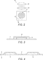
- FIG. 2 is an exploded schematic, part plan, part perspective, view of a force sensitive resistor according to the invention
- FIG. 3 is a side sectional view of the force sensitive resistor of FIG. 2 ;
- FIG. 4 is a sectional view along the line A-A of FIG. 1 ;
- FIG. 5 is a view of a cushioning material for use in the sole of FIG. 1 ;
- FIG. 6 is a sectional view along the line B-B of FIG. 1 ;
- FIG. 7 is an exploded schematic view of a force sensitive resistor according to the prior art.
- FIG. 8 is a top schematic view of a shoe insole comprising a number of force sensitive resistors according to a further embodiment of the invention.
- FIG. 9 is a top schematic view of an alternative shoe insole comprising a number of force sensitive resistors according to the invention.
- the sole (or insole/inner sole) 100 shown in FIG. 1 is formed of upper and lower flexible and stretchable layers 8 , 9 (shown in FIG. 4 ) which are sealed in a water and air tight manner around their outer edge. While the term “sole” is used throughout the description, the described embodiment likewise may apply to an inner sole or insole. In particular, the layers 8 , 9 may be sealed by means of heat or sonic welding.
- the sole 100 may be a separate, removable component, or may be integrated with a shoe.
- the sole 100 is shaped for a human foot and the embodiment of FIG.
- a longitudinal direction X extending from a heel region 22 towards the back of the sole 100 to a toe region 28 towards the front of the sole 100
- a lateral direction Y extending from the inner side to the outer side of the sole 100 . While the sole shown in FIG. 1 is for a right foot, it is appreciated that a mirror version of this sole would be suitable for a left foot. Alternatively, the sole 100 may be usable for either foot by turning the sole 100 over.
- the sole 100 has a midfoot region 24 , a forefoot region 26 and a toe region 28 .
- the heel region 22 supports the user's heel
- the midfoot region 24 supports the user's arch
- the forefoot region 26 supports the user's forefoot
- the toe region 28 supports the user's toes.
- the sole 100 is provided with a number of force sensitive resistors 10 arranged across the sole 100 .
- An exemplary force sensitive resistor 10 is shown in FIG. 2 .
- Conductive ink is printed on the bottom layer 8 in a pattern for a force sensitive resistor 10 .
- This conductive ink forms electrodes 12 , 14 .
- These electrodes 12 , 14 are substantially semi-circular with prongs 13 extending in alternating rows between the electrodes 12 , 14 . This forms a first conductive element.
- the prongs 13 have been omitted from the rest of the Figures for clarity, but they are present in each force sensitive resistor 10 .
- the bottom layer 8 is generally a small section of a larger sheet forming a larger structure.
- the bottom layer 8 may be a fabric, plastic or other flexible material which forms a part of a garment. While the present invention is generally described with respect to a sole 100 , it is appreciated that it may be used with any other garment.
- a garment is generally intended to mean anything which may be worn by a person.
- the garment may be any of a top, vest, trouser, jacket, helmet, inner sole, shoe, under-garment, or any other garment.
- a force sensitive resistor 10 may be provided on the garment.
- the flexible bottom layer 8 may then contact a wearer and/or be subjected to an external impact force, and the force sensitive resistor 10 can determine the force applied by the wearer.
- a spacer ring 18 is provided surrounding the first conductive element.
- a top sensor layer 19 is provided across the spacer ring 18 .
- the top sensor layer 19 is flexible and comprises a second conductive element.
- the top sensor layer is formed from PET.
- the first and second conductive elements may be moved relative to one another in order to vary the resistance of the force sensitive resistor 10 as the user runs.
- the output of the force sensitive resistor 10 may be altered when the lower layer 8 flexes and stretches and hence the results from the resistor 10 cannot be practically used.
- the upper sensor layer 19 is stiffer than the lower layer 8 . This provides the localised region of the lower layer 8 with enhanced strength, on which the first conductive element is printed. In particular, this is achieved by the upper sensor layer 19 having a higher Young's modulus than the lower layer 8 . This locally limits the ease of stretching of the lower layer 8 in the region of the first conductive element within the spacer 18 . As such, the first conductive element may be printed directly on to the lower flexible layer 8 whilst still obtaining useful data.
- the lower layer 8 is provided with printed conductive tracks connected to the electrodes 12 , 14 of the force sensitive resistor 10 . As shown, there may be a single ground track 15 to which each force sensitive resistor 10 is connected. This reduces the space required for the tracks. Each force sensitive resistor 10 is also provided with its own data track 16 .
- the sole is provided with a tab 7 which provides a pathway for the conductive tracks 15 , 16 to an external CPU and control system (not shown).
- the tab 7 is integral with the bottom layer 8 and is likewise flexible and stretchable. While the present figures are shown with an external CPU and control system, this is not necessarily the case, and the CPU and control system may be integral with the sole 100 or provided in another layer designed to be contained within the shoe with the sole 100 .
- the upper and lower flexible layers 8 , 9 of the sole 100 are also sealed in a water and air tight manner across a portion of the central region of the sole 100 .
- FIG. 4 which is a schematic view along A-A as shown on FIG. 1 .
- a compressible material 5 is provided between the outer seal and the central sealed region 3 .
- the compressible material 5 is designed to not seal to either of the upper and lower flexible layers 8 , 9 .
- the layers 8 , 9 should not sonic weld to the compressible material 5 .
- the compressible material 5 is free between the upper and lower flexible layers 8 , 9 .
- the upper and lower flexible layers 8 , 9 are not bonded to the compressible material 5 . This leaves the compressible material 5 free to move in the gap between the layers 8 , 9 .
- the compressible material 5 is substantially continuous, it is held in position by the central sealed region 3 as shown in FIG. 1 .
- the compressible material may be any suitable material.
- it is a foam material, with either an open cell or closed cell arrangement.
- FIG. 5 shows an exemplary open cell foam which may be used with the present invention. High resilience to deformation is necessary to ensure that the sole 100 is not permanently deformed in use.
- the material 5 may form the main support material of the sole 100 , or an additional cushioning material may also be provided for enhanced comfort.
- the material 5 is selected to have a higher melting point than the material of the first and second layers 8 , 9 such that the layers 8 , 9 will seal to one another around the material 5 without sealing to the material 5 .
- the material 5 may be provided across multiple force sensitive resistors 10 . That is, the material 5 may be shared by a plurality of force sensitive resistors 10 .
- the material 5 is provided with cut-away sections substantially aligned with the force sensitive resistors 10 .
- these cut-away sections may be formed such that the material 5 substantially surrounds the force sensitive resistor 10 .
- the material 5 may then not have any overlap with the force sensitive resistor 10 .
- Prior art force sensitive resistors 50 as shown in FIG. 7 which are formed of first conductive element 51 , spacer 53 and second conductive element 55 .
- the spacer 53 is provided with a vent pathway 57 extending from the spacer chamber 58 extending from the spacer chamber 58 .
- the spacer chamber 58 is provided between the conductive elements.
- vent pathway 57 must be provided from the force sensitive resistor 50 to the atmosphere outside of the sole 100 . While efforts are made to minimise these vent pathways, they represent pathways via which moisture may ingress and damage the sole 100 .
- FIG. 9 shows an alternative embodiment of a sole 1 .
- the wiring of the earlier embodiments is not shown in from this Figure for ease of understanding.
- the wiring of this embodiment is substantially the same as described with the other embodiments.
- the compressible material 5 does extend generally across the sole but instead is concentrated in regions around the force sensitive resistors 10 in circular regions 92 surrounding each force sensitive resistor. As the compressible material 5 has a higher melting point than the material of the sole, a seal 98 will be formed around the shape of the compressible material 5 .
- connecting portions 94 of compressible material 5 join the circular sections 92 to form a continuous region of compressible material 5 .
- the circular sections 92 may have some degree of overlap 96 .
- the compressible material 5 is continuous across all of the force sensitive resistors.
- particular regions may each have their own discrete regions of compressible material 5 .
- each force sensitive resistor 10 may have its own discrete sealed section of compressible material 5 .
- the toe and forefoot regions 28 , 26 may each have their own discrete region of compressible material 5
- the force sensitive resistors 10 in the heel and midfoot regions 22 , 24 may be in individual discrete sealed sections of compressible material.
- each region 22 , 24 , 26 , 28 comprises an individual sensing area comprising a plurality of force sensitive resistors 10 .
- These force sensitive resistors 10 are generally similar in shape to one another, in that they are each substantially circular.
- a row of force sensitive resistors 10 extending laterally Y across the sole 100 are provided.
- each row comprises five force sensitive resistors arranged to acquire data regarding each toe and corresponding toe knuckle.
- FIG. 8 an arrangement such as that shown in FIG. 8 may be provided. As shown, the innermost three force sensitive resistors 10 are provided as in FIG. 1 . However, instead of two separate outer force sensitive resistors 10 , a single force sensitive resistor 40 is provided. This force sensitive resistor 40 is elongated in the lateral direction Y to cover the outer part of the toe and forefoot regions 28 , 26 . This elongated force sensitive resistor 40 is substantially rectangular with rounded ends in FIG. 8 .
- the force sensitive resistor 40 is provided with electrodes 42 , 44 and functions as the circular force sensitive resistors 10 described above. It has been identified that the data from the individual outer toes is not of as much interest as the inner regions. Accordingly, the data from the outermost toes can be combined while still being useful for analytics.
- each row has two force sensitive resistors 10 in each of the heel and midfoot regions 22 , 24 .
Abstract
Description
Claims (11)
Applications Claiming Priority (2)
| Application Number | Priority Date | Filing Date | Title |
|---|---|---|---|
| GB1710444.9 | 2017-06-29 | ||
| GB1710444.9A GB2563908A (en) | 2017-06-29 | 2017-06-29 | A force sensitive resistor |
Publications (2)
| Publication Number | Publication Date |
|---|---|
| US20190003907A1 US20190003907A1 (en) | 2019-01-03 |
| US10876910B2 true US10876910B2 (en) | 2020-12-29 |
Family
ID=59592719
Family Applications (1)
| Application Number | Title | Priority Date | Filing Date |
|---|---|---|---|
| US16/021,933 Active 2039-06-08 US10876910B2 (en) | 2017-06-29 | 2018-06-28 | Force sensitive resistor |
Country Status (4)
| Country | Link |
|---|---|
| US (1) | US10876910B2 (en) |
| EP (1) | EP3420836A1 (en) |
| CN (1) | CN109211445A (en) |
| GB (1) | GB2563908A (en) |
Families Citing this family (5)
| Publication number | Priority date | Publication date | Assignee | Title |
|---|---|---|---|---|
| WO2017204514A1 (en) * | 2016-05-23 | 2017-11-30 | 엘지이노텍 주식회사 | Pressure detection sensor and pressure detection insole including same |
| US10890497B2 (en) * | 2018-07-25 | 2021-01-12 | Medic, Inc. | Active pressure sensing toilet gasket and methods of use |
| JP7232937B2 (en) * | 2019-05-06 | 2023-03-03 | センモーション ゲーエムベーハー | Sensor element, sensor arrangement, sensor system and method for detecting force between foot and supporting surface |
| CN111713800B (en) * | 2020-07-01 | 2022-03-11 | 华尔科技集团股份有限公司 | Pressure sensor and manufacturing method thereof |
| US11930886B2 (en) * | 2020-10-07 | 2024-03-19 | Niameh Freeman | Footwear insole with electrical stimulation |
Citations (8)
| Publication number | Priority date | Publication date | Assignee | Title |
|---|---|---|---|---|
| US4314227A (en) | 1979-09-24 | 1982-02-02 | Eventoff Franklin Neal | Electronic pressure sensitive transducer apparatus |
| US5421213A (en) * | 1990-10-12 | 1995-06-06 | Okada; Kazuhiro | Multi-dimensional force detector |
| US20040000195A1 (en) | 2002-06-27 | 2004-01-01 | Kenichi Yanai | Pressure sensor |
| US20060065060A1 (en) * | 2004-09-28 | 2006-03-30 | Pentax Corporation | Pressure detecting mat and antidecubitus system provided with the same |
| WO2009075403A1 (en) | 2007-12-10 | 2009-06-18 | Korea Research Institute Of Standards And Science | High-temperature tactile sensor and method of manufacturing the same |
| US20120291563A1 (en) * | 2008-06-13 | 2012-11-22 | Nike, Inc. | Footwear Having Sensor System |
| US20130098162A1 (en) | 2011-10-21 | 2013-04-25 | Jin-Chern Chiou | Pressure measurement member |
| US20140090488A1 (en) | 2012-09-29 | 2014-04-03 | Stryker Corporation | Flexible Piezocapacitive And Piezoresistive Force And Pressure Sensors |
Family Cites Families (1)
| Publication number | Priority date | Publication date | Assignee | Title |
|---|---|---|---|---|
| JP6164745B2 (en) * | 2012-04-18 | 2017-07-19 | 有限会社モミックスジャパン | Body pressure sensing switch and feedback system including the same |
-
2017
- 2017-06-29 GB GB1710444.9A patent/GB2563908A/en not_active Withdrawn
-
2018
- 2018-06-11 EP EP18177103.1A patent/EP3420836A1/en not_active Withdrawn
- 2018-06-28 US US16/021,933 patent/US10876910B2/en active Active
- 2018-06-29 CN CN201810694158.1A patent/CN109211445A/en active Pending
Patent Citations (9)
| Publication number | Priority date | Publication date | Assignee | Title |
|---|---|---|---|---|
| US4314227A (en) | 1979-09-24 | 1982-02-02 | Eventoff Franklin Neal | Electronic pressure sensitive transducer apparatus |
| US4314227B1 (en) | 1979-09-24 | 1989-01-24 | ||
| US5421213A (en) * | 1990-10-12 | 1995-06-06 | Okada; Kazuhiro | Multi-dimensional force detector |
| US20040000195A1 (en) | 2002-06-27 | 2004-01-01 | Kenichi Yanai | Pressure sensor |
| US20060065060A1 (en) * | 2004-09-28 | 2006-03-30 | Pentax Corporation | Pressure detecting mat and antidecubitus system provided with the same |
| WO2009075403A1 (en) | 2007-12-10 | 2009-06-18 | Korea Research Institute Of Standards And Science | High-temperature tactile sensor and method of manufacturing the same |
| US20120291563A1 (en) * | 2008-06-13 | 2012-11-22 | Nike, Inc. | Footwear Having Sensor System |
| US20130098162A1 (en) | 2011-10-21 | 2013-04-25 | Jin-Chern Chiou | Pressure measurement member |
| US20140090488A1 (en) | 2012-09-29 | 2014-04-03 | Stryker Corporation | Flexible Piezocapacitive And Piezoresistive Force And Pressure Sensors |
Non-Patent Citations (1)
| Title |
|---|
| Intellectual Property Office (The United Kingdom), Search Report issued in corresponding Application No. GB1710444.9, dated Dec. 18, 2017. |
Also Published As
| Publication number | Publication date |
|---|---|
| US20190003907A1 (en) | 2019-01-03 |
| CN109211445A (en) | 2019-01-15 |
| GB201710444D0 (en) | 2017-08-16 |
| GB2563908A (en) | 2019-01-02 |
| EP3420836A1 (en) | 2019-01-02 |
Similar Documents
| Publication | Publication Date | Title |
|---|---|---|
| US10876910B2 (en) | Force sensitive resistor | |
| US11064758B2 (en) | Sole or inner sole | |
| US10753811B2 (en) | Force sensitive resistor for garments and footwear | |
| EP3068252B1 (en) | Method of making an article with coloring layer and control surface layer | |
| JP6837441B2 (en) | Multilayer structure for capacitive pressure sensing | |
| US10222283B2 (en) | Systems and methods of providing automated feedback to a user using a shoe insole assembly | |
| US20200146390A1 (en) | Footwear | |
| KR101609839B1 (en) | Footwear having sensor system | |
| CN108366645B (en) | Electrorheological fluid structures with strain relief elements and methods of manufacture | |
| EP3235428B1 (en) | Flexible pressure mapping device and system for monitoring pressure | |
| US20190094088A1 (en) | Sensor assemblies; sensor-enabled garments and objects; devices and systems for data collection | |
| US20040261294A1 (en) | Shoe insole | |
| TW201717796A (en) | Electronic sensor system for use with footwear | |
| WO2019076461A1 (en) | Insole with sensors | |
| EP3054803B1 (en) | Article of footwear having a sole structure | |
| WO2017185050A1 (en) | Sensor assemblies; sensor-enabled garments and objects; devices and systems for data collection | |
| US20170105475A1 (en) | Orthopedic insole | |
| KR102248967B1 (en) | Smart insole | |
| EP3404388B1 (en) | A sensor pad | |
| JP7476860B2 (en) | Detection device and footwear | |
| KR20210113360A (en) | Load sensing device for articles of footwear | |
| KR101949811B1 (en) | Shoes | |
| CN115886391A (en) | Intelligent running shoe | |
| JP2022183559A (en) | detector |
Legal Events
| Date | Code | Title | Description |
|---|---|---|---|
| AS | Assignment |
Owner name: IMPACT TECH LABS AG, SWITZERLAND Free format text: ASSIGNMENT OF ASSIGNORS INTEREST;ASSIGNOR:IMPACT TECH LABS LIMITED;REEL/FRAME:046230/0637 Effective date: 20180508 |
|
| FEPP | Fee payment procedure |
Free format text: ENTITY STATUS SET TO UNDISCOUNTED (ORIGINAL EVENT CODE: BIG.); ENTITY STATUS OF PATENT OWNER: SMALL ENTITY |
|
| FEPP | Fee payment procedure |
Free format text: ENTITY STATUS SET TO SMALL (ORIGINAL EVENT CODE: SMAL); ENTITY STATUS OF PATENT OWNER: SMALL ENTITY |
|
| STPP | Information on status: patent application and granting procedure in general |
Free format text: APPLICATION DISPATCHED FROM PREEXAM, NOT YET DOCKETED |
|
| AS | Assignment |
Owner name: NURVV LIMITED, GREAT BRITAIN Free format text: ASSIGNMENT OF ASSIGNORS INTEREST;ASSIGNOR:IMPACT TECH LABS AG;REEL/FRAME:048013/0816 Effective date: 20190108 |
|
| STPP | Information on status: patent application and granting procedure in general |
Free format text: DOCKETED NEW CASE - READY FOR EXAMINATION |
|
| AS | Assignment |
Owner name: NURVV LIMITED, GREAT BRITAIN Free format text: ASSIGNMENT OF ASSIGNORS INTEREST;ASSIGNORS:DERVISH, KEMAL;GEVA, HAIM;ROBERTS, JASON LLOYD;AND OTHERS;SIGNING DATES FROM 20190905 TO 20190913;REEL/FRAME:050418/0008 |
|
| STPP | Information on status: patent application and granting procedure in general |
Free format text: PUBLICATIONS -- ISSUE FEE PAYMENT RECEIVED |
|
| STCF | Information on status: patent grant |
Free format text: PATENTED CASE |
|
| AS | Assignment |
Owner name: SILICON VALLEY BANK, AS ADMINISTRATIVE AGENT AND COLLATERAL AGENT, CALIFORNIA Free format text: SECURITY INTEREST;ASSIGNORS:NURVV INC.;NURVV LIMITED;REEL/FRAME:055756/0695 Effective date: 20210329 |
|
| AS | Assignment |
Owner name: IL2 (2018) S.A.R.L., ENGLAND Free format text: SECURITY INTEREST;ASSIGNORS:NURVV INC.;NURVV LIMITED;REEL/FRAME:058399/0366 Effective date: 20211215 |
|
| AS | Assignment |
Owner name: NURVV LIMITED, UNITED KINGDOM Free format text: RELEASE BY SECURED PARTY;ASSIGNOR:IL2 (2018) S.A.R.L;REEL/FRAME:065829/0812 Effective date: 20230915 Owner name: NURVV LIMITED, UNITED KINGDOM Free format text: RELEASE BY SECURED PARTY;ASSIGNOR:SILICON VALLEY BANK;REEL/FRAME:065829/0505 Effective date: 20230915 |
|
| AS | Assignment |
Owner name: DIGITAL VITALITY LIMITED, UNITED KINGDOM Free format text: ASSIGNMENT OF ASSIGNORS INTEREST;ASSIGNOR:NURVV LIMITED;REEL/FRAME:066141/0841 Effective date: 20230915 |