US10876338B2 - Door glass assembly for vehicle - Google Patents
Door glass assembly for vehicle Download PDFInfo
- Publication number
- US10876338B2 US10876338B2 US16/196,346 US201816196346A US10876338B2 US 10876338 B2 US10876338 B2 US 10876338B2 US 201816196346 A US201816196346 A US 201816196346A US 10876338 B2 US10876338 B2 US 10876338B2
- Authority
- US
- United States
- Prior art keywords
- section
- door glass
- rail section
- fixed wall
- guide rail
- Prior art date
- Legal status (The legal status is an assumption and is not a legal conclusion. Google has not performed a legal analysis and makes no representation as to the accuracy of the status listed.)
- Active, expires
Links
- 239000011521 glass Substances 0.000 title claims abstract description 136
- 238000007789 sealing Methods 0.000 claims description 3
- 238000003466 welding Methods 0.000 description 8
- 230000008901 benefit Effects 0.000 description 2
- 238000004519 manufacturing process Methods 0.000 description 2
- 238000000034 method Methods 0.000 description 2
- 230000005540 biological transmission Effects 0.000 description 1
- 230000000593 degrading effect Effects 0.000 description 1
- 239000000945 filler Substances 0.000 description 1
- 239000002184 metal Substances 0.000 description 1
- 238000005192 partition Methods 0.000 description 1
- 238000003860 storage Methods 0.000 description 1
Images


Classifications
-
- E—FIXED CONSTRUCTIONS
- E05—LOCKS; KEYS; WINDOW OR DOOR FITTINGS; SAFES
- E05D—HINGES OR SUSPENSION DEVICES FOR DOORS, WINDOWS OR WINGS
- E05D15/00—Suspension arrangements for wings
- E05D15/06—Suspension arrangements for wings for wings sliding horizontally more or less in their own plane
- E05D15/0621—Details, e.g. suspension or supporting guides
-
- B—PERFORMING OPERATIONS; TRANSPORTING
- B60—VEHICLES IN GENERAL
- B60J—WINDOWS, WINDSCREENS, NON-FIXED ROOFS, DOORS, OR SIMILAR DEVICES FOR VEHICLES; REMOVABLE EXTERNAL PROTECTIVE COVERINGS SPECIALLY ADAPTED FOR VEHICLES
- B60J5/00—Doors
- B60J5/04—Doors arranged at the vehicle sides
- B60J5/0401—Upper door structure
-
- B—PERFORMING OPERATIONS; TRANSPORTING
- B60—VEHICLES IN GENERAL
- B60J—WINDOWS, WINDSCREENS, NON-FIXED ROOFS, DOORS, OR SIMILAR DEVICES FOR VEHICLES; REMOVABLE EXTERNAL PROTECTIVE COVERINGS SPECIALLY ADAPTED FOR VEHICLES
- B60J1/00—Windows; Windscreens; Accessories therefor
- B60J1/08—Windows; Windscreens; Accessories therefor arranged at vehicle sides
- B60J1/12—Windows; Windscreens; Accessories therefor arranged at vehicle sides adjustable
- B60J1/16—Windows; Windscreens; Accessories therefor arranged at vehicle sides adjustable slidable
-
- B—PERFORMING OPERATIONS; TRANSPORTING
- B60—VEHICLES IN GENERAL
- B60J—WINDOWS, WINDSCREENS, NON-FIXED ROOFS, DOORS, OR SIMILAR DEVICES FOR VEHICLES; REMOVABLE EXTERNAL PROTECTIVE COVERINGS SPECIALLY ADAPTED FOR VEHICLES
- B60J1/00—Windows; Windscreens; Accessories therefor
- B60J1/08—Windows; Windscreens; Accessories therefor arranged at vehicle sides
-
- B—PERFORMING OPERATIONS; TRANSPORTING
- B60—VEHICLES IN GENERAL
- B60J—WINDOWS, WINDSCREENS, NON-FIXED ROOFS, DOORS, OR SIMILAR DEVICES FOR VEHICLES; REMOVABLE EXTERNAL PROTECTIVE COVERINGS SPECIALLY ADAPTED FOR VEHICLES
- B60J10/00—Sealing arrangements
- B60J10/30—Sealing arrangements characterised by the fastening means
-
- B—PERFORMING OPERATIONS; TRANSPORTING
- B60—VEHICLES IN GENERAL
- B60J—WINDOWS, WINDSCREENS, NON-FIXED ROOFS, DOORS, OR SIMILAR DEVICES FOR VEHICLES; REMOVABLE EXTERNAL PROTECTIVE COVERINGS SPECIALLY ADAPTED FOR VEHICLES
- B60J10/00—Sealing arrangements
- B60J10/70—Sealing arrangements specially adapted for windows or windscreens
- B60J10/74—Sealing arrangements specially adapted for windows or windscreens for sliding window panes, e.g. sash guides
- B60J10/77—Sealing arrangements specially adapted for windows or windscreens for sliding window panes, e.g. sash guides for sashless windows, i.e. for frameless windows forming a seal directly with the vehicle body
-
- B—PERFORMING OPERATIONS; TRANSPORTING
- B60—VEHICLES IN GENERAL
- B60J—WINDOWS, WINDSCREENS, NON-FIXED ROOFS, DOORS, OR SIMILAR DEVICES FOR VEHICLES; REMOVABLE EXTERNAL PROTECTIVE COVERINGS SPECIALLY ADAPTED FOR VEHICLES
- B60J10/00—Sealing arrangements
- B60J10/70—Sealing arrangements specially adapted for windows or windscreens
- B60J10/74—Sealing arrangements specially adapted for windows or windscreens for sliding window panes, e.g. sash guides
- B60J10/79—Sealing arrangements specially adapted for windows or windscreens for sliding window panes, e.g. sash guides for flush-glass windows, i.e. for windows flush with the vehicle body or the window frame
-
- E—FIXED CONSTRUCTIONS
- E05—LOCKS; KEYS; WINDOW OR DOOR FITTINGS; SAFES
- E05Y—INDEXING SCHEME ASSOCIATED WITH SUBCLASSES E05D AND E05F, RELATING TO CONSTRUCTION ELEMENTS, ELECTRIC CONTROL, POWER SUPPLY, POWER SIGNAL OR TRANSMISSION, USER INTERFACES, MOUNTING OR COUPLING, DETAILS, ACCESSORIES, AUXILIARY OPERATIONS NOT OTHERWISE PROVIDED FOR, APPLICATION THEREOF
- E05Y2900/00—Application of doors, windows, wings or fittings thereof
- E05Y2900/50—Application of doors, windows, wings or fittings thereof for vehicles
- E05Y2900/53—Type of wing
- E05Y2900/55—Windows
Definitions
- the present disclosure relates to a door glass assembly for a vehicle.
- Side doors of a passenger vehicle include a door frame having a window opening, a door glass which is movable in a vertical direction to open and close the window opening of the door frame, and a door regulator moving the door glass in the vertical direction.
- the side door of the vehicle has a stepped portion between an outer surface of the door frame and an outer surface of the door glass due to a roof of a vehicle body, a weatherstrip belt, a filler of the vehicle body, etc., so that the door glass is recessed relative to the door frame.
- the stepped portion may degrade the exterior styling of the vehicle, and may cause the generation of turbulence, wind noise, and the like while the vehicle is travelling, thereby degrading aerodynamic performance and noise vibration harshness (NVH) performance.
- NSH noise vibration harshness
- a door panel of a typical side door has a sufficient space for receiving a door glass and a door regulator, the width of the door panel is increased, and thus the interior space of the vehicle is relatively narrowed.
- An aspect of the present disclosure provides a door glass assembly for a vehicle, allowing a flush-glass arrangement to minimize parts and guiding a door glass to move in a horizontal direction, thereby maximizing an interior space of the vehicle.
- a door glass assembly for a vehicle may include: a door panel; a fixed wall which is fixedly connected to a top end of the door panel; an upper guide rail which is extended along a top edge of the fixed wall; a lower guide rail which is extended along a bottom edge of the fixed wall; and a door glass which is movable in a horizontal direction with respect to the fixed wall, and is guided to move along the upper guide rail and the lower guide rail in the horizontal direction, wherein the door glass may open and close a portion of a door opening defined by the door panel and the fixed wall, and an external surface of the door glass may be flush with an external surface of the fixed wall when the door glass is in a closed position to close the door opening.
- the upper guide rail may include a first upper rail section which is spaced apart from the fixed wall toward an interior space of the vehicle, a second upper rail section which is offset from the first upper rail section toward the interior space of the vehicle, and a third upper rail section connecting the first upper rail section and the second upper rail section
- the lower guide rail may include a first lower rail section which is spaced apart from the fixed wall toward the interior space of the vehicle, a second lower rail section which is offset from the first lower rail section toward the interior space of the vehicle, and a third lower rail section connecting the first lower rail section and the second lower rail section.
- the door glass assembly may further include: a vertical guide rail attached to an internal surface of the door glass; and an upper guide shaft connected between the upper guide rail and the vertical guide rail, wherein the upper guide shaft may have a first roller which is guided along the upper guide rail, and a second roller which is guided along the vertical guide rail.
- the door glass assembly may further include a lower guide shaft connected between the lower guide rail and an internal surface of a bottom end of the door glass, wherein the lower guide shaft may have a third roller which is guided along the lower guide rail.
- the third upper rail section may be extended from a front end of the first upper rail section in an oblique direction, and the second upper rail section may be extended from a front end of the third upper rail section toward the front of the vehicle.
- the third upper rail section and the second upper rail section may protrude from a front edge of the fixed wall toward the front of the vehicle.
- the third lower rail section may be extended from a front end of the first lower rail section in an oblique direction, and the second lower rail section may be extended from a front end of the third lower rail section toward the front of the vehicle.
- the third lower rail section and the second lower rail section may protrude from a front edge of the fixed wall toward the front of the vehicle.
- the door glass assembly may further include: an upper support provided on a top end of the fixed wall, and supporting the upper guide rail; and a lower support provided on a bottom end of the fixed wall, and supporting the lower guide rail.
- the upper support may include a first upper support section supporting the first upper rail section, a second upper support section supporting the second upper rail section, and a third upper support section supporting the third upper rail section.
- the door glass assembly may further include: an upper flat section connected to a top end of the upper support; and at least one weatherstrip disposed between the upper flat section and a top edge of the door glass, wherein the weatherstrip may seal the top edge of the door glass.
- the lower support may include a first lower support section supporting the first lower rail section, a second lower support section supporting the second lower rail section, and a third lower support section supporting the third lower rail section.
- the door glass assembly may further include: a lower flat section connected to a bottom end of the lower support; and at least one weatherstrip disposed between the lower flat section and a bottom edge of the door glass, wherein the weatherstrip may seal the bottom edge of the door glass.
- An interior trim may be fixedly connected to an internal surface of a front edge of the fixed wall, and the interior trim may have at least one weatherstrip sealing a rear edge of the door glass.
- FIG. 1 illustrates a side view of a vehicle having a door glass assembly for a vehicle according to an embodiment of the present disclosure, in a state in which the door glass assembly closes a door opening of the vehicle;
- FIG. 2 illustrates a perspective view of a door glass assembly for a vehicle according to an embodiment of the present disclosure
- FIG. 3 illustrates a cross-sectional view taken along line A-A of FIG. 1 ;
- FIG. 4 illustrates a cross-sectional view taken along line C-C of FIG. 3 ;
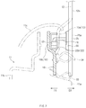
- FIG. 5 illustrates a cross-sectional view taken along line D-D of FIG. 3 ;
- FIG. 6 illustrates a cross-sectional view taken along line B-B of FIG. 1 ;
- FIG. 7 illustrates a cross-sectional view taken along line E-E of FIG. 6 ;
- FIG. 8 illustrates a cross-sectional view taken along line F-F of FIG. 6 ;
- FIG. 9 illustrates a side view of a vehicle having a door glass assembly for a vehicle according to an embodiment of the present disclosure, in a state in which a door glass starts to open a portion of a door opening;
- FIG. 10 illustrates a cross-sectional view taken along line G-G of FIG. 9 ;
- FIG. 11 illustrates a side view of a vehicle having a door glass assembly for a vehicle according to an embodiment of the present disclosure, in a state in which a door glass is moved to a fully opened position to fully open a portion of a door opening;
- FIG. 12 illustrates a cross-sectional view taken along line H-H of FIG. 11 .
- the door glass In a flush-glass arrangement, the door glass is flush with the door frame or the outer surface of the vehicle. In the flush-glass arrangement, however, it is required to maintain a gap between the door frame and the door glass uniformly and to secure the vertical movement of the door glass, so that the door frame structure may become complicated. Thus, expensive parts may be additionally required, and the assembly process may be difficult, resulting in an increase in manufacturing costs.
- a door glass assembly 10 for a vehicle may include a door panel 11 , a fixed wall 12 which is fixedly connected to a top end of the door panel 11 , and a door glass 25 which is movable in a horizontal direction with respect to the fixed wall 12 .
- the door panel 11 may have an outer panel 11 a , an inner panel 11 b , and a door trim 11 c.
- a bottom end of the fixed wall 12 may be fixedly connected to the outer panel 11 a of the door panel 11 .
- the door glass assembly 10 may open and close a door opening 2 of a vehicle 1 .
- a portion of the door opening 2 may be opened and closed by the door glass 25 .
- the portion of the door opening 2 to be opened and closed by the door glass 25 may be defined by the door panel 11 and the fixed wall 12 .
- the portion of the door opening 2 may be defined by a top edge of the door panel 11 and a front edge of the fixed wall 12 .
- the opening may be defined by the top edge of the door panel, a front edge of the fixed wall 12 and a portion of a vehicle body.
- the door glass 25 may be movable between an opened position in which the portion of the door opening 2 is opened (see FIG. 11 ) and a closed position in which the portion of the door opening 2 is closed (see FIG. 1 ).
- the door glass 25 may be mechanically connected to a drive mechanism 50 , and the door glass 25 may be moved horizontally by the drive mechanism 50 to open and close the portion of the door opening 2 .
- the drive mechanism 50 may have a drive motor and a power transmission mechanism to move the door glass 25 in the horizontal direction.
- the drive mechanism 50 may be disposed inside the door panel 11 adjacent to the bottom end of the fixed wall 12 , and thus the door panel 11 may be made thinner than a typical one.
- the fixed wall 12 may partition an interior space and an exterior space of the vehicle.
- an upper guide rail 21 may be fixedly connected to or coupled to a top end of the fixed wall 12 , and the upper guide rail 21 may extend along a top edge of the fixed wall 12 .
- a lower guide rail 22 may be fixedly connected to the bottom end of the fixed wall 12 , and the lower guide rail 22 may extend along a bottom edge of the fixed wall 12 .
- the upper guide rail 21 and the lower guide rail 22 may guide the horizontal movement of the door glass 25 .
- the top edge of the fixed wall 12 may have a curved section 12 f on the rear thereof, and the upper guide rail 21 may have a curved section 21 f corresponding to the curved section 12 f of the fixed wall 12 .
- an upper support 13 may be provided on the top end of the fixed wall 12 , and the upper support 13 may support the upper guide rail 21 .
- the upper guide rail 21 may be connected to the upper support 13 by welding, fasteners, or the like, so that the upper guide rail 21 may be supported by the upper support 13 .
- the upper support 13 and the upper guide rail 21 may be spaced apart from an internal surface 12 b of the fixed wall 12 toward the interior space of the vehicle (see the direction of arrow IN).
- the upper guide rail 21 may include a first upper rail section 21 a , a second upper rail section 21 b and a third upper rail section 21 c .
- the first upper rail section 21 a is spaced apart from the fixed wall 12 toward the interior space of the vehicle.
- the second upper rail section 21 b is offset from the first upper rail section 21 a toward the interior space of the vehicle.
- the third upper rail section 21 c connecting the first upper rail section 21 a and the second upper rail section 21 b .
- the first upper rail section 21 a may extend along the top edge of the fixed wall 12
- the second upper rail section 21 b may be connected to the first upper rail section 21 a through the third upper rail section 21 c .
- the third upper rail section 21 c may extend between the first upper rail section 21 a and the second upper rail section 21 b in an oblique direction.
- the first upper rail section 21 a is parallel to the second upper rail section 21 b
- the third upper rail section 21 c is inclined with respect to the first and second upper rail sections.
- the third upper rail section 21 c may extend from a front end of the first upper rail section 21 a in the oblique direction, and the second upper rail section 21 b may extend from a front end of the third upper rail section 21 c toward the front of the vehicle.
- the third upper rail section 21 c and the second upper rail section 21 b may protrude from a front end 12 g of the fixed wall 12 toward the front of the vehicle (see the direction of arrow FR in FIG. 3 ).
- FIG. 3 illustrates the third upper rail section 21 c and the second upper rail section 21 b
- a front edge of the first upper rail section 21 a may be adjacent to a rear edge of the door glass 25 , and an external surface 25 a of the door glass 25 may be flush with an external surface 12 a of the fixed wall 12 .
- the second upper rail section 21 b may be offset from the fixed wall 12 toward the interior space of the vehicle, and protrude from the front end 12 g of the fixed wall 12 toward the front of the vehicle, so that a simple, compact flush-glass arrangement may be effectively achieved.
- the upper support 13 may include a first upper support section 13 a supporting the first upper rail section 21 a , a second upper support section 13 b supporting the second upper rail section 21 b , and a third upper support section 13 c supporting the third upper rail section 21 c .
- the first upper support section 13 a may extend along the top edge of the fixed wall 12
- the second upper support section 13 b may be connected to the first upper support section 13 a through the third upper support section 13 c
- the third upper support section 13 c may extend between the first upper support section 13 a and the second upper support section 13 b in the oblique direction.
- the first upper rail section 21 a may be connected to the first upper support section 13 a by welding, fasteners, or the like.
- the second upper rail section 21 b may be connected to the second upper support section 13 b by welding, fasteners, or the like. As illustrated in FIG. 5 , the second upper support section 13 b may be integrally connected to the top end of the fixed wall 12 through an inclined portion 12 c.
- an upper flat section 14 may be connected or coupled to a top end of the upper support 13 , and the upper flat section 14 may extend along the top edge of the fixed wall 12 .
- the upper flat section 14 may be integrally connected to the top end of the first upper support section 13 a , the top end of the second upper support section 13 b , and the top end of the third upper support section 13 c.
- the upper flat section 14 may be adjacent to an interior headliner 6 and a roof side outer 5 of the vehicle.
- a first weatherstrip 31 and a second weatherstrip 32 may be disposed between the upper flat section 14 and a top edge of the door glass 25 .
- the first weatherstrip 31 may be mounted on the roof side outer 5 of the vehicle, and the second weatherstrip 32 may be mounted on the upper flat section 14 .
- the first and second weatherstrips 31 and 32 may seal the top edge of the door glass 25 .
- the third upper rail section 21 c may be connected to the third upper support section 13 c by welding, fasteners, or the like.
- the door glass 25 may have the external surface 25 a facing the exterior space of the vehicle (see the direction of arrow EX) and an internal surface 25 b facing the interior space of the vehicle (see the direction of arrow IN).
- a vertical guide rail 43 which vertically extends may be attached to the internal surface 25 b of the door glass 25 .
- a top end of the door glass 25 may move along the upper guide rail 21 and the vertical guide rail 43 , and an upper guide shaft 45 may be connected between the upper guide rail 21 and the vertical guide rail 43 .
- a first roller 51 may be rotatably mounted on one end of the upper guide shaft 45 , and an axis of rotation of the first roller 51 may be orthogonal to an axis of the upper guide shaft 45 .
- the first roller 51 may roll along the upper guide rail 21 .
- a second roller 52 may be rotatably mounted on the other end of the upper guide shaft 45 , and an axis of rotation of the second roller 52 may be coincident with or parallel to the axis of the upper guide shaft 45 .
- the second roller 52 may roll and move along the vertical guide rail 43 .
- the second roller 52 of the upper guide shaft 45 may move along the vertical guide rail 43 so that the door glass 25 may be moved in the horizontal direction.
- the upper guide shaft 45 may move along the upper guide rail 21 in the horizontal direction while moving along the vertical guide rail 43 in the vertical direction, so that the door glass 25 may be stably moved in the horizontal direction regardless of the curvature of the curved section 21 f of the upper guide rail 21 .
- a lower support 15 may be provided at the bottom end of the fixed wall 12 , and the lower support 15 may support the lower guide rail 22 .
- the lower guide rail 22 may be connected to the lower support 15 by welding, fasteners, or the like, so that the lower guide rail 22 may be supported by the lower support 15 .
- the lower guide rail 22 may include a first lower rail section 22 a which is spaced apart from the fixed wall 12 toward the interior space of the vehicle, a second lower rail section 22 b which is offset from the first lower rail section 22 a toward the interior space of the vehicle, and a third lower rail section 22 c connecting the first lower rail section 22 a and the second lower rail section 22 b .
- the first lower rail section 22 a may extend along a longitudinal direction of the fixed wall 12
- the second lower rail section 22 b may be connected to the first lower rail section 22 a through the third lower rail section 22 c .
- the third lower rail section 22 c may extends between the first lower rail section 22 a and the second lower rail section 22 b in an oblique direction.
- the first lower rail section 22 a is parallel to the second lower rail section 22 b
- the third lower rail section 22 c is inclined with respect to the first and second lower rail sections.
- the lower support 15 may include a first lower support section 15 a supporting the first lower rail section 22 a , a second lower support section 15 b supporting the second lower rail section 22 b , and a third lower support section 15 c supporting the third lower rail section 22 c .
- the first lower support section 15 a may extends along the bottom edge of the fixed wall 12
- the second lower support section 15 b may be connected to the first lower support section 15 a through the third lower support section 15 c
- the third lower support section 15 c may extends between the first lower support section 15 a and the second lower support section 15 b in the oblique direction.
- the first lower rail section 22 a may extends along the top edge of the fixed wall 12
- the third lower rail section 22 c may extends from a front end of the first lower rail section 22 a in the oblique direction
- the second lower rail section 22 b may extends from a front end of the third lower rail section 22 c .
- the third lower rail section 22 c and the second lower rail section 22 b may protrude from the front end 12 g of the fixed wall 12 toward the front of the vehicle (see the direction of arrow FR in FIG. 6 ). As illustrated in FIG.
- a front edge of the first lower rail section 22 a may be adjacent to the rear edge of the door glass 25 , and the external surface 25 a of the door glass 25 may be flush with the external surface 12 a of the fixed wall 12 .
- the second lower rail section 22 b may be offset from the fixed wall 12 toward the interior space of the vehicle, and protrude from the front end 12 g of the fixed wall 12 toward the front of the vehicle, so that a simple, compact flush-glass arrangement may be effectively achieved.
- the first lower rail section 22 a may be connected to the first lower support section 15 a by welding, fasteners, or the like.
- the second lower rail section 22 b may be connected to the second lower support section 15 b by welding, fasteners, or the like.
- the second lower support section 15 b may be integrally connected to the bottom end of the fixed wall 12 through an inclined portion 12 d.
- a lower flat section 16 may be connected to a bottom end of the lower support 15 , and the lower flat section 16 may extend along the bottom edge of the fixed wall 12 .
- the lower flat section 16 may be integrally connected to the bottom end of the first lower support section 15 a , the bottom end of the second lower support section 15 b , and the bottom end of the third lower support section 15 c.
- the lower flat section 16 may be adjacent to the outer panel 11 a and the door trim 11 c of the door panel 11 .
- a third weatherstrip 33 and a fourth weatherstrip 34 may be disposed between the lower flat section 16 and a bottom edge of the door glass 25 .
- the third weatherstrip 33 may be mounted on the outer panel 11 a of the door panel 11
- the fourth weatherstrip 34 may be mounted on the lower flat section 16 .
- the third and fourth weatherstrips 33 and may seal the bottom edge of the door glass 25 .
- the fixed wall 12 , the upper and lower supports 13 and 15 and the upper and lower flat sections 14 and 16 may be formed of a single piece metal plate.
- the third lower rail section 22 c may be connected to the third lower support section 15 c by welding, fasteners, or the like.
- a bottom end of the door glass 25 may move along the lower guide rail 22 , and a lower guide shaft 46 may be connected between the lower guide rail 22 and the internal surface 25 b of the bottom end of the door glass 25 .
- a third roller 53 may be rotatably mounted on one end of the lower guide shaft 46 , and an axis of rotation of the third roller 53 may be orthogonal to an axis of the lower guide shaft 46 .
- the third roller 53 may roll along the lower guide rail 22 .
- a fixed bracket 55 may be provided at the other end of the lower guide shaft 46 , and the fixed bracket 55 may be attached to the internal surface 25 b of the bottom end of the door glass 25 , so that the other end of the lower guide shaft 46 may be fixedly connected to the internal surface 25 b of the bottom end of the door glass 25 through the fixed bracket 55 .
- the third roller 53 of the lower guide shaft 46 rolls along the lower guide rail 22 , the bottom end of the door glass 25 may move along the lower guide rail 22 in the horizontal direction.
- the rear edge of the door glass 25 may face the first upper rail section 21 a , and the external surface 25 a of the door glass 25 may be flush with the external surface 12 a of the fixed wall 12 .
- an interior trim 26 may be fixedly connected to the internal surface of the front edge of the fixed wall 12 .
- the interior trim 26 may have a fifth weatherstrip 35 and a sixth weatherstrip 36 sealing the rear edge of the door glass 25 .
- the rear edge of the door glass 25 may be adjacent to the front edge of the fixed wall 12
- the interior trim 26 may be disposed between the rear edge of the door glass 25 and the front edge of the fixed wall 12 .
- the first roller 51 of the upper guide shaft 45 may be positioned on the second upper rail section 21 b of the upper guide rail 21 as illustrated in FIG. 3
- the third roller 53 of the lower guide shaft 46 may be positioned on the second lower rail section 22 b of the lower guide rail 22 as illustrated in FIG. 6 .
- the first roller 51 of the upper guide shaft 45 may be guided along the third upper rail section 21 c of the upper guide rail 21 as illustrated in FIG. 10 , and the door glass 25 may protrude toward the exterior space of the vehicle (see the direction of arrow EX).
- the first roller 51 of the upper guide shaft 45 may be guided along the first upper rail section 21 a of the upper guide rail 21 as illustrated in FIG. 12 , and the door glass 25 may move along the external surface 12 a of the fixed wall 12 .
- the door glass 25 may be guided along the upper guide rail 21 , the vertical guide rail 43 , and the lower guide rail 22 , so that the drive mechanism for moving the door glass 25 may be relatively compact inside the door panel 11 , compared to a corresponding one according to the related art. Since the thickness of the door panel 11 is made thin, the interior space of the vehicle may be increased, and sufficient spaces for displays, storage, and the like, may be secured in the inside of the door panel 11 .
- the second upper rail section 21 b of the upper guide rail 21 and the second lower rail section 22 b of the lower guide rail 22 may be offset from the fixed wall 12 toward the interior space of the vehicle 1 and protrude from the front edge of the fixed wall 12 toward the front of the vehicle, so that a simple, compact flush-glass arrangement may be effectively achieved.
- the exterior styling, aerodynamic performance, and noise vibration harshness (NVH) performance of the vehicle may be improved, and parts such as a door module, a door regulator, a center pillar, and a door frame may be eliminated, so that the manufacturing cost may be reduced.
Landscapes
- Engineering & Computer Science (AREA)
- Mechanical Engineering (AREA)
- Window Of Vehicle (AREA)
Abstract
Description
Claims (19)
Applications Claiming Priority (2)
| Application Number | Priority Date | Filing Date | Title |
|---|---|---|---|
| KR1020180120002A KR102575721B1 (en) | 2018-10-08 | 2018-10-08 | Door glass assembly for vehicle |
| KR10-2018-0120002 | 2018-10-08 |
Publications (2)
| Publication Number | Publication Date |
|---|---|
| US20200109585A1 US20200109585A1 (en) | 2020-04-09 |
| US10876338B2 true US10876338B2 (en) | 2020-12-29 |
Family
ID=70051249
Family Applications (1)
| Application Number | Title | Priority Date | Filing Date |
|---|---|---|---|
| US16/196,346 Active 2039-03-28 US10876338B2 (en) | 2018-10-08 | 2018-11-20 | Door glass assembly for vehicle |
Country Status (3)
| Country | Link |
|---|---|
| US (1) | US10876338B2 (en) |
| KR (1) | KR102575721B1 (en) |
| CN (1) | CN111002800B (en) |
Families Citing this family (4)
| Publication number | Priority date | Publication date | Assignee | Title |
|---|---|---|---|---|
| US20180168382A1 (en) * | 2016-08-31 | 2018-06-21 | Karen Goelst | Cubicle Privacy Curtain Assembly |
| CN111927240B (en) * | 2020-08-07 | 2024-08-23 | 信义汽车玻璃(深圳)有限公司 | Vehicle and sliding window thereof |
| US11317753B1 (en) | 2021-02-04 | 2022-05-03 | Kleenedge, Llc | Partition curtain track system |
| EP4335674B1 (en) * | 2022-09-09 | 2024-11-06 | Nio Technology (Anhui) Co., Ltd | Vehicle door assembly |
Citations (10)
| Publication number | Priority date | Publication date | Assignee | Title |
|---|---|---|---|---|
| US2132422A (en) * | 1937-03-01 | 1938-10-11 | Kannel Charles | Vehicle ventilating means |
| US4158270A (en) * | 1977-02-11 | 1979-06-19 | Regie Nationale Des Usines Renault | Device for driving sliding windows |
| US4177605A (en) * | 1977-02-22 | 1979-12-11 | Regie Nationale Des Usines Renault | Device for driving panels in conveyance, especially horizontally-sliding windows in an automobile |
| US20080060275A1 (en) * | 2006-09-11 | 2008-03-13 | Guardian Industries Corp. | Slider window for pick-up truck, and/or method of making the same |
| US20080100093A1 (en) * | 2006-10-30 | 2008-05-01 | Pilkington North America, Inc. | Vehicle window assembly with horizontal slider |
| US20090183434A1 (en) * | 2006-06-09 | 2009-07-23 | Pilkington Automotive Finland Oy | Vehicle glazing |
| US20090217595A1 (en) * | 2008-02-28 | 2009-09-03 | Rainer Grimm | Sliding window assembly |
| US20110006558A1 (en) * | 2007-12-10 | 2011-01-13 | Advanced Comfort Systems France Sas - Acs France | Device for closing off an opening formed in the bodywork of a vehicle, with a guide element and slide forming a shuttle, and corresponding vehicle |
| US20120167469A1 (en) * | 2009-06-19 | 2012-07-05 | Advanced Comfort Systems France Sas - Acs France | Device for closing off an opening made in a structural element comprising synchronization, and corresponding automobile |
| US9233734B2 (en) * | 2013-05-29 | 2016-01-12 | Taylor Made Group, Llc | Windshield sliding door/window assembly |
Family Cites Families (9)
| Publication number | Priority date | Publication date | Assignee | Title |
|---|---|---|---|---|
| DE4220600A1 (en) * | 1992-06-24 | 1994-01-13 | Josef Weis Plastic Gmbh & Co K | Sliding window arrangement, in particular for aircraft cockpit |
| JP3900167B2 (en) * | 2003-07-09 | 2007-04-04 | トヨタ車体株式会社 | Vehicle sliding window |
| KR100814950B1 (en) * | 2006-08-07 | 2008-03-19 | 대성전기공업 주식회사 | Automatic window opening and closing method for vehicle |
| US7900993B2 (en) * | 2008-01-31 | 2011-03-08 | Fuji Jukogyo Kabushiki Kaisha | Vehicle door sash structure |
| KR101294191B1 (en) * | 2011-12-09 | 2013-08-08 | 현대자동차주식회사 | Flush glass apparatus for vehicle |
| JP5997739B2 (en) * | 2014-09-12 | 2016-09-28 | 本田技研工業株式会社 | Sliding door structure for vehicles |
| CN104608601A (en) * | 2014-11-17 | 2015-05-13 | 中国北车集团大同电力机车有限责任公司 | Locomotive cab movable side window |
| US10145401B2 (en) * | 2017-01-26 | 2018-12-04 | Ford Global Technologies, Llc | Clip for a vehicle door assembly |
| CN107738562B (en) * | 2017-09-25 | 2019-07-16 | 福耀玻璃工业集团股份有限公司 | A kind of sliding window assembly |
-
2018
- 2018-10-08 KR KR1020180120002A patent/KR102575721B1/en active Active
- 2018-11-20 US US16/196,346 patent/US10876338B2/en active Active
- 2018-11-23 CN CN201811408850.XA patent/CN111002800B/en active Active
Patent Citations (12)
| Publication number | Priority date | Publication date | Assignee | Title |
|---|---|---|---|---|
| US2132422A (en) * | 1937-03-01 | 1938-10-11 | Kannel Charles | Vehicle ventilating means |
| US4158270A (en) * | 1977-02-11 | 1979-06-19 | Regie Nationale Des Usines Renault | Device for driving sliding windows |
| US4177605A (en) * | 1977-02-22 | 1979-12-11 | Regie Nationale Des Usines Renault | Device for driving panels in conveyance, especially horizontally-sliding windows in an automobile |
| US20090183434A1 (en) * | 2006-06-09 | 2009-07-23 | Pilkington Automotive Finland Oy | Vehicle glazing |
| US20080060275A1 (en) * | 2006-09-11 | 2008-03-13 | Guardian Industries Corp. | Slider window for pick-up truck, and/or method of making the same |
| US20080100093A1 (en) * | 2006-10-30 | 2008-05-01 | Pilkington North America, Inc. | Vehicle window assembly with horizontal slider |
| US20100071270A1 (en) * | 2006-10-30 | 2010-03-25 | Seiple Shane C | Vehicle window assembly |
| US20110006558A1 (en) * | 2007-12-10 | 2011-01-13 | Advanced Comfort Systems France Sas - Acs France | Device for closing off an opening formed in the bodywork of a vehicle, with a guide element and slide forming a shuttle, and corresponding vehicle |
| US20090217595A1 (en) * | 2008-02-28 | 2009-09-03 | Rainer Grimm | Sliding window assembly |
| US20120167469A1 (en) * | 2009-06-19 | 2012-07-05 | Advanced Comfort Systems France Sas - Acs France | Device for closing off an opening made in a structural element comprising synchronization, and corresponding automobile |
| US8769872B2 (en) * | 2009-06-19 | 2014-07-08 | Advanced Comfort Systems France Sas-Acs France | Device for closing off an opening made in a structural element comprising synchronization, and corresponding automobile |
| US9233734B2 (en) * | 2013-05-29 | 2016-01-12 | Taylor Made Group, Llc | Windshield sliding door/window assembly |
Also Published As
| Publication number | Publication date |
|---|---|
| KR20200040119A (en) | 2020-04-17 |
| CN111002800B (en) | 2024-09-06 |
| KR102575721B1 (en) | 2023-09-07 |
| US20200109585A1 (en) | 2020-04-09 |
| CN111002800A (en) | 2020-04-14 |
Similar Documents
| Publication | Publication Date | Title |
|---|---|---|
| US10876338B2 (en) | Door glass assembly for vehicle | |
| US10549618B2 (en) | Weather strip | |
| EP1325827B1 (en) | A-pillar and roof side section housing a seal for vehicle of sash-less door type | |
| US4089134A (en) | Window guide mechanism for a tight air seal of a vehicle window assembly | |
| RU2602847C2 (en) | Car door (versions) | |
| US6279989B1 (en) | Roof construction for a vehicle | |
| JPH0248221A (en) | Door structure of vehicle | |
| CN108116202B (en) | Mounting structure of glass run for automobile door | |
| US11110782B2 (en) | Automotive door sealing structure | |
| US20170182871A1 (en) | Parting seal and sealing structure of parting portion | |
| US10525800B2 (en) | Vehicle door structure | |
| US8220203B2 (en) | Sliding door tambour close out panel | |
| JPH0336693B2 (en) | ||
| US20230182554A1 (en) | Frameless door for vehicle and method for manufacturing thereof | |
| US12188274B2 (en) | Door hinge device of vehicle | |
| JP2021172185A (en) | Seal material for motor vehicle door | |
| US8807642B2 (en) | Mechanism components integrated into structural sunroof framework | |
| US20210101459A1 (en) | Cover for closing an opening in a vehicle body | |
| US20050279027A1 (en) | Weatherstrip | |
| JP2017210048A (en) | Glass run for vehicle door | |
| JP5906908B2 (en) | Door seal structure | |
| US20210347236A1 (en) | Vehicle roof device | |
| US8807643B2 (en) | Sunroof mechanism linkage with continuous one part guide track | |
| US20250002089A1 (en) | Vehicle a pillar bracket | |
| JPH0517292Y2 (en) |
Legal Events
| Date | Code | Title | Description |
|---|---|---|---|
| AS | Assignment |
Owner name: KIA MOTORS CORPORATION, KOREA, REPUBLIC OF Free format text: ASSIGNMENT OF ASSIGNORS INTEREST;ASSIGNORS:LEE, HYEOK JI;CHOI, SEUNG IL;KIM, JIN RO;REEL/FRAME:047555/0957 Effective date: 20181107 Owner name: HYUNDAI MOTOR COMPANY, KOREA, REPUBLIC OF Free format text: ASSIGNMENT OF ASSIGNORS INTEREST;ASSIGNORS:LEE, HYEOK JI;CHOI, SEUNG IL;KIM, JIN RO;REEL/FRAME:047555/0957 Effective date: 20181107 |
|
| FEPP | Fee payment procedure |
Free format text: ENTITY STATUS SET TO UNDISCOUNTED (ORIGINAL EVENT CODE: BIG.); ENTITY STATUS OF PATENT OWNER: LARGE ENTITY |
|
| STPP | Information on status: patent application and granting procedure in general |
Free format text: RESPONSE TO NON-FINAL OFFICE ACTION ENTERED AND FORWARDED TO EXAMINER |
|
| STPP | Information on status: patent application and granting procedure in general |
Free format text: PUBLICATIONS -- ISSUE FEE PAYMENT RECEIVED |
|
| STCF | Information on status: patent grant |
Free format text: PATENTED CASE |
|
| MAFP | Maintenance fee payment |
Free format text: PAYMENT OF MAINTENANCE FEE, 4TH YEAR, LARGE ENTITY (ORIGINAL EVENT CODE: M1551); ENTITY STATUS OF PATENT OWNER: LARGE ENTITY Year of fee payment: 4 |