US10869485B2 - Automatic table-top machine for kneading and extruding pasta - Google Patents
Automatic table-top machine for kneading and extruding pasta Download PDFInfo
- Publication number
- US10869485B2 US10869485B2 US15/298,622 US201615298622A US10869485B2 US 10869485 B2 US10869485 B2 US 10869485B2 US 201615298622 A US201615298622 A US 201615298622A US 10869485 B2 US10869485 B2 US 10869485B2
- Authority
- US
- United States
- Prior art keywords
- output shaft
- respect
- kneading
- vertical wall
- fixed
- Prior art date
- Legal status (The legal status is an assumption and is not a legal conclusion. Google has not performed a legal analysis and makes no representation as to the accuracy of the status listed.)
- Active, expires
Links
- 238000004898 kneading Methods 0.000 title claims abstract description 24
- 235000015927 pasta Nutrition 0.000 title claims abstract description 19
- 230000005540 biological transmission Effects 0.000 claims abstract description 9
- 230000002787 reinforcement Effects 0.000 claims abstract description 8
- 239000002184 metal Substances 0.000 claims abstract description 4
- 238000001125 extrusion Methods 0.000 claims description 11
- 230000002093 peripheral effect Effects 0.000 claims description 3
- 230000005484 gravity Effects 0.000 description 3
- 230000008878 coupling Effects 0.000 description 2
- 238000010168 coupling process Methods 0.000 description 2
- 238000005859 coupling reaction Methods 0.000 description 2
- 238000012423 maintenance Methods 0.000 description 2
- 230000000284 resting effect Effects 0.000 description 1
- 125000006850 spacer group Chemical group 0.000 description 1
Images


Classifications
-
- A—HUMAN NECESSITIES
- A21—BAKING; EDIBLE DOUGHS
- A21C—MACHINES OR EQUIPMENT FOR MAKING OR PROCESSING DOUGHS; HANDLING BAKED ARTICLES MADE FROM DOUGH
- A21C1/00—Mixing or kneading machines for the preparation of dough
- A21C1/06—Mixing or kneading machines for the preparation of dough with horizontally-mounted mixing or kneading tools; Worm or screw mixers
- A21C1/065—Worm or screw mixers, e.g. with consecutive mixing receptacles
-
- A—HUMAN NECESSITIES
- A21—BAKING; EDIBLE DOUGHS
- A21C—MACHINES OR EQUIPMENT FOR MAKING OR PROCESSING DOUGHS; HANDLING BAKED ARTICLES MADE FROM DOUGH
- A21C1/00—Mixing or kneading machines for the preparation of dough
- A21C1/06—Mixing or kneading machines for the preparation of dough with horizontally-mounted mixing or kneading tools; Worm or screw mixers
-
- A—HUMAN NECESSITIES
- A21—BAKING; EDIBLE DOUGHS
- A21C—MACHINES OR EQUIPMENT FOR MAKING OR PROCESSING DOUGHS; HANDLING BAKED ARTICLES MADE FROM DOUGH
- A21C1/00—Mixing or kneading machines for the preparation of dough
-
- A—HUMAN NECESSITIES
- A21—BAKING; EDIBLE DOUGHS
- A21C—MACHINES OR EQUIPMENT FOR MAKING OR PROCESSING DOUGHS; HANDLING BAKED ARTICLES MADE FROM DOUGH
- A21C1/00—Mixing or kneading machines for the preparation of dough
- A21C1/14—Structural elements of mixing or kneading machines; Parts; Accessories
- A21C1/144—Discharge mechanisms
-
- A—HUMAN NECESSITIES
- A21—BAKING; EDIBLE DOUGHS
- A21C—MACHINES OR EQUIPMENT FOR MAKING OR PROCESSING DOUGHS; HANDLING BAKED ARTICLES MADE FROM DOUGH
- A21C1/00—Mixing or kneading machines for the preparation of dough
- A21C1/14—Structural elements of mixing or kneading machines; Parts; Accessories
- A21C1/149—Receptacles, e.g. provided with means for carrying or guiding fluids, e.g. coolants
-
- A—HUMAN NECESSITIES
- A21—BAKING; EDIBLE DOUGHS
- A21C—MACHINES OR EQUIPMENT FOR MAKING OR PROCESSING DOUGHS; HANDLING BAKED ARTICLES MADE FROM DOUGH
- A21C11/00—Other machines for forming the dough into its final shape before cooking or baking
- A21C11/16—Extruding machines
-
- A—HUMAN NECESSITIES
- A21—BAKING; EDIBLE DOUGHS
- A21C—MACHINES OR EQUIPMENT FOR MAKING OR PROCESSING DOUGHS; HANDLING BAKED ARTICLES MADE FROM DOUGH
- A21C11/00—Other machines for forming the dough into its final shape before cooking or baking
- A21C11/16—Extruding machines
- A21C11/20—Extruding machines with worms
Definitions
- the present invention refers to an automatic table-top machine for kneading and extruding pasta.
- Machines of the type specified are positioned, for use, on a special off-the-ground support, namely table-top, and can also be connected to a tray that collects the pasta as it is extruded. The vibrations caused by stresses inside the machine body are therefore transmitted to the table and to the tray, resulting in potential noise and mechanical wear of said devices.
- the present invention starting from the notion of the aforesaid problems, intends to provide a solution.
- An object of the present invention is to provide an automatic table-top machine for kneading and extruding pasta that allows the stresses inside the machine body to be greatly limited, thereby avoiding the above problem.
- Another object of the present invention is to provide a machine as stated, which has an essentially simple structure, is easy to install and to carry out subsequent maintenance on, and has relatively low costs.
- the present invention provides an automatic table-top machine for kneading and extruding pasta.
- the automatic table-top machine for kneading and extruding pasta comprising a machine body, which includes electric gear motor means having an output shaft with horizontal axis, transmission means from said output shaft to a driven shaft with axis horizontal and parallel to the axis of said output shaft and coaxial to a shaft of a kneading reel, projecting externally to said machine body in a dough forming tank, having below and parallel to said shaft of the kneading reel an extrusion channel, in which there is arranged a worm screw coaxial with respect to said output shaft, which feeds in the manner of an auger extrusion means for forming pasta, is characterized in that said ma-chine body comprises:
- FIG. 1 is a perspective view from one side of an example of embodiment of the automatic table-top machine for kneading and extruding pasta according to the present invention
- FIG. 2 is a perspective view from the other side of the machine of FIG. 1 ;
- FIG. 3 is a rear perspective view of the machine of FIG. 1 ;
- FIG. 4 is a lateral perspective view from above of the machine of FIG. 1 , with parts in a partially cutaway view;
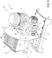
- FIG. 5 is a rear perspective view from above of the ma-chine of FIG. 4 , with a hood part remove for clearer illustration;
- FIG. 6 is a front perspective view of the machine of FIG. 1 , in which a dough forming tank and relative lid are illustrated in an exploded view with respect to a machine body;
- FIG. 7 is a rear perspective view of said dough forming tank
- FIG. 8 is a view similar to that of FIG. 7 , but wherein the operating tools, i.e. a kneading reel and a worm screw, are illustrated in said dough forming tank;
- the operating tools i.e. a kneading reel and a worm screw
- FIG. 9 is a vertical sectional view of the machine of FIG. 1 .
- the number 10 indicates, as a whole, an automatic table-top machine for kneading and extruding pasta according to an example of embodiment of the present invention.
- Said automatic table-top machine 10 for kneading and extruding pasta comprises, according to the prior art, a machine body 11 , which includes electric gear motor means 12 having an output shaft 12 . 1 with horizontal axis, transmission means 13 from said output shaft 12 . 1 to a driven shaft 14 with axis horizontal and parallel to the axis of said output shaft 12 . 1 and coaxial to a shaft 15 of a kneading reel 15 . 1 , projecting externally to said machine body 11 in a dough forming tank 16 , having below and parallel to said shaft 15 of the kneading reel 15 . 1 an extrusion channel 17 , in which there is arranged a worm screw 18 coaxial with respect to said output shaft 12 . 1 , which feeds in the manner of an auger extrusion means 19 for forming pasta ( FIG. 9 ).
- said reel 15 . 1 comprises a plurality of radial fingers fixed with respect to said shaft 15 and angularly staggered from one another.
- said machine body 11 advantageously comprises:
- the machine body 11 is enclosed between said load-bearing frame 20 and an encircling and removable hood 20 . 1 , having a removable vertical rear wall 20 . 2 , opposite said vertical wall 23 .
- said vertical plate 25 . 1 is connected with respect to said vertical wall 23 through spacer means.
- said transmission means 13 include first pinion means 13 . 1 mounted coaxial on said output shaft 12 . 1 and second pinion means 13 . 2 mounted coaxial on said driven shaft 14 , wherein said first 13 . 1 and second 13 . 2 pinion means are arranged in proximity of the face of said first plate 24 . 1 proximal to said vertical wall 23 , and flexible transmission means 13 . 3 , which engage said first 13 . 1 and second 13 . 2 pinion means ( FIG. 9 ).
- said flexible transmission means 13 . 3 consist of a transmission belt, or alternatively they can be produced in the manner of a transmission chain.
- pulley means can be provided (variant not illustrated).
- the end of said driven shaft 14 supported by said fourth bearing means 27 . 2 is facing the outside of said vertical wall 23 of said load-bearing frame 20 through a corresponding through hole, and has said detachable connection means 15 . 2 with axial coupling for a corresponding end of said shaft 15 of the kneading reel, which is rotated integral with the driven shaft 14 ( FIGS. 6 and 9 ).
- the end of said output shaft 12 . 1 supported by said third bearing means 27 . 1 is facing the outside of said vertical wall 23 of said load-bearing frame 20 through a corresponding through hole, and has said detachable connection means 18 . 1 with axial coupling for a corresponding end of said worm screw 18 , which is rotated integral with the output shaft 12 . 2 ( FIGS. 6 and 9 ).
- said inner reinforcement A comprises a substantially bell-shaped support 28 , axially perforated, having a peripheral outer flange 28 . 1 at the larger base thereof, and fixed by means of said flange 28 . 1 to the face of said first plate 24 . 1 distal from said vertical wall 23 , said substantially bell-shaped support 28 being axially passed through by said output shaft 12 . 1 and supporting said gear motor means 12 in a cantilever fashion ( FIGS. 4 and 9 ).
- said dough forming tank 16 is fixed with respect to said machine body 11 through detachable connection means 29 and is supported in a cantilever fashion with respect to said vertical wall 23 of said load-bearing frame 20 ( FIGS. 1, 2, 4, 6 and 9 ).
- said worm screw 18 is connected, at one end thereof, through detachable connection means 18 . 1 with respect to said output shaft 12 . 1 and, at the other end, is supported coaxially with respect to said extrusion means 19 .
- said shaft 15 of the reel 15 . 1 is connected through said detachable connection means 15 . 2 with respect to said driven shaft 14 .
- said tank 16 is structured in the manner of a hopper 16 . 1 , having two lateral chute-like walls 16 . 3 , opposite and converging at the bottom into said extrusion channel 17 , and two opposite walls, front 16 . 1 and rear 16 . 2 , substantially vertical.
- said rear wall 16 . 2 of said tank 16 is juxtaposed against the vertical wall 23 of said machine body 11 , and is structured as an essentially triangular stiffening frame 16 . 21 , comprising an upper horizontal cross-member 16 . 22 , which forms a top edge of said tank 16 , and a pair of essentially “V-shaped” branches 16 . 23 that form respective edges of said opposite lateral walls 16 . 3 and of said channel 17 of said tank 16 .
- peripheral frame 16 . 21 is extended beyond said tank 16 and provides an outer flange 16 . 24 fixed with respect to said tank 16 ( FIGS. 1 and 2 ).
- Said tank 16 is fixed with respect to said machine body 11 through said detachable connection means 29 and is supported in a cantilever fashion with respect to said vertical wall 23 of said load-bearing frame 20 ( FIGS. 1, 2, 4 and 9 ).
- said detachable connection means 29 connect said outer flange 16 . 24 with respect to said vertical wall 23 of said load-bearing frame 20 .
- said detachable connection means 29 comprise a plurality of manually controlled cam means 29 . 1 , arranged on the outer face of said vertical wall 23 of said load-bearing frame 20 , each of which comprises a cam 29 . 3 rotating about a respective pin 29 . 2 with axis horizontal and parallel to the axes of said shafts 12 . 1 , 14 , 15 , fixed to said vertical wall 23 in proximity of said outer flange 16 . 24 , wherein said rotating cam 29 . 3 has a front cam ramp 29 . 4 , which engages, in one direction of rotation, said outer flange 16 . 24 of said tank 16 , fixing the flange with pressure against said vertical wall 23 of said machine body 11 , and, in the opposite direction of rotation, disengages said outer flange 16 . 24 of said tank 16 , allowing removal of said tank 16 .
- Said cam means 29 comprise a radial wing integral with the cam body 29 . 3 , for the manual rotation of these same means.
- said extrusion means 19 are structured as a removable extrusion nozzle 19 . 1 , fixed to the outer face of said front wall 16 . 1 of said tank 16 and in which one end of said worm screw 18 is supported coaxially.
- said automatic machine 10 comprises a supporting and centering bushing 15 . 3 fixed to the outer face of said front wall 16 . 1 of said tank 16 , at a respective through hole and axially aligned with respect to said driven shaft 14 , one end of said shaft 18 of the reel 18 . 1 passing through said respective hole of said front wall 16 . 1 being supported coaxially and in a rotating and removable manner in said bushing 15 . 3 .
- said automatic machine 10 comprises, according the present example of embodiment of the invention:
- said automatic machine according to the invention comprises a gasket (not shown) interposed between said rear wall of said tank with corresponding outer flange of the same tank and said vertical wall of said machine body.
- said automatic table-top machine 10 for kneading and extruding pasta allows the stresses inside the machine body to be greatly limited, thereby avoiding the above problem.
- said machine 10 as stated, has an essentially simple structure, is easy to install and to carry out subsequent maintenance on, and has relatively low costs.
- the present invention allows the objects specified in the introduction to be achieved in a simple and advantageous manner.
Landscapes
- Life Sciences & Earth Sciences (AREA)
- Engineering & Computer Science (AREA)
- Food Science & Technology (AREA)
- Manufacturing And Processing Devices For Dough (AREA)
- Noodles (AREA)
- Formation And Processing Of Food Products (AREA)
Abstract
Description
-
- a load-bearing frame, including a sheet metal plate bent substantially to 90° and which provides, in a single body, a horizontal base, fixed with respect to supporting means on said table, and a vertical wall, on the outer face of which said dough forming tank is fixed, and
- an inner reinforcement comprising:
- first plate support means, including a first vertical plate, which is fixed with respect to said horizontal base, parallel to and spaced from said vertical wall,
- second plate support means, including a second vertical plate, which is fixed to the inner face of said vertical wall, and
- bearing means for supporting and sustaining said output shaft and said driven shaft, supported with respect to said first plate and to said second plate.
-
- a load-bearing
frame 20, including a sheet metal plate bent substantially to 90° and which provides, in a single body, ahorizontal base 21, fixed with respect to supportingmeans 22 on said table, and avertical wall 23, on the outer face of which saiddough forming tank 16 is fixed (FIGS. 5 and 9 ), and - an inner reinforcement A comprising:
- first plate support means 24, including a first vertical plate 24.1, which is fixed with respect to said
horizontal base 21, parallel to and spaced from saidvertical wall 23, - second plate support means 25, including a second vertical plate 25.1, which is fixed to the inner face of said
vertical wall 23, and - bearing means 26, 27 for supporting and sustaining said output shaft 12.1 and said driven shaft 14, supported with respect to said
first plate 24 and to said second plate 25 (FIGS. 5 and 9 ).
- a load-bearing
-
- said first plate support means 24 include said first vertical plate 24.1, which is fixed with respect to said
horizontal base 21, parallel to and spaced from saidvertical wall 23, and supports, in respective through holes with horizontal and parallel axes, first bearing means 26.1, through which the output shaft 12.1 of said gear motor means 12 passes, and second bearing means 26.2 over said first bearing means 26.1, - said second plate support means 25 include said second vertical plate 25.1, which is fixed to the inner face of said
vertical wall 23 and supports, at respective through holes with horizontal and parallel axes, third bearing means 27.1, in which the end of said output shaft 12.1 distal from saidgear motor means 12 is supported, and fourth bearing means 27.2 over said third bearing means 27.1 (FIG. 9 ). Said driven shaft 14 is sup-ported rotating freely between said third bearing means 26.2 and fourth bearing means 27.2.
- said first plate support means 24 include said first vertical plate 24.1, which is fixed with respect to said
-
- a
lid 30 that closes, in a removable manner, a top opening of saidtank 16 with hopper 16.1 and which has a lid part 30.1; - a lever arm 30.2 pivoting about a respective pin 30.3 with horizontal axis, fixed with respect to said
machine body 11, said arm 30.2 which can be pivoted in operation to a first pivoted position, in which a first part thereof rests by gravity in contact with said lid part 30.1 (FIGS. 1, 2, 4 and 9 ), and to other pivoted positions (FIG. 6 ), in which said first part thereof does not rest by gravity in contact with said lid part 30.1, and - microswitch means M, electrically connected with respect to an electric circuit to supply and control said gear motor means 12 and a member of which moving between an electrically closed position and an electrically open position is operatively associated with another part of said pivoting arm 30.2, so that the arrangement of said arm 30.2 in said first pivoted position causes the electrical closing of said electric circuit through said microswitch means M, while the arrangement of said arm 30.2 in said other pivoted positions causes the electrical opening of said electric circuit through said microswitch means M.
- a
Claims (4)
Applications Claiming Priority (2)
| Application Number | Priority Date | Filing Date | Title |
|---|---|---|---|
| IT102015000064089 | 2015-10-21 | ||
| ITUB2015A005307A ITUB20155307A1 (en) | 2015-10-21 | 2015-10-21 | AUTOMATIC BENCH MACHINE TO MIX AND EXTRUDE FOOD PASTA |
Publications (2)
| Publication Number | Publication Date |
|---|---|
| US20170112146A1 US20170112146A1 (en) | 2017-04-27 |
| US10869485B2 true US10869485B2 (en) | 2020-12-22 |
Family
ID=55315656
Family Applications (1)
| Application Number | Title | Priority Date | Filing Date |
|---|---|---|---|
| US15/298,622 Active 2038-11-30 US10869485B2 (en) | 2015-10-21 | 2016-10-20 | Automatic table-top machine for kneading and extruding pasta |
Country Status (7)
| Country | Link |
|---|---|
| US (1) | US10869485B2 (en) |
| EP (1) | EP3158870B1 (en) |
| CN (1) | CN106689255B (en) |
| CA (1) | CA2946068A1 (en) |
| ES (1) | ES2686771T3 (en) |
| IT (1) | ITUB20155307A1 (en) |
| PL (1) | PL3158870T3 (en) |
Families Citing this family (1)
| Publication number | Priority date | Publication date | Assignee | Title |
|---|---|---|---|---|
| CA171010S (en) * | 2016-07-26 | 2017-05-23 | Imperia & Monferrina S P A | Pasta maker |
Citations (6)
| Publication number | Priority date | Publication date | Assignee | Title |
|---|---|---|---|---|
| US4269582A (en) | 1978-11-21 | 1981-05-26 | Mario Mella | Pasta-making machine |
| US4332539A (en) * | 1979-06-07 | 1982-06-01 | R. Bialetti & C. S.P.A. | Pasta machine |
| US4391575A (en) * | 1980-09-05 | 1983-07-05 | Osrow Products Corp. | Kitchen appliance for making farinaceous products |
| US4883361A (en) * | 1988-06-09 | 1989-11-28 | B-V Dough Handling Systems, Inc. | Dough processing apparatus |
| US5460506A (en) | 1995-01-09 | 1995-10-24 | Mitco International, Ltd. | Home pasta maker |
| KR20100008840U (en) | 2009-02-27 | 2010-09-06 | 하복진 | Gear box for noodle making device |
Family Cites Families (4)
| Publication number | Priority date | Publication date | Assignee | Title |
|---|---|---|---|---|
| CN2200297Y (en) * | 1994-04-19 | 1995-06-14 | 徐名勇 | Small-sized noodles make-up machine |
| KR20080000053U (en) * | 2007-12-20 | 2008-01-10 | 하복진 | Kneading machine |
| KR101140915B1 (en) * | 2009-04-24 | 2012-05-03 | 박준호 | sujebi machine |
| KR20130003951U (en) * | 2011-12-22 | 2013-07-02 | 하복진 | Kneading machine |
-
2015
- 2015-10-21 IT ITUB2015A005307A patent/ITUB20155307A1/en unknown
-
2016
- 2016-10-19 ES ES16002248.9T patent/ES2686771T3/en active Active
- 2016-10-19 PL PL16002248T patent/PL3158870T3/en unknown
- 2016-10-19 EP EP16002248.9A patent/EP3158870B1/en active Active
- 2016-10-20 CA CA2946068A patent/CA2946068A1/en active Pending
- 2016-10-20 US US15/298,622 patent/US10869485B2/en active Active
- 2016-10-21 CN CN201611271014.2A patent/CN106689255B/en active Active
Patent Citations (6)
| Publication number | Priority date | Publication date | Assignee | Title |
|---|---|---|---|---|
| US4269582A (en) | 1978-11-21 | 1981-05-26 | Mario Mella | Pasta-making machine |
| US4332539A (en) * | 1979-06-07 | 1982-06-01 | R. Bialetti & C. S.P.A. | Pasta machine |
| US4391575A (en) * | 1980-09-05 | 1983-07-05 | Osrow Products Corp. | Kitchen appliance for making farinaceous products |
| US4883361A (en) * | 1988-06-09 | 1989-11-28 | B-V Dough Handling Systems, Inc. | Dough processing apparatus |
| US5460506A (en) | 1995-01-09 | 1995-10-24 | Mitco International, Ltd. | Home pasta maker |
| KR20100008840U (en) | 2009-02-27 | 2010-09-06 | 하복진 | Gear box for noodle making device |
Also Published As
| Publication number | Publication date |
|---|---|
| CN106689255B (en) | 2021-08-10 |
| EP3158870B1 (en) | 2018-06-13 |
| EP3158870A1 (en) | 2017-04-26 |
| PL3158870T3 (en) | 2018-11-30 |
| US20170112146A1 (en) | 2017-04-27 |
| CA2946068A1 (en) | 2017-04-21 |
| ES2686771T3 (en) | 2018-10-19 |
| CN106689255A (en) | 2017-05-24 |
| ITUB20155307A1 (en) | 2017-04-21 |
Similar Documents
| Publication | Publication Date | Title |
|---|---|---|
| US20170112147A1 (en) | Automatic table-top machine for kneading and extruding pasta | |
| ITMI20100707A1 (en) | MACHINE FOR THE TREATMENT OF FOOD MIXTURES WITH CENTRALIZED ACTIVATION | |
| AU2016380513A1 (en) | Large-capacity juicer | |
| US10869485B2 (en) | Automatic table-top machine for kneading and extruding pasta | |
| CN105836391B (en) | Light-duty short distance Belt Conveying equipment | |
| KR102387801B1 (en) | Leek cutting device | |
| KR20140146019A (en) | Automatic assembly apparatus for needle roller | |
| CN221769307U (en) | A drying device for tobacco shreds | |
| HK1237595B (en) | Automatic table-top machine for kneading and extruding pasta | |
| CN209861663U (en) | Grain threshing mechanism | |
| CN108906189A (en) | A kind of instrument production scrap glass cover crushing device | |
| HK1237595A1 (en) | Automatic table-top machine for kneading and extruding pasta | |
| HK1237595A (en) | Automatic table-top machine for kneading and extruding pasta | |
| EP1969943A1 (en) | Kneading machine for food products | |
| HK1238087B (en) | Automatic table-top machine for kneading and extruding pasta | |
| HK1238087A (en) | Automatic table-top machine for kneading and extruding pasta | |
| HK1238087A1 (en) | Automatic table-top machine for kneading and extruding pasta | |
| KR101914279B1 (en) | Simple meat cutting device for keeping balance of chopper, and apparatus for slice cutting meat having the same | |
| KR20160004512U (en) | Rotary shaft support device | |
| KR102438045B1 (en) | Apparatus for making kimchi | |
| CN108940007B (en) | Mix integration flowing water equipment of material ejection of compact fast | |
| US8496463B2 (en) | Extruder feed section with pivotable feed roll assembly | |
| US1463114A (en) | bostrom | |
| KR101836178B1 (en) | Apparatus for cutting rice cake | |
| KR200442522Y1 (en) | Fish cake molding machine |
Legal Events
| Date | Code | Title | Description |
|---|---|---|---|
| AS | Assignment |
Owner name: IMPERIA & MONFERRINA S.P.A., ITALY Free format text: ASSIGNMENT OF ASSIGNORS INTEREST;ASSIGNOR:PORCARI, GABRIELE;REEL/FRAME:040590/0915 Effective date: 20161015 |
|
| STPP | Information on status: patent application and granting procedure in general |
Free format text: DOCKETED NEW CASE - READY FOR EXAMINATION |
|
| STPP | Information on status: patent application and granting procedure in general |
Free format text: NON FINAL ACTION MAILED |
|
| STPP | Information on status: patent application and granting procedure in general |
Free format text: RESPONSE TO NON-FINAL OFFICE ACTION ENTERED AND FORWARDED TO EXAMINER |
|
| STPP | Information on status: patent application and granting procedure in general |
Free format text: NON FINAL ACTION MAILED |
|
| STPP | Information on status: patent application and granting procedure in general |
Free format text: PUBLICATIONS -- ISSUE FEE PAYMENT VERIFIED |
|
| STCF | Information on status: patent grant |
Free format text: PATENTED CASE |
|
| MAFP | Maintenance fee payment |
Free format text: PAYMENT OF MAINTENANCE FEE, 4TH YR, SMALL ENTITY (ORIGINAL EVENT CODE: M2551); ENTITY STATUS OF PATENT OWNER: SMALL ENTITY Year of fee payment: 4 |