US10868363B2 - Antenna system and signal transmission method - Google Patents
Antenna system and signal transmission method Download PDFInfo
- Publication number
- US10868363B2 US10868363B2 US15/996,525 US201815996525A US10868363B2 US 10868363 B2 US10868363 B2 US 10868363B2 US 201815996525 A US201815996525 A US 201815996525A US 10868363 B2 US10868363 B2 US 10868363B2
- Authority
- US
- United States
- Prior art keywords
- matching network
- transmit end
- matrix
- antenna array
- end matching
- Prior art date
- Legal status (The legal status is an assumption and is not a legal conclusion. Google has not performed a legal analysis and makes no representation as to the accuracy of the status listed.)
- Active, expires
Links
Images


Classifications
-
- H—ELECTRICITY
- H01—ELECTRIC ELEMENTS
- H01Q—ANTENNAS, i.e. RADIO AERIALS
- H01Q1/00—Details of, or arrangements associated with, antennas
- H01Q1/52—Means for reducing coupling between antennas; Means for reducing coupling between an antenna and another structure
- H01Q1/521—Means for reducing coupling between antennas; Means for reducing coupling between an antenna and another structure reducing the coupling between adjacent antennas
- H01Q1/523—Means for reducing coupling between antennas; Means for reducing coupling between an antenna and another structure reducing the coupling between adjacent antennas between antennas of an array
-
- H—ELECTRICITY
- H04—ELECTRIC COMMUNICATION TECHNIQUE
- H04B—TRANSMISSION
- H04B1/00—Details of transmission systems, not covered by a single one of groups H04B3/00 - H04B13/00; Details of transmission systems not characterised by the medium used for transmission
- H04B1/38—Transceivers, i.e. devices in which transmitter and receiver form a structural unit and in which at least one part is used for functions of transmitting and receiving
- H04B1/40—Circuits
-
- H—ELECTRICITY
- H04—ELECTRIC COMMUNICATION TECHNIQUE
- H04B—TRANSMISSION
- H04B7/00—Radio transmission systems, i.e. using radiation field
- H04B7/02—Diversity systems; Multi-antenna system, i.e. transmission or reception using multiple antennas
- H04B7/04—Diversity systems; Multi-antenna system, i.e. transmission or reception using multiple antennas using two or more spaced independent antennas
- H04B7/0413—MIMO systems
-
- G—PHYSICS
- G01—MEASURING; TESTING
- G01S—RADIO DIRECTION-FINDING; RADIO NAVIGATION; DETERMINING DISTANCE OR VELOCITY BY USE OF RADIO WAVES; LOCATING OR PRESENCE-DETECTING BY USE OF THE REFLECTION OR RERADIATION OF RADIO WAVES; ANALOGOUS ARRANGEMENTS USING OTHER WAVES
- G01S7/00—Details of systems according to groups G01S13/00, G01S15/00, G01S17/00
- G01S7/02—Details of systems according to groups G01S13/00, G01S15/00, G01S17/00 of systems according to group G01S13/00
- G01S7/28—Details of pulse systems
-
- H—ELECTRICITY
- H01—ELECTRIC ELEMENTS
- H01Q—ANTENNAS, i.e. RADIO AERIALS
- H01Q21/00—Antenna arrays or systems
-
- H—ELECTRICITY
- H01—ELECTRIC ELEMENTS
- H01Q—ANTENNAS, i.e. RADIO AERIALS
- H01Q21/00—Antenna arrays or systems
- H01Q21/06—Arrays of individually energised antenna units similarly polarised and spaced apart
- H01Q21/061—Two dimensional planar arrays
-
- H—ELECTRICITY
- H04—ELECTRIC COMMUNICATION TECHNIQUE
- H04B—TRANSMISSION
- H04B1/00—Details of transmission systems, not covered by a single one of groups H04B3/00 - H04B13/00; Details of transmission systems not characterised by the medium used for transmission
- H04B1/62—Details of transmission systems, not covered by a single one of groups H04B3/00 - H04B13/00; Details of transmission systems not characterised by the medium used for transmission for providing a predistortion of the signal in the transmitter and corresponding correction in the receiver, e.g. for improving the signal/noise ratio
Definitions
- the present invention relates to the field of wireless mobile communications, and in particular, to an antenna system and a signal transmission method.
- a multiple-input multiple-output (MIMO) antenna system can greatly improve transmission quality and transmission efficiency of a radio communications link. Therefore, the MIMO antenna system has become one of key technologies for commercially using wireless mobile communications both in and outside China.
- a massive MIMO antenna system having characteristics such as a large capacity, high reliability and green low power consumption emerges, and quickly attracts much attention of academia and vendors of network and communications devices.
- an antenna is usually limited in actual design in terms of a size. Because a massive MIMO antenna usually includes hundreds of or even more antenna array elements, a spacing between massive MIMO antenna array elements needs to be reduced when there is a size limit.
- a decrease in a spacing between antenna array elements increases an array element coupling effect between the antenna array elements.
- the array element coupling effect means that electromagnetic field interaction between adjacent array elements of an antenna array changes an induced current or an induced voltage of each array element, thereby distorting an originally uncoupled receive or transmit signal on the antenna array element.
- an increase in the coupling effect between the antenna array elements has relatively great impact on a spatial correlation of antenna signals, an antenna gain, and even a system capacity.
- Embodiments of the present invention provide an antenna system and a signal transmission method, so as to reduce a coupling effect between antenna array elements.
- an embodiment of the present invention provides an antenna system.
- the antenna system includes: a transmit end antenna array and a transmit end matching network, where an S parameter matrix of the transmit end matching network matches an S parameter matrix of the transmit end antenna array and is configured to perform pre-distortion on a to-be-transmitted signal, and the transmit end antenna array is configured to transmit the to-be-transmitted signal that has been pre-distorted by the transmit end matching network.
- the matching network matches the antenna array.
- pre-distortion may be performed on a signal that needs to be transmitted by the antenna array or de-distortion may be performed on a signal received by the antenna array, so as to configure energy that is coupled from each antenna array element to an adjacent antenna array element, thereby reducing a coupling effect between antenna array elements.
- the transmit end matching network is a multiport conjugate matching network or a self-impedance matching network of the transmit end antenna array.
- the transmit end matching network may greatly reduce a coupling effect between antenna array elements, thereby greatly lowering a requirement for a spacing between the antenna array elements and greatly reducing a size of the antenna system.
- the S parameter matrix of the transmit end matching network is
- S _ _ M T X ( S _ _ 11 T X S _ _ 12 T X S _ _ 21 T X S _ _ 22 T X ) , where S 11 T X is a self-reflection coefficient matrix of an input port of the transmit end matching network, S 22 T X is a self-reflection coefficient matrix of an output port of the transmit end matching network, S 12 T X is a backward transmission matrix that is transmitted backward from the output port to the input port of the transmit end matching network, and S 21 T X is a forward transmission matrix that is transmitted forward from the input port to the output port of the transmit end matching network.
- the transmit end matching network is determined by using the S parameter matrix, so that a characteristic of the transmit end matching network can be easily determined.
- S TT is the S parameter matrix of the transmit end antenna array
- S TT is the S parameter matrix of the transmit end antenna array
- diag( ⁇ ) is an operation of taking diagonal elements of a matrix to form a diagonal matrix
- an array element spacing of the transmit end antenna array is less than a half of a first wavelength, where the array element spacing is an inter-row spacing or an inter-column spacing between antenna array elements included in the transmit end antenna array, and the first wavelength is a wavelength of a signal carrier transmitted by the antenna system.
- the array element spacing is less than the first wavelength, thereby greatly reducing a size of the antenna array, and reducing a size of the antenna system.
- an embodiment of the present invention further provides another antenna system, including: a receive end antenna array and a receive end matching network, where the receive end antenna array is configured to convert an incident electromagnetic signal radiated by a spatial physical channel into a voltage signal or a current signal; and an S parameter matrix of the receive end matching network matches an S parameter matrix of the receive end antenna array and is configured to perform de-distortion on the voltage signal or the current signal.
- the receive end matching network is a multiport conjugate matching network or a self-impedance matching network of the receive end antenna array.
- the S parameter matrix of the receive end matching network is
- S _ _ M R X ( S _ _ 11 R X S _ _ 12 R X S _ _ 21 R X S _ _ 22 R X ) , where S 11 R X is a self-reflection coefficient matrix of an input port of the receive end matching network, S 22 R X is a self-reflection coefficient matrix of an output port of the receive end matching network, S 12 R X is a backward transmission matrix that is transmitted backward from the output port to the input port of the receive end matching network, and S 21 R X is a forward transmission matrix that is transmitted forward from the input port to the output port of the receive end matching network.
- S RR the S parameter matrix of the receive end antenna array
- ⁇ any unit diagonal complex matrix
- S RR is the S parameter matrix of the receive end antenna array
- diag( ⁇ ) is an operation of taking diagonal elements of a matrix to form a diagonal matrix
- an array element spacing of the receive end antenna array is less than a half of a second wavelength, where the array element spacing is an inter-row spacing or an inter-column spacing between antenna array elements included in the receive end antenna array, and the second wavelength is a wavelength of a signal carrier received by the antenna system.
- an embodiment of the present invention further provides a signal transmission method.
- the method includes: generating a to-be-transmitted signal; performing pre-distortion on the to-be-transmitted signal according to an S parameter matrix of a transmit end matching network, where the S parameter matrix matches an S parameter matrix of a transmit end antenna array; and transmitting, by using the transmit end matching network, the to-be-transmitted signal that has been pre-distorted.
- an embodiment of the present invention further provides another signal transmission method.
- the method includes: converting an incident electromagnetic signal radiated by a spatial physical channel into a voltage signal or a current signal by using a receive end antenna array; performing de-distortion on the voltage signal or the current signal according to an S parameter matrix of a receive end matching network, where the S parameter matrix of the receive end matching network matches an S parameter matrix of the receive end antenna array; and transmitting the voltage signal or the current signal that has been de-distorted to a load.
- FIG. 1 is a schematic structural diagram of an embodiment of an antenna system according to the present invention.
- FIG. 2 is a schematic architectural diagram of an embodiment of a transmit end according to the present invention.
- FIG. 3 is a schematic architectural diagram of an embodiment of a receive end according to the present invention.
- FIG. 4 is a schematic flowchart of an embodiment of a signal transmission method according to the present invention.
- FIG. 5 is a schematic flowchart of another embodiment of a signal transmission method according to the present invention.
- FIG. 1 is a schematic structural diagram of an antenna system according to the present invention.
- the antenna system in this embodiment of the present invention may include multiple parts such as an antenna array 101 and a matching network 102 that matches the antenna array 101 .
- the antenna array 101 includes a transmit antenna and a receive antenna that are used by a base station and a terminal.
- the antenna array 101 may be a massive MIMO antenna array, and the matching network 102 may be a circuit network.
- the antenna array 101 is a transmit end antenna array, and the matching network 102 is configured to perform pre-distortion on a signal that needs to be transmitted by the antenna array 101 .
- the antenna system is a receive antenna system, the antenna array is a receive end antenna array, and the matching network 102 is configured to perform de-distortion on a signal received by the antenna array 101 .
- the matching network 102 may configure, by means of pre-distortion or de-distortion, energy that is coupled from each antenna array element to an adjacent antenna array element, so as to suppress signal distortion generated when the antenna array transmits a signal, or suppress signal distortion of a signal received by the antenna array, thereby reducing a coupling effect between antenna array elements.
- Matching between the matching network 102 and the antenna array 101 means that a scattering parameter (S parameter) matrix of the matching network 102 matches an S parameter matrix of the antenna array 101 .
- Matching between the S parameter matrix of the matching network 102 and the S parameter matrix of the antenna array 101 means that the S parameter matrix of the matching network 102 is set based on the S parameter matrix of the antenna array 101 , so that the matching network 102 cancels or partially cancels signal distortion generated when the antenna array 101 transmits a signal, or cancels or partially cancels signal distortion of a signal received by the antenna array 101 .
- Matching between the matching network 102 and the antenna array 101 include multiport conjugate matching, self-impedance matching, and the like.
- the S parameter matrix of the matching network 102 may be represented as
- S _ _ M ( S _ _ 11 S _ _ 12 S _ _ 21 S _ _ 22 ) , where S 11 is a self-reflection coefficient matrix of an input port of the matching network 102 , S 22 is a self-reflection coefficient matrix of an output port of the matching network 102 , S 12 is a backward transmission matrix that is transmitted backward from the output port of the matching network 102 to the input port of the matching network 102 , and S 21 is a forward transmission matrix that is transmitted forward from the input port of the matching network 102 to the output port of the matching network 102 .
- the input port is a port for connecting the matching network and a transmit end excitation source, that is, a port 1 shown in FIG. 2
- the output port is a port for connecting the matching network and the antenna array, that is, a port 2 shown in FIG. 2 .
- the input port is a port for connecting the matching network and the receive end antenna array, that is, a port 1 shown in FIG. 3
- the output port is a port for connecting the matching network and a load, that is, a port 2 shown in FIG. 3 .
- S Ant is an S parameter matrix of the transmit end antenna array or the receive end antenna array
- FIG. 2 is a schematic architectural diagram of a transmit end of the present invention.
- the transmit end may include an excitation source 201 and a transmit antenna system 202
- the transmit antenna system 202 may include a transmit end antenna array 2021 and a transmit end matching network 2022
- a port for connecting the transmit end matching network 2022 and the excitation source 201 is an input port of the transmit end matching network 2022 , that is, a port 1 shown in FIG. 2
- a port for connecting the transmit end matching network 2022 and the transmit end antenna array 2021 is an output port of the transmit end matching network 2022 , that is, a port 2 shown in FIG. 2 .
- the excitation source 201 is configured to provide a to-be-transmitted signal.
- the transmit end matching network 2022 is configured to perform pre-distortion on the to-be-transmitted signal according to an S parameter matrix of the transmit end matching network 2022 , so as to configure energy that is coupled from each antenna array element to an adjacent antenna array element, thereby canceling or partially canceling signal distortion generated when the transmit end antenna array 2021 transmits a signal, and suppressing a coupling effect between antenna array elements.
- the transmit end antenna array 2021 is configured to transmit the to-be-transmitted signal that has been pre-distorted by the transmit end matching network 2022 .
- the transmit end antenna array 2021 may be a massive MIMO antenna array of a base station or a mobile terminal antenna array provided with a plurality of transmit antennas.
- the transmit end antenna array 2021 may include a plurality of antenna array elements, and the antenna array elements may use cross-polarization array element deployment, or may use co-polarization array element deployment.
- an array element spacing of the transmit end antenna array is less than a half of a first wavelength.
- the first wavelength is a wavelength of a signal carrier transmitted by the antenna system, and the array element spacing is an inter-row spacing or an inter-column spacing between antenna array elements included in the transmit end antenna array.
- the inter-column spacing between the antenna array elements is represented as d H
- the inter-row spacing between the antenna array elements is represented as d V
- the wavelength of the signal carrier transmitted by the antenna system is represented as ⁇ 1
- at least one of d H or d V may be less than a half of ⁇ 1 .
- an S parameter matrix of the excitation source 201 may be represented as S S
- an S parameter matrix of the transmit end matching network 2022 may be represented as S M T X
- an S parameter matrix of the transmit end antenna array 2021 may be represented as S TT .
- S M T X may match S TT , so that the transmit end matching network 2022 can perform pre-distortion on a to-be-transmitted signal generated by the excitation source 201 , and feed a signal generated after the pre-distortion to the transmit end antenna array 2021 .
- energy that is coupled from each antenna array element to an adjacent antenna array element can be configured, so as to reduce a coupling effect between antenna array elements.
- the transmit end matching network 2022 can control signal input and output, the transmit end matching network 2022 may be represented by an S parameter matrix
- S _ _ M T X ( S _ _ 11 T X S _ _ 12 T X S _ _ 21 T X S _ _ 22 T X ) , where S 11 T X is a self-reflection coefficient matrix of an input port of the transmit end matching network 2022 , S 22 T X is a self-reflection coefficient matrix of an output port of the transmit end matching network 2022 , S 12 T X is a backward transmission matrix that is transmitted backward from the output port to the input port of the transmit end matching network 2022 , and S 21 T X is a forward transmission matrix that is transmitted forward from the input port to the output port of the transmit end matching network 2022 .
- a specific manner of matching S M T X and S TT varies with different requirements for signal transmission performance and different requirements for complexity of the transmit end matching network 2022 .
- the transmit end matching network 2022 may be a multiport conjugate matching network or a self-impedance matching network of the transmit end antenna array 2021 .
- submatrixes such as S 11 T X , S 22 T X , S 12 T X , and S 21 T X are also different from each other.
- S TT is the S parameter matrix of the transmit end antenna array 2021
- S TT is the S parameter matrix of the transmit end antenna array 2021
- a circuit structure conforming to a parameter value of each port may be designed according to a specific circuit design criterion, so as to obtain a circuit network that is used as the transmit end matching network 2022 .
- a specific circuit structure design method of the transmit end matching network 2022 and a specific circuit structure of the transmit end matching network 2022 are not described herein.
- radiant power performance can be improved when a transmit end matching network is accessed between an excitation source and a transmit end antenna array.
- a multiport conjugate matching network can keep highest actual radiant power, that is, the actual radiant power is consistent with original output power.
- self-impedance matching can also improve radiant power performance to an extent. For example, when the antenna array element spacing is from 0.3 to 0.5 ⁇ , the actual radiant power can still be 90% of the original output power.
- a correlation of transmit signals can further be reduced, and a system capacity can further be improved.
- FIG. 3 is a schematic architectural diagram of a receive end according to the present invention.
- the receive end may include a receive antenna system 301 and a load 302
- the receive antenna system 301 may include a receive end antenna array 3011 and a receive end matching network 3012
- a port for connecting the receive end matching network 3012 and the receive end antenna array 3011 is an input port of the receive end matching network 3012 , that is, a port 1 shown in FIG. 3
- a port for connecting the receive end matching network 3012 and the load 302 is an output port of the receive end matching network 3012 , that is, a port 2 shown in FIG. 3 .
- the receive end antenna array 3011 is configured to convert an incident electromagnetic signal radiated by a spatial physical channel into a voltage signal or a current signal.
- the receive end matching network 3012 is configured to perform de-distortion on the voltage signal or the current signal according to an S parameter matrix of the receive end antenna array 3011 , so as to configure energy that is coupled from an antenna array element to an adjacent antenna array element, thereby suppressing distortion of the voltage signal or the current signal, and reducing a coupling effect between antenna array elements.
- the load 302 is configured to receive the voltage signal or the current signal that has been de-distorted by the receive end matching network 3012 .
- the receive end antenna array 3011 may be a massive MIMO antenna array of a base station or a mobile terminal antenna array provided with a plurality of receive antennas.
- the receive end antenna array 3011 may include a plurality of antenna array elements, and the antenna array elements may use cross-polarization array element deployment, or may use co-polarization array element deployment.
- an array element spacing of the receive end antenna array is less than a half of a second wavelength.
- the second wavelength is a wavelength of a signal carrier received by the antenna system, and the array element spacing is an inter-row spacing or an inter-column spacing between antenna array elements included in the receive end antenna array.
- the inter-column spacing between the antenna array elements is represented as d H
- the inter-row spacing between the antenna array elements is represented as d V
- the wavelength of the signal carrier received by the antenna system is represented as ⁇ 2
- at least one of d H or d V may be less than a half of ⁇ 2 .
- the load 302 is configured to obtain signal energy that has been received and processed, and the load 302 may be a specific communications device such as a radio frequency unit or a baseband processing unit.
- the receive end matching network 3012 may be a circuit network.
- the receive end may be described by using an S parameter matrix.
- the S parameter matrix of the receive end antenna array 3011 may be represented as S RR
- an S parameter matrix of the receive end matching network 3012 may be represented as S M R X
- an S parameter matrix of the load 302 may be represented as S L .
- S M R X may match S RR , so that the receive end matching network 3012 can perform de-distortion on a voltage signal or a current signal obtained after the receive end converts an electromagnetic signal.
- energy that is coupled from each antenna array element to an adjacent antenna array element is configured, so as to reduce a coupling effect between antenna array elements, and feed the signal that has been de-distorted to the load 302 .
- the receive end matching network 3012 can also control signal input and output, the receive end matching network 3012 may be represented by an S parameter matrix
- S _ _ M R X ( S _ _ 11 R X S _ _ 12 R X S _ _ 21 R X S _ _ 22 R X ) , where S 11 R X is a self-reflection coefficient matrix of the input port of the receive end matching network 3012 , S 22 R X is a self-reflection coefficient matrix of the output port of the receive end matching network 3012 , S 12 R X is a backward transmission matrix that is transmitted backward from the output port to the input port of the receive end matching network 3012 , and S 21 R X is a forward transmission matrix that is transmitted forward from the input port to the output port of the receive end matching network 3012 .
- the receive end matching network 3012 may be a multiport conjugate matching network or a self-impedance matching network of the receive end antenna array 3011 .
- S RR is the S parameter matrix of the receive end antenna array 3011
- ⁇ any unit diagonal complex matrix.
- S RR is the S parameter matrix of the receive end antenna array 3011
- a basic principle of the receive end matching network 3012 is consistent with that of the transmit end matching network. Therefore, for a manner of determining S 11 Rx , S 22 Rx , S 12 Rx , and S 21 Rx , refer to a manner of determining S 11 T X , S 22 T X , S 12 R X , and S 21 R X . Details are not described herein again.
- a circuit structure conforming to a parameter value of each port may be designed according to a specific circuit design criterion, so as to obtain a circuit network that is used as the receive end matching network 3012 .
- a specific circuit structure design method of the receive end matching network 3012 and a specific circuit structure of the receive end matching network 3012 are not described herein again.
- the receive end matching network can effectively reduce a correlation of receive signals, maximize receive power, and improve a system capacity.
- the receive end matching network is a self-impedance matching network and an antenna array element spacing is from 0.3 to 0.5 ⁇
- the receive signals can be basically de-correlated after the receive end matching network performs de-distortion on receive signals generated by the receive end antenna array.
- a signal transmission method is further provided in the present invention.
- FIG. 4 is a schematic flowchart of an embodiment of a signal transmission method according to the present invention.
- Step 401 Generate a to-be-transmitted signal.
- Step 402 Perform pre-distortion on the to-be-transmitted signal according to an S parameter matrix of a transmit end matching network, so as to configure energy that is coupled from each antenna array element to an adjacent antenna array element, thereby reducing a coupling effect between antenna array elements.
- Pre-distortion performed on the to-be-transmitted signal according to an S parameter matrix of a transmit end matching network may be completed by using a transmit end matching network circuit.
- An S parameter matrix of the transmit end matching network circuit matches an S parameter matrix of a transmit end antenna array.
- Step 403 Transmit, by using a transmit end antenna array, the to-be-transmitted signal that has been pre-distorted.
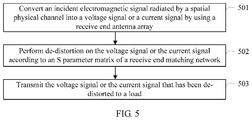
- FIG. 5 is a schematic flowchart of another embodiment of a signal transmission method according to the present invention.
- Step 501 Convert an incident electromagnetic signal radiated by a spatial physical channel into a voltage signal or a current signal by using a receive end antenna array.
- Step 502 Perform de-distortion on the voltage signal or the current signal according to an S parameter matrix of a receive end matching network, so as to configure energy that is coupled from each antenna array element to an adjacent antenna array element, thereby reducing a coupling effect between antenna array elements.
- De-distortion performed on the voltage signal or the current signal according to an S parameter matrix of a receive end matching network may be completed by using a receive end matching network circuit.
- An S parameter matrix of the receive end matching network circuit matches an S parameter matrix of the receive end antenna array.
- Step 503 Transmit the voltage signal or the current signal that has been de-distorted to a load.
- the present invention further provides a computer storage medium.
- the computer storage medium may store a program, and when the program is executed, some or all of the steps of each embodiment of the signal transmission method provided in the present invention may be included.
- the storage medium may be a magnetic disk, an optical disc, a read-only memory (ROM) or a random access memory (RAM), or the like.
- pre-distortion is performed on a signal transmitted by the antenna array or de-distortion is performed on a signal received by the antenna array, so that energy that is coupled from each antenna array element to an adjacent antenna array element can be configured, thereby reducing a coupling effect between antenna array elements.
- the matching network is introduced into the antenna system, so that an antenna architecture design does not need to always consider a performance indicator limitation imposed when the antenna array elements are tightly coupled.
- the matching network is introduced, so that a massive MIMO antenna size can be reduced, and the antenna array elements can be more flexibly arranged under a requirement for a specific antenna size.
- the technologies in the embodiments of the present invention may be implemented by software in addition to a necessary general hardware platform.
- the technical solutions of the present invention essentially or the part contributing to the prior art may be implemented in a form of a software product.
- the software product is stored in a storage medium, such as a ROM/RAM, a hard disk, or an optical disc, and includes several instructions for instructing a computer device (which may be a personal computer, a server, or a network device) to perform the methods described in the embodiments or some parts of the embodiments of the present invention.
Abstract
Description
where
where
where
where
where
Claims (10)
Applications Claiming Priority (1)
| Application Number | Priority Date | Filing Date | Title |
|---|---|---|---|
| PCT/CN2015/098428 WO2017107096A1 (en) | 2015-12-23 | 2015-12-23 | Antenna system and signal transmission method |
Related Parent Applications (1)
| Application Number | Title | Priority Date | Filing Date |
|---|---|---|---|
| PCT/CN2015/098428 Continuation WO2017107096A1 (en) | 2015-12-23 | 2015-12-23 | Antenna system and signal transmission method |
Publications (2)
| Publication Number | Publication Date |
|---|---|
| US20180277947A1 US20180277947A1 (en) | 2018-09-27 |
| US10868363B2 true US10868363B2 (en) | 2020-12-15 |
Family
ID=59088871
Family Applications (1)
| Application Number | Title | Priority Date | Filing Date |
|---|---|---|---|
| US15/996,525 Active 2036-01-07 US10868363B2 (en) | 2015-12-23 | 2018-06-04 | Antenna system and signal transmission method |
Country Status (6)
| Country | Link |
|---|---|
| US (1) | US10868363B2 (en) |
| EP (1) | EP3373029B1 (en) |
| JP (1) | JP6699849B2 (en) |
| KR (1) | KR102142396B1 (en) |
| CN (1) | CN107850662B (en) |
| WO (1) | WO2017107096A1 (en) |
Families Citing this family (2)
| Publication number | Priority date | Publication date | Assignee | Title |
|---|---|---|---|---|
| CN110596720A (en) * | 2019-08-19 | 2019-12-20 | 深圳奥锐达科技有限公司 | Distance measuring system |
| KR102555056B1 (en) * | 2021-10-27 | 2023-07-17 | 전북대학교산학협력단 | Closed-loop multi-antenna system and method for closed-loop multi-antenna communication security thereof |
Citations (14)
| Publication number | Priority date | Publication date | Assignee | Title |
|---|---|---|---|---|
| WO2007124766A1 (en) | 2006-04-28 | 2007-11-08 | Telefonaktiebolaget Lm Ericsson (Publ) | Method and device for coupling cancellation of closely spaced antennas |
| CN101452073A (en) | 2007-11-30 | 2009-06-10 | 清华大学 | Broadband signal synthesizing method based on multi-sending and multi-receiving frequency division radar |
| JP2010503261A (en) | 2006-09-05 | 2010-01-28 | ソニー エリクソン モバイル コミュニケーションズ, エービー | Antenna system and method for operating antenna system |
| US20110222444A1 (en) * | 2010-03-12 | 2011-09-15 | Rf Micro Devices, Inc. | Split-band power amplifiers and duplexers for lte-advanced front end for improved imd |
| US20110250926A1 (en) * | 2009-12-21 | 2011-10-13 | Qualcomm Incorporated | Dynamic antenna selection in a wireless device |
| US20120009983A1 (en) | 2010-07-06 | 2012-01-12 | Mow Matt A | Tunable antenna systems |
| CN102856646A (en) | 2012-09-14 | 2013-01-02 | 重庆大学 | Decoupling matching network for compact antenna array |
| US20130052964A1 (en) | 2011-08-26 | 2013-02-28 | Paul J. Husted | Adaptive interference cancellation for transmitter distortion calibration in multi-antenna transmitters |
| CN104280732A (en) | 2014-09-16 | 2015-01-14 | 电子科技大学 | Through-the-wall radar architectural composition imaging method based on equivalent collaborative arrays |
| US20150063486A1 (en) | 2013-03-21 | 2015-03-05 | Tekcem | Method and device for radio reception using a plurality of antennas and a multiple-input-port and multiple-output-port amplifier |
| CN104425890A (en) | 2013-09-09 | 2015-03-18 | 中国移动通信集团广东有限公司 | Decoupling circuit, terminal and setting method of decoupling circuit |
| WO2015069478A1 (en) | 2013-11-06 | 2015-05-14 | Ixia | Systems and methods for improved wireless channel estimation |
| CN104993881A (en) | 2015-06-19 | 2015-10-21 | 中国人民解放军信息工程大学 | Rapid analysis method of MIMO antenna mutual-coupling characteristic |
| WO2015172807A1 (en) | 2014-05-12 | 2015-11-19 | Nokia Solutions And Networks Gmbh & Co. Kg | A method, apparatus and system |
-
2015
- 2015-12-23 KR KR1020187018132A patent/KR102142396B1/en active IP Right Grant
- 2015-12-23 WO PCT/CN2015/098428 patent/WO2017107096A1/en active Application Filing
- 2015-12-23 JP JP2018533136A patent/JP6699849B2/en active Active
- 2015-12-23 CN CN201580082266.8A patent/CN107850662B/en active Active
- 2015-12-23 EP EP15911095.6A patent/EP3373029B1/en active Active
-
2018
- 2018-06-04 US US15/996,525 patent/US10868363B2/en active Active
Patent Citations (21)
| Publication number | Priority date | Publication date | Assignee | Title |
|---|---|---|---|---|
| CN101427419A (en) | 2006-04-28 | 2009-05-06 | 艾利森电话股份有限公司 | Method and device for coupling cancellation of closely spaced antennas |
| US20090184879A1 (en) | 2006-04-28 | 2009-07-23 | Anders Derneryd | Method and Device for Coupling Cancellation of Closely Spaced Antennas |
| WO2007124766A1 (en) | 2006-04-28 | 2007-11-08 | Telefonaktiebolaget Lm Ericsson (Publ) | Method and device for coupling cancellation of closely spaced antennas |
| JP2010503261A (en) | 2006-09-05 | 2010-01-28 | ソニー エリクソン モバイル コミュニケーションズ, エービー | Antenna system and method for operating antenna system |
| US20100201598A1 (en) | 2006-09-05 | 2010-08-12 | Buon Kiong Lau | Antenna system and method for operating an antenna system |
| CN101452073A (en) | 2007-11-30 | 2009-06-10 | 清华大学 | Broadband signal synthesizing method based on multi-sending and multi-receiving frequency division radar |
| US20110250926A1 (en) * | 2009-12-21 | 2011-10-13 | Qualcomm Incorporated | Dynamic antenna selection in a wireless device |
| US20110222444A1 (en) * | 2010-03-12 | 2011-09-15 | Rf Micro Devices, Inc. | Split-band power amplifiers and duplexers for lte-advanced front end for improved imd |
| US20120009983A1 (en) | 2010-07-06 | 2012-01-12 | Mow Matt A | Tunable antenna systems |
| KR20120004338A (en) | 2010-07-06 | 2012-01-12 | 애플 인크. | Tunable antenna systems |
| JP2014525712A (en) | 2011-08-26 | 2014-09-29 | クゥアルコム・インコーポレイテッド | Adaptive interference cancellation for calibration against transmit distortion in multiple antenna transmitters |
| US20130052964A1 (en) | 2011-08-26 | 2013-02-28 | Paul J. Husted | Adaptive interference cancellation for transmitter distortion calibration in multi-antenna transmitters |
| CN103765783A (en) | 2011-08-26 | 2014-04-30 | 高通股份有限公司 | Adaptive interference cancellation for transmitter distortion calibration in multi-antenna transmitters |
| CN102856646A (en) | 2012-09-14 | 2013-01-02 | 重庆大学 | Decoupling matching network for compact antenna array |
| US20150063486A1 (en) | 2013-03-21 | 2015-03-05 | Tekcem | Method and device for radio reception using a plurality of antennas and a multiple-input-port and multiple-output-port amplifier |
| KR20150133276A (en) | 2013-03-21 | 2015-11-27 | 삼성전자주식회사 | Method and device for radio reception using a plurality of antennas and a multiple-input-port and multiple-output-port amplifier |
| CN104425890A (en) | 2013-09-09 | 2015-03-18 | 中国移动通信集团广东有限公司 | Decoupling circuit, terminal and setting method of decoupling circuit |
| WO2015069478A1 (en) | 2013-11-06 | 2015-05-14 | Ixia | Systems and methods for improved wireless channel estimation |
| WO2015172807A1 (en) | 2014-05-12 | 2015-11-19 | Nokia Solutions And Networks Gmbh & Co. Kg | A method, apparatus and system |
| CN104280732A (en) | 2014-09-16 | 2015-01-14 | 电子科技大学 | Through-the-wall radar architectural composition imaging method based on equivalent collaborative arrays |
| CN104993881A (en) | 2015-06-19 | 2015-10-21 | 中国人民解放军信息工程大学 | Rapid analysis method of MIMO antenna mutual-coupling characteristic |
Non-Patent Citations (6)
| Title |
|---|
| Jon W. Wallace et al. Impact of Antenna Coupling on Diversity Performance: Complete Network Theory Analysis. IEEE Communications Society, 2004. pp. 947-951. |
| Jon W. Wallace et al. Mutual Coupling in MIMO Wireless Systems: A Rigorous Network Theory Analysis, IEEE Transactions on Wireless Communications, vol. 3, No. 4, Jul. 2004. pp. 1317-1325. |
| Masahiro Mori, et al., "A consideration on Simple Decoupling Circuit without Three-dimensional Structure for MIMO Antennas", Proceedings of the 2014 IEICE Communications Society Conference, Sep. 9, 2014, p. 137. |
| PRESTON GEREN, CLIFFORD R. CURRY, JONNY ANDERSEN: "A Practical Technique for Designing Multiport Coupling Networks", IEEE TRANSACTIONS ON MICROWAVE THEORY AND TECHNIQUES, PLENUM, USA, vol. 44, no. 3, 1 March 1996 (1996-03-01), USA, XP011036361, ISSN: 0018-9480 |
| XP011036361 W. Preston Geren et al.,"A Practical Technique, for Designing Multiport Coupling Networks",IEEE Transactions on Microwave Theory and Techniques, vol. 44, No. 3, Mar. 1996,total 8 pages. |
| Zhu Jinpeng et al. Matching network design in strong coupling array and its influence on antenna performance, Chinese Journal of Radio Scienc, vol. 27, No. 6, Dec. 2012. total 5 pages, With English Abstract. |
Also Published As
| Publication number | Publication date |
|---|---|
| US20180277947A1 (en) | 2018-09-27 |
| EP3373029A4 (en) | 2018-10-31 |
| KR102142396B1 (en) | 2020-08-07 |
| WO2017107096A1 (en) | 2017-06-29 |
| CN107850662B (en) | 2020-09-08 |
| KR20180087359A (en) | 2018-08-01 |
| EP3373029B1 (en) | 2022-03-23 |
| JP2019506784A (en) | 2019-03-07 |
| JP6699849B2 (en) | 2020-05-27 |
| EP3373029A1 (en) | 2018-09-12 |
| CN107850662A (en) | 2018-03-27 |
Similar Documents
| Publication | Publication Date | Title |
|---|---|---|
| US10826582B2 (en) | Wireless communication device and wireless communication method | |
| US8059058B2 (en) | Antenna system and method for operating an antenna system | |
| US20220224391A1 (en) | Methods and Apparatuses for CSI Reporting in a Wirless CFCommunication System | |
| Mehmood et al. | Large scaled multi-user MIMO system so called massive MIMO systems for future wireless communication networks | |
| Zhang et al. | Joint precoding and combining design for hybrid beamforming systems with subconnected structure | |
| US11601165B2 (en) | Antenna arrangement for two polarizations | |
| EP3672094A1 (en) | Channel analysis model of mimo system, channel modeling method of mimo system, and computer readable storage medium | |
| US10985824B2 (en) | Channel state information feedback and receiving method, transmit-end device, and receive-end device | |
| EP3633891A1 (en) | Method for feeding back channel state information, method for receiving channel state information, sending device, and receiving device | |
| US10868363B2 (en) | Antenna system and signal transmission method | |
| EP3469654B1 (en) | Antenna arrangements for a radio transceiver device | |
| Le et al. | Robust optimization with probabilistic constraints for power-efficient and secure SWIPT | |
| EP3288189B1 (en) | Channel information feedback method and apparatus for array antenna | |
| KR101679132B1 (en) | A method for multi-user signal transmission in massive antenna-based wireless communication systems | |
| Parveen et al. | Performance of BER with different diversity techniques for millimeter-wave communication system | |
| CN101483468A (en) | Method and apparatus for transmitting data through polarized antenna | |
| US20220247466A1 (en) | Methods and Apparatuses for Reducing Feedback Overhead | |
| EP4050808A1 (en) | Signal processing method and network device | |
| CN102237970B (en) | Uniform quantization method for matched channel matrix | |
| Wu | Genetic Algorithm Assisted Hybrid Beamforming for Wireless Fronthaul | |
| CN116248154A (en) | Wireless communication method and device | |
| Bharambe et al. | Method to Dynamically Optimize MIMO Throughput of Coupled Tunable Antennas |
Legal Events
| Date | Code | Title | Description |
|---|---|---|---|
| FEPP | Fee payment procedure |
Free format text: ENTITY STATUS SET TO UNDISCOUNTED (ORIGINAL EVENT CODE: BIG.); ENTITY STATUS OF PATENT OWNER: LARGE ENTITY |
|
| STPP | Information on status: patent application and granting procedure in general |
Free format text: DOCKETED NEW CASE - READY FOR EXAMINATION |
|
| STPP | Information on status: patent application and granting procedure in general |
Free format text: NON FINAL ACTION MAILED |
|
| STPP | Information on status: patent application and granting procedure in general |
Free format text: NON FINAL ACTION MAILED |
|
| STPP | Information on status: patent application and granting procedure in general |
Free format text: RESPONSE TO NON-FINAL OFFICE ACTION ENTERED AND FORWARDED TO EXAMINER |
|
| STPP | Information on status: patent application and granting procedure in general |
Free format text: NOTICE OF ALLOWANCE MAILED -- APPLICATION RECEIVED IN OFFICE OF PUBLICATIONS |
|
| AS | Assignment |
Owner name: HUAWEI TECHNOLOGIES CO., LTD., CHINA Free format text: ASSIGNMENT OF ASSIGNORS INTEREST;ASSIGNORS:MA, NI;LI, YUEHENG;GU, WEI;AND OTHERS;SIGNING DATES FROM 20180526 TO 20180529;REEL/FRAME:053544/0933 |
|
| STPP | Information on status: patent application and granting procedure in general |
Free format text: PUBLICATIONS -- ISSUE FEE PAYMENT VERIFIED |
|
| STPP | Information on status: patent application and granting procedure in general |
Free format text: PUBLICATIONS -- ISSUE FEE PAYMENT VERIFIED |
|
| STCF | Information on status: patent grant |
Free format text: PATENTED CASE |