US10867515B2 - Drive assist device - Google Patents

Drive assist device Download PDF

Info

Publication number
US10867515B2
US10867515B2 US16/185,698 US201816185698A US10867515B2 US 10867515 B2 US10867515 B2 US 10867515B2 US 201816185698 A US201816185698 A US 201816185698A US 10867515 B2 US10867515 B2 US 10867515B2
Authority
US
United States
Prior art keywords
image
state
vehicle
user
target object
Prior art date
Legal status (The legal status is an assumption and is not a legal conclusion. Google has not performed a legal analysis and makes no representation as to the accuracy of the status listed.)
Active
Application number
US16/185,698
Other versions
US20190080605A1 (en
Inventor
Kentaro Ichikawa
Toshiki Kindo
Katsuhiro Sakai
Masahiro Harada
Hiromitsu Urano
Current Assignee (The listed assignees may be inaccurate. Google has not performed a legal analysis and makes no representation or warranty as to the accuracy of the list.)
Toyota Motor Corp
Original Assignee
Toyota Motor Corp
Priority date (The priority date is an assumption and is not a legal conclusion. Google has not performed a legal analysis and makes no representation as to the accuracy of the date listed.)
Filing date
Publication date
Application filed by Toyota Motor Corp filed Critical Toyota Motor Corp
Priority to US16/185,698 priority Critical patent/US10867515B2/en
Publication of US20190080605A1 publication Critical patent/US20190080605A1/en
Priority to US17/094,397 priority patent/US11205348B2/en
Application granted granted Critical
Publication of US10867515B2 publication Critical patent/US10867515B2/en
Priority to US17/526,482 priority patent/US11688162B2/en
Active legal-status Critical Current
Anticipated expiration legal-status Critical

Links

Images

Classifications

    • GPHYSICS
    • G06COMPUTING; CALCULATING OR COUNTING
    • G06VIMAGE OR VIDEO RECOGNITION OR UNDERSTANDING
    • G06V20/00Scenes; Scene-specific elements
    • G06V20/50Context or environment of the image
    • G06V20/56Context or environment of the image exterior to a vehicle by using sensors mounted on the vehicle
    • G06V20/58Recognition of moving objects or obstacles, e.g. vehicles or pedestrians; Recognition of traffic objects, e.g. traffic signs, traffic lights or roads
    • G06V20/584Recognition of moving objects or obstacles, e.g. vehicles or pedestrians; Recognition of traffic objects, e.g. traffic signs, traffic lights or roads of vehicle lights or traffic lights
    • GPHYSICS
    • G06COMPUTING; CALCULATING OR COUNTING
    • G06VIMAGE OR VIDEO RECOGNITION OR UNDERSTANDING
    • G06V10/00Arrangements for image or video recognition or understanding
    • G06V10/94Hardware or software architectures specially adapted for image or video understanding
    • G06V10/945User interactive design; Environments; Toolboxes
    • BPERFORMING OPERATIONS; TRANSPORTING
    • B60VEHICLES IN GENERAL
    • B60RVEHICLES, VEHICLE FITTINGS, OR VEHICLE PARTS, NOT OTHERWISE PROVIDED FOR
    • B60R1/00Optical viewing arrangements; Real-time viewing arrangements for drivers or passengers using optical image capturing systems, e.g. cameras or video systems specially adapted for use in or on vehicles
    • B60R1/20Real-time viewing arrangements for drivers or passengers using optical image capturing systems, e.g. cameras or video systems specially adapted for use in or on vehicles
    • B60R1/22Real-time viewing arrangements for drivers or passengers using optical image capturing systems, e.g. cameras or video systems specially adapted for use in or on vehicles for viewing an area outside the vehicle, e.g. the exterior of the vehicle
    • B60R1/23Real-time viewing arrangements for drivers or passengers using optical image capturing systems, e.g. cameras or video systems specially adapted for use in or on vehicles for viewing an area outside the vehicle, e.g. the exterior of the vehicle with a predetermined field of view
    • B60R1/24Real-time viewing arrangements for drivers or passengers using optical image capturing systems, e.g. cameras or video systems specially adapted for use in or on vehicles for viewing an area outside the vehicle, e.g. the exterior of the vehicle with a predetermined field of view in front of the vehicle
    • GPHYSICS
    • G06COMPUTING; CALCULATING OR COUNTING
    • G06FELECTRIC DIGITAL DATA PROCESSING
    • G06F18/00Pattern recognition
    • G06F18/40Software arrangements specially adapted for pattern recognition, e.g. user interfaces or toolboxes therefor
    • G06K9/00825
    • G06K9/6253
    • GPHYSICS
    • G08SIGNALLING
    • G08GTRAFFIC CONTROL SYSTEMS
    • G08G1/00Traffic control systems for road vehicles
    • G08G1/09Arrangements for giving variable traffic instructions
    • G08G1/0962Arrangements for giving variable traffic instructions having an indicator mounted inside the vehicle, e.g. giving voice messages
    • G08G1/09623Systems involving the acquisition of information from passive traffic signs by means mounted on the vehicle
    • GPHYSICS
    • G08SIGNALLING
    • G08GTRAFFIC CONTROL SYSTEMS
    • G08G1/00Traffic control systems for road vehicles
    • G08G1/16Anti-collision systems
    • GPHYSICS
    • G08SIGNALLING
    • G08GTRAFFIC CONTROL SYSTEMS
    • G08G1/00Traffic control systems for road vehicles
    • G08G1/16Anti-collision systems
    • G08G1/166Anti-collision systems for active traffic, e.g. moving vehicles, pedestrians, bikes
    • BPERFORMING OPERATIONS; TRANSPORTING
    • B60VEHICLES IN GENERAL
    • B60RVEHICLES, VEHICLE FITTINGS, OR VEHICLE PARTS, NOT OTHERWISE PROVIDED FOR
    • B60R2300/00Details of viewing arrangements using cameras and displays, specially adapted for use in a vehicle
    • B60R2300/30Details of viewing arrangements using cameras and displays, specially adapted for use in a vehicle characterised by the type of image processing
    • B60R2300/307Details of viewing arrangements using cameras and displays, specially adapted for use in a vehicle characterised by the type of image processing virtually distinguishing relevant parts of a scene from the background of the scene
    • BPERFORMING OPERATIONS; TRANSPORTING
    • B60VEHICLES IN GENERAL
    • B60RVEHICLES, VEHICLE FITTINGS, OR VEHICLE PARTS, NOT OTHERWISE PROVIDED FOR
    • B60R2300/00Details of viewing arrangements using cameras and displays, specially adapted for use in a vehicle
    • B60R2300/60Details of viewing arrangements using cameras and displays, specially adapted for use in a vehicle characterised by monitoring and displaying vehicle exterior scenes from a transformed perspective
    • B60R2300/602Details of viewing arrangements using cameras and displays, specially adapted for use in a vehicle characterised by monitoring and displaying vehicle exterior scenes from a transformed perspective with an adjustable viewpoint

Definitions

  • the present invention relates to a drive assist device.
  • a forward monitoring device for monitoring a traffic light by a vehicle-mounted camera, and for notifying the user of a detection result in a case where green signal lighting is detected, is disclosed.
  • the device notifies the user of the fact that the green signal lighting is detected. Therefore, there has been a case where the user feels an uncomfortable feeling due to an unnecessary notification.
  • the present invention provides a drive assist device that can suppress the uncomfortable feeling to the user due to the unnecessary notification.
  • a drive assist device in the present invention is configured to include: a display unit that displays an image around a vehicle imaged by an imaging device installed on the vehicle; a setting unit that sets a target designated by a user on the image as a recognition target; a detection unit that detects a state change of the recognition target on the image in a case where the recognition target is set; and a notification control unit that controls a notification device to notify the user of the detection result in a case where the state change of the set recognition target is detected.
  • the recognition target may be a signal of a traffic light
  • the detection unit may detect the state change of the traffic light from a stop signal to a go signal. In this way, appropriate notice can be given of the progressing enabled state of the host vehicle based on the state change of the signal of the traffic light.
  • the recognition target may be a preceding vehicle
  • the detection unit may detect the state change of the preceding vehicle from a stopped state to a starting state. In this way, the progressing enabled state of the host vehicle can appropriately be notified based on the state change of the preceding vehicle. In addition, the notification can be performed in a case where the host vehicle is actually in a progressing enabled state.
  • the drive assist device may further include a conversion unit that converts a position on a first image suitable for visually checking the recognition target imaged by the imaging device to a position corresponding to a position on a second image suitable for detecting the state change of the recognition target imaged by another imaging device installed on the vehicle.
  • the display unit may display the first image
  • the setting unit may set the target designated by the user on the first image as a recognition target on the second image
  • the detection unit may detect the state change of the recognition target on the second image. In this case, it is possible to easily designate the recognition target and improve the detection accuracy in detecting the state change.
  • the drive assist device may further include a speed detection unit that detects a moving speed of the vehicle. In a case where the moving speed exceeds a threshold value, the display unit may not display the image. In this case, it is possible to suppress the power consumption required for the unnecessary image displaying. In addition, it is possible to suppress the hindrance to the driving operation caused by the unnecessary image displaying.
  • FIG. 1 is a block diagram illustrating a configuration of a drive assist device in a first embodiment of the present invention.
  • FIG. 2 is a flowchart illustrating an operation of the drive assist device.
  • FIGS. 3( a ) and 3( b ) are diagrams explaining an operation of the drive assist device performing a notification based on a state change of the signal of the traffic light.
  • FIGS. 4( a ) and 4( b ) are diagrams explaining an operation of the drive assist device performing a notification based on the state change of the signal of the traffic light.
  • FIGS. 5( a ) and 5( b ) are diagrams explaining an operation of the drive assist device performing a notification based on a state change of a preceding vehicle.
  • FIGS. 6( a ) and 6( b ) are diagrams explaining an operation of the drive assist device performing a notification based on a state change of a preceding vehicle.
  • FIG. 7 is a block diagram illustrating a configuration of the drive assist device in a second embodiment of the present invention.
  • FIG. 8 is a flowchart illustrating an operation of the drive assist device.
  • FIGS. 9( a ) and 9( b ) are diagrams explaining an operation of the drive assist device performing a notification based on a state change of a preceding vehicle.
  • FIGS. 10( a ) and 10( b ) are diagrams explaining an operation of the drive assist device performing a notification based on a state change of a preceding vehicle.
  • the drive assist device 20 is a device that performs a notification based on the state change of a recognition target such as a traffic light and the preceding vehicle.
  • FIG. 1 is a block diagram illustrating a configuration of the drive assist device 20 in the first embodiment.
  • the drive assist device 20 for example, is realized as one function of a navigation device mounted on the vehicle.
  • An imaging device 11 , a detection device 13 , and a notification device 14 are connected to the drive assist device 20 .
  • the imaging device 11 is a camera that images around the vehicle.
  • the imaging device 11 images around the vehicle, particularly in front of the vehicle, and supplies the imaged image to the drive assist device 20 .
  • the image may be an image representing a situation which is normally captured by the user's visual observation, or may be a brightness image, an infrared image, or a spectrum image that represents a situation which is not normally captured.
  • the imaging device 11 may be vehicle-mounted camera or may be a built-in camera in a mobile information terminal or the like.
  • the detection device 13 is a sensor that detects the moving state of the vehicle.
  • a global positioning system (GPS) sensor, a wheel speed sensor, an acceleration sensor, and a steering angle sensor are used as the detection device 13 .
  • the detection device 13 detects the moving state of the vehicle and supplies the detection result to the drive assist device 20 .
  • the detection device 13 functions as, for example, a speed detection unit that detects the vehicle speed.
  • the notification device 14 is a device that notifies the user of the state around the vehicle, particularly a state in front of the vehicle or state of the vehicle.
  • a speaker, a light emitting diode (LED), a vibrator, and the like are used as the notification device 14 .
  • a display 21 described below may also be used.
  • the notification device 14 performs the notification using any one of auditory information, visual information, and tactile information under the control of the drive assist device 20 .
  • the drive assist device 20 includes the display 21 and an electronic control unit (ECU) 25 .
  • the display 21 functions as a display unit that displays the image in front of the vehicle imaged by the imaging device 11 installed on the vehicle.
  • the display 21 displays the image supplied from the imaging device 11 . It is preferable that the display 21 is controlled so as not display the image around the vehicle while the vehicle moves.
  • the ECU 25 includes a setting unit 26 , a detection unit 27 , and a notification control unit 28 .
  • the ECU 25 is mainly configured of a CPU, a ROM, and a RAM, and is operated by a program to realize the functions of the setting unit 26 , the detection unit 27 , and the notification control unit 28 .
  • the functions of the setting unit 26 , the detection unit 27 , and the notification control unit 28 may be realized by two or more ECUs.
  • the setting unit 26 sets a target designated by the user on the image as a recognition target.
  • the setting unit 26 acquires position information of the target designated by the user on the image using an input device (not illustrated) such as a touch panel display.
  • the setting unit 26 performs a pattern matching around the designated position on the image and specifies the recognition target, and supplies setting information of the specified recognition target to the detection unit 27 .
  • the setting information includes information of the range of the recognition target based on the position information and type of the recognition target.
  • the detection unit 27 detects the state change of the recognition target on the image in a case where the recognition target is set.
  • the image is supplied to the detection unit 27 from the imaging device 11 and the setting information is supplied to the detection unit 27 from the setting unit 26 .
  • the detection unit 27 detects the state of the recognition target based on image information (for example, the brightness, the saturation, the shape, the size, or the like) of the specified recognition target on the image, and detects the state change of the recognition target based on the change of the image information.
  • the detection unit 27 supplies the detection result of the state change to the notification control unit 28 .
  • the notification control unit 28 controls the notification device 14 to notify the user of the detection result.
  • the notification control unit 28 notifies, for example, of the progressing enabled state of the vehicle. For example, in a case where the state change of the traffic light from a stop signal to a go signal is detected or in a case where a state change of the preceding vehicle from the stopped state to the starting state is detected, the notification control unit 28 notifies the user of the detection result.
  • the notification control unit 28 controls the operation of the notification device 14 by supplying the control signal according to the detection result of the state change to the notification device 14 .
  • FIG. 2 is a flowchart illustrating an operation of the drive assist device 20 .
  • FIG. 3 to FIG. 6 are diagrams explaining the operation of the drive assist device 20 .
  • the drive assist device 20 repeatedly executes the processing tasks illustrated in FIG. 2 in a set cycle.
  • the imaging device 11 images in front of the vehicle (STEP S 11 ).
  • the ECU 25 determines whether or not the vehicle is stopped, specifically whether or not the moving speed is lower than a threshold value (S 12 ).
  • the display 21 displays the image in front of the vehicle (S 13 ).
  • the process returns to S 11 without displaying the image.
  • the ECU 25 determines whether or not the user designates the target on the image (S 14 ).
  • the setting unit 26 sets the target designated by the user on the image as the recognition target (S 15 ).
  • the display 21 displays the setting result of the recognition target by superimposing the setting result on the image (S 16 ).
  • the setting of the recognition target is effective after the user confirms the setting result of the recognition target.
  • the process returns to S 11 . Accordingly, if the user does not designate the target, subsequent processing such as the notification processing is not performed.
  • the detection unit 27 detects the state of the recognition target based on the image information of the recognition target (S 17 ). In addition, the detection unit 27 determines whether or not the state change of the recognition target is detected based on the image information of the recognition target (S 18 ). In a case where it is determined that the state change is detected, the detection unit 27 supplies the detection result to the notification control unit 28 , and the notification device 14 notifies the user of the detection result (S 19 ). On the other hand, in a case where it is not determined that the state change is detected, the process returns to detect the state of the recognition target based on the image information of the recognition target (S 17 ).
  • FIGS. 3( a ), 3( b ), 4( a ) and 4( b ) illustrate operation examples of the drive assist device 20 in a case where the progressing enabled state of the host vehicle is notified based on the state change of the traffic light S.
  • the host vehicle stops in front of the stop line L for the signal waiting.
  • an image I is displayed on the display 21 , which indicates a traffic light S that is in a red signal lighting, that is, in a stop display state.
  • the traffic light S is set as the recognition target.
  • a setting frame A or the like that indicates the setting of the recognition target is displayed as superimposed on the traffic light S. It is preferable that the setting of the recognition target becomes effective by the user responding to the message or the like for requesting the confirmation of the setting result.
  • the stop display state of the traffic light S is detected.
  • FIG. 4( b ) when the sign of the traffic light S changes from the red signal to the green signal, the state change of the traffic light S from the stop display state to the progressing display state is detected. Then, for example, the progressing enabled state of the host vehicle is notified via a speaker.
  • the detection is notified to the user, but, if the user does not designate the traffic signal, the notification is not performed. Therefore, if the user does not want the notification based on the state change of the traffic signal and does not designate the traffic signal, the user does not feel an uncomfortable feeling due to an unnecessary notification.
  • the user does not need to monitor the traffic signal, and thus, a user's burden for monitoring can be reduced.
  • causing the user to designate the traffic signal it is possible to reduce the processing resource required for the recognition of the traffic signal and to detect the state change of the traffic signal with high accuracy compared to the case of automatic recognition of the traffic signal.
  • FIGS. 5( a ), 5( b ), 6( a ) and 6( b ) illustrate an operation example of the drive assist device 20 in a case where the progressing enabled state of the host vehicle is notified based on the state change of the preceding vehicle V.
  • the host vehicle is stopped behind the preceding vehicle V for congestion waiting.
  • an image I is displayed on the display 21 , which indicates the preceding vehicle V in a stopped state.
  • the preceding vehicle V is set as the recognition target.
  • a setting frame A or the like that indicates the setting of the recognition target is displayed as superimposed on the preceding vehicle V.
  • the preceding vehicle V in the stopped state is detected.
  • FIG. 6( b ) when the preceding vehicle V starts, the state change of the preceding vehicle V from stopped state to the starting state is detected.
  • the display region of the preceding vehicle V on the image I becomes small, the starting of the preceding vehicle V is detected.
  • the progressing enabled state of the host vehicle is notified via a speaker.
  • the detection is notified to the user.
  • the notification is not performed. Therefore, if the user does not want the notification based on the state change of the preceding vehicle and does not designate the preceding vehicle, the user does not feel an uncomfortable feeling due to an unnecessary notification.
  • the notification can be performed in a case where the host vehicle is actually in a progressing enabled state.
  • Both of the traffic light and the preceding vehicle may be the recognition target.
  • the notification may be performed based on the state change of the traffic signal in a case where the traffic signal can be recognized, and the notification may be performed based on the state change of the preceding vehicle in a case where the traffic signal cannot be recognized.
  • the preceding vehicle is designated as the recognition target, a part of the preceding vehicle such as a license plate in which the accuracy of the detection can be ensured may be designated as the recognition target.
  • a drive assist device 30 in a second embodiment of the present invention will be described with respect to FIG. 7 to FIG. 10 .
  • the second embodiment is different from the first embodiment in a point that an image suitable for visually checking the recognition target and an image suitable for detecting the state change of the recognition target are used.
  • the description that is the same as that in the first embodiment will not be repeated.
  • FIG. 7 is a block diagram illustrating a configuration of the drive assist device 30 in the second embodiment.
  • a first imaging device (an imaging device) 11 , a second imaging device 12 (another imaging device), the detection device 13 , and the notification device 14 are connected to the drive assist device 30 , and all of those are installed on the vehicles.
  • the functions of the detection device 13 and the notification device 14 are similar to those in the first embodiment.
  • the first imaging device 11 images around the vehicle, particularly in front of the vehicle, as the first image suitable for visually checking the recognition target, and supplies the imaged first image to the drive assist device 30 .
  • the first image is an image representing a situation that is normally captured by the user's eyes.
  • the second imaging device 12 images around the vehicle, particularly in front of the vehicle, as the second image suitable for detecting the state change of the recognition target, and supplies the imaged second image to the drive assist device 30 .
  • the second image is a brightness image, an infrared image, a spectrum image, or the like representing situations that are not normally captured by the user's eyes. At least parts of the imaging ranges of the first imaging device 11 and the second imaging device 12 overlap.
  • the drive assist device 30 includes a display 21 and an ECU 35 .
  • the display 21 displays the first image that is suitable for visual checking of the recognition target.
  • the ECU 35 includes a setting unit 36 , a conversion unit 37 , a detection unit 38 , and the notification control unit 28 .
  • the function of the notification control unit 28 is similar to that in the first embodiment.
  • the setting unit 36 sets a target on the first image designated by the user as the recognition target.
  • the setting unit 36 acquires position information of the target designated by the user on the first image.
  • the setting unit 36 performs a pattern matching around the position on the second image corresponding to the designated position on the first image and specifies the recognition target based on the position information, and supplies setting information of the specified recognition target to the detection unit 37 .
  • the conversion unit 37 converts the position on the first image to the position on the second image.
  • the conversion unit 37 converts the position considering the installation situations and the imaging conditions of the first imaging device 11 and the second imaging device 12 .
  • the conversion unit 37 converts the position information of the designated target on the first image to the corresponding position information on the second image.
  • the detection unit 38 in a case where the recognition target is set, detects the state change of the recognition target on the second image.
  • the detection unit 38 performs the detection using the second image suitable for detecting the state change of the recognition target.
  • the second image is supplied from the second imaging device 12 , and the converted position information is supplied from the conversion unit 37 to the detection unit 38 .
  • the detection unit 38 detects the state of the recognition target based on the image information (for example, the brightness, the saturation, the shape, the size, or the like) of the designated recognition target on the second image, and detects the fact that the state change of the recognition target occurred based on the change of the image information.
  • the detection unit 38 supplies the detection result of the state change to the notification control unit 28 .
  • FIG. 8 is a flowchart illustrating an operation of the drive assist device 30 .
  • FIG. 9 and FIG. 10 are diagrams explaining the operation of the drive assist device 30 .
  • the drive assist device 30 repeatedly executes the processing tasks illustrated in FIG. 8 in the set period.
  • the first imaging device 11 and the second imaging device 12 image are in front of the vehicle (S 21 ).
  • the display 21 displays the first image of the front of the vehicle (S 22 ).
  • the ECU 35 determines whether or not the user designates the target on the first image (S 23 ).
  • the setting unit 36 sets the recognition target on the second image (S 24 ).
  • the display 21 displays the setting result of the recognition target by superimposing on the first image (S 25 ).
  • the process returns to S 21 . Accordingly, if the user does not designate the target, subsequent processing such as the notification processing is not performed.
  • the detection unit 38 detects the state of the recognition target based on the image information of the recognition target on the second image (S 26 ). In addition, the detection unit 38 determines whether or not the state change of the recognition target is detected based on the image information of the recognition target on the second image (S 27 ). In a case where it is determined that the state change is detected, the detection unit 38 supplies the detection result to the notification control unit 28 , and the notification device 14 notifies the user of the detection result (S 28 ). On the other hand, in a case where it is not determined that the state change is detected, the process returns to S 26 .
  • FIG. 9 and FIG. 10 illustrate operation examples of the drive assist device 30 in a case where the progressing enabled state of the host vehicle is notified based on the state change of the preceding vehicle V.
  • the host vehicle is stopped behind the preceding vehicle V for the congestion waiting.
  • a first image I 1 which indicates the preceding vehicle V in the stopped state is displayed on the display 21 .
  • the preceding vehicle V is set as the recognition target.
  • the preceding vehicle V since the first image I 1 suitable for visual checking is used, the preceding vehicle V can easily be designated.
  • a setting frame A or the like that indicates the setting of the recognition target on the first image I 1 is displayed as superimposed on the preceding vehicle V.
  • the preceding vehicle V in the stopped state is detected.
  • FIG. 10( b ) when the preceding vehicle V starts, the state change of the preceding vehicle V from the stopped state to the starting state on the second image I 2 is detected.
  • the second image I 2 is not displayed on the display 21 .
  • the second image I 2 suitable for detecting the state change such as the brightness image or the like is used, it is possible to detect the state change of the preceding vehicle V with high accuracy.
  • the progressing enabled state of the host vehicle can be notified via, for example, the speaker.
  • the drive assist devices 20 and 30 since the detection result is notified to the user in a case where the state change of the recognition target set by the user's designation is detected, if the user does not designate the recognition target, the notification is not performed. Therefore, it is possible to suppress the uncomfortable feeling to the user due to the unnecessary notification.
  • the progressing enabled state of the host vehicle can appropriately be notified based on the state change of the traffic signal.
  • the progressing enabled state of the host vehicle can appropriately be notified based on the state change of the preceding vehicle.
  • the notification can be performed in a case where the host vehicle is actually in a progressing enabled state.
  • the embodiment described above is the best embodiment of the drive assist devices 20 and 30 according to the present invention, and the drive assist devices 20 and 30 are not limited the above-described embodiments.
  • the drive assist devices 20 and 30 according to the present invention may be modified without departing from the scope of the invention described in the Claims, or may be the devices applied to other devices.
  • the progressing enabled state of the host vehicle is notified with at least one of the traffic light and the preceding vehicle as the recognition target.
  • the progressing enabled state of the host vehicle may be notified with another object as the recognition target.
  • other states such as a parking enabled state or a retreating enabled state of the host vehicle may be notified, instead of the progressing enabled state of the host vehicle.
  • the most suitable device may be selected according to the recognition target.
  • the recognition target is limited to a vehicle, by using a display that displays computer graphics together with using the radar as a detection device, the similar effect can be obtained.
  • a laser scanner capable of three-dimensional measuring may be used as a detection device.
  • the recognition target may be set by acquiring a voice that reads a number on a license plate by the voice recognition device.

Abstract

A drive assist device includes a display that displays an image around a vehicle imaged by an imaging device installed on the vehicle, a setting unit that sets a target designated by a user on the image as a recognition target, a detection unit that detects a state change of the recognition target on the image in a case where the recognition target is set, and a notification control unit that controls a notification device to notify the user of the detection result in a case where the state change of the set recognition target is detected.

Description

CROSS-REFERENCE TO RELATED APPLICATIONS
This is a continuation of U.S. patent application Ser. No. 14/418,514, filed Feb. 23, 2015 (allowed), which is a National Stage entry of International Application No. PCT/JP2012/069608, filed Aug. 1, 2012. The entire disclosures of the prior applications are considered part of the disclosure of the accompanying continuation application, and are hereby incorporated by reference.
BACKGROUND OF THE INVENTION Field of the Invention
The present invention relates to a drive assist device.
Related Background Art
In International Publication No. WO2009/101692, for example, a forward monitoring device for monitoring a traffic light by a vehicle-mounted camera, and for notifying the user of a detection result in a case where green signal lighting is detected, is disclosed.
SUMMARY OF THE INVENTION
However, regardless of whether or not the user wants the monitoring of the traffic light, the device notifies the user of the fact that the green signal lighting is detected. Therefore, there has been a case where the user feels an uncomfortable feeling due to an unnecessary notification.
Therefore, the present invention provides a drive assist device that can suppress the uncomfortable feeling to the user due to the unnecessary notification.
A drive assist device in the present invention is configured to include: a display unit that displays an image around a vehicle imaged by an imaging device installed on the vehicle; a setting unit that sets a target designated by a user on the image as a recognition target; a detection unit that detects a state change of the recognition target on the image in a case where the recognition target is set; and a notification control unit that controls a notification device to notify the user of the detection result in a case where the state change of the set recognition target is detected.
In this way, since a detection result is given to the user in a case where the state change of the recognition target set by the user's designation is detected, if the user does not designate the recognition target, the notification is not performed. Therefore, the uncomfortable feeling to the user due to an unnecessary notification can be suppressed.
In addition, the recognition target may be a signal of a traffic light, and the detection unit may detect the state change of the traffic light from a stop signal to a go signal. In this way, appropriate notice can be given of the progressing enabled state of the host vehicle based on the state change of the signal of the traffic light.
In addition, the recognition target may be a preceding vehicle, and the detection unit may detect the state change of the preceding vehicle from a stopped state to a starting state. In this way, the progressing enabled state of the host vehicle can appropriately be notified based on the state change of the preceding vehicle. In addition, the notification can be performed in a case where the host vehicle is actually in a progressing enabled state.
In addition, the drive assist device may further include a conversion unit that converts a position on a first image suitable for visually checking the recognition target imaged by the imaging device to a position corresponding to a position on a second image suitable for detecting the state change of the recognition target imaged by another imaging device installed on the vehicle. The display unit may display the first image, the setting unit may set the target designated by the user on the first image as a recognition target on the second image, and in a case where the recognition target is set, the detection unit may detect the state change of the recognition target on the second image. In this case, it is possible to easily designate the recognition target and improve the detection accuracy in detecting the state change.
In addition, the drive assist device may further include a speed detection unit that detects a moving speed of the vehicle. In a case where the moving speed exceeds a threshold value, the display unit may not display the image. In this case, it is possible to suppress the power consumption required for the unnecessary image displaying. In addition, it is possible to suppress the hindrance to the driving operation caused by the unnecessary image displaying.
According to the present invention, it is possible to provide a drive assist device that can suppress the uncomfortable feeling to the user due to an unnecessary notification.
BRIEF DESCRIPTION OF THE DRAWINGS
FIG. 1 is a block diagram illustrating a configuration of a drive assist device in a first embodiment of the present invention.
FIG. 2 is a flowchart illustrating an operation of the drive assist device.
FIGS. 3(a) and 3(b) are diagrams explaining an operation of the drive assist device performing a notification based on a state change of the signal of the traffic light.
FIGS. 4(a) and 4(b) are diagrams explaining an operation of the drive assist device performing a notification based on the state change of the signal of the traffic light.
FIGS. 5(a) and 5(b) are diagrams explaining an operation of the drive assist device performing a notification based on a state change of a preceding vehicle.
FIGS. 6(a) and 6(b) are diagrams explaining an operation of the drive assist device performing a notification based on a state change of a preceding vehicle.
FIG. 7 is a block diagram illustrating a configuration of the drive assist device in a second embodiment of the present invention.
FIG. 8 is a flowchart illustrating an operation of the drive assist device.
FIGS. 9(a) and 9(b) are diagrams explaining an operation of the drive assist device performing a notification based on a state change of a preceding vehicle.
FIGS. 10(a) and 10(b) are diagrams explaining an operation of the drive assist device performing a notification based on a state change of a preceding vehicle.
DESCRIPTION OF THE PREFERRED EMBODIMENTS
Hereinafter, the preferred embodiments of the present invention will be described in detail with reference to the drawings. In describing the drawings, the same reference signs will be given to the same or equivalent elements, and the description thereof will not be repeated.
First, the drive assist device 20 in the first embodiment of the present invention will be described with reference to FIG. 1 to FIG. 6. The drive assist device 20 is a device that performs a notification based on the state change of a recognition target such as a traffic light and the preceding vehicle.
FIG. 1 is a block diagram illustrating a configuration of the drive assist device 20 in the first embodiment. The drive assist device 20, for example, is realized as one function of a navigation device mounted on the vehicle. An imaging device 11, a detection device 13, and a notification device 14, all of which are mounted on the vehicle, are connected to the drive assist device 20.
The imaging device 11 is a camera that images around the vehicle. The imaging device 11 images around the vehicle, particularly in front of the vehicle, and supplies the imaged image to the drive assist device 20. The image may be an image representing a situation which is normally captured by the user's visual observation, or may be a brightness image, an infrared image, or a spectrum image that represents a situation which is not normally captured. The imaging device 11 may be vehicle-mounted camera or may be a built-in camera in a mobile information terminal or the like.
The detection device 13 is a sensor that detects the moving state of the vehicle. A global positioning system (GPS) sensor, a wheel speed sensor, an acceleration sensor, and a steering angle sensor are used as the detection device 13.
The detection device 13 detects the moving state of the vehicle and supplies the detection result to the drive assist device 20. The detection device 13 functions as, for example, a speed detection unit that detects the vehicle speed.
The notification device 14 is a device that notifies the user of the state around the vehicle, particularly a state in front of the vehicle or state of the vehicle. A speaker, a light emitting diode (LED), a vibrator, and the like are used as the notification device 14. A display 21 described below may also be used. The notification device 14 performs the notification using any one of auditory information, visual information, and tactile information under the control of the drive assist device 20.
The drive assist device 20 includes the display 21 and an electronic control unit (ECU) 25. The display 21 functions as a display unit that displays the image in front of the vehicle imaged by the imaging device 11 installed on the vehicle. The display 21 displays the image supplied from the imaging device 11. It is preferable that the display 21 is controlled so as not display the image around the vehicle while the vehicle moves.
The ECU 25 includes a setting unit 26, a detection unit 27, and a notification control unit 28. The ECU 25 is mainly configured of a CPU, a ROM, and a RAM, and is operated by a program to realize the functions of the setting unit 26, the detection unit 27, and the notification control unit 28. The functions of the setting unit 26, the detection unit 27, and the notification control unit 28 may be realized by two or more ECUs.
The setting unit 26 sets a target designated by the user on the image as a recognition target. The setting unit 26 acquires position information of the target designated by the user on the image using an input device (not illustrated) such as a touch panel display. The setting unit 26 performs a pattern matching around the designated position on the image and specifies the recognition target, and supplies setting information of the specified recognition target to the detection unit 27. The setting information includes information of the range of the recognition target based on the position information and type of the recognition target.
The detection unit 27 detects the state change of the recognition target on the image in a case where the recognition target is set. The image is supplied to the detection unit 27 from the imaging device 11 and the setting information is supplied to the detection unit 27 from the setting unit 26. The detection unit 27 detects the state of the recognition target based on image information (for example, the brightness, the saturation, the shape, the size, or the like) of the specified recognition target on the image, and detects the state change of the recognition target based on the change of the image information. The detection unit 27 supplies the detection result of the state change to the notification control unit 28.
In a case where the state change of the set recognition target is detected, the notification control unit 28 controls the notification device 14 to notify the user of the detection result. The notification control unit 28 notifies, for example, of the progressing enabled state of the vehicle. For example, in a case where the state change of the traffic light from a stop signal to a go signal is detected or in a case where a state change of the preceding vehicle from the stopped state to the starting state is detected, the notification control unit 28 notifies the user of the detection result. The notification control unit 28 controls the operation of the notification device 14 by supplying the control signal according to the detection result of the state change to the notification device 14.
FIG. 2 is a flowchart illustrating an operation of the drive assist device 20. FIG. 3 to FIG. 6 are diagrams explaining the operation of the drive assist device 20. The drive assist device 20 repeatedly executes the processing tasks illustrated in FIG. 2 in a set cycle.
As illustrated in FIG. 2, the imaging device 11 images in front of the vehicle (STEP S11). The ECU 25 determines whether or not the vehicle is stopped, specifically whether or not the moving speed is lower than a threshold value (S12). Here, in a case where it is determined that the vehicle is stopped, the display 21 displays the image in front of the vehicle (S13). In contrast, in a case where it is not determined that the vehicle is stopped, the process returns to S11 without displaying the image.
When the image is displayed, the ECU 25 determines whether or not the user designates the target on the image (S14). Here, in a case where it is determined that the target is designated, the setting unit 26 sets the target designated by the user on the image as the recognition target (S15). Then, the display 21 displays the setting result of the recognition target by superimposing the setting result on the image (S16). Here, it is preferable that the setting of the recognition target is effective after the user confirms the setting result of the recognition target. On the other hand, in a case where it is not determined that the target is designated, the process returns to S11. Accordingly, if the user does not designate the target, subsequent processing such as the notification processing is not performed.
When the recognition target is set, the detection unit 27 detects the state of the recognition target based on the image information of the recognition target (S17). In addition, the detection unit 27 determines whether or not the state change of the recognition target is detected based on the image information of the recognition target (S18). In a case where it is determined that the state change is detected, the detection unit 27 supplies the detection result to the notification control unit 28, and the notification device 14 notifies the user of the detection result (S19). On the other hand, in a case where it is not determined that the state change is detected, the process returns to detect the state of the recognition target based on the image information of the recognition target (S17).
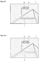
FIGS. 3(a), 3(b), 4(a) and 4(b) illustrate operation examples of the drive assist device 20 in a case where the progressing enabled state of the host vehicle is notified based on the state change of the traffic light S. In this example, the host vehicle stops in front of the stop line L for the signal waiting.
As illustrated in FIG. 3(a), an image I is displayed on the display 21, which indicates a traffic light S that is in a red signal lighting, that is, in a stop display state. As illustrated in FIG. 3(b), when the user designates the traffic light S by touching the region of traffic light S on the image I with a finger F, the traffic light S is set as the recognition target.
Then, as illustrated in FIG. 4(a), a setting frame A or the like that indicates the setting of the recognition target is displayed as superimposed on the traffic light S. It is preferable that the setting of the recognition target becomes effective by the user responding to the message or the like for requesting the confirmation of the setting result. In addition, the stop display state of the traffic light S is detected. Next, as illustrated in FIG. 4(b), when the sign of the traffic light S changes from the red signal to the green signal, the state change of the traffic light S from the stop display state to the progressing display state is detected. Then, for example, the progressing enabled state of the host vehicle is notified via a speaker.
In this way, in a case where the state change from the stop display state to the progressing enabled state of the traffic signal designated by the user is detected, the detection is notified to the user, but, if the user does not designate the traffic signal, the notification is not performed. Therefore, if the user does not want the notification based on the state change of the traffic signal and does not designate the traffic signal, the user does not feel an uncomfortable feeling due to an unnecessary notification.
Furthermore, by starting the state change detection processing of the traffic signal by the user's designation, the user does not need to monitor the traffic signal, and thus, a user's burden for monitoring can be reduced. In addition, by causing the user to designate the traffic signal, it is possible to reduce the processing resource required for the recognition of the traffic signal and to detect the state change of the traffic signal with high accuracy compared to the case of automatic recognition of the traffic signal.
FIGS. 5(a), 5(b), 6(a) and 6(b) illustrate an operation example of the drive assist device 20 in a case where the progressing enabled state of the host vehicle is notified based on the state change of the preceding vehicle V. In this example, the host vehicle is stopped behind the preceding vehicle V for congestion waiting.
As illustrated in FIG. 5(a), an image I is displayed on the display 21, which indicates the preceding vehicle V in a stopped state. As illustrated in FIG. 5(b), when the user designates the preceding vehicle V by touching the preceding vehicle V on the image I with the finger F, the preceding vehicle V is set as the recognition target.
Then, as illustrated in FIG. 6(a), a setting frame A or the like that indicates the setting of the recognition target is displayed as superimposed on the preceding vehicle V. In addition, the preceding vehicle V in the stopped state is detected. Next, as illustrated in FIG. 6(b), when the preceding vehicle V starts, the state change of the preceding vehicle V from stopped state to the starting state is detected. Here, since the display region of the preceding vehicle V on the image I becomes small, the starting of the preceding vehicle V is detected. Then, for example, the progressing enabled state of the host vehicle is notified via a speaker.
In this way, in a case where the state change from the stopped state to the starting state of the preceding vehicle designated by the user is detected, the detection is notified to the user. However, if the user does not designate the preceding vehicle, the notification is not performed. Therefore, if the user does not want the notification based on the state change of the preceding vehicle and does not designate the preceding vehicle, the user does not feel an uncomfortable feeling due to an unnecessary notification. In addition, the notification can be performed in a case where the host vehicle is actually in a progressing enabled state.
Both of the traffic light and the preceding vehicle may be the recognition target. In this case, in a situation of traffic sign waiting or the like, the notification may be performed based on the state change of the traffic signal in a case where the traffic signal can be recognized, and the notification may be performed based on the state change of the preceding vehicle in a case where the traffic signal cannot be recognized. In addition, in a case where the preceding vehicle is designated as the recognition target, a part of the preceding vehicle such as a license plate in which the accuracy of the detection can be ensured may be designated as the recognition target.
Next, a drive assist device 30 in a second embodiment of the present invention will be described with respect to FIG. 7 to FIG. 10. The second embodiment is different from the first embodiment in a point that an image suitable for visually checking the recognition target and an image suitable for detecting the state change of the recognition target are used. Hereinafter, the description that is the same as that in the first embodiment will not be repeated.
FIG. 7 is a block diagram illustrating a configuration of the drive assist device 30 in the second embodiment. A first imaging device (an imaging device) 11, a second imaging device 12 (another imaging device), the detection device 13, and the notification device 14 are connected to the drive assist device 30, and all of those are installed on the vehicles. The functions of the detection device 13 and the notification device 14 are similar to those in the first embodiment.
The first imaging device 11 images around the vehicle, particularly in front of the vehicle, as the first image suitable for visually checking the recognition target, and supplies the imaged first image to the drive assist device 30. The first image is an image representing a situation that is normally captured by the user's eyes.
The second imaging device 12 images around the vehicle, particularly in front of the vehicle, as the second image suitable for detecting the state change of the recognition target, and supplies the imaged second image to the drive assist device 30. The second image is a brightness image, an infrared image, a spectrum image, or the like representing situations that are not normally captured by the user's eyes. At least parts of the imaging ranges of the first imaging device 11 and the second imaging device 12 overlap.
The drive assist device 30 includes a display 21 and an ECU 35. The display 21 displays the first image that is suitable for visual checking of the recognition target.
The ECU 35 includes a setting unit 36, a conversion unit 37, a detection unit 38, and the notification control unit 28. The function of the notification control unit 28 is similar to that in the first embodiment.
The setting unit 36 sets a target on the first image designated by the user as the recognition target. The setting unit 36 acquires position information of the target designated by the user on the first image. The setting unit 36 performs a pattern matching around the position on the second image corresponding to the designated position on the first image and specifies the recognition target based on the position information, and supplies setting information of the specified recognition target to the detection unit 37.
The conversion unit 37 converts the position on the first image to the position on the second image. The conversion unit 37 converts the position considering the installation situations and the imaging conditions of the first imaging device 11 and the second imaging device 12. The conversion unit 37 converts the position information of the designated target on the first image to the corresponding position information on the second image.
The detection unit 38, in a case where the recognition target is set, detects the state change of the recognition target on the second image. The detection unit 38 performs the detection using the second image suitable for detecting the state change of the recognition target. The second image is supplied from the second imaging device 12, and the converted position information is supplied from the conversion unit 37 to the detection unit 38. The detection unit 38 detects the state of the recognition target based on the image information (for example, the brightness, the saturation, the shape, the size, or the like) of the designated recognition target on the second image, and detects the fact that the state change of the recognition target occurred based on the change of the image information. The detection unit 38 supplies the detection result of the state change to the notification control unit 28.
FIG. 8 is a flowchart illustrating an operation of the drive assist device 30. FIG. 9 and FIG. 10 are diagrams explaining the operation of the drive assist device 30. The drive assist device 30 repeatedly executes the processing tasks illustrated in FIG. 8 in the set period.
As illustrated in FIG. 8, the first imaging device 11 and the second imaging device 12 image are in front of the vehicle (S21). The display 21 displays the first image of the front of the vehicle (S22).
When the first image is displayed, the ECU 35 determines whether or not the user designates the target on the first image (S23). Here, in a case where it is determined that the target is designated, the setting unit 36 sets the recognition target on the second image (S24). Then, the display 21 displays the setting result of the recognition target by superimposing on the first image (S25). On the other hand, in a case where it is not determined that the target is designated, the process returns to S21. Accordingly, if the user does not designate the target, subsequent processing such as the notification processing is not performed.
When the recognition target is set, the detection unit 38 detects the state of the recognition target based on the image information of the recognition target on the second image (S26). In addition, the detection unit 38 determines whether or not the state change of the recognition target is detected based on the image information of the recognition target on the second image (S27). In a case where it is determined that the state change is detected, the detection unit 38 supplies the detection result to the notification control unit 28, and the notification device 14 notifies the user of the detection result (S28). On the other hand, in a case where it is not determined that the state change is detected, the process returns to S26.
FIG. 9 and FIG. 10 illustrate operation examples of the drive assist device 30 in a case where the progressing enabled state of the host vehicle is notified based on the state change of the preceding vehicle V. In this example, the host vehicle is stopped behind the preceding vehicle V for the congestion waiting.
As illustrated in FIG. 9(a), a first image I1 which indicates the preceding vehicle V in the stopped state is displayed on the display 21. As illustrated in FIG. 9(b), when the user designates the preceding vehicle V by touching the preceding vehicle V on the first image I1 with the finger F, the preceding vehicle V is set as the recognition target. Here, in designating the preceding vehicle V, since the first image I1 suitable for visual checking is used, the preceding vehicle V can easily be designated.
Then, as illustrated in FIG. 10(a), a setting frame A or the like that indicates the setting of the recognition target on the first image I1 is displayed as superimposed on the preceding vehicle V. In addition, the preceding vehicle V in the stopped state is detected. Next, as illustrated in FIG. 10(b), when the preceding vehicle V starts, the state change of the preceding vehicle V from the stopped state to the starting state on the second image I2 is detected. The second image I2 is not displayed on the display 21. Here, in detecting the state change of the preceding vehicle V, since the second image I2 suitable for detecting the state change such as the brightness image or the like is used, it is possible to detect the state change of the preceding vehicle V with high accuracy. Then, the progressing enabled state of the host vehicle can be notified via, for example, the speaker.
In this way, it is possible to easily designate the recognition target and improve the detection accuracy in detecting the state change. In the above description, a case of detecting the state change of the preceding vehicle using the second image is described. However, the state change of the traffic light S may be detected.
As described above, according to the drive assist devices 20 and 30, since the detection result is notified to the user in a case where the state change of the recognition target set by the user's designation is detected, if the user does not designate the recognition target, the notification is not performed. Therefore, it is possible to suppress the uncomfortable feeling to the user due to the unnecessary notification.
In addition, by performing the notification in a case where the state change of the traffic signal from the stop display to the progressing display is detected, the progressing enabled state of the host vehicle can appropriately be notified based on the state change of the traffic signal.
In addition, by performing the notification in a case where the state change of the preceding vehicle from the stopped state to the starting state is detected, the progressing enabled state of the host vehicle can appropriately be notified based on the state change of the preceding vehicle. In addition, the notification can be performed in a case where the host vehicle is actually in a progressing enabled state.
In addition, by using the image suitable for visually checking the recognition target and the image suitable for detecting the state change of the recognition target, it is possible to easily designate the recognition target and improve the detection accuracy in detecting the state change.
In addition, by not displaying the image in a case where the moving speed of the vehicle exceeds the threshold value, it is possible to suppress the power consumption required for the unnecessary image displaying. In addition, it is possible to suppress the hindrance to the driving operation caused by the unnecessary image displaying.
The embodiment described above is the best embodiment of the drive assist devices 20 and 30 according to the present invention, and the drive assist devices 20 and 30 are not limited the above-described embodiments. The drive assist devices 20 and 30 according to the present invention may be modified without departing from the scope of the invention described in the Claims, or may be the devices applied to other devices.
For example, in the embodiment described above, the progressing enabled state of the host vehicle is notified with at least one of the traffic light and the preceding vehicle as the recognition target. However, the progressing enabled state of the host vehicle may be notified with another object as the recognition target. In addition, other states such as a parking enabled state or a retreating enabled state of the host vehicle may be notified, instead of the progressing enabled state of the host vehicle.
In addition, as a detection device, the most suitable device may be selected according to the recognition target. For example, if the recognition target is limited to a vehicle, by using a display that displays computer graphics together with using the radar as a detection device, the similar effect can be obtained. Alternatively, a laser scanner capable of three-dimensional measuring may be used as a detection device.
In addition, if the recognition target is limited to a vehicle, the recognition target may be set by acquiring a voice that reads a number on a license plate by the voice recognition device.

Claims (9)

What is claimed is:
1. A drive assist device for a vehicle comprising:
a camera configured to capture an environment around the vehicle;
a display configured to display the captured environment;
a target setter configured to determine whether a user has designated a target region of the captured environment on the display, and when the target region is designated by the user, recognize an object on the target region that is capable of a state change, as a corresponding target object;
a detector configured to detect whether a state change has occurred of the recognized corresponding target object on the display without detecting whether a state change has occurred of other objects that are not recognized corresponding target object on the display, wherein the detector detects whether the state change has occurred based on a change of image information; and
a notification controller configured to control a notification to the user when the state change of the recognized corresponding target object is detected.
2. The drive assist device according to claim 1,
wherein the target region is a traffic light, and the recognized corresponding target object of the target region is a signal of the traffic light, wherein the state change of the signal is when a stop signal changes to a go signal, and
wherein the detector detects the state change of the traffic light when the signal changes from the stop signal to the go signal.
3. The drive assist device according to claim 1,
wherein the recognized corresponding target object is a preceding vehicle, wherein the state change of the preceding vehicle is when the preceding vehicle changes from a stopped state to a starting state, and
wherein the detector detects the state change of the preceding vehicle when the preceding vehicle changes from the stopped state to the starting state.
4. The drive assist device according to claim 1, further comprising:
a conversion unit that converts a position on a first image suitable for visually checking the recognized corresponding target object imaged by the camera to a position corresponding to a position on a second image suitable for detecting the state change of the recognized corresponding target object imaged by another camera installed on the vehicle,
wherein the display displays the first image,
wherein the target setter sets the target region by the user on the first image as a recognized corresponding target object on the second image, and
wherein, in a case where the recognized corresponding target object is set, the detector detects the state change of the recognized corresponding target object on the second image.
5. The drive assist device according to claim 1, further comprising:
a speed detection unit that detects a moving speed of the vehicle,
wherein, in a case where the moving speed exceeds a threshold value, the display does not display the captured environment.
6. The drive assist device according to claim 1, wherein the target setter enables the setting of the recognized corresponding target object after the user confirms a setting result of the recognized corresponding target object.
7. The drive assist device according to claim 1, wherein the target setter enables the setting of the recognized corresponding target object after the user responds to a message for requesting confirmation of a setting result.
8. A drive assist device for a vehicle comprising:
a camera configured to capture an environment around the vehicle;
a display configured to display the captured environment; and
an electronic control unit programmed to:
set a target region on the display when the target region is designated by a user:
recognize an object that is capable of changing state on the target region as a corresponding target object;
detect a change in a state of only the recognized corresponding target object without detecting a change in a state of other targets that are not recognized corresponding target objects, wherein the detector detects whether the state change has occurred based on a change of image information; and
notify the user, using visual, auditory or tactual information, of the detected change in the state of the recognized corresponding target object.
9. The drive assist device according to claim 1, wherein the recognized corresponding target object is one of a plurality of objects from which the user selects on the display of the captured environment around the vehicle when the vehicle is stopped, so that the change of state for only the recognized corresponding target object from amongst the plurality of objects is detected for notification to the user.
US16/185,698 2012-08-01 2018-11-09 Drive assist device Active US10867515B2 (en)

Priority Applications (3)

Application Number Priority Date Filing Date Title
US16/185,698 US10867515B2 (en) 2012-08-01 2018-11-09 Drive assist device
US17/094,397 US11205348B2 (en) 2012-08-01 2020-11-10 Drive assist device
US17/526,482 US11688162B2 (en) 2012-08-01 2021-11-15 Drive assist device

Applications Claiming Priority (3)

Application Number Priority Date Filing Date Title
PCT/JP2012/069608 WO2014020727A1 (en) 2012-08-01 2012-08-01 Drive assist device
US201514418514A 2015-02-23 2015-02-23
US16/185,698 US10867515B2 (en) 2012-08-01 2018-11-09 Drive assist device

Related Parent Applications (3)

Application Number Title Priority Date Filing Date
PCT/JP2012/069608 Continuation WO2014020727A1 (en) 2012-08-01 2012-08-01 Drive assist device
US14/418,514 Continuation US10163348B2 (en) 2012-08-01 2012-08-01 Drive assist device
US201514418514A Continuation 2012-08-01 2015-02-23

Related Child Applications (1)

Application Number Title Priority Date Filing Date
US17/094,397 Continuation US11205348B2 (en) 2012-08-01 2020-11-10 Drive assist device

Publications (2)

Publication Number Publication Date
US20190080605A1 US20190080605A1 (en) 2019-03-14
US10867515B2 true US10867515B2 (en) 2020-12-15

Family

ID=50027457

Family Applications (4)

Application Number Title Priority Date Filing Date
US14/418,514 Active 2033-07-15 US10163348B2 (en) 2012-08-01 2012-08-01 Drive assist device
US16/185,698 Active US10867515B2 (en) 2012-08-01 2018-11-09 Drive assist device
US17/094,397 Active US11205348B2 (en) 2012-08-01 2020-11-10 Drive assist device
US17/526,482 Active US11688162B2 (en) 2012-08-01 2021-11-15 Drive assist device

Family Applications Before (1)

Application Number Title Priority Date Filing Date
US14/418,514 Active 2033-07-15 US10163348B2 (en) 2012-08-01 2012-08-01 Drive assist device

Family Applications After (2)

Application Number Title Priority Date Filing Date
US17/094,397 Active US11205348B2 (en) 2012-08-01 2020-11-10 Drive assist device
US17/526,482 Active US11688162B2 (en) 2012-08-01 2021-11-15 Drive assist device

Country Status (5)

Country Link
US (4) US10163348B2 (en)
JP (1) JP5907268B2 (en)
CN (1) CN104508720B (en)
DE (1) DE112012006761T5 (en)
WO (1) WO2014020727A1 (en)

Cited By (1)

* Cited by examiner, † Cited by third party
Publication number Priority date Publication date Assignee Title
US11688162B2 (en) 2012-08-01 2023-06-27 Toyota Jidosha Kabushiki Kaisha Drive assist device

Families Citing this family (15)

* Cited by examiner, † Cited by third party
Publication number Priority date Publication date Assignee Title
JP6418089B2 (en) * 2015-07-08 2018-11-07 オムロン株式会社 Image processing apparatus, traffic management system including the same, and image processing method
CN106611512B (en) * 2015-10-23 2020-02-07 杭州海康威视数字技术股份有限公司 Method, device and system for processing starting of front vehicle
US20170203691A1 (en) * 2016-01-20 2017-07-20 Yu-Chen Chou Vehicle of no blind spot
JP6720729B2 (en) * 2016-06-28 2020-07-08 アイシン精機株式会社 Display controller
CN106408681A (en) * 2016-08-31 2017-02-15 苏州统购信息科技有限公司 Intelligent driving monitoring method
US10366286B2 (en) 2016-12-13 2019-07-30 Google Llc Detection of traffic light signal changes
CN107331181B (en) * 2016-12-29 2020-03-24 佛山科学技术学院 Intelligent reminding method and system for vehicle following
US10650257B2 (en) 2017-02-09 2020-05-12 SMR Patents S.à.r.l. Method and device for identifying the signaling state of at least one signaling device
DE102017102593A1 (en) 2017-02-09 2018-08-09 SMR Patents S.à.r.l. Method and device for detecting the signaling state of at least one signaling device
JP2019212187A (en) * 2018-06-08 2019-12-12 スズキ株式会社 Vehicle drive assist device
GB2579857B (en) * 2018-12-18 2022-10-19 Jaguar Land Rover Ltd Behaviour event monitoring system for a vehicle
KR20210019630A (en) * 2019-08-12 2021-02-23 현대자동차주식회사 Interactive autonomous driving system
CN112349101B (en) * 2021-01-08 2021-04-27 深圳裹动智驾科技有限公司 High-precision map generation method, and method and system for identifying traffic lights
DE102021103732A1 (en) 2021-02-17 2022-08-18 Cariad Se Driver assistance system, motor vehicle and method for automatic longitudinal guidance of a motor vehicle
WO2022178802A1 (en) * 2021-02-26 2022-09-01 华为技术有限公司 Leading vehicle departure detection method and apparatus

Citations (32)

* Cited by examiner, † Cited by third party
Publication number Priority date Publication date Assignee Title
DE19941477A1 (en) 1999-09-01 2001-03-22 Bosch Gmbh Robert Navigation device for a land vehicle
US6587593B1 (en) 1998-04-28 2003-07-01 Sharp Kabushiki Kaisha Image processing device and image processing method
US20040042070A1 (en) 2002-08-27 2004-03-04 Koito Manufacturing Co., Ltd Vehicular infrared light radiating lamp
US20040204157A1 (en) 2002-06-06 2004-10-14 Donald Remboski Driver information interface and method of managing driver information
US20050248445A1 (en) 2004-05-06 2005-11-10 Mitsubishi Denki Kabushiki Kaisha Alarm device for vehicle
US20060095192A1 (en) 2002-11-02 2006-05-04 Werner Uhler Device for adaptive distance and speed control with jerk limitation
US20070217780A1 (en) 2006-03-17 2007-09-20 Shinichiro Hirooka Object detection apparatus
US20070222638A1 (en) 2006-03-17 2007-09-27 Yang Chen Location based vehicle traffic signal alert system
US20070276581A1 (en) 2006-05-25 2007-11-29 Bae Hong S Alerting a vehicle operator to traffic movement
US20070290875A1 (en) 2006-06-08 2007-12-20 International Business Machines Corporation Interactive wireless interface
US20080211779A1 (en) * 1994-08-15 2008-09-04 Pryor Timothy R Control systems employing novel physical controls and touch screens
US20080226126A1 (en) 2005-01-31 2008-09-18 Yoshinori Ohno Object-Tracking Apparatus, Microscope System, and Object-Tracking Program
US20080239078A1 (en) 2006-11-21 2008-10-02 Harman Becker Automotive Systems Gmbh Video image presentation system
US20090174573A1 (en) * 2008-01-04 2009-07-09 Smith Alexander E Method and apparatus to improve vehicle situational awareness at intersections
WO2009101692A1 (en) 2008-02-14 2009-08-20 Pioneer Corporation Forward looking device, forward looking method and forward looking program
US20090303077A1 (en) 2006-03-06 2009-12-10 Hirohisa Onome Image Processing System and Method
US20100109908A1 (en) 2008-10-30 2010-05-06 Aisin Aw Co., Ltd. Safe driving evaluation system and safe driving evaluation program
US20100141476A1 (en) 2007-01-04 2010-06-10 Continental Automotive Gmbh Driver assistance system for traffic sign recognition
US20100153844A1 (en) 2008-12-15 2010-06-17 Verizon Data Services Llc Three dimensional icon stacks
JP2010173530A (en) 2009-01-30 2010-08-12 Toyota Motor Corp Driving support device
US20100253594A1 (en) * 2009-04-02 2010-10-07 Gm Global Technology Operations, Inc. Peripheral salient feature enhancement on full-windshield head-up display
US20110010020A1 (en) 2009-07-09 2011-01-13 Denso Corporation Object specifying device and vehicle control apparatus having the device
US20110050482A1 (en) 2008-09-05 2011-03-03 Toyota Jidosha Kabushiki Kaisha Object detecting device
US20110115646A1 (en) 2009-03-11 2011-05-19 Toyota Jidosha Kabushiki Kaisha Driving supporting device
US20110144908A1 (en) 2009-12-10 2011-06-16 Dorothy Cheong Method of locating nearby low priced items using a personal navigation device
US20110182475A1 (en) * 2010-01-22 2011-07-28 Google Inc. Traffic signal mapping and detection
US20120069180A1 (en) 2009-05-26 2012-03-22 Panasonic Electric Works Co., Ltd. Information presentation apparatus
DE102011087459A1 (en) 2011-11-30 2013-06-06 Bayerische Motoren Werke Aktiengesellschaft Driver assistance system for motor car, has user interface the enables the driver to execute several functions of assistance system as function of specified objects in environment
US20130207805A1 (en) 2012-02-09 2013-08-15 Denso Corporation Inattentive state determination apparatus and method of determining inattentive state
JP2013218571A (en) 2012-04-10 2013-10-24 Toyota Motor Corp Image recognition device and driving support device
US20140161312A1 (en) 2012-12-12 2014-06-12 Canon Kabushiki Kaisha Setting apparatus, image processing apparatus, control method of setting apparatus, and storage medium
US20150375754A1 (en) 2012-06-26 2015-12-31 Microsoft Technology Licensing, Llc Ambient Vehicle and Pedestrian State Detection for Device Notification

Family Cites Families (13)

* Cited by examiner, † Cited by third party
Publication number Priority date Publication date Assignee Title
DE102005013920B4 (en) * 2004-03-26 2007-12-13 Mitsubishi Jidosha Kogyo K.K. Front view monitoring apparatus
JP2006137274A (en) * 2004-11-11 2006-06-01 Nissan Motor Co Ltd Operation assisting device, and driving assisting method
EP1916846B1 (en) * 2005-08-02 2016-09-14 Nissan Motor Company Limited Device and method for monitoring vehicle surroundings
JP2008283502A (en) * 2007-05-11 2008-11-20 Casio Comput Co Ltd Digital camera, photographing control method and photographing control program
JP2009003595A (en) * 2007-06-20 2009-01-08 Pioneer Electronic Corp Navigation unit, drive support unit, traffic signal state notification method and program, and drive support method and program
JP4986069B2 (en) * 2008-03-19 2012-07-25 マツダ株式会社 Ambient monitoring device for vehicles
JP2009230560A (en) * 2008-03-24 2009-10-08 Casio Comput Co Ltd Signal recognition device and signal recognition processing program
JP4900326B2 (en) * 2008-06-10 2012-03-21 日産自動車株式会社 Parking assistance device and parking assistance method
JP5087051B2 (en) * 2009-07-02 2012-11-28 富士通テン株式会社 Image generating apparatus and image display system
JP5251947B2 (en) * 2010-09-17 2013-07-31 日産自動車株式会社 Image display device for vehicle
KR20130076215A (en) * 2011-12-28 2013-07-08 현대자동차주식회사 Device for alarming image change of vehicle
DE112012006761T5 (en) 2012-08-01 2015-04-30 Toyota Jidosha Kabushiki Kaisha Driving assistance device
JP2015035704A (en) * 2013-08-08 2015-02-19 株式会社東芝 Detector, detection method and detection program

Patent Citations (34)

* Cited by examiner, † Cited by third party
Publication number Priority date Publication date Assignee Title
US20080211779A1 (en) * 1994-08-15 2008-09-04 Pryor Timothy R Control systems employing novel physical controls and touch screens
US6587593B1 (en) 1998-04-28 2003-07-01 Sharp Kabushiki Kaisha Image processing device and image processing method
US6556917B1 (en) 1999-09-01 2003-04-29 Robert Bosch Gmbh Navigation device for a land-bound vehicle
DE19941477A1 (en) 1999-09-01 2001-03-22 Bosch Gmbh Robert Navigation device for a land vehicle
US20040204157A1 (en) 2002-06-06 2004-10-14 Donald Remboski Driver information interface and method of managing driver information
US20040042070A1 (en) 2002-08-27 2004-03-04 Koito Manufacturing Co., Ltd Vehicular infrared light radiating lamp
US20060095192A1 (en) 2002-11-02 2006-05-04 Werner Uhler Device for adaptive distance and speed control with jerk limitation
US20050248445A1 (en) 2004-05-06 2005-11-10 Mitsubishi Denki Kabushiki Kaisha Alarm device for vehicle
US20080226126A1 (en) 2005-01-31 2008-09-18 Yoshinori Ohno Object-Tracking Apparatus, Microscope System, and Object-Tracking Program
US20090303077A1 (en) 2006-03-06 2009-12-10 Hirohisa Onome Image Processing System and Method
US20070222638A1 (en) 2006-03-17 2007-09-27 Yang Chen Location based vehicle traffic signal alert system
US20070217780A1 (en) 2006-03-17 2007-09-20 Shinichiro Hirooka Object detection apparatus
US20070276581A1 (en) 2006-05-25 2007-11-29 Bae Hong S Alerting a vehicle operator to traffic movement
US20070290875A1 (en) 2006-06-08 2007-12-20 International Business Machines Corporation Interactive wireless interface
US20080239078A1 (en) 2006-11-21 2008-10-02 Harman Becker Automotive Systems Gmbh Video image presentation system
US20100141476A1 (en) 2007-01-04 2010-06-10 Continental Automotive Gmbh Driver assistance system for traffic sign recognition
US20090174573A1 (en) * 2008-01-04 2009-07-09 Smith Alexander E Method and apparatus to improve vehicle situational awareness at intersections
WO2009101692A1 (en) 2008-02-14 2009-08-20 Pioneer Corporation Forward looking device, forward looking method and forward looking program
US20110050482A1 (en) 2008-09-05 2011-03-03 Toyota Jidosha Kabushiki Kaisha Object detecting device
US20100109908A1 (en) 2008-10-30 2010-05-06 Aisin Aw Co., Ltd. Safe driving evaluation system and safe driving evaluation program
US20100153844A1 (en) 2008-12-15 2010-06-17 Verizon Data Services Llc Three dimensional icon stacks
JP2010173530A (en) 2009-01-30 2010-08-12 Toyota Motor Corp Driving support device
US20110115646A1 (en) 2009-03-11 2011-05-19 Toyota Jidosha Kabushiki Kaisha Driving supporting device
US20100253594A1 (en) * 2009-04-02 2010-10-07 Gm Global Technology Operations, Inc. Peripheral salient feature enhancement on full-windshield head-up display
US20120069180A1 (en) 2009-05-26 2012-03-22 Panasonic Electric Works Co., Ltd. Information presentation apparatus
CN101947956A (en) 2009-07-09 2011-01-19 株式会社电装 Object specified device and have a vehicle control apparatus of this device
US20110010020A1 (en) 2009-07-09 2011-01-13 Denso Corporation Object specifying device and vehicle control apparatus having the device
US20110144908A1 (en) 2009-12-10 2011-06-16 Dorothy Cheong Method of locating nearby low priced items using a personal navigation device
US20110182475A1 (en) * 2010-01-22 2011-07-28 Google Inc. Traffic signal mapping and detection
DE102011087459A1 (en) 2011-11-30 2013-06-06 Bayerische Motoren Werke Aktiengesellschaft Driver assistance system for motor car, has user interface the enables the driver to execute several functions of assistance system as function of specified objects in environment
US20130207805A1 (en) 2012-02-09 2013-08-15 Denso Corporation Inattentive state determination apparatus and method of determining inattentive state
JP2013218571A (en) 2012-04-10 2013-10-24 Toyota Motor Corp Image recognition device and driving support device
US20150375754A1 (en) 2012-06-26 2015-12-31 Microsoft Technology Licensing, Llc Ambient Vehicle and Pedestrian State Detection for Device Notification
US20140161312A1 (en) 2012-12-12 2014-06-12 Canon Kabushiki Kaisha Setting apparatus, image processing apparatus, control method of setting apparatus, and storage medium

Cited By (1)

* Cited by examiner, † Cited by third party
Publication number Priority date Publication date Assignee Title
US11688162B2 (en) 2012-08-01 2023-06-27 Toyota Jidosha Kabushiki Kaisha Drive assist device

Also Published As

Publication number Publication date
JP5907268B2 (en) 2016-04-26
US11205348B2 (en) 2021-12-21
CN104508720A (en) 2015-04-08
US20220076577A1 (en) 2022-03-10
JPWO2014020727A1 (en) 2016-07-11
US10163348B2 (en) 2018-12-25
US20190080605A1 (en) 2019-03-14
DE112012006761T5 (en) 2015-04-30
WO2014020727A1 (en) 2014-02-06
CN104508720B (en) 2016-09-07
US20150187214A1 (en) 2015-07-02
US11688162B2 (en) 2023-06-27
US20210056850A1 (en) 2021-02-25

Similar Documents

Publication Publication Date Title
US10867515B2 (en) Drive assist device
EP3351417B1 (en) Display apparatus for vehicle and display method for vehicle
CN106470877B (en) Vehicle display device and vehicle display method
EP3005228B1 (en) Information processing device, approaching object notification method, and program
WO2016067544A1 (en) Vehicle-mounted attention-attracting system and notification control device
JP6562079B2 (en) Display device for vehicle and display method for vehicle
CN106660495B (en) Vehicle display device and vehicle display method
WO2015015919A1 (en) Vehicle periphery monitoring device
TWI522257B (en) Vehicle safety system and operating method thereof
JP2010111260A (en) Vehicle speed control device
JP2013218571A (en) Image recognition device and driving support device
JP2014149640A (en) Gesture operation device and gesture operation program
WO2014103217A1 (en) Operation device and operation detection method
CN111645674B (en) Vehicle control device
JP5939170B2 (en) Object approach notification system
JP5271511B2 (en) Driving support device and image display device
CN111556281A (en) Vehicle safety system and operation method thereof
JP5192007B2 (en) Vehicle periphery monitoring device
US11807264B2 (en) Driving assistance apparatus, driving assistance method, and medium
JP6365409B2 (en) Image display device for vehicle driver
JP5529097B2 (en) Vehicle driving support device
JP2009110065A (en) Driving support device
JP2010087861A (en) Dead-angle image display and dead-angle image display method
JP2018185764A (en) Light presentation device

Legal Events

Date Code Title Description
FEPP Fee payment procedure

Free format text: ENTITY STATUS SET TO UNDISCOUNTED (ORIGINAL EVENT CODE: BIG.); ENTITY STATUS OF PATENT OWNER: LARGE ENTITY

STPP Information on status: patent application and granting procedure in general

Free format text: APPLICATION DISPATCHED FROM PREEXAM, NOT YET DOCKETED

STPP Information on status: patent application and granting procedure in general

Free format text: DOCKETED NEW CASE - READY FOR EXAMINATION

STPP Information on status: patent application and granting procedure in general

Free format text: NON FINAL ACTION MAILED

STPP Information on status: patent application and granting procedure in general

Free format text: RESPONSE TO NON-FINAL OFFICE ACTION ENTERED AND FORWARDED TO EXAMINER

STPP Information on status: patent application and granting procedure in general

Free format text: DOCKETED NEW CASE - READY FOR EXAMINATION

FEPP Fee payment procedure

Free format text: PETITION RELATED TO MAINTENANCE FEES GRANTED (ORIGINAL EVENT CODE: PTGR); ENTITY STATUS OF PATENT OWNER: LARGE ENTITY

STPP Information on status: patent application and granting procedure in general

Free format text: PUBLICATIONS -- ISSUE FEE PAYMENT VERIFIED

STCF Information on status: patent grant

Free format text: PATENTED CASE