US10866335B2 - Formation clay typing from electromagnetic measurements - Google Patents
Formation clay typing from electromagnetic measurements Download PDFInfo
- Publication number
- US10866335B2 US10866335B2 US16/041,454 US201816041454A US10866335B2 US 10866335 B2 US10866335 B2 US 10866335B2 US 201816041454 A US201816041454 A US 201816041454A US 10866335 B2 US10866335 B2 US 10866335B2
- Authority
- US
- United States
- Prior art keywords
- representing
- formation
- borehole
- clay
- location
- Prior art date
- Legal status (The legal status is an assumption and is not a legal conclusion. Google has not performed a legal analysis and makes no representation as to the accuracy of the status listed.)
- Active, expires
Links
Images


Classifications
-
- G—PHYSICS
- G01—MEASURING; TESTING
- G01V—GEOPHYSICS; GRAVITATIONAL MEASUREMENTS; DETECTING MASSES OR OBJECTS; TAGS
- G01V3/00—Electric or magnetic prospecting or detecting; Measuring magnetic field characteristics of the earth, e.g. declination, deviation
- G01V3/18—Electric or magnetic prospecting or detecting; Measuring magnetic field characteristics of the earth, e.g. declination, deviation specially adapted for well-logging
- G01V3/30—Electric or magnetic prospecting or detecting; Measuring magnetic field characteristics of the earth, e.g. declination, deviation specially adapted for well-logging operating with electromagnetic waves
-
- G—PHYSICS
- G01—MEASURING; TESTING
- G01N—INVESTIGATING OR ANALYSING MATERIALS BY DETERMINING THEIR CHEMICAL OR PHYSICAL PROPERTIES
- G01N24/00—Investigating or analyzing materials by the use of nuclear magnetic resonance, electron paramagnetic resonance or other spin effects
- G01N24/08—Investigating or analyzing materials by the use of nuclear magnetic resonance, electron paramagnetic resonance or other spin effects by using nuclear magnetic resonance
- G01N24/081—Making measurements of geologic samples, e.g. measurements of moisture, pH, porosity, permeability, tortuosity or viscosity
-
- G—PHYSICS
- G01—MEASURING; TESTING
- G01V—GEOPHYSICS; GRAVITATIONAL MEASUREMENTS; DETECTING MASSES OR OBJECTS; TAGS
- G01V3/00—Electric or magnetic prospecting or detecting; Measuring magnetic field characteristics of the earth, e.g. declination, deviation
- G01V3/18—Electric or magnetic prospecting or detecting; Measuring magnetic field characteristics of the earth, e.g. declination, deviation specially adapted for well-logging
- G01V3/32—Electric or magnetic prospecting or detecting; Measuring magnetic field characteristics of the earth, e.g. declination, deviation specially adapted for well-logging operating with electron or nuclear magnetic resonance
-
- G—PHYSICS
- G01—MEASURING; TESTING
- G01V—GEOPHYSICS; GRAVITATIONAL MEASUREMENTS; DETECTING MASSES OR OBJECTS; TAGS
- G01V5/00—Prospecting or detecting by the use of nuclear radiation, e.g. of natural or induced radioactivity
- G01V5/04—Prospecting or detecting by the use of nuclear radiation, e.g. of natural or induced radioactivity specially adapted for well-logging
- G01V5/08—Prospecting or detecting by the use of nuclear radiation, e.g. of natural or induced radioactivity specially adapted for well-logging using primary nuclear radiation sources or X-rays
- G01V5/10—Prospecting or detecting by the use of nuclear radiation, e.g. of natural or induced radioactivity specially adapted for well-logging using primary nuclear radiation sources or X-rays using neutron sources
Definitions
- the subject disclosure relates to formation evaluation. More particularly, the subject disclosure relates to methods of using array electromagnetic tools in determining the type of clay contained in a formation.
- clays in formations containing hydrocarbon reservoirs can significantly impact estimates of reserves and producibility.
- the presence of clay minerals complicates determinations of porosity and saturation, and it is also known that permeability is very sensitive to even low levels of specific clay minerals in the pore space, such as illite. Without specific knowledge of the clay minerals present, there is a risk of impairing the permeability of a reservoir through the introduction of improper fluids during production.
- NMR nuclear magnetic resonance
- a density-neutron log cross-plot technique has been used as a method for qualitatively determining clay content in oil and water saturated shaly sands. See Bhuyan, K.
- array electromagnetic (AEM) measurements are used to identify some of the most common clays encountered in petroleum reservoirs.
- An array electromagnetic tool is run in a borehole, and resulting signals are processed to provide real and/or imaginary conductivity components, ⁇ R* and ⁇ I* .
- the real and/or imaginary conductivity components are compared to a corresponding representative conductivity component of a plurality of different clay groups, and a determination of clay type in the formation is made therefrom.
- FIG. 1 is a diagram showing the interfacial polarization of clay minerals with electrical double layers
- FIG. 2 is a workflow of one embodiment for clay typing
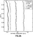
- FIGS. 3 a and 3 b are plots of in-phase conductivity and out-of-phase conductivity respectively for multiple clay groups and for field data;
- FIG. 4 is a diagram showing an array induction logging tool in a borehole.
- array electromagnetic (AEM) measurements are used to identify some of the most common clays encountered in petroleum reservoirs.
- AEM measurements are acquired in almost every vertical and slightly deviated well that is drilled.
- Tools such as the Array Induction Tool® (AIT—a trademark of Schlumberger) discussed hereinafter with reference to FIG. 4 , are often used to obtain the AEM measurements.
- various clay minerals can be lumped, on the basis of molecular structure and composition, into four most commonly encountered and representative groups in petroleum reservoirs: kaolinite, illite, chlorite and smectite.
- each clay group impacts formation conductivity differently, the fundamental mechanism is similar.
- the surface of a clay mineral grain is exposed to electrolytes, it acquires charges due to ionic adsorption, protonation/deprotonation of the hydroxyl groups, and dissociation of other potentially active surface groups. See, Leroy, P., and A. Revil, “A triple layer model of the surface electrochemical properties of clay minerals”, Journal of Colloid and Interface Science, 270, 371-380 (2004).
- the double layer develops a counter ion cloud and diffused-charge distributions around host-inclusion interfaces.
- Dynamics of accumulation/depletion of charge concentrations around host-inclusion interfaces influence the magnitude and phase of the EM response of a reservoir formation containing clay minerals.
- this total conductivity depends on conductivity of pore fluid, fluid saturation, ion mobility and cation exchange capacity (CEC) of clay inclusions.
- CEC cation exchange capacity
- the in-phase and quadrature components have different relationships with these parameters (see, Revil, A., “Spectral induced polarization of shaly sands: Influence of the electrical double layer”, Water Resources Research , Vol 48, W02517 (2012)), such that
- ⁇ R S w n 0 F ⁇ [ ⁇ w + 2 ⁇ ⁇ m 0 ⁇ ⁇ + ⁇ g ⁇ CEC 3 ⁇ ( F ⁇ ⁇ 1 ) ] ( 2 )
- ⁇ w represents formation water conductivity
- ⁇ g represents matrix grain density
- ⁇ + is the mobility of a counterion in the formation fluid
- S w is the water saturation, and no is a saturation exponent
- ⁇ I 2 ⁇ 3 ⁇ + s f ⁇ g S w n o -1 CEC (3) where f is fraction of counterion in the Stern layer, ⁇ + s is mobility of the counterion within Stern layer.
- in-phase and quadrature (out-of-phase) conductivity it is desirable to have a prior knowledge of seven petrophysical parameters (m 0 , n 0 , ⁇ , ⁇ g , ⁇ w , S w , CEC) and three electrochemical parameters (f, ⁇ + , ⁇ + s ).
- CEC may be considered a key parameter to distinguish amongst different clays, because each clay group has its own CEC values.
- the remaining petrophysical parameters are routinely estimated during traditional log analysis.
- the electrochemical parameters may be defined in lab experiments or through log analysis.
- a workflow for clay typing is provided according to one embodiment.
- an array electromagnetic tool such as the AIT tool is run in a borehole traversing a formation and raw data is collected.
- estimated real and/or imaginary conductivity components, ⁇ R* and ⁇ I* are computed from raw AIT data.
- the estimated real and/or imaginary conductivity components are compared to real and/or imaginary conductivity components representative of different clay groups.
- this comparison may be accomplished by plotting the real and/or imaginary conductivity component values as a function of depth on one or more plots which also provide reference curves or values (logs) for the real and imaginary conductivity component values of different clay groups (as will be discussed hereinafter with respect to FIGS. 3 a and 3 b ).
- clay type determinations may be made at 140 . This is particularly the case where the calculated real and/or imaginary conductivity components correspond to either a maximum value or a minimum value (corresponding to smectite or chlorite respectively).
- the calculated real and/or imaginary conductivity components may correspond to values that represent kaolinite or illite.
- the computed ⁇ R* and ⁇ I* estimated values may be different than the reference curves for any particular clay group, and the quantities of different clays may be computed as discussed hereinafter.
- a workflow for generating reference curves for the real and imaginary conductivity component values of different clays is also seen.
- multiple tools such as a neutron-density logging tool, NMR tool and a dielectric tool are run in the borehole traversing a formation over an interval of interest and log analyses are utilized to provide estimates for above-mentioned petrophysical parameters ( ⁇ , ⁇ g , ⁇ w , S w ) for the logged interval.
- Rock electrical properties m 0 and n 0 may be obtained at 156 from lab core analysis or from specialized logs such as dielectric log data for the interval of interest.
- lab experiments may be run to estimate electrochemical parameters f, ⁇ + , ⁇ + s under a lab condition most relevant to the field environment.
- logs such as Litho Scanner, or even a gamma ray log and density-neutron logs, may be used to obtain an estimation for clay volume over the interval of interest.
- Known CEC values from four clay groups (kaolinite, illite, chlorite and smectite) are inputs at 161 .
- reference ⁇ R and ⁇ I values are computed at 163 utilizing equations (2) and (3), with multiple real and imaginary conductivity reference values being calculated for each location under an assumption that the entire clay volume at that location has only one kind of clay.
- the multiple reference values may then be plotted at 167 as logs (reference curves) for the interval of interest.
- 3 a and 3 b are curves (logs) generated by having run AIT logs and collecting raw data (at 110 ), and estimating (at 120 ) the real and/or imaginary conductivity components, ⁇ R* and ⁇ I* along the same interval of interest.
- a comparison (step 130 ) of the estimated values generated using the AEM measurements of the AIT tool and the reference curves is seen in both FIG. 3 a and FIG. 3 b .
- the estimated data log tracks the chlorite log closely, suggesting that the clay in the formation over the interval of interest is likely to be chlorite (i.e., the determination of step 140 ).
- the chlorite determination was confirmed by an elemental analysis which revealed that at least 85% of the clay in the interval of interest was chlorite.
- V sh wet shale volume
- V sh wet shale volume
- Shales are dominated by clays and other fine particle minerals such as calcite, feldspar, etc.
- V dry_cl data is available from either core analysis such as x-ray diffraction measurement or from specialized logs such as LithoScanner, then localized correlations can be established between V dry_cl (from core or from specialized logs) and V dry_sh from conventional logs. With such correlations, V dry_cl can be obtained from V dry_sh .
- the W dry_cl can be calculated from V dry_cl using the following formula;
- W dry_cl ⁇ dry_cl ⁇ V dry_cl ⁇ matrix ⁇ ( 1 ⁇ - tatal ) ( 5 )
- ⁇ total is the formation total porosity
- ⁇ matrix is matrix density
- ⁇ dry_cl is density of dry clay. Since the CEC values (CEC i ) for the four clay groups are known, and the total CEC can be obtained from AIT log processing (using the workflow in FIG. 2 ), equation (4) may be used to find the relative weight fraction of each dry clay mineral in the clay mix (w i ) by using least square algorithm to fit the known data to the ⁇ R* curve (and/or the ⁇ I* curve).
- FIG. 4 a diagram is provided of an array induction tool 418 deployed in a wellbore 430 traversing a formation 400 .
- the array induction tool 418 is coupled to a processing unit 450 configured to determine the presence of particular clay minerals, according to some embodiments. More particularly, FIG. 4 shows a wireline truck 410 deploying wireline cable 412 into well 430 at a wellsite 420 .
- the array induction tool 418 is disposed on the end of the cable 412 in the subterranean rock formation 400 .
- formation 400 is a clay-containing reservoir formation such as a shaly sand formation.
- the array induction tool 418 is an array induction tool such as Schlumberger's Array Induction Imager Tool which includes an array induction coil transmitter (not shown) and a plurality of array receivers, see (Anderson et al., “Triaxial Induction—A New Angle for an Old Measurement” Oilfield Review (2008)). Data from the interaction of signals from tool 418 with the rock formation 400 are retrieved by the tool 418 and sent to the logging truck 410 .
- one or more other tools such as a density tool, a neutron porosity tool, and/or a sonic tool, none of which are shown for clarity, may also be run in well 430 using truck 410 .
- the induction tool data 466 is processed in a data processing unit 450 , which can be located in the logging truck 410 or at one or more other locations at or off the wellsite 420 .
- the processing unit 450 is shown in the embodiment of FIG. 4 to include one or more central processing units 444 , storage system 442 , communications and input/output modules 440 , a user display 446 and a user input system 448 .
- Data processing unit 450 can be used for carrying out the processing activity described herein.
- the data 466 is combined with other knowledge 468 about the formation 400 . By utilizing the array induction tool data 466 , and optionally, other knowledge 468 (such as disclosed in co-owned U.S. Publication No.
- the processing unit 450 can estimate the real and/or imaginary conductivity components, ⁇ R* and/or ⁇ I* , along the same interval of interest.
- the processing unit 450 can compare the ⁇ R* and/or ⁇ I* values to computed values ⁇ R and/or ⁇ * for a plurality of different clays in order to make a determination of the clay in the formation 400 (output 470 ).
- the comparison may be a numerical comparison that generates a clay determination as a function of depth.
- the processing unit 450 can generate as an output 470 one or more conductivity logs (such as in FIGS.
- 3 a and 3 b which may be compared (e.g., by overlaying) to logs of conductivity representative of various different clays, from which a visual determination may be made.
- production decisions may be made with respect to hydrocarbons in the formation based on the determination of the particular clay located at locations of interest in the formation.
- the term “processor” should not be construed to limit the embodiments disclosed herein to any particular device type or system.
- the processor may include a computer system.
- the computer system may also include a computer processor (e.g., a microprocessor, microcontroller, digital signal processor, or general purpose computer) for executing any of the methods and processes described above.
- the computer system may further include a memory such as a semiconductor memory device (e.g., a RAM, ROM, PROM, EEPROM, or Flash-Programmable RAM), a magnetic memory device (e.g., a diskette or fixed disk), an optical memory device (e.g., a CD-ROM), a PC card (e.g., PCMCIA card), or other memory device.
- a semiconductor memory device e.g., a RAM, ROM, PROM, EEPROM, or Flash-Programmable RAM
- a magnetic memory device e.g., a diskette or fixed disk
- an optical memory device e.g., a CD-ROM
- PC card e.g., PCMCIA card
- the computer program logic may be embodied in various forms, including a source code form or a computer executable form.
- Source code may include a series of computer program instructions in a variety of programming languages (e.g., an object code, an assembly language, or a high-level language such as C, C++, or JAVA).
- Such computer instructions can be stored in a non-transitory computer readable medium (e.g., memory) and executed by the computer processor.
- the computer instructions may be distributed in any form as a removable storage medium with accompanying printed or electronic documentation (e.g., shrink wrapped software), preloaded with a computer system (e.g., on system ROM or fixed disk), or distributed from a server or electronic bulletin board over a communication system (e.g., the Internet or World Wide Web).
- a removable storage medium with accompanying printed or electronic documentation (e.g., shrink wrapped software), preloaded with a computer system (e.g., on system ROM or fixed disk), or distributed from a server or electronic bulletin board over a communication system (e.g., the Internet or World Wide Web).
- a communication system e.g., the Internet or World Wide Web
- the processor may include discrete electronic components coupled to a printed circuit board, integrated circuitry (e.g., Application Specific Integrated Circuits (ASIC)), and/or programmable logic devices (e.g., a Field Programmable Gate Arrays (FPGA)). Any of the methods and processes described above can be implemented using such logic devices.
- ASIC Application Specific Integrated Circuits
- FPGA Field Programmable Gate Arrays
Abstract
Description
σ=σR+σI (1)
where σ−R is the in-phase component and σI is the quadrature (out-of-phase) component of the total conductivity, respectively. For a porous media containing clay minerals, this total conductivity depends on conductivity of pore fluid, fluid saturation, ion mobility and cation exchange capacity (CEC) of clay inclusions. The in-phase and quadrature components have different relationships with these parameters (see, Revil, A., “Spectral induced polarization of shaly sands: Influence of the electrical double layer”, Water Resources Research, Vol 48, W02517 (2012)), such that
where σw represents formation water conductivity, ρg represents matrix grain density, β+ is the mobility of a counterion in the formation fluid, F is the electric formation factor defined according to F=ϕ−m 0, where ϕ is the porosity and m0 is a cementation exponent for a shaly formation, Sw is the water saturation, and no is a saturation exponent; and
σI=⅔β+ s fρ g S w n
where f is fraction of counterion in the Stern layer, β+ s is mobility of the counterion within Stern layer.
CEC=W dry_clΣi w iCECi (4)
where Wdry_cl is the weight fraction of dry clay minerals in the formation, wi is the relative weight fraction of each dry clay mineral in the clay mix, and CECi is the CEC value of each of these dry clay minerals. It is noted that it may be difficult to estimate dry clay volume Vdry_cl from conventional field logs directly without running specialized logs such as LithoScanner. However, it is a common practice and relative easy to estimate wet shale volume Vsh from the gamma ray and neutron-density logs as Vsh can be calibrated to 100% in pure shale intervals. Shales are dominated by clays and other fine particle minerals such as calcite, feldspar, etc. Dry shale volume Vdry_sh can then be obtained from Vsh (Vdry_sh_=Vsh−ϕsh). For local reservoirs, if Vdry_cl data is available from either core analysis such as x-ray diffraction measurement or from specialized logs such as LithoScanner, then localized correlations can be established between Vdry_cl (from core or from specialized logs) and Vdry_sh from conventional logs. With such correlations, Vdry_cl can be obtained from Vdry_sh.
The Wdry_cl can be calculated from Vdry_cl using the following formula;
where ϕtotal is the formation total porosity, ρmatrix is matrix density and ρdry_cl is density of dry clay. Since the CEC values (CECi) for the four clay groups are known, and the total CEC can be obtained from AIT log processing (using the workflow in
Claims (20)
CEC=W dry_clΣi w iCECi,
Priority Applications (2)
| Application Number | Priority Date | Filing Date | Title |
|---|---|---|---|
| US16/041,454 US10866335B2 (en) | 2018-07-20 | 2018-07-20 | Formation clay typing from electromagnetic measurements |
| PCT/US2019/042334 WO2020018745A1 (en) | 2018-07-20 | 2019-07-18 | Formation clay typing from electromagnetic measurements |
Applications Claiming Priority (1)
| Application Number | Priority Date | Filing Date | Title |
|---|---|---|---|
| US16/041,454 US10866335B2 (en) | 2018-07-20 | 2018-07-20 | Formation clay typing from electromagnetic measurements |
Publications (2)
| Publication Number | Publication Date |
|---|---|
| US20200025967A1 US20200025967A1 (en) | 2020-01-23 |
| US10866335B2 true US10866335B2 (en) | 2020-12-15 |
Family
ID=69162936
Family Applications (1)
| Application Number | Title | Priority Date | Filing Date |
|---|---|---|---|
| US16/041,454 Active 2038-08-10 US10866335B2 (en) | 2018-07-20 | 2018-07-20 | Formation clay typing from electromagnetic measurements |
Country Status (2)
| Country | Link |
|---|---|
| US (1) | US10866335B2 (en) |
| WO (1) | WO2020018745A1 (en) |
Families Citing this family (5)
| Publication number | Priority date | Publication date | Assignee | Title |
|---|---|---|---|---|
| US11892581B2 (en) | 2019-10-25 | 2024-02-06 | Schlumberger Technology Corporation | Methods and systems for characterizing clay content of a geological formation |
| US11237292B2 (en) | 2019-10-25 | 2022-02-01 | Saudi Arabian Oil Company | Clay detection and quantification using downhole low frequency electromagnetic measurements |
| US11499935B2 (en) | 2019-10-25 | 2022-11-15 | Schlumberger Technology Corporation | Clay detection and quantification using low frequency electromagnetic measurements |
| WO2022231583A1 (en) * | 2021-04-28 | 2022-11-03 | Schlumberger Technology Corporation | Water saturation and cation exchange capacity from logging-while-drilling electromagnetic measurements |
| WO2024039985A1 (en) * | 2022-08-17 | 2024-02-22 | Schlumberger Technology Corporation | Formation characterization via in-phase and quadrature conductivities |
Citations (14)
| Publication number | Priority date | Publication date | Assignee | Title |
|---|---|---|---|---|
| US4584874A (en) | 1984-10-15 | 1986-04-29 | Halliburton Company | Method for determining porosity, clay content and mode of distribution in gas and oil bearing shaly sand reservoirs |
| US4769606A (en) * | 1986-09-30 | 1988-09-06 | Shell Oil Company | Induced polarization method and apparatus for distinguishing dispersed and laminated clay in earth formations |
| US4903527A (en) | 1984-01-26 | 1990-02-27 | Schlumberger Technology Corp. | Quantitative clay typing and lithological evaluation of subsurface formations |
| US4953399A (en) | 1982-09-13 | 1990-09-04 | Western Atlas International, Inc. | Method and apparatus for determining characteristics of clay-bearing formations |
| US6646437B1 (en) | 2000-04-07 | 2003-11-11 | Halliburton Energy Services, Inc. | System and method for clay typing using NMR-based porosity modeling |
| US20080100942A1 (en) | 2006-10-25 | 2008-05-01 | Mra Tek, Llc | Method and system for distinguishing spatial and thermal defects on perpendicular media |
| US20080290874A1 (en) | 2007-05-25 | 2008-11-27 | Schlumberger Technology Corporation | Applications of wideband em measurements for determining reservoir formation properties |
| US7812609B2 (en) * | 2007-12-20 | 2010-10-12 | Schlumberger Technology Corporation | Antennas for deep induction array tools with increased sensitivities |
| US20100259415A1 (en) | 2007-11-30 | 2010-10-14 | Michael Strachan | Method and System for Predicting Performance of a Drilling System Having Multiple Cutting Structures |
| US20120192640A1 (en) | 2006-06-02 | 2012-08-02 | Chanh Cao Minh | Borehole Imaging and Formation Evaluation While Drilling |
| US20150204997A1 (en) | 2012-08-10 | 2015-07-23 | Schlumberger Technology Corporation | EM Processing Using Field Ratios |
| US20160097876A1 (en) * | 2014-10-03 | 2016-04-07 | Schlumberger Technology Corporation | Method of Determining CEC and Other Properties from Multi-Frequency Dielectric Measurements |
| WO2018063195A1 (en) | 2016-09-28 | 2018-04-05 | Halliburton Energy Services, Inc. | Electromagnetic reservoir monitoring systems and methods including earth |
| US20180100942A1 (en) | 2016-10-06 | 2018-04-12 | Schlumberger Technology Corporation | Cation exchange capacity and water saturation from array induction data |
-
2018
- 2018-07-20 US US16/041,454 patent/US10866335B2/en active Active
-
2019
- 2019-07-18 WO PCT/US2019/042334 patent/WO2020018745A1/en active Application Filing
Patent Citations (14)
| Publication number | Priority date | Publication date | Assignee | Title |
|---|---|---|---|---|
| US4953399A (en) | 1982-09-13 | 1990-09-04 | Western Atlas International, Inc. | Method and apparatus for determining characteristics of clay-bearing formations |
| US4903527A (en) | 1984-01-26 | 1990-02-27 | Schlumberger Technology Corp. | Quantitative clay typing and lithological evaluation of subsurface formations |
| US4584874A (en) | 1984-10-15 | 1986-04-29 | Halliburton Company | Method for determining porosity, clay content and mode of distribution in gas and oil bearing shaly sand reservoirs |
| US4769606A (en) * | 1986-09-30 | 1988-09-06 | Shell Oil Company | Induced polarization method and apparatus for distinguishing dispersed and laminated clay in earth formations |
| US6646437B1 (en) | 2000-04-07 | 2003-11-11 | Halliburton Energy Services, Inc. | System and method for clay typing using NMR-based porosity modeling |
| US20120192640A1 (en) | 2006-06-02 | 2012-08-02 | Chanh Cao Minh | Borehole Imaging and Formation Evaluation While Drilling |
| US20080100942A1 (en) | 2006-10-25 | 2008-05-01 | Mra Tek, Llc | Method and system for distinguishing spatial and thermal defects on perpendicular media |
| US20080290874A1 (en) | 2007-05-25 | 2008-11-27 | Schlumberger Technology Corporation | Applications of wideband em measurements for determining reservoir formation properties |
| US20100259415A1 (en) | 2007-11-30 | 2010-10-14 | Michael Strachan | Method and System for Predicting Performance of a Drilling System Having Multiple Cutting Structures |
| US7812609B2 (en) * | 2007-12-20 | 2010-10-12 | Schlumberger Technology Corporation | Antennas for deep induction array tools with increased sensitivities |
| US20150204997A1 (en) | 2012-08-10 | 2015-07-23 | Schlumberger Technology Corporation | EM Processing Using Field Ratios |
| US20160097876A1 (en) * | 2014-10-03 | 2016-04-07 | Schlumberger Technology Corporation | Method of Determining CEC and Other Properties from Multi-Frequency Dielectric Measurements |
| WO2018063195A1 (en) | 2016-09-28 | 2018-04-05 | Halliburton Energy Services, Inc. | Electromagnetic reservoir monitoring systems and methods including earth |
| US20180100942A1 (en) | 2016-10-06 | 2018-04-12 | Schlumberger Technology Corporation | Cation exchange capacity and water saturation from array induction data |
Non-Patent Citations (9)
| Title |
|---|
| Anderson, et al., "Triaxial Induction-A New Angle for an Old Measurement", Oilfield Review, 2008, pp. 64-84. |
| Anderson, et al., "Triaxial Induction—A New Angle for an Old Measurement", Oilfield Review, 2008, pp. 64-84. |
| Bhuyan, K. et al., "Clay Estimation From Gr and Neutron-Density Porosity Logs", SPWLA-1994-DDD, SPWLA 35th Annual Logging Symposium, Tulsa, Oklahoma, USA, 1994, 15 pages. |
| Fertl et al.; "Type and distribution modes of clay mineral from well logging data"; Pub. Date Jan. 1990; Journal of Petroleum Science and Engineering; vol. 3, Issue 4 (Year: 1990). * |
| International Search Report and Written Opinion for corresponding PCT Application Serial No. PCT/US2019/042334, dated Nov. 6, 2019, 10 pages. |
| Leroy, P. et al., "A triple-layer model of the surface electrochemical properties of clay minerals", Journal of Colloid and Interface Science, 2004, 270, pp. 371-380. |
| Revil et al.; "Low-frequency complex conductivity of sandy and clayey materials"; Pub. Date Feb. 13, 2013; Journal of Colloid and Interface Science; 398 (2013); 193-209 (Year: 2013). * |
| Revil, A., "Spectral induced polarization of shaly sands: Influence of the electrical double layer", Water Resources Research, 2012, 48, W02517, 23 pages. |
| Zhang et al.; "Application of OpenMP to Wireline Triaxial Induction Logging in 1D Layered Anisotropic Medium"; Pub. Date Sep. 26, 2011; International Journal of Antennas and Propagation; vol. 2012, Article ID 864748; p. 1-12 (Year: 2011). * |
Also Published As
| Publication number | Publication date |
|---|---|
| US20200025967A1 (en) | 2020-01-23 |
| WO2020018745A1 (en) | 2020-01-23 |
Similar Documents
| Publication | Publication Date | Title |
|---|---|---|
| US10866335B2 (en) | Formation clay typing from electromagnetic measurements | |
| US7363164B2 (en) | Method of evaluating fluid saturation characteristics in a geological formation | |
| US11048012B2 (en) | Formation characterization system | |
| CN108291979B (en) | Method for formation evaluation of organic shale reservoirs using well log data | |
| US10215876B2 (en) | Cation exchange capacity and water saturation from array induction data | |
| US10393641B2 (en) | Methods of determining cementation exponent and saturation exponent in porous media from dielectric dispersion data | |
| US20070061082A1 (en) | Technique for determining properties of earth formations using dielectric permittivity measurements | |
| US9880319B2 (en) | Quality metrics for tight oil reservoirs | |
| US11940588B2 (en) | Clay detection and quantification using downhole low frequency electromagnetic measurements | |
| US20160231461A1 (en) | Nuclear magnetic resonance (nmr) porosity integration in a probabilistic multi-log interpretation methodology | |
| US10330819B2 (en) | Downhole wettability estimate using multi-frequency dielectric measurements | |
| US20220082014A1 (en) | Estimation of fluid saturation of a formation from integration of multiple well logs | |
| de Lima et al. | A volumetric approach for the resistivity response of freshwater shaly sandstones | |
| US20210157025A1 (en) | Permeability determinations from wideband em models using borehole logging tools | |
| US20210010367A1 (en) | Methods for determining a volume fraction of water and water salinity in organic shale reservoirs using multi-frequency dielectric well logging measurements | |
| US20190079209A1 (en) | Multi-Well Resistivity Anisotropy Modeling, Used to Improve the Evaluation of Thinly Bedded Oil and Gas Reservoirs | |
| Hill | Formation evaluation | |
| US20230288604A1 (en) | Hydrocarbon Reservoir Saturation Logging | |
| Wang et al. | Dielectric dispersion interpretation as an integrated petrophysical workflow for saturation and beyond | |
| WO2020167783A1 (en) | Methods and systems to determine tortuosity of rock and fluids in porous media | |
| US11796710B2 (en) | Determination of formation water salinity using downhole low frequency electromagnetic measurements and permittivity dispersions based thereon | |
| Wang et al. | Improving Dielectric Interpretation by Calibrating Matrix Permittivity and Solving Dielectric Mixing Laws with a New Graphical Method | |
| US20230109189A1 (en) | Quantification of formation water saturation and salinity using relative permittivity and conductivity measurements | |
| US20230375741A1 (en) | Methods and systems to identify formations with minimum clay related natural gamma rays | |
| WO2022231583A1 (en) | Water saturation and cation exchange capacity from logging-while-drilling electromagnetic measurements |
Legal Events
| Date | Code | Title | Description |
|---|---|---|---|
| FEPP | Fee payment procedure |
Free format text: ENTITY STATUS SET TO UNDISCOUNTED (ORIGINAL EVENT CODE: BIG.); ENTITY STATUS OF PATENT OWNER: LARGE ENTITY |
|
| AS | Assignment |
Owner name: SAUDI ARABIAN OIL COMPANY, SAUDI ARABIA Free format text: ASSIGNMENT OF ASSIGNORS INTEREST;ASSIGNORS:MA, SHOUXIANG;LIU, CHENGBING;REEL/FRAME:050179/0238 Effective date: 20190610 Owner name: SCHLUMBERGER TECHNOLOGY CORPORATION, TEXAS Free format text: ASSIGNMENT OF ASSIGNORS INTEREST;ASSIGNORS:ZHANG, PING;ABDALLAH, WAEL;SIGNING DATES FROM 20190610 TO 20190616;REEL/FRAME:050179/0058 |
|
| STPP | Information on status: patent application and granting procedure in general |
Free format text: NON FINAL ACTION MAILED |
|
| STPP | Information on status: patent application and granting procedure in general |
Free format text: RESPONSE TO NON-FINAL OFFICE ACTION ENTERED AND FORWARDED TO EXAMINER |
|
| STPP | Information on status: patent application and granting procedure in general |
Free format text: NOTICE OF ALLOWANCE MAILED -- APPLICATION RECEIVED IN OFFICE OF PUBLICATIONS |
|
| STPP | Information on status: patent application and granting procedure in general |
Free format text: NOTICE OF ALLOWANCE MAILED -- APPLICATION RECEIVED IN OFFICE OF PUBLICATIONS |
|
| STPP | Information on status: patent application and granting procedure in general |
Free format text: PUBLICATIONS -- ISSUE FEE PAYMENT VERIFIED |
|
| STCF | Information on status: patent grant |
Free format text: PATENTED CASE |
|
| CC | Certificate of correction |