US10864895B2 - Wheel chock and method - Google Patents
Wheel chock and method Download PDFInfo
- Publication number
- US10864895B2 US10864895B2 US15/167,497 US201615167497A US10864895B2 US 10864895 B2 US10864895 B2 US 10864895B2 US 201615167497 A US201615167497 A US 201615167497A US 10864895 B2 US10864895 B2 US 10864895B2
- Authority
- US
- United States
- Prior art keywords
- tire
- wheel chock
- wheel
- bulge
- chock
- Prior art date
- Legal status (The legal status is an assumption and is not a legal conclusion. Google has not performed a legal analysis and makes no representation as to the accuracy of the status listed.)
- Active, expires
Links
- 238000000034 method Methods 0.000 title description 3
- 238000010276 construction Methods 0.000 claims description 9
- 238000005096 rolling process Methods 0.000 claims description 2
- 206010024769 Local reaction Diseases 0.000 description 15
- 238000010438 heat treatment Methods 0.000 description 14
- 239000013598 vector Substances 0.000 description 13
- 238000004873 anchoring Methods 0.000 description 8
- 238000013461 design Methods 0.000 description 8
- 230000007246 mechanism Effects 0.000 description 6
- 239000000463 material Substances 0.000 description 5
- 238000012360 testing method Methods 0.000 description 5
- 238000013459 approach Methods 0.000 description 4
- 229910000831 Steel Inorganic materials 0.000 description 3
- 230000008901 benefit Effects 0.000 description 3
- 230000013011 mating Effects 0.000 description 3
- 239000010959 steel Substances 0.000 description 3
- 230000009977 dual effect Effects 0.000 description 2
- 238000002844 melting Methods 0.000 description 2
- 230000008018 melting Effects 0.000 description 2
- 230000000116 mitigating effect Effects 0.000 description 2
- 238000003825 pressing Methods 0.000 description 2
- 230000000903 blocking effect Effects 0.000 description 1
- 230000002301 combined effect Effects 0.000 description 1
- 230000000295 complement effect Effects 0.000 description 1
- 230000006835 compression Effects 0.000 description 1
- 238000007906 compression Methods 0.000 description 1
- 230000003247 decreasing effect Effects 0.000 description 1
- 230000001934 delay Effects 0.000 description 1
- 238000009826 distribution Methods 0.000 description 1
- 239000013013 elastic material Substances 0.000 description 1
- 238000005516 engineering process Methods 0.000 description 1
- 238000004519 manufacturing process Methods 0.000 description 1
- 238000005259 measurement Methods 0.000 description 1
- 239000002184 metal Substances 0.000 description 1
- 230000000750 progressive effect Effects 0.000 description 1
- 238000000926 separation method Methods 0.000 description 1
Images
Classifications
-
- B—PERFORMING OPERATIONS; TRANSPORTING
- B60—VEHICLES IN GENERAL
- B60T—VEHICLE BRAKE CONTROL SYSTEMS OR PARTS THEREOF; BRAKE CONTROL SYSTEMS OR PARTS THEREOF, IN GENERAL; ARRANGEMENT OF BRAKING ELEMENTS ON VEHICLES IN GENERAL; PORTABLE DEVICES FOR PREVENTING UNWANTED MOVEMENT OF VEHICLES; VEHICLE MODIFICATIONS TO FACILITATE COOLING OF BRAKES
- B60T3/00—Portable devices for preventing unwanted movement of vehicles, e.g. chocks
-
- B—PERFORMING OPERATIONS; TRANSPORTING
- B60—VEHICLES IN GENERAL
- B60P—VEHICLES ADAPTED FOR LOAD TRANSPORTATION OR TO TRANSPORT, TO CARRY, OR TO COMPRISE SPECIAL LOADS OR OBJECTS
- B60P3/00—Vehicles adapted to transport, to carry or to comprise special loads or objects
- B60P3/06—Vehicles adapted to transport, to carry or to comprise special loads or objects for carrying vehicles
- B60P3/07—Vehicles adapted to transport, to carry or to comprise special loads or objects for carrying vehicles for carrying road vehicles
- B60P3/073—Vehicle retainers
- B60P3/075—Vehicle retainers for wheels, hubs, or axle shafts
- B60P3/077—Wheel cradles, chocks, or wells
-
- B—PERFORMING OPERATIONS; TRANSPORTING
- B64—AIRCRAFT; AVIATION; COSMONAUTICS
- B64F—GROUND OR AIRCRAFT-CARRIER-DECK INSTALLATIONS SPECIALLY ADAPTED FOR USE IN CONNECTION WITH AIRCRAFT; DESIGNING, MANUFACTURING, ASSEMBLING, CLEANING, MAINTAINING OR REPAIRING AIRCRAFT, NOT OTHERWISE PROVIDED FOR; HANDLING, TRANSPORTING, TESTING OR INSPECTING AIRCRAFT COMPONENTS, NOT OTHERWISE PROVIDED FOR
- B64F1/00—Ground or aircraft-carrier-deck installations
- B64F1/12—Ground or aircraft-carrier-deck installations for anchoring aircraft
- B64F1/16—Pickets or ground anchors; Wheel chocks
-
- B—PERFORMING OPERATIONS; TRANSPORTING
- B65—CONVEYING; PACKING; STORING; HANDLING THIN OR FILAMENTARY MATERIAL
- B65G—TRANSPORT OR STORAGE DEVICES, e.g. CONVEYORS FOR LOADING OR TIPPING, SHOP CONVEYOR SYSTEMS OR PNEUMATIC TUBE CONVEYORS
- B65G69/00—Auxiliary measures taken, or devices used, in connection with loading or unloading
- B65G69/003—Restraining movement of a vehicle at a loading station using means not being part of the vehicle
- B65G69/005—Restraining movement of a vehicle at a loading station using means not being part of the vehicle the means engaging at least one wheel of the vehicle
Definitions
- the technical field relates generally to wheel chocks that are part of restraint systems for preventing vehicles from moving away in an unauthorized or accidental manner when they are parked, for instance truck trailers at a loading dock or the like.
- Wheels chocks are devices that can be positioned immediately in front of a wheel of a parked vehicle to act as an obstacle in the event of an unauthorized or accidental departure. This can happen as a result, for instance, of an error or because someone is trying to steal the vehicle. Many other situations exist, including ones where the vehicle movements are caused by other factors, such as trailer creep where motion of a lift truck entering and exiting a trailer can cause separation between the trailer and the dock leveler.
- FIG. 48 is a semi-schematic side view illustrating an example of a conventional wheel chock 900 at the time of initial contact with an example of a wheel 902 of a vehicle.
- the wheel 902 includes a rigid rim 904 and a tire 906 mounted around the rim 904 , for instance a gas-inflated tire.
- the only force present in FIG. 48 is the local weight W exerted vertically downwards at the center of this wheel 902 .
- the vehicle is a truck trailer
- the local weight W is thus assumed to be relatively small for the purpose of this example.
- FIG. 49 is a view similar to FIG. 48 but showing the initial local deformation of the tire tread 914 when a moderate horizontal force T is applied.
- This horizontal force T can be the result of a truck tractor pulling the trailer in the departure direction.
- the horizontal force T is applied on the wheel 902 at its rotation axis.
- the conventional wheel chock 900 is anchored to the ground surface 908 or is otherwise prevented from moving in the departure direction.
- the tire 906 deforms on the contact surface 910 of the conventional wheel chock 900 .
- the contact surface 910 often has a curved-shaped profile that somewhat matches the outer shape of the tire tread 914 , as shown.
- the horizontal force T becomes stronger, the radial compression of the tire 906 against the contact surface 910 also increases. Further increasing the horizontal force T creates a significant local radial deformation where the tire tread 914 engages the contact surface 910 and also a deformation at an upper edge 912 of the contact surface 910 , namely at the boundary where the tire tread 914 engages the contact surface 910 and the free space immediately above the conventional wheel chock 900 .
- the gas pressure inside the tire 906 causes a local reaction force R at the upper edge 912 , which force is resulting from the resilient tire tread 914 of the tire 906 trying to recover its initial circular shape. Reaction forces are also created elsewhere on the contact surface 910 but are not shown for the sake of simplicity.
- the local reaction force R has a horizontal component that is opposite the horizontal force T and a vertical component that is in the upward direction, thus in a direction that is opposite the weight W.
- the direction of this resulting force vector F follows a path passing below the upper edge 912 of the contact surface 910 .
- an increase of the weight W (for instance by increasing the load inside the vehicle) can increase the angle “a” of the resulting force vector F, i.e. the resulting force vector F being pivoted counterclockwise in the example shown in FIG. 49 .
- an increase of the horizontal force T will increase the local reaction force R, including its vertical upward component.
- the angle “a” of the resulting force vector F will then be pivoted clockwise in the example shown in FIG. 49 .
- FIG. 50 is also a view similar to FIG. 48 but showing what happens when an even stronger horizontal force T is applied.
- This horizontal force T is stronger than that of FIG. 49 .
- the tire deformation increased to the point where the vertical component of the local reaction force R became greater than the weight W, thereby creating a lifting force.
- This lifting force caused the wheel 902 to rise vertically above the ground surface 908 over a distance D in the illustrated example.
- the angle “a” of the resulting force vector F decreased as well, to the point where the direction of the resulting force vector F is no longer following a path passing below the upper edge 912 . It now passes vertically above, as shown.
- Another challenge in the design of wheel chocks is to mitigate the likelihood of the wheel chock from becoming stuck under the wheel, such as when the weight of the vehicle increases, while the wheel chock is in position.
- the significant weight difference between the empty trailer and the fully-loaded trailer can cause the contact area between the tire of the wheel and the ground surface to increase and a portion of the wheel chock close to the wheel can then become stuck underneath the tire.
- This may require the vehicle to be moved away from the wheel chock but if the truck trailer cannot be backed up to clear the wheel chock, for instance if the truck trailer is already against the wall at the end of the loading dock, this can prevent the wheel chock from being removed and can require the truck trailer to be unloaded. This situation is highly undesirable since it will create delays and additional work.
- a wheel chock One of the most efficient and convenient way of fixing a wheel chock is to use a ground-anchored base plate.
- the wheel chock and the base plate have corresponding sets of spaced-apart teeth.
- the base plate allows the position of the wheel chock to be adjusted according to the needs. It is a relatively simple structure that does not create a significant obstacle to movements or to other operations occurring at a loading dock. Structures such as railings or the like that can be installed to support wheel chocks are known to be often expensive and they also act as obstacles. For instance, removing snow or ice when these structures are present is often very difficult.
- Base plates create other challenges of their own since some wheel chocks may tip before the actual rollover could occur and this may allow the wheel of a vehicle to roll over the wheel chock even more easily. In other cases, the rollover and the tipping may occur simultaneously. Tipping of the wheel chock occurs when the resultant force applied on the wheel chock by the wheel has an upward component following a path that goes beyond a certain angle. This force component will urge the wheel chock to pivot out of engagement with the base plate.
- One way to mitigate this phenomenon is to design the wheel chock with a relatively long base so as to bring the pivot point as far as possible from the wheel and/or to increase the size of the intervening teeth between the wheel chock and the base plate.
- Another approach is to use a locking mechanism that can be selectively engaged or disengaged.
- Such locking mechanism adds complexity, weight and costs.
- the wheel chock can be useless if the operator forgot to activate it or if it is inoperative for some reason. It is thus generally desirable to have a wheel chock that does not require a locking mechanism to work.
- locking mechanisms can be useful as a complementary features, for instance for prevent an unauthorized person to remove the wheel chock already in position, but wheel chocks should be allowed to block a wheel even if it has no locking mechanism or if its locking mechanism is not engaged or working.
- the proposed concept provides a new approach to increase the efficiency of wheel chocks compared to conventional wheel chock designs. This new approach can result in wheel chocks in which the risks of a rollover and/or tipping are minimized, if not significantly minimized or even alleviated.
- a wheel chock for use over a ground-anchored base plate to prevent a parked vehicle from moving away in an unauthorized or accidental manner in a departure direction when the wheel chock is in a tire-blocking position on the base plate, the wheel chock having a tire-facing side to be positioned directly in front of a tire of a wheel of the parked vehicle, the tire including a resilient tire tread having an undeformed state when the tire tread is away from the wheel chock, and a deformed state when the tire tread is pressed forcefully against the wheel chock, the wheel chock including: a main body having a bottom base portion and a tire-engaging bulge, the tire-engaging bulge being located on the tire-facing side at a vertical position above the bottom base portion to engage the tire tread at a bulge engagement point when the wheel chock is in the tire-blocking position; a tire deformation cavity made within the main body on the tire-facing side of the wheel chock, the tire deformation cavity being located immediately below the tire-engaging
- a wheel chock for preventing a vehicle from moving away in an unauthorized or accidental manner when the vehicle is parked, as described, shown and/or suggested herein.
- a wheel chock having teeth on its underside for preventing a vehicle from moving away in an unauthorized or accidental manner when the vehicle is parked, as described, shown and/or suggested herein.
- a wheel chock capable of keeping the path of the resulting force vector F below the top end of the wheel chock when a horizontal force T is applied at the center of the vehicle's wheel.
- a method of deigning a wheel chock so as to prevent a vehicle from moving away in an unauthorized or accidental manner when the vehicle is parked as described, shown and/or suggested herein.
- FIG. 1 is a semi-schematic side view of an example of a wheel chock in accordance with the proposed concept, the wheel chock being in position in front of an example of a wheel of a generic vehicle;
- FIG. 2 is an enlarged semi-schematic side view of the wheel chock of FIG. 1 and its corresponding wheel at the time of their initial contact;
- FIG. 3 is a view similar to FIG. 2 but showing an example of the local deformation of the tire tread caused by the wheel being driven against the wheel chock using a strong horizontal force;
- FIG. 4 is an enlarged view of the top area identified in FIG. 3 ;
- FIG. 5 is an enlarged view of the bottom area identified in FIG. 3 ;
- FIG. 6 is a semi-schematic side view of the wheel in FIG. 3 , the wheel being shown alone;
- FIG. 7 is a semi-schematic side view of an example of a wheel chock, at the time of initial contact with the wheel, the wheel chock, however, being relatively too small in height with reference to the size of the wheel;
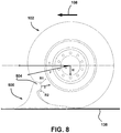
- FIG. 8 is a view similar to FIG. 7 but showing an example of the local deformation of the tire tread when a strong horizontal force T is applied and the smaller wheel chock of FIG. 7 is used;
- FIGS. 9 to 28 show examples of some of the anchoring arrangements that could be used between the wheel chock and the corresponding base plate;
- FIGS. 29 to 32 show another example of an anchoring arrangement but where the teeth of the base plate includes transversally-extending and spaced-apart rods supported by brackets;
- FIGS. 33 to 35 show examples of some of the features that can be used to help an operator in positioning the wheel chock on or off the base plate;
- FIGS. 36 to 43 show examples of base plates provided with a heating element therein that is capable of melting a layer of ice or snow in cold weather conditions;
- FIGS. 44 to 47 show another possible model of the wheel chock
- FIG. 48 is a semi-schematic side view illustrating an example of a conventional wheel chock at the time of initial contact with an example of a wheel of a vehicle;
- FIG. 49 is a view similar to FIG. 48 but showing the initial local deformation of the tire tread when a moderate horizontal force T is applied.
- FIG. 50 is a view similar to FIG. 48 but showing what happens when a strong horizontal force T is applied.
- FIG. 1 is a semi-schematic side view of an example of a wheel chock 100 in accordance with the proposed concept.
- the wheel chock 100 is in position immediately in front of a wheel 102 of a generic vehicle, in this case a truck trailer 104 . This is only one among a multitude of possible uses for the wheel chock 100 .
- the trailer 104 is designed to be hauled by a truck tractor and is schematically illustrated in FIG. 1 .
- the wheel chock 100 is part of a restraint system for preventing the trailer 104 from moving away in an unauthorized or accidental manner.
- the wheel chock 100 is designed to be positioned directly in front the wheel 102 over a ground-anchored serrated base plate 106 .
- the wheel chock 100 is in a tire-blocking position in FIG. 1 .
- the base plate 106 itself is rigidly anchored to the ground, for instance using bolts or any other suitable arrangement.
- the wheel chock 100 creates an obstacle that must be removed at the appropriate moment, for instance by the driver of the truck tractor, when the trailer 104 is ready and authorized to leave.
- the wheel chock 100 is otherwise left in position to block the wheel 102 , thereby blocking the whole trailer 104 .
- the wheel chock 100 can be connected to an articulated spring-assisted arm in some implementations. In others, it can simply be moved by hand, for instance with a handle or the like. Other arrangements and configurations are possible as well.
- the underside of the wheel chock 100 includes a plurality of teeth engaging corresponding teeth provided on the base plate 106 . They configured and disposed to hold the wheel chock 100 in a direction of departure 108 . At least one of the teeth under the wheel chock 100 must engage one tooth on the base plate 106 . There are also more teeth under the wheel chock 100 than the number of teeth on the base plate 106 for the same length. Nevertheless, the spacing between the teeth is designed so that the wheel chock 100 can fit at any position along the base plate 106 . This yield a greater flexibility in the adjustment of the positioning of the wheel chock 100 with reference to the wheel 102 . This is a desirable feature but it is possible to proceed differently in some implementations.
- the wheel chock 100 has an overall wheel chock height and an overall wheel chock length.
- the chock length is the horizontal dimension in the longitudinal direction, thus in a direction that is parallel to the departure direction 108 .
- the trailer 104 in the example of FIG. 1 is shown as being parked at a loading dock 110 and the back of the trailer 104 is close to a wall 112 located at the bottom end of the loading dock 110 . It can rest against a cushion or the like, as shown schematically in FIG. 1 .
- the wall 112 can be part of a commercial building, for instance a warehouse, a distribution center or the like. Variants are possible as well.
- the trailer 104 includes a cargo compartment 114 . Access into the cargo compartment 114 can be made for instance using a rear door on the trailer 104 , which rear door is positioned in registry with a corresponding door on the wall 112 .
- the floor of the cargo compartment 114 and the floor of the corresponding door are generally at the same height or at a similar height so that a lift truck or the like can load or unload the cargo therein.
- a ramp can be provided between both floors. Other variants are also possible.
- wheel chocks used for vehicles that are not truck trailers, including vehicles unrelated to the transport industry.
- loading docks are not the only locations where these wheel chocks can be provided.
- wheel chocks can be used with vehicles located in parking areas, truck stops, warehouses, distribution centers, etc.
- departure direction 108 in the figures may not always be the forward direction for all vehicles since some wheel chocks will need to be positioned behind a wheel instead of being positioned in front of it. Nevertheless, only for the sake of simplicity, the following detailed description will generally refer to the vehicle as being the trailer 104 at the loading dock 110 , which trailer 104 has a forward departure direction 108 .
- the wheel chock 100 is shown as being positioned between the wheel 102 and an adjacent wheel 116 located immediately in front of the wheel 102 .
- the wheel 102 and the adjacent wheel 116 are part of a tandem axle arrangement. Other kinds of arrangements and configurations are possible as well.
- the word “wheel” used in the context of the wheel chock 100 refers to the exterior wheel and/or the interior wheel. Most implementations will have the wheel chock 100 in position with only one of the wheels at a time, often the exterior wheel because of its proximity with the side of the vehicle. However, it may be possible to position the wheel chock 100 simultaneously in front of the two side-by-side wheels in some situations or even only in front of the interior wheel in others. It is thus intended that the word “wheel” in a singular form means either only one of the side-by-side wheels or both side-by-side wheels simultaneously in the context of a dual wheel arrangement.
- FIG. 2 is an enlarged semi-schematic side view of the wheel chock 100 shown in FIG. 1 and its corresponding wheel 102 at the time of their initial contact.
- the wheel 102 includes a rigid rim 130 and a tire 132 that is mounted around the rim 130 .
- the rim 130 is bolted or otherwise removably attached to a rotating element mounted to a corresponding axle of the trailer 104 .
- the tire 132 is made of an elastic material, for instance a material including rubber or the like.
- the illustrated tire 132 is a gas-inflated pneumatic tire filled with gas under pressure, for instance pressurized air. Pneumatic tires for truck trailers are often pressurized at about 100 psi. Variants are also possible.
- the tire 132 could be constructed without having a gas-inflated interior.
- the tire 132 includes two opposite sidewalls 134 , one being on the exterior side and the other on the interior side, and a circumferentially-disposed resilient tire tread 136 .
- the tire tread 136 is the main portion of the tire 132 engaging the ground surface 138 .
- the sidewalls 134 have a sidewall height, which can be defined as the radial distance between the outer edge of the rim 130 and the outer surface of the tire tread 136 .
- the radius of the wheel 102 namely the distance between the rotation axis 120 at the center of the wheel 102 and the outer surface of the tire tread 136 , is hereby referred to as the center height.
- FIG. 2 shows the wheel 102 not being on the base plate 106 but the wheel 102 can also be right over the base plate 106 in some circumstances.
- the circular shape of the tire tread 136 is normally disrupted at the bottom by a relatively flat contact area created between the tire tread 136 and the ground surface 138 .
- the dimensions of the wheel 102 can thus vary depending where the measurements are made when such load-induced tire deflection is present.
- the tire tread 136 is also subjected to wear and becomes progressively thinner over time.
- the sidewall height and the center height generally refer to the original dimensions of an unloaded wheel 102 . If the tire 132 is a gas-inflated tire, the pressure is assumed to be the adequate pressure in actual use.
- the sidewall height and the center height are considered to be substantially the same all around the wheel 102 when the wheel 102 is unloaded, for instance when the wheel 102 is detached from the trailer 104 and set horizontally on the ground surface 138 .
- the only significant force present is the local weight W caused by the mass of the load above the wheel axle and that is supported by the wheel 102 in front of which the wheel chock 100 is installed.
- the tire tread 136 is said to be in an undeformed state in FIG. 2 .
- the load-induced tire deflection at the bottom is not taken into account since it is a normal phenomenon.
- the tire tread 136 is in an undeformed state in FIG. 2 .
- the wheel chock 100 includes a main body 140 .
- the main body 140 is the supporting structure or frame capable of resisting the force applied on the wheel chock 100 by the wheel 102 .
- the main body 140 of the wheel chock 100 can have a monolithic construction and it can be entirely made of a rigid material, for instance a metal such as steel. Nevertheless, variants in the materials are possible as well.
- the expression “monolithic construction” means that there are no moving or easily detachable part once assembled and ready to be used. All parts of the main body 140 are rigidly connected together and it is not a foldable construction in normal operation. Otherwise, additional parts can be added to the main body 140 , if desired, but the basic functions of the main body 140 are not require any movable parts if it has a monolithic construction.
- the advantages of a monolithic construction include the simplicity of use and the increased resistance due to the absence of hinges or the like, particularly where the maximum stresses occur. Variants are possible as well.
- the main body 140 of the wheel chock 100 includes two spaced-apart main side members 142 .
- the side members 142 can be in the form of plates but variants are also possible. They can be rigidly connected together using transversal members, for instance a plurality of transversal members that are welded or otherwise rigidly connected to the interior faces of the side members 142 .
- the wheel chock 100 has a bottom base portion 144 where teeth 202 are located.
- the wheel chock 100 includes a tire-facing side 146 .
- the tire-facing side 146 is the side that is adjacent to the tire tread 136 when the wheel chock 100 is in position in front of the wheel 102 .
- the tire-facing side 146 of the wheel chock 100 is greatly recessed so as to create a tire deformation cavity 148 located immediately below a tire-engaging bulge 150 .
- the tire-engaging bulge 150 is located on the tire-facing side 146 .
- the tire deformation cavity 148 is shown by the hashed lines in FIG. 2 .
- the tire-engaging bulge 150 is located at a top end of the wheel chock 100 . It projects outwardly to create the part against which the tire tread 136 will exert most of its pressing force against the wheel chock 100 .
- the tire-engaging bulge 150 has a non-puncturing shape to prevent the tire tread 136 to be punctured or otherwise damaged.
- the tire-engaging bulge 150 can be in the form of a smooth and continuous rounded convex surface extending transversally. Variants are also possible. For instance, the tire-engaging bulge 150 can be more or less triangular in profile, with a rounded tip. Many other shapes are possible.
- the tire-engaging bulge 150 has a profile including a top surface portion and a bottom surface portion. The approximate medial line at the boundary between these top and bottom surface portions engages the tire tread 136 at what is referred to hereafter as the bulge engagement point 160 .
- the tire deformation cavity 148 defines a recessed tire-facing surface 152 that is spaced apart from the tire tread 136 when the tire tread 136 initially contacts the tire-engaging bulge 150 in an undeformed state.
- the recessed tire-facing surface 152 is provided by the parallel edges of the side members 142 . These two side members 142 are spaced apart from one another in this implementation. The space between the interior faces of the side members 142 can be left open, for instance to save weight, but the edges must then have a minimum width. The edges could otherwise act as blades and damage the tire tread 136 to prevent them from acting as blade edges that can puncture or otherwise rupture the tire tread 136 under an intense pressing force. If required, a ledge or a similar feature can be added to locally increase the width of each edge. Variants are possible as well.
- the hashed area in FIG. 2 represents the tire deformation cavity 148 , namely the volume available for a potential tire deformation when the wheel 102 is subjected to a horizontal force.
- the main purpose of the tire deformation cavity 148 is to capture as much volume as possible of the tire tread 136 on the bottom surface portion of the tire-engaging bulge 150 when the tire tread 136 is subjected to a deformation created by a horizontal force T.
- This horizontal force T can be the result, for instance, of a truck tractor pulling the trailer 104 in a departure direction 108 .
- the horizontal force T is applied at the rotation axis 120 of the wheel 102 .
- FIG. 3 is a view similar to FIG. 2 but showing an example of the local deformation 162 on the tire tread 136 caused by the wheel 102 being driven against the tire-engaging bulge 150 of the wheel chock 100 using a strong horizontal force T. Since the wheel chock 100 is attached to the base plate 106 , it will not move in the departure direction 108 when pushed by the wheel 102 due to the horizontal force T. As can be seen, the horizontal force T causes a disruption in the normal circular shape of the tire tread 136 . The tire tread 136 presses mostly against the tire-engaging bulge 150 of the wheel chock 100 . The tire 132 and its tire tread 136 are in a very deformed state in FIG. 3 . The deformed state started as soon as the horizontal force T created a sizeable disruption in the circular outer shape.
- FIG. 4 is an enlarged view of the top area identified in FIG. 3 .
- the tire tread 136 deforms around the tire-engaging bulge 150 and the pressure causes a local reaction force R from the tire tread 136 trying to recover its initial circular shape.
- two separate forces R 1 and R 2 are created around the tire-engaging bulge 150 since the tire tread 136 has space available both above and under the tire-engaging bulge 150 .
- some of the tire tread 136 now engages the recessed tire-facing surface 152 under the tire-engaging bulge 150 in the example depicted in FIG. 3 , most of the force opposing the horizontal force T is applied at the tire-engaging bulge 150 .
- the local reaction force R is shown in FIG. 3 only for the sake of illustration.
- the concept is that the upper surface portion and the bottom surface portion of the tire-engaging bulge 150 cause the local reaction force R to be substantially horizontal or very close to it.
- the local reaction force R essentially works against the horizontal force T, thus increasing angle “a” of the resulting force vector and helping the wheel 102 to be kept in place over the wheel chock 100 since the path of the resulting force vector F will remain below the top of the wheel chock 100 .
- the tire-engaging bulge 150 should be as close as possible to the rotation axis 120 of the wheel 102 . Placing it above it could even lower or eliminate the upward lifting force component that can potentially lift the wheel 102 above the ground surface 138 . However, height and/or weight restrictions often make this impossible and in many implementations, the tire-engaging bulge 150 will engage the tire tread 136 vertically below the rotation axis 120 .
- the weight W of the trailer 104 is also a factor that helps keeping the wheel 102 on the ground surface 138 .
- a heavier trailer 104 will be more difficult to lift.
- an empty trailer 104 , or a trailer 104 with a light-weight cargo is more difficult to retain using a conventional wheel chock.
- the wheel chock 100 When designing the wheel chock 100 , a proper balance must be found between various parameters such as the size limitations (for instance the available space between adjacent wheels, the presence of obstacles, etc.), the maximum chock weight beyond which the wheel chock 100 will be considered too heavy to be handled by most operators, the material strength, the wheel diameter, the tire pressure, and the various forces involved, such as the minimum local weight W and the maximum horizontal force T exerted by or on the wheel 102 . Truck tractors with large engines can generate a very considerable torque and the horizontal force T can be significant when the traction conditions are optimal.
- the size limitations for instance the available space between adjacent wheels, the presence of obstacles, etc.
- the maximum chock weight beyond which the wheel chock 100 will be considered too heavy to be handled by most operators the material strength, the wheel diameter, the tire pressure, and the various forces involved, such as the minimum local weight W and the maximum horizontal force T exerted by or on the wheel 102 .
- Truck tractors with large engines can generate a very considerable torque and the horizontal force T can be
- the tire tread 136 also has a maximum stress limit that it can withstand prior to a tire failure, for instance a blowout due to at least one of the inner sides of the tire 132 detaching at some point from the outer perimeter of the rim 130 .
- a maximum horizontal force T developed by most vehicles.
- the design of the wheel chock 100 can then use the maximum stress of a tire, possibly with a safety factor, as the maximum horizontal force T beyond which the wheel 102 could, in theory, roll over the wheel chock 100 when proper traction conditions are present.
- These design parameters would be based on the assumption that either the horizontal force T cannot be high enough to overcome the wheel chock 100 or either that the tire 132 will fail if the horizontal force T does reach that magnitude.
- exceptions exist most thieves may not be tempted by the prospect of having to drive or haul a vehicle such as the trailer with a damaged tire because this situation can attract attention and it can also significantly impair the vehicle's drivability.
- the tire deformation cavity 148 preferably has a depth that is at least about 30% of the sidewall height at a deepest location of the tire deformation cavity 148 . This was found to be adequate for many implementations. Variants are possible as well. This depth is measured when the tire tread 136 engages the tire-engaging bulge 150 in an undeformed state, as in FIG. 2 . The distance is taken from the outer surface of the tire tread 136 to the recessed tire-facing surface 152 .
- the bottom surface portion of the tire-engaging bulge 150 merge with the top edge of the recessed tire-facing surface 152 and the tire-engaging bulge 150 projects outwards beyond the projection of the recessed tire-facing surface 152 , which projection in depicted with stippled lines.
- the recessed tire-facing surface 152 has a curved shape, at least in its upper half, where it is curved with a minimum radius that is at least half of the wheel diameter. This helps in providing the space for the tire-engaging bulge 150 to go deep within the tire tread 136 when subjected to a very intense force.
- the wheel chock 100 can include a bottom tire-engaging point 164 over which the bottom part of the tire tread 136 can be positioned when the tire tread 136 forcefully engages the tire-engaging bulge 150 .
- the bottom tire-engaging point 164 is located below the tire deformation cavity 148 . While it is still possible to design the wheel chock 100 differently, it is generally desirable that the tire tread 136 engages the bottom tire-engaging point 164 only after the tire tread 136 made the initial contact with the tire-engaging bulge 150 . This can mitigate or even alleviate the risks of the wheel chock 100 being wedged under the wheel 102 , for instance due to a significant increase of the weight W.
- the progressive deformation of the tire 132 due to the added weight can trap (or wedge) the wheel chock 100 and prevent it from being easily removed when needed. Nevertheless, the weight W can be useful to force the wheel chock 100 into engagement with a base plate 106 covered by a layer of snow, ice or even dirt.
- the bottom tire-engaging point 164 can also be set at a minimal height from the ground surface 138 and this can also help in preventing the wheel chock 100 from being stuck.
- FIG. 5 is an enlarged view of the bottom area in FIG. 3 . It shows that a local reaction force (R 3 ) is also produced at the interface between a tooth 202 of the wheel chock 100 and the corresponding tooth 204 of the base plate 106 .
- the chock tooth 202 and the base plate tooth 204 in this example have mating surfaces positioned at an equal angle (b) from the horizontal. The larger this angle (b) is, the more horizontal the local reaction force (R 3 ) will be, and thus, the local reaction force R at the tire-engaging bulge 150 will eventually lead to the wheel chock 100 coming off the base plate 106 , forcing the wheel chock 100 to pivot about its front lower edge.
- FIG. 6 is a semi-schematic side view of the wheel 102 alone.
- FIG. 6 schematically depicts an upper portion 170 of the lower leading quadrant 172 of the wheel 102 .
- the lower leading quadrant 172 is the region on the tire tread 136 that is towards the departure direction 108 and between the horizontal centerline 174 of the wheel 102 and the vertical centerline 176 of the wheel 102 .
- the upper portion 170 is where the bulge engagement point 160 will be located. Having the bulge engagement point 160 as close as possible to the horizontal wheel centerline 174 increases efficiency. Nevertheless, excellent performance results can still be obtained if the budge engagement point 160 will be lower within the upper portion 170 of the lower leading quadrant 172 .
- the upper portion 170 should have a lower boundary that is located at a vertical distance 178 under the horizontal wheel centerline 174 of about 15% of the wheel diameter.
- FIG. 7 is a semi-schematic side view of an example of a wheel chock 500 , at the time of initial contact.
- This wheel chock 500 is relatively too small in height with reference to the size of the wheel 102 . In other words, the wheel chock 500 does not have the proper size.
- the shape of the wheel chock 500 is otherwise substantially similar to that of the wheel chock 100 of FIG. 1 .
- the wheel chock 500 has a tire deformation zone 502 .
- FIG. 8 is a view similar to FIG. 7 but showing an example of the local deformation on the tire tread 136 when a strong horizontal force T is applied and the smaller wheel chock 500 of FIG. 7 is used.
- FIG. 8 depicts the limitations in chock height.
- the local reaction force R is more upward acting because of an imbalance between tire deformation above and below the tire-engaging bulge 504 (R 2 being smaller than R 1 ).
- the local reaction force R has a smaller impact on the resulting force vector F and the angle “a”, and in this case, the horizontal force T will more easily cause wheel to overcome the wheel chock height, particularly if the weight W is relatively small.
- FIGS. 9 to 28 show examples of some of the anchoring arrangements that can be used between the wheel chock 100 and the corresponding base plate 106 .
- FIGS. 9 to 16 are two examples of existing anchoring arrangements having teeth 202 on the wheel chock 100 and teeth 204 on the base plate 106 .
- the teeth 204 can be welded or otherwise rigidly attached to the upper surface of the base plate 106 .
- FIGS. 17 to 20 show an example of a novel anchoring arrangement where the teeth 202 , 204 create a positive latched engagement when the wheel chock 100 is in position since both share a common horizontally-extending surface.
- FIG. 17 only illustrates one of the side members 142 of the wheel chock 100 .
- FIG. 18 is an enlarged view of an area shown in FIG. 17 .
- FIG. 19 is a side view of the base plate 106 and the side member 142 shown in FIG. 17 .
- FIG. 20 is an enlarged view of an area identified in FIG. 19 .
- the teeth 204 of the base plate 106 have an inverted L-shaped cross section and the side member 142 also have teeth 204 with a L-shaped cross section, one side however being sloped.
- the teeth 202 and the teeth 204 meet on the side opposite to the departure direction 108 .
- This arrangement helps mitigating the risks of the teeth 202 , 204 being disconnected if the wheel 102 does have an upward lifting motion, for instance after repeated attempts by the driver to pull the trailer 104 with force.
- the magnitude and the direction of the forces exerted by the tire tread 136 on the top end of the wheel chock 100 could potentially cause the teeth 202 from detaching from the teeth 204 of the base plate 106 .
- the illustrated arrangement helps prevent the wheel chock 100 from tipping, especially in a situation where a major pulling force is utilized to move the trailer 104 and the trailer 104 is empty or only lightly loaded.
- FIGS. 21 to 28 show two other examples of novel anchoring arrangements including teeth 202 and corresponding teeth 204 . These anchoring arrangements also feature a horizontally-extending surface.
- FIGS. 29 to 32 show another example of an anchoring arrangement but where the teeth 204 of the base plate 106 include transversally-extending and spaced-apart rods supported by brackets 206 .
- Each tooth 204 is supported above the upper surface of the base plate 106 by a plurality of brackets 206 .
- the teeth 202 underneath the wheel chock 100 will engage some of the teeth 204 .
- the teeth 202 of this wheel chock 100 are slanted and include sharp tips. The sharp tips can be useful in cold weather conditions if the base plate 106 has some ice or snow thereon.
- FIG. 30 shows only the base plate 106 .
- the teeth 202 are designed to fit under the bottom of the teeth 204 when the wheel chock 100 is in a tire-blocking position. This will increase the resistance against an upward motion since the teeth 202 engage a large proportion of the circumference of the teeth 204 .
- FIGS. 33 to 35 show examples of some of the features that can be used to help an operator in positioning the wheel chock 100 on or off the base plate 106 .
- FIG. 33 shows an example of an articulated spring-assisted arm 180 having a proximal end attached to the wall 112 by means of a first swivel device 182 and a distal end attached on the side of the main body 140 of the wheel chock 100 by a second swivel device 184 .
- the arm 180 includes a proximal arm member 186 and a distal arm member 188 . Both are pivotally connected together in juxtaposition using a hinge 190 .
- a weight-supporting spring 192 extends between the first swivel device 182 and the proximal arm member 186 to counterbalance at least part of the total weight of the restrain system.
- the spring 192 can also be attached directly to the wall 112 .
- the spring 192 is attached to the proximal arm member 186 using a tension adjustment device 194 .
- This device 194 includes for instance a nut and screw arrangement to modify the tension of the spring 192 . This can thus vary the tension, for instance to increase or decrease the counterbalancing force from the spring 192 . Variants are possible as well.
- FIG. 34 shows an example of the wheel chock 100 with a handle 196 mounted on top thereof.
- the handle 196 of this illustrated example is flexible in order not to interfere with tire deformation. Variants are possible as well.
- FIG. 35 shows an example of a wheeled cart 198 attached to the wheel chock 100 .
- FIGS. 36 to 43 show examples of base plates 106 provided with a heating element therein that is capable of melting ice and snow in cold weather conditions.
- FIG. 36 is an upper isometric view of an example of a base plate 106 having a heating element 300 located under an upper plate.
- This heating element 300 can be for instance a self-regulating heating electrical cable.
- FIG. 37 is a bottom isometric view of the base plate 106 of FIG. 36 .
- FIG. 38 is an upper isometric view of the base plate of FIG. 36 but with a first portion of the upper plate 302 being removed for the sake of illustration.
- FIG. 39 is also an upper isometric view of the base plate 106 of FIG. 36 but with a second portion of the upper plate 302 being removed to show another portion of the heating element 300 therein.
- This heating element 300 is in the form of a heating cable that runs through a U-shaped section of pipe. Heat is transferred to ground plate through a series of plates attached directly to underside of the base plate 106 . This structure can also be buried in the ground under the base plate 106 to prevent any additional vertical height increase. Variants are possible as well.
- FIG. 40 is an upper isometric view of another example of a base plate 106 having a heating element 300 located under an upper plate.
- This heating element 300 can also be for instance a self-regulating heating electrical cable.
- FIG. 41 is a bottom isometric view of the base plate 106 of FIG. 40 .
- the heating cable 300 runs between two steel plates with an internal structure to permit a back and forth path for the cable 300 . Heat is transferred through a top steel plate which is connected directly to underside of the base plate 106 .
- FIG. 42 is an upper isometric view of the base plate 106 of FIG. 40 but with a first portion of the upper plate being removed to show the heating element 300 therein.
- FIG. 43 is a also an upper isometric view of the base plate 106 of FIG. 36 but with a second portion of the upper plate being removed to show another portion of the heating element therein.
- FIGS. 44 to 47 show another possible model of a wheel chock 800 .
- This wheel chock 800 includes an upper frame member 802 , made of tubing or the like, and that is rigidly connected to a rigid bottom frame member 804 .
- the underside of the bottom frame member 804 includes teeth 806 and the wheel chock 800 is designed to be set on a base plate, for instance the base plate 106 from the previous figures. Variants are possible as well.
- the upper frame member 802 of the wheel chock 800 has two transversal members 808 , 810 . They are rigidly attached to the side portion of the upper frame member 802 , which side portion has a shape that is somewhat similar to an inverted “Y”.
- the tire deformation zone is formed between the two transversal members 808 , 810 .
- the top transversal member 810 of the illustrated example is only attached at one end and the opposite end is a free end.
- the upper frame member 802 has one side that is completely opened.
- FIGS. 48 to 50 were discussed in the background section. They are semi-schematic side views illustrating an example of a conventional wheel chock 900 .
- Tests were conducted on a test bench for comparison between an existing wheel chock model, similar to that of FIGS. 48 to 50 , of 20 inches (50.8 cm) in height and a wheel chock similar for instance to the wheel chock 100 in FIGS. 1 and 3 , of 20 inches (50.8 cm).
- the wheel was a gas-inflated tire of 42 inches (122 cm) in diameter and the local weight W was set to 2,300 lbs. (1043 kg) in both cases to simulate a lightly loaded trailer. It was measured that with the conventional wheel chock, a roll over occurred with a horizontal force T of about 11,400 lbs. (5170 kg). However, no rollover occurred with the newly-designed wheel chock for the same horizontal force T. The horizontal force T was increased up to 20,600 lbs. (9344 kg) and still, no rollover occurred. The tire showed signs of an imminent failure and the horizontal force T was not further increased for that reason. It was clear that the rollover was not an issue and that the tire itself was the weak point.
- wheel chocks designed and constructed as disclosed herein will perform better than conventional wheel chocks of the same size.
Landscapes
- Engineering & Computer Science (AREA)
- Mechanical Engineering (AREA)
- Transportation (AREA)
- Health & Medical Sciences (AREA)
- Public Health (AREA)
- Aviation & Aerospace Engineering (AREA)
- Tires In General (AREA)
Abstract
Description
- 100 wheel chock
- 102 wheel
- 104 trailer
- 106 base plate
- 108 departure direction
- 110 loading dock
- 112 wall
- 114 cargo compartment
- 116 adjacent wheel
- 120 rotation axis
- 130 rim
- 132 tire
- 134 sidewall
- 136 tire tread
- 138 ground surface
- 140 main body
- 142 side member
- 144 bottom base portion
- 146 tire facing side
- 148 tire deformation cavity
- 150 tire-engaging bulge
- 152 recessed tire-facing surface
- 160 bulge engagement point
- 162 local deformation
- 164 bottom tire-engaging point
- 170 upper portion
- 172 lower leading quadrant
- 174 horizontal wheel centerline
- 176 vertical wheel centerline
- 178 vertical distance
- 180 articulated spring-assisted arm
- 182 first swivel device
- 184 second swivel device
- 186 proximal arm member
- 188 distal arm member
- 190 hinge
- 192 spring
- 194 tension adjustment device
- 196 handle
- 198 wheeled cart
- 202 tooth (wheel chock)
- 204 tooth (base plate)
- 206 bracket
- 210 common horizontally-extending surface
- 500 wheel chock
- 502 tire deformation cavity
- 504 tire-engaging bulge
- 800 wheel chock
- 802 upper frame member
- 804 bottom frame member
- 806 tooth
- 808 bottom transversal member
- 810 top transversal member
- 900 conventional wheel chock
- 902 wheel
- 904 rim
- 906 tire
- 908 ground surface
- 910 contact surface
- 912 upper edge
- 914 tire tread
Claims (20)
Priority Applications (4)
Application Number | Priority Date | Filing Date | Title |
---|---|---|---|
US15/167,497 US10864895B2 (en) | 2013-11-29 | 2016-05-27 | Wheel chock and method |
US17/120,777 US11479217B2 (en) | 2013-11-29 | 2020-12-14 | Wheel chock and method |
US17/971,306 US11987223B2 (en) | 2013-11-29 | 2022-10-21 | Wheel chock and method |
US18/440,430 US20240182002A1 (en) | 2013-11-29 | 2024-02-13 | Wheel Chock and Method |
Applications Claiming Priority (3)
Application Number | Priority Date | Filing Date | Title |
---|---|---|---|
US201361910264P | 2013-11-29 | 2013-11-29 | |
PCT/CA2014/051143 WO2015077893A1 (en) | 2013-11-29 | 2014-11-28 | Wheel chock and method |
US15/167,497 US10864895B2 (en) | 2013-11-29 | 2016-05-27 | Wheel chock and method |
Related Parent Applications (1)
Application Number | Title | Priority Date | Filing Date |
---|---|---|---|
PCT/CA2014/051143 Continuation WO2015077893A1 (en) | 2013-11-29 | 2014-11-28 | Wheel chock and method |
Related Child Applications (1)
Application Number | Title | Priority Date | Filing Date |
---|---|---|---|
US17/120,777 Continuation US11479217B2 (en) | 2013-11-29 | 2020-12-14 | Wheel chock and method |
Publications (2)
Publication Number | Publication Date |
---|---|
US20160272168A1 US20160272168A1 (en) | 2016-09-22 |
US10864895B2 true US10864895B2 (en) | 2020-12-15 |
Family
ID=53191434
Family Applications (4)
Application Number | Title | Priority Date | Filing Date |
---|---|---|---|
US15/167,497 Active 2035-10-20 US10864895B2 (en) | 2013-11-29 | 2016-05-27 | Wheel chock and method |
US17/120,777 Active US11479217B2 (en) | 2013-11-29 | 2020-12-14 | Wheel chock and method |
US17/971,306 Active US11987223B2 (en) | 2013-11-29 | 2022-10-21 | Wheel chock and method |
US18/440,430 Pending US20240182002A1 (en) | 2013-11-29 | 2024-02-13 | Wheel Chock and Method |
Family Applications After (3)
Application Number | Title | Priority Date | Filing Date |
---|---|---|---|
US17/120,777 Active US11479217B2 (en) | 2013-11-29 | 2020-12-14 | Wheel chock and method |
US17/971,306 Active US11987223B2 (en) | 2013-11-29 | 2022-10-21 | Wheel chock and method |
US18/440,430 Pending US20240182002A1 (en) | 2013-11-29 | 2024-02-13 | Wheel Chock and Method |
Country Status (6)
Country | Link |
---|---|
US (4) | US10864895B2 (en) |
EP (1) | EP3074282B1 (en) |
CA (1) | CA2931849C (en) |
ES (1) | ES2642835T3 (en) |
PL (1) | PL3074282T3 (en) |
WO (1) | WO2015077893A1 (en) |
Cited By (7)
Publication number | Priority date | Publication date | Assignee | Title |
---|---|---|---|---|
US11319173B2 (en) * | 2017-11-07 | 2022-05-03 | Jvj Maskinteknik Aps | System for preventing semitrailer collisions with a loading ramp |
US11479217B2 (en) * | 2013-11-29 | 2022-10-25 | 9172-9863 Quebec Inc. | Wheel chock and method |
USD987542S1 (en) * | 2021-03-22 | 2023-05-30 | 9172-9863 Québec Inc. | Wheel chock |
USD995394S1 (en) * | 2021-03-22 | 2023-08-15 | 9172-9863 Québec Inc. | Wheel chock |
EP4253172A1 (en) | 2022-03-31 | 2023-10-04 | 9172-9863 Québec Inc. | Wheel chock with a longitudinal extension |
US12005874B2 (en) | 2017-09-14 | 2024-06-11 | 9172-9863 Quebec Inc. | Wheel chock with locking mechanism |
USD1042293S1 (en) | 2023-06-01 | 2024-09-17 | 9172-9863 Québec Inc. | Chock to prevent vehicles from moving |
Families Citing this family (8)
Publication number | Priority date | Publication date | Assignee | Title |
---|---|---|---|---|
PL3303073T3 (en) * | 2015-06-03 | 2020-04-30 | 9172-9863 Québec Inc. | Bidirectional wheel chock restraint system |
US10329104B2 (en) | 2016-04-04 | 2019-06-25 | Assa Abloy Entrance Systems Ab | Vehicle restraint |
US9751702B1 (en) | 2016-06-06 | 2017-09-05 | ASSA ABLOY Entrance Systems, Inc. | Wheel chock systems |
ES2961336T3 (en) * | 2018-11-09 | 2024-03-11 | 9172 9863 Quebec Inc | Wheel Chock Handling Unit |
USD949746S1 (en) * | 2018-11-15 | 2022-04-26 | Etn Capital Llc | RV leveler |
US10988329B2 (en) | 2019-02-15 | 2021-04-27 | Assa Abloy Entrance Systems Ab | Vehicle restraint |
US11618642B2 (en) | 2020-08-20 | 2023-04-04 | Assa Abloy Entrance Systems Ab | Vehicle restraint systems and methods |
CN112158177B (en) * | 2020-09-24 | 2021-11-30 | 湖南汽车工程职业学院 | Assistor for automobile hill starting |
Citations (177)
Publication number | Priority date | Publication date | Assignee | Title |
---|---|---|---|---|
DE609179C (en) | 1933-03-16 | 1935-02-09 | Fritz Schleifenbaum Dr | Device for determining load on the floor of transport vehicles |
DE633272C (en) | 1933-09-08 | 1936-07-23 | Jean Krug Basse | Foldable ramp |
US2316178A (en) | 1941-03-03 | 1943-04-13 | Jr Otto Morgensen | Airplane wheel chock |
US2413744A (en) | 1945-07-09 | 1947-01-07 | Carter Clarence | Mechanical floor chock |
US2771162A (en) | 1952-04-14 | 1956-11-20 | Eastern Rotorcraft Corp | Adjustable wheel chock |
GB774550A (en) | 1954-09-14 | 1957-05-08 | Hugh Quentin Alleyne Reeves | Improvements in silencing equipment for the engine testing of jet-engined aircraft when stationary on the ground |
GB779681A (en) | 1955-02-08 | 1957-07-24 | Sylvia Reeves | Wheel-holding chocks for aircraft |
US2858905A (en) | 1956-06-29 | 1958-11-04 | Fahland Frank | Adjustable wheel block |
US2954101A (en) | 1959-01-19 | 1960-09-27 | William E Corson | Vehicle wheel chock |
US3065827A (en) * | 1960-08-22 | 1962-11-27 | Lawrence J Timbers | Wheel chock |
US3074569A (en) | 1959-01-28 | 1963-01-22 | Albert I Kegan | Side-load and unload structure for railway-carried highway trailers |
US3077247A (en) | 1961-01-31 | 1963-02-12 | Coast Engineer & Supply Co | Stationary airplane wheel chock |
US3119466A (en) | 1960-10-24 | 1964-01-28 | Norman F Gilson | Wheel blocking device |
US3120292A (en) | 1962-03-22 | 1964-02-04 | Harry F Rambat | Vehicle wheel chock |
US3157194A (en) | 1962-09-21 | 1964-11-17 | Gas Tools Inc | Interlock mechanism |
US3189127A (en) | 1963-07-30 | 1965-06-15 | Karnow Paul | Universal wheel chock |
US3258088A (en) | 1963-05-27 | 1966-06-28 | William D Bowen | Spring action wheel chock |
US3321046A (en) | 1966-05-02 | 1967-05-23 | Arley E Cooper | Wheel blocking system |
US3425517A (en) | 1967-11-22 | 1969-02-04 | Charles D Speir | Automatic wheel chock |
US3542157A (en) | 1969-02-13 | 1970-11-24 | Frederick G Noah | Automatic dock wheel chock for trailers |
US3581846A (en) | 1969-07-14 | 1971-06-01 | Julian A Janus | Safety locking block device for wheeled vehicles |
US3666119A (en) | 1970-09-25 | 1972-05-30 | Ward H Parsons | Automatic loading and signaling system for driver operated vehicles |
US3695394A (en) | 1970-10-08 | 1972-10-03 | Walter C Carpenter | Locking wheel chocks for tandem wheel vehicles |
US3700077A (en) | 1971-07-13 | 1972-10-24 | Abraham Harder | Chock for a tandem wheeled trailer |
US3734241A (en) | 1971-08-30 | 1973-05-22 | C Hale | Drive on no slip block |
US3845844A (en) | 1973-03-19 | 1974-11-05 | J Woerner | Wheel chocks for tandem wheels |
US3907072A (en) | 1974-08-22 | 1975-09-23 | Lawrence Peska Ass Inc | Chock-lock block |
US4155523A (en) | 1977-03-23 | 1979-05-22 | Dave Heerboth | Aircraft landing gear assembly |
US4155429A (en) | 1978-02-06 | 1979-05-22 | Schessl Ronald G | Adjustable wheel chock assembly |
US4191503A (en) | 1978-02-01 | 1980-03-04 | Rite-Hite Corporation | Device for releasably securing one unit against a second unit |
US4207019A (en) | 1978-09-11 | 1980-06-10 | Cone Malcolm S | Truck dock wheel safety chock system |
US4441586A (en) | 1981-10-19 | 1984-04-10 | Bernier Jean P | Device for immobilizing a wheeled vehicle |
EP0128992A1 (en) | 1983-06-21 | 1984-12-27 | Lohr S.A. | Concealable block for securing vehicles on a lorry |
US4555211A (en) | 1982-06-11 | 1985-11-26 | Metz Donald L | Truck locking device |
US4582176A (en) | 1984-07-23 | 1986-04-15 | Burlington Industries, Inc. | Lockable chock for dual wheels of vehicle |
US4676344A (en) | 1983-06-13 | 1987-06-30 | Locicero Frank J | Self-locking chocks for a semi-trailer |
US4682922A (en) | 1984-11-19 | 1987-07-28 | Lohr S.A. | Vehicle wheel support and fastening device |
US4739863A (en) | 1986-07-11 | 1988-04-26 | Stauffer Richard L | Vat wheel lock |
US4781271A (en) * | 1986-07-15 | 1988-11-01 | Arthur Wokeck | Wheel chock blocks |
US4784567A (en) | 1985-11-20 | 1988-11-15 | Kelley Company Inc. | Vehicle restraint utilizing a fluid cylinder |
US4804070A (en) | 1988-07-29 | 1989-02-14 | Bohler Gerard M | Lockable vehicle wheel chock device |
US4833442A (en) | 1987-06-19 | 1989-05-23 | Robert Von Heck | Wheel immobilizer-chock w/integral latch and alarm |
US4854790A (en) | 1987-01-16 | 1989-08-08 | Lohr Industrie | Vehicle wheel support and fastening device |
US4934489A (en) | 1989-03-15 | 1990-06-19 | Jackson Carl E | Tandem tire brake |
US4955459A (en) | 1989-02-28 | 1990-09-11 | Consolidated Rail Corporation | Strapless wheel chocking assembly |
US4963068A (en) | 1989-01-23 | 1990-10-16 | Systems, Inc. | Trailer restraint |
US4969792A (en) | 1988-09-01 | 1990-11-13 | Kelley Company Inc. | Truck supporting device |
US4973213A (en) | 1989-09-21 | 1990-11-27 | Kelley Company Inc. | Truck actuated vehicle restraint having a pivotable inclined surface |
FR2652340B1 (en) | 1989-09-28 | 1992-01-10 | Chateauneuf La Foret Papeterie | DEVICE FOR SETTING UP A FOLDING HOLDER IN PARTICULAR IN FRONT OF AT LEAST ONE WHEEL OF A TRUCK. |
US5096021A (en) | 1991-05-08 | 1992-03-17 | Charles Tart | Tire chock interlock system for a gas truck |
US5173018A (en) | 1991-03-12 | 1992-12-22 | Kissel James L | Security system for wheeled vehicles residing on a moving deck |
US5249905A (en) | 1992-07-22 | 1993-10-05 | Kelley Company, Inc. | Automatic wheel chocking apparatus having an improved drive mechanism |
US5286138A (en) | 1989-12-08 | 1994-02-15 | Cedarapids, Inc. | Vehicle positioning methods and apparatus with impact damper |
US5302063A (en) | 1992-02-28 | 1994-04-12 | Holden America Inc. | Vehicle wheel chock |
US5348437A (en) | 1993-05-17 | 1994-09-20 | Overhead Door Corporation | Vehicle restraining apparatus |
EP0384850B1 (en) | 1989-02-24 | 1994-11-02 | Gilles Glomot | Automatic stopping device for a vehicle in particular for a truck in front of a loading bay |
US5368134A (en) | 1993-10-20 | 1994-11-29 | Rickman; Harold | Tandem wheel block apparatus |
US5375965A (en) | 1993-01-25 | 1994-12-27 | Rite-Hite Corporation | Vehicle restraining device |
US5381680A (en) | 1993-09-23 | 1995-01-17 | Rauch, Jr.; Joseph J. | Retractable wheel lock assembly |
US5392880A (en) | 1994-01-25 | 1995-02-28 | Christian; Melvin L. | Tire clock for tandem wheels |
EP0537075B1 (en) | 1991-10-09 | 1995-04-26 | Michel Roux | Plant for immobilizing a transport vehicle in a predetermined loading position |
US5410897A (en) | 1993-07-13 | 1995-05-02 | Edmondson; Jack M. | Vehicle wheel locking and anti-theft device |
US5427209A (en) | 1994-03-14 | 1995-06-27 | Tannehill; William B. | Vehicle washing aid |
US5435418A (en) | 1994-08-11 | 1995-07-25 | Transtech Resources, Inc. | Emergency brake system for wheeled vehicles |
US5531557A (en) | 1994-07-01 | 1996-07-02 | Rite-Hite Corporation | Drive screw system with nested mobile supports |
US5547045A (en) | 1995-04-11 | 1996-08-20 | Stutzman; Jay | Adjustable wheel chocks for tandem wheeled vehicles |
US5553987A (en) | 1994-03-07 | 1996-09-10 | Rite-Hite Corporation | Truck activated wheel chocking device |
EP0496727B1 (en) | 1988-04-14 | 1996-09-18 | ROSSMANN, Viktor | Safety wheel-chock for vehicles |
EP0744327A1 (en) * | 1995-05-19 | 1996-11-27 | Officina Meccanica Migliore Livio | Car blocking chock |
US5582498A (en) | 1994-10-21 | 1996-12-10 | Rite-Hite Corporation | Wheel activated vehicle restraint |
US5683219A (en) | 1996-06-07 | 1997-11-04 | Pioneer Manufacturing, Inc. | Mechanical truck restraint |
WO1997049625A1 (en) | 1996-06-21 | 1997-12-31 | Van Wijk Nederland B.V. | Restraining device for the wheels of a motor vehicle |
GB2290590B (en) | 1994-06-27 | 1998-04-22 | Trevor Paul Bickerton | A device for preventing or hindering rolling movement of a vehicle wheel |
US5743697A (en) | 1994-11-29 | 1998-04-28 | United Dominion Ind., Inc. | Automatic wheel chock |
US5762459A (en) | 1994-10-21 | 1998-06-09 | Rite-Hite Corporation | Wheel-activated vehicle restraint system |
US5790518A (en) | 1995-12-22 | 1998-08-04 | Hughes Electronics Corporation | 1-for-N redundancy implementation on midplane |
US5803208A (en) | 1996-02-01 | 1998-09-08 | Tripus Gmbh Kunststoff- Und Elektrotechnik | Safety accessory for vehicles |
EP0836579B1 (en) | 1995-07-04 | 1999-02-24 | Michel Roux | Apparatus for immobilising a utility vehicle relative to a transshipment facility |
US5878940A (en) | 1996-01-16 | 1999-03-09 | Deere & Company | Method of fabricating sheet metal structures by welding and structure formed thereby |
US5902082A (en) | 1996-03-27 | 1999-05-11 | Spanset Inter Ag | Tie-down device |
US5901816A (en) | 1998-02-19 | 1999-05-11 | Camilleri; Tony C. | Air cylinder-driven wheel chock |
US5934857A (en) | 1996-11-21 | 1999-08-10 | United Dominion Ind., Inc | Automatic wheel chock system |
US6082952A (en) | 1997-12-12 | 2000-07-04 | United Dominion Ind., Inc. | Automatic wheel chock system |
US6092970A (en) * | 1998-01-09 | 2000-07-25 | Rite-Hite Holding Corporation | Manually positioned wheel chocking apparatus |
EP1095880A1 (en) | 1999-10-25 | 2001-05-02 | Kelley Company, Inc. | Powered wheel chocking device |
US6290029B1 (en) | 2000-12-26 | 2001-09-18 | Tyler Wilson Gubler | Compact adjustable wheel chock assembly for retainment of multi-size wheels |
US20010026751A1 (en) | 2000-01-28 | 2001-10-04 | Jan Berends | Device for blocking a vehicle |
US6336527B1 (en) | 2001-01-05 | 2002-01-08 | Donald Metz | Wheel chock with handle and tire sensing device |
US6357987B1 (en) | 1999-12-29 | 2002-03-19 | Kelley Company, Inc. | Powered wheel chock with folding supports |
US6371253B1 (en) | 1993-12-28 | 2002-04-16 | Stertil B. V. | Wheel blocking device |
US6378956B1 (en) | 1999-04-22 | 2002-04-30 | Larry G. Van De Walker | Wheel chock assembly |
US6425465B1 (en) | 1999-09-14 | 2002-07-30 | Norco Industries, Inc. | Locking wheel chock apparatus for single tire |
US6439823B1 (en) | 2000-10-26 | 2002-08-27 | Pro-Qual Inc. | Vehicle restraint device |
US6505713B1 (en) | 2000-08-24 | 2003-01-14 | Rite-Hite Holding Corporation | Tire locating wheel restraint |
US20030099528A1 (en) | 1999-06-17 | 2003-05-29 | Hageman Martin P. | Wheel chocking device and method for using the same |
US6585211B1 (en) | 1996-06-27 | 2003-07-01 | Kelley Company, Inc. | Wheel chocking device and method for using the same |
US6589003B2 (en) | 1999-12-03 | 2003-07-08 | Stertil B.V. | Vehicle blocking device |
EP1167253B1 (en) | 2000-06-23 | 2004-04-14 | Stertil B.V. | Device for stopping trucks |
US6725979B1 (en) | 2002-07-05 | 2004-04-27 | Kenneth G. Snook | Tire stop lock |
US20040108172A1 (en) | 2002-12-04 | 2004-06-10 | Norco Industries, Inc. | Wheel locking chock |
US6752381B2 (en) | 2002-02-06 | 2004-06-22 | Tri-Lynx Corporation | Wheel positional restraint device and method for using the same |
US6773221B2 (en) | 2001-07-05 | 2004-08-10 | Rite-Hite Holding Corporation | Positive locking mechanism for a wheel-activated vehicle restraint |
US6835034B2 (en) | 2003-01-02 | 2004-12-28 | Robert Winsor | Method and system for restraining road vehicle on a transport vehicle |
US6851523B1 (en) | 2003-10-06 | 2005-02-08 | Ivan Gaster | Shock absorbing vehicle wheel chock |
US20050047887A1 (en) | 2003-08-25 | 2005-03-03 | Mark Kenny | Vehicle restraint system |
US6863481B2 (en) | 2003-07-21 | 2005-03-08 | Pingel Enterprise, Inc. | Wheel chock mounting plate assembly |
US20050133315A1 (en) | 2003-12-23 | 2005-06-23 | Hoofard Richard K. | Vehicle restraint system and method |
US6938734B2 (en) | 2003-03-26 | 2005-09-06 | Richard Curl | Universal wheel locking system |
US6948593B2 (en) | 2003-08-13 | 2005-09-27 | Horton Steven K | Wheel chock |
US6978865B2 (en) | 2001-02-02 | 2005-12-27 | Safety Chock Systems International Incorporated | Safety chock |
FR2873351A1 (en) | 2004-07-23 | 2006-01-27 | Airbus France Sas | Wheel`s rotation blocking chock for aircraft, has body with sliding part extending in extension of base in one stable position and extending in projection of base in another position such that outer side of part contacts with wheel |
US7000740B2 (en) | 2004-07-16 | 2006-02-21 | Blitz U.S.A., Inc. | Combination tandem axle wheel chock and trailer tongue stand |
US20060051196A1 (en) | 2004-07-26 | 2006-03-09 | Advanced Systems, Inc. | Integrated vehicle docking system and related method |
US7032720B2 (en) | 2002-02-25 | 2006-04-25 | Gaetan Jette | Wheel chock restraint system |
US7036637B1 (en) | 2004-11-10 | 2006-05-02 | Randy Wiens | Tire chocking apparatus |
US7044698B2 (en) | 2004-05-11 | 2006-05-16 | 4294661 Canada Inc. | Catcher tire abutment device for restraining road vehicle on a transport vehicle |
FR2869578B1 (en) | 2004-04-28 | 2006-06-23 | Michel Milet | REMOTELY CONTROLLED MOTOR SAFETY DEVICE DEVICE FOR HEAVYWEIGHT VEHICLE VEHICLE |
US7128508B2 (en) | 2003-08-20 | 2006-10-31 | Zeftek, Inc. | Supplemental restraint for auto-rack railroad car restraint system |
GB2410482B (en) | 2002-11-29 | 2007-01-10 | Caljan Rite Hite Gmbh | Telescopic conveyor device |
US20070050999A1 (en) | 2005-04-29 | 2007-03-08 | Milner David A | Device for immobilizing a vehicle |
US7226265B2 (en) | 2004-03-11 | 2007-06-05 | Hendrickson Usa, L L.C. | Tire-detecting wheel chock apparatus |
US7284641B1 (en) | 2005-07-01 | 2007-10-23 | Spence Iii James E | Wheel locking system |
US7299902B2 (en) | 2005-10-21 | 2007-11-27 | Jim Thorpe | Wheel chock for tandem wheeled vehicles |
US7316043B2 (en) | 2004-09-10 | 2008-01-08 | Car-O-Liner Ab | Combined ramp and vehicle chocking construction |
US20080124203A1 (en) | 2005-07-26 | 2008-05-29 | Advanced Systems, Inc. | Integrated vehicle docking system and related method |
WO2008098742A1 (en) | 2007-02-13 | 2008-08-21 | Slift Hebezeuge Gmbh & Co. Kg | Loading device and method for cargo |
US20080314693A1 (en) | 2007-04-17 | 2008-12-25 | Askové Kunststof Industrie B.V. | Immobilisation device for a vehicle wheel and method for immobilising a vehicle wheel |
US7537095B2 (en) | 2003-01-10 | 2009-05-26 | Bengt-Olov Eriksson | Chocking apparatus |
US20090169298A1 (en) | 2007-12-31 | 2009-07-02 | Christopher Allen Lane | Road plate securing assembly |
US7586401B2 (en) | 2005-02-18 | 2009-09-08 | Payne Robert L | System and method for vehicle theft-prevention |
US20090223764A1 (en) * | 2008-03-04 | 2009-09-10 | Jonathan Andersen | Restraining arms for wheel chocks |
US7632052B2 (en) | 2007-01-17 | 2009-12-15 | Portec Rail Products Inc. | Vehicle tire tie-down system and method |
WO2010029181A1 (en) | 2008-09-15 | 2010-03-18 | A.S.A. Fermetures Sarl | Dock locking device for a transport vehicle for loading and unloading the same, and equipment including same |
EP2236445B1 (en) | 2009-04-02 | 2011-04-27 | Expresso France Sarl | Device for stopping a truck, method and use of the same |
US7958973B2 (en) | 2007-07-19 | 2011-06-14 | Brad Swasand | Wheel chock |
US7999680B2 (en) | 2008-04-28 | 2011-08-16 | Glomot-Penot Systemes | Safety equipment for freight loading and unloading docks |
CA2694436A1 (en) | 2010-02-23 | 2011-08-23 | 9172-9863 Quebec Inc. | Improved chock system |
US8006811B2 (en) | 2007-09-07 | 2011-08-30 | Rite-Hite Holding Corporation | Loading dock wheel restraint comprising a flexible elongate member |
US20110240416A1 (en) * | 2010-03-31 | 2011-10-06 | Andrew Brooks | Latching mechanisms for removable chocks |
US8047751B2 (en) | 2007-07-31 | 2011-11-01 | Midwest Precision Products, Inc. | Wheel chock with restraint |
US8104588B2 (en) | 2008-06-30 | 2012-01-31 | Cardinal Equipment Co., Inc | Chock apparatus |
US8286757B2 (en) | 2010-07-09 | 2012-10-16 | Rite-Hite Holding Corporation | Wheel chock system |
US8286997B2 (en) | 2010-05-19 | 2012-10-16 | Midwest Industrial Door, Inc. | Trailer stabilizer |
US8307956B2 (en) | 2007-07-25 | 2012-11-13 | Rite-Hite Holding Corporation | Wheel chock system |
US8365875B2 (en) | 2008-11-24 | 2013-02-05 | Norco Industries, Inc. | Tire chock |
EP2292481B1 (en) | 2009-08-20 | 2013-05-01 | Expresso France Sarl | Lorry wheel chock and its storage device |
US8443945B2 (en) | 2010-05-25 | 2013-05-21 | Toyota Motor Engineering & Manufacturing North America, Inc. | Vehicle chocking systems and methods of using the same |
US8465245B2 (en) | 2009-04-08 | 2013-06-18 | Rite-Hite Holding Corporation | Wheel restraint systems |
US8499897B2 (en) | 2008-02-05 | 2013-08-06 | Rite-Hite Holding Corporation | Manual wheel chocks with enhanced bracing upon deployment |
US8499899B2 (en) | 2006-07-10 | 2013-08-06 | Progress Mfg. Inc. | Over-center clamping wheel chocks |
US8528929B2 (en) | 2010-01-21 | 2013-09-10 | Midwest Industrial Door, Inc. | Trailer docking repositionable support |
US8562264B2 (en) | 2008-01-30 | 2013-10-22 | Holden America, Inc. | Restraint device for a tire |
EP2089302B1 (en) | 2006-12-01 | 2013-11-20 | Schardes Eurl | Shoe for halting a wheel and powered halting assembly |
US8590673B2 (en) | 2008-02-05 | 2013-11-26 | Rite-Hite Holding Corporation | Manual wheel chocks with automatic positive locking |
US8657078B2 (en) | 2007-05-09 | 2014-02-25 | Stephen D. Wolfram | Wheel chock |
US8662803B2 (en) | 2009-11-16 | 2014-03-04 | Donald BOWMAN | Wheel restraint system |
US8690501B2 (en) | 2007-10-15 | 2014-04-08 | Standard Car Truck Company | Low-profile wheel chock assembly |
US8779948B2 (en) | 2008-01-29 | 2014-07-15 | Omnitracs, Llc | System and method for sensing cargo loads and trailer movement |
US8783608B2 (en) | 2009-04-03 | 2014-07-22 | Dcns | Aircraft anchoring harpoon with jack connected to pressurized gas source |
US8807291B2 (en) | 2008-06-10 | 2014-08-19 | Blue Green Technology | Attachment support for installing equipment on aircraft landing gear, use of such an attachment support and assembly comprising a monitoring device and one such attachment support |
US8826963B2 (en) | 2012-05-01 | 2014-09-09 | Rite-Hite Holding Corporation | Safety barrier systems for loading docks |
US8831970B2 (en) | 2000-08-24 | 2014-09-09 | Martin Herman Weik, III | Virtual attendant system and parking management system |
EP2380833B1 (en) | 2010-04-23 | 2014-09-24 | NANI Verladetechnik GmbH & Co. KG | Tyre deflector for guiding a lorry |
US8857574B2 (en) | 2010-03-29 | 2014-10-14 | Stertil B.V. | Device and method for blocking a vehicle and loading-unloading station provided therewith |
US8869948B2 (en) | 2009-12-01 | 2014-10-28 | 4Front Engineered Solutions, Inc. | Wheel chocks and associated methods and systems |
EP2796395A1 (en) | 2013-04-24 | 2014-10-29 | Hörmann Alkmaar BV | Device for the blocking of the wheel of a truck at a positioning place near a facade with a loading and unloading platform |
US8887874B2 (en) | 2010-03-06 | 2014-11-18 | A.S.A Fermetures | Dock locking device for a transport freight vehicle and equipment including same |
US8905198B2 (en) | 2008-02-05 | 2014-12-09 | Rite-Hite Holding Corporation | Manual wheel chocks with enhanced bracing upon deployment |
US20150027818A1 (en) | 2012-03-15 | 2015-01-29 | A.S.A. Fermetures | Device for securing a goods transportation vehicle to a dock and installation comprising said device |
WO2015077893A1 (en) | 2013-11-29 | 2015-06-04 | 9172-9863 Québec Inc. | Wheel chock and method |
US9079523B2 (en) | 2013-03-04 | 2015-07-14 | Holland, L.P. | Low profile wheel chocking system and chock construction |
US9139384B2 (en) | 2013-03-05 | 2015-09-22 | Rite-Hite Holding Corporation | Track-mounted wheel restraint systems |
US9162831B2 (en) | 2012-06-21 | 2015-10-20 | Stertil B.V. | Device for blocking a vehicle, method therefor and loading-unloading station provided therewith |
US9212797B2 (en) | 2010-11-10 | 2015-12-15 | Yeonseok Jeong | Vehicle-tire chock having a light-emitting portion |
EP2307237B1 (en) | 2008-07-17 | 2016-01-13 | Lohr Industrie | Chock that can be moved along a section piece and folded by pivoting against this section piece for each tyre of a road-going vehicle carried by a transporter unit |
US9290336B2 (en) | 2010-01-29 | 2016-03-22 | Amiserru, S.L. | Variable width central alignment system with blocking of reverse and forward movement of trucks for loading bays |
EP2832669B1 (en) | 2013-07-31 | 2016-04-06 | EXPRESSO France SAS | Device and methods related to the immobilisation of a truck |
Family Cites Families (70)
Publication number | Priority date | Publication date | Assignee | Title |
---|---|---|---|---|
US2465551A (en) | 1947-03-13 | 1949-03-29 | Harold O Otterness | Wheel anchor |
US2697494A (en) | 1952-02-19 | 1954-12-21 | Joseph W Parks | Wheel chock unit |
US2835349A (en) | 1955-05-03 | 1958-05-20 | Calumet Steel Castings Corp | Wheel block |
US3305049A (en) | 1965-05-06 | 1967-02-21 | Donald A Willey | Power operated wheel blocks |
US3664466A (en) | 1970-08-26 | 1972-05-23 | Central Specialties Co | Wheel wedge |
DE2249211C2 (en) | 1972-10-07 | 1974-10-10 | Jean Walterscheid Gmbh, 5204 Lohmar | Brake wedge for wheeled vehicles |
US4217831A (en) | 1978-12-01 | 1980-08-19 | General Motors Corporation | Chock device for a transporting vehicle |
FR2464860A1 (en) | 1979-09-07 | 1981-03-20 | Venissieux Atel | INDEPENDENT BODY FOR VEHICLE WHEEL |
US4399893A (en) | 1981-10-29 | 1983-08-23 | The Aldon Company | Locking wheel block |
US4641994A (en) | 1985-01-24 | 1987-02-10 | Hankison Paul M | Parking guide |
US4674929A (en) | 1985-10-18 | 1987-06-23 | Thrall Car Manufacturing Company | Railroad car with chock block apparatus for securing vehicles being transported |
FR2597042B1 (en) | 1986-04-14 | 1991-02-08 | Lohr Sa | DEFORMABLE LOADING PLAN FOR CAR CAR VEHICLE |
FR2612853B1 (en) | 1987-03-26 | 1991-05-17 | Lohr Sa | SELF-LOCKING PIVOT HOLDER FOR THE IMMOBILIZATION OF A MOTOR VEHICLE ON A LOADING PLAN |
US5025877A (en) | 1989-07-21 | 1991-06-25 | Daniel Assh | Load distribution system for road vehicles having wheel axles supported by pneumatic suspension |
USD326254S (en) | 1990-03-12 | 1992-05-19 | Ziaylek Jr Theodore | Vehicle wheel block |
FR2689845B1 (en) | 1992-04-14 | 1996-08-14 | Serge Coquel | DEVICE FOR LOCKING THE MOVEMENT OF A VEHICLE IN A PREDETERMINED DIRECTION. |
FR2709106B1 (en) | 1993-08-16 | 1996-02-02 | Bras Alvaro | Chocking device for a truck cornered at a loading dock. |
US5520034A (en) | 1995-05-01 | 1996-05-28 | Edmondson; Jack M. | Trailer wheel locking and anti-theft device |
US5709518A (en) | 1995-11-27 | 1998-01-20 | United Dominion Industries | Automatic wheel chock system |
CA2164737A1 (en) | 1995-12-08 | 1997-06-09 | Renee Chartier | Anti-wedging device |
CA2164738C (en) | 1995-12-08 | 2009-03-10 | Renee Chartier | Wedge support |
FR2750123B1 (en) | 1996-06-24 | 1998-08-21 | Expresso France Sarl | DEVICE FOR AXIAL POSITIONING OF A VEHICLE AND FOR SETTING AT LEAST ONE REAR WHEEL |
US6250432B1 (en) | 1996-06-27 | 2001-06-26 | Kelley Company, Inc. | Wheel chocking device and method for using the same |
DE19706326C1 (en) | 1997-02-18 | 1998-10-01 | Grunewald Hans Joachim | Automatic lock type anti-theft device e.g. for lorry |
USD422960S (en) | 1999-05-17 | 2000-04-18 | Henry Stephen K | Wheel chock |
US6368043B1 (en) | 1999-09-08 | 2002-04-09 | Rite-Hite Holding Corporation | Low-profile truck leveler |
FR2832113B1 (en) | 2001-11-13 | 2004-03-19 | Guillet Sa | MODULAR WHEEL CHOCK FOR HEAVY-DUTY VEHICLE |
US7168527B2 (en) | 2002-08-05 | 2007-01-30 | Garrett W. Bateman | Adjustable wheel torque assisting device with anti-slip teeth |
FR2890951A1 (en) | 2005-09-19 | 2007-03-23 | Procedes De Manutention Soc Re | VEHICLE WHEEL BLOCK DEVICE |
US7914042B2 (en) | 2008-05-13 | 2011-03-29 | Rite-Hite Holding Corporation | Support frame vehicle restraints |
USD633850S1 (en) | 2010-06-09 | 2011-03-08 | Portec Rail Products Inc. | Wheel chock |
USD644159S1 (en) | 2011-05-09 | 2011-08-30 | Lloyd Marcum | Vehicle chock with cable guide |
FR2982225B1 (en) | 2011-11-07 | 2013-12-20 | Serv Trayvou Interverrouillage | ROTATING DEVICE FOR A WHEEL HAVING LOCKING MEANS IN THE TIMING POSITION |
DE102012218762A1 (en) | 2012-09-06 | 2014-03-06 | Burg Silvergreen Gmbh | DEVICE FOR SECURING LOADEGUT |
CN203111202U (en) | 2013-01-24 | 2013-08-07 | 上海铁路站场调速技术中心有限公司 | Cam-shaped lifting type wheel block |
FR3010990B1 (en) | 2013-09-24 | 2015-10-09 | Glomot Penot Systemes | VEHICLE IMMOBILIZATION BLOCK DEVICE |
FR3019808B1 (en) | 2014-04-10 | 2017-10-06 | Glomot-Penot Systemes | VEHICLE IMMOBILIZATION BLOCK DEVICE |
GB2528380B (en) | 2014-06-18 | 2021-05-19 | Stertil Bv | Dock guard for blocking entrance to a loading-unloading station, docking station and distribution center provided therewith, and method there for |
US10179572B2 (en) | 2014-07-07 | 2019-01-15 | Dl Manufacturing | Convex wheel chock and chock extractor |
USD720278S1 (en) | 2014-08-08 | 2014-12-30 | Shawn Pinkall | Wheel chock |
NL1041083B1 (en) | 2014-12-05 | 2016-10-11 | Hörmann Alkmaar B V | Device for manually blocking the wheel of a truck on a roadway in front of a facade with a loading and unloading platform. |
US10501058B2 (en) | 2015-01-14 | 2019-12-10 | Iguane Technologies Inc. | Wheel chock device |
US9909851B2 (en) | 2015-02-27 | 2018-03-06 | Mi-Jack Products, Inc. | Automatically aligning chassis guides |
FR3035387B1 (en) | 2015-04-21 | 2017-05-19 | Johan Hammann | DEVICE FOR LOCKING A UTILITY VEHICLE BEFORE A TRANSHIPMENT WHARF |
PL3303073T3 (en) | 2015-06-03 | 2020-04-30 | 9172-9863 Québec Inc. | Bidirectional wheel chock restraint system |
FR3039528B1 (en) | 2015-07-31 | 2017-09-01 | A S A Fermetures | DEVICE FOR IMMOBILIZING A VEHICLE SUCH AS A TRAILER BEFORE A LOADING DOCK |
DE102015118023A1 (en) | 2015-10-22 | 2017-04-27 | Alfred Arnold Eingetragener Kaufmann Verladesysteme | Safety device, system comprising such a stability device and method for stabilizing a truck or semi-trailer |
NL2015971B1 (en) | 2015-12-16 | 2017-06-30 | Stertil Bv | Blocking device and method for blocking a vehicle and/or entrance to a loading-unloading station, and a dock and distribution center provided therewith. |
ES1154234Y (en) | 2016-02-29 | 2016-07-11 | Quero Juan Burgos | MECHANICAL DEVICE FOR THE SHOOTING OF VEHICLES AND TRAILERS IN LOADING AND UNLOADING SPRINGS |
GB2551846B (en) | 2016-07-01 | 2019-02-20 | Ford Motor Co | Chock assembly |
FR3055008B1 (en) | 2016-08-10 | 2018-08-31 | A S A Fermetures | VISUAL OCCULTATION DEVICE FROM A VEHICLE BEFORE A TRANSHIPMENT WHARF |
USD830280S1 (en) | 2017-01-04 | 2018-10-09 | B. Erickson Manufacturing Ltd. | Wheel chock |
FR3066187A1 (en) | 2017-05-12 | 2018-11-16 | Expresso France | GUIDE RAIL OR RAIL, TRANSHIPMENT PLANT AND METHOD OF IMPLEMENTATION |
WO2019051599A1 (en) | 2017-09-14 | 2019-03-21 | 9172-9863 Québec Inc. | Wheel chock with locking mechanism |
DK179819B1 (en) | 2017-11-07 | 2019-07-10 | Jvj Maskinteknik Aps | System for preventing semitrailer collisions with a loading ramp |
USD855005S1 (en) | 2017-11-17 | 2019-07-30 | Camco Manufacturing, Inc. | Curved wheel leveler |
USD892706S1 (en) | 2017-12-11 | 2020-08-11 | Rite-Hite Holding Corporation | Wheel chock |
CA3040265A1 (en) | 2018-04-16 | 2019-10-16 | Trinity Rail Group, Llc | Vehicle restraint system for grated driving surfaces |
US20190329994A1 (en) | 2018-04-25 | 2019-10-31 | Icontrols Inc. | Wheel chock with magnetic lock |
PL241544B1 (en) | 2018-08-20 | 2022-10-24 | Chawchunowicz Lukasz | Wheel lock set |
USD873196S1 (en) | 2018-09-13 | 2020-01-21 | Sean Farrell Harrington | Wheel chock |
ES2961336T3 (en) | 2018-11-09 | 2024-03-11 | 9172 9863 Quebec Inc | Wheel Chock Handling Unit |
US12024411B2 (en) | 2019-04-05 | 2024-07-02 | Leum Engineering, Inc. | Vehicle leveler with wheel chock |
FR3095644B1 (en) | 2019-04-30 | 2021-07-30 | A S A Fermetures | VEHICLE LOCKING DEVICE IN FRONT OF A LOADING DOCK |
FR3095811A1 (en) | 2019-05-10 | 2020-11-13 | A.S.A. Fermetures | MOBILE BALL LOADING DOCK STOP SYSTEM |
US20210031736A1 (en) | 2019-07-29 | 2021-02-04 | Mark Perozzo | Wheel chock apparatus |
DK180646B1 (en) | 2019-10-17 | 2021-11-11 | Jvj Maskinteknik Aps | System for preventing semitrailer collisions with a loading ramp |
US11618418B2 (en) | 2019-12-06 | 2023-04-04 | Checkers Industrial Products, Llc | Lightweight wheel chock |
WO2022016265A1 (en) | 2020-07-20 | 2022-01-27 | 9172-9863 Québec Inc. | Universal joint for a wheel chock |
US11046298B1 (en) | 2020-12-04 | 2021-06-29 | Altec Industries, Inc. | Load sensing wheel chocks |
-
2014
- 2014-11-28 ES ES14864998.1T patent/ES2642835T3/en active Active
- 2014-11-28 EP EP14864998.1A patent/EP3074282B1/en active Active
- 2014-11-28 WO PCT/CA2014/051143 patent/WO2015077893A1/en active Application Filing
- 2014-11-28 CA CA2931849A patent/CA2931849C/en active Active
- 2014-11-28 PL PL14864998T patent/PL3074282T3/en unknown
-
2016
- 2016-05-27 US US15/167,497 patent/US10864895B2/en active Active
-
2020
- 2020-12-14 US US17/120,777 patent/US11479217B2/en active Active
-
2022
- 2022-10-21 US US17/971,306 patent/US11987223B2/en active Active
-
2024
- 2024-02-13 US US18/440,430 patent/US20240182002A1/en active Pending
Patent Citations (187)
Publication number | Priority date | Publication date | Assignee | Title |
---|---|---|---|---|
DE609179C (en) | 1933-03-16 | 1935-02-09 | Fritz Schleifenbaum Dr | Device for determining load on the floor of transport vehicles |
DE633272C (en) | 1933-09-08 | 1936-07-23 | Jean Krug Basse | Foldable ramp |
US2316178A (en) | 1941-03-03 | 1943-04-13 | Jr Otto Morgensen | Airplane wheel chock |
US2413744A (en) | 1945-07-09 | 1947-01-07 | Carter Clarence | Mechanical floor chock |
US2771162A (en) | 1952-04-14 | 1956-11-20 | Eastern Rotorcraft Corp | Adjustable wheel chock |
GB774550A (en) | 1954-09-14 | 1957-05-08 | Hugh Quentin Alleyne Reeves | Improvements in silencing equipment for the engine testing of jet-engined aircraft when stationary on the ground |
GB779681A (en) | 1955-02-08 | 1957-07-24 | Sylvia Reeves | Wheel-holding chocks for aircraft |
US2858905A (en) | 1956-06-29 | 1958-11-04 | Fahland Frank | Adjustable wheel block |
US2954101A (en) | 1959-01-19 | 1960-09-27 | William E Corson | Vehicle wheel chock |
US3074569A (en) | 1959-01-28 | 1963-01-22 | Albert I Kegan | Side-load and unload structure for railway-carried highway trailers |
US3065827A (en) * | 1960-08-22 | 1962-11-27 | Lawrence J Timbers | Wheel chock |
US3119466A (en) | 1960-10-24 | 1964-01-28 | Norman F Gilson | Wheel blocking device |
US3077247A (en) | 1961-01-31 | 1963-02-12 | Coast Engineer & Supply Co | Stationary airplane wheel chock |
US3120292A (en) | 1962-03-22 | 1964-02-04 | Harry F Rambat | Vehicle wheel chock |
US3157194A (en) | 1962-09-21 | 1964-11-17 | Gas Tools Inc | Interlock mechanism |
US3258088A (en) | 1963-05-27 | 1966-06-28 | William D Bowen | Spring action wheel chock |
US3189127A (en) | 1963-07-30 | 1965-06-15 | Karnow Paul | Universal wheel chock |
US3321046A (en) | 1966-05-02 | 1967-05-23 | Arley E Cooper | Wheel blocking system |
US3425517A (en) | 1967-11-22 | 1969-02-04 | Charles D Speir | Automatic wheel chock |
US3542157A (en) | 1969-02-13 | 1970-11-24 | Frederick G Noah | Automatic dock wheel chock for trailers |
US3581846A (en) | 1969-07-14 | 1971-06-01 | Julian A Janus | Safety locking block device for wheeled vehicles |
US3666119A (en) | 1970-09-25 | 1972-05-30 | Ward H Parsons | Automatic loading and signaling system for driver operated vehicles |
US3695394A (en) | 1970-10-08 | 1972-10-03 | Walter C Carpenter | Locking wheel chocks for tandem wheel vehicles |
US3700077A (en) | 1971-07-13 | 1972-10-24 | Abraham Harder | Chock for a tandem wheeled trailer |
US3734241A (en) | 1971-08-30 | 1973-05-22 | C Hale | Drive on no slip block |
US3845844A (en) | 1973-03-19 | 1974-11-05 | J Woerner | Wheel chocks for tandem wheels |
US3907072A (en) | 1974-08-22 | 1975-09-23 | Lawrence Peska Ass Inc | Chock-lock block |
US4155523A (en) | 1977-03-23 | 1979-05-22 | Dave Heerboth | Aircraft landing gear assembly |
US4191503A (en) | 1978-02-01 | 1980-03-04 | Rite-Hite Corporation | Device for releasably securing one unit against a second unit |
US4155429A (en) | 1978-02-06 | 1979-05-22 | Schessl Ronald G | Adjustable wheel chock assembly |
US4207019A (en) | 1978-09-11 | 1980-06-10 | Cone Malcolm S | Truck dock wheel safety chock system |
US4441586A (en) | 1981-10-19 | 1984-04-10 | Bernier Jean P | Device for immobilizing a wheeled vehicle |
US4555211A (en) | 1982-06-11 | 1985-11-26 | Metz Donald L | Truck locking device |
US4676344A (en) | 1983-06-13 | 1987-06-30 | Locicero Frank J | Self-locking chocks for a semi-trailer |
EP0128992A1 (en) | 1983-06-21 | 1984-12-27 | Lohr S.A. | Concealable block for securing vehicles on a lorry |
US4582176A (en) | 1984-07-23 | 1986-04-15 | Burlington Industries, Inc. | Lockable chock for dual wheels of vehicle |
US4682922A (en) | 1984-11-19 | 1987-07-28 | Lohr S.A. | Vehicle wheel support and fastening device |
US4784567A (en) | 1985-11-20 | 1988-11-15 | Kelley Company Inc. | Vehicle restraint utilizing a fluid cylinder |
US4739863A (en) | 1986-07-11 | 1988-04-26 | Stauffer Richard L | Vat wheel lock |
US4781271A (en) * | 1986-07-15 | 1988-11-01 | Arthur Wokeck | Wheel chock blocks |
US4854790A (en) | 1987-01-16 | 1989-08-08 | Lohr Industrie | Vehicle wheel support and fastening device |
US4833442A (en) | 1987-06-19 | 1989-05-23 | Robert Von Heck | Wheel immobilizer-chock w/integral latch and alarm |
EP0496727B1 (en) | 1988-04-14 | 1996-09-18 | ROSSMANN, Viktor | Safety wheel-chock for vehicles |
US4804070A (en) | 1988-07-29 | 1989-02-14 | Bohler Gerard M | Lockable vehicle wheel chock device |
US4969792A (en) | 1988-09-01 | 1990-11-13 | Kelley Company Inc. | Truck supporting device |
US4963068A (en) | 1989-01-23 | 1990-10-16 | Systems, Inc. | Trailer restraint |
EP0384850B1 (en) | 1989-02-24 | 1994-11-02 | Gilles Glomot | Automatic stopping device for a vehicle in particular for a truck in front of a loading bay |
US4955459A (en) | 1989-02-28 | 1990-09-11 | Consolidated Rail Corporation | Strapless wheel chocking assembly |
US4934489A (en) | 1989-03-15 | 1990-06-19 | Jackson Carl E | Tandem tire brake |
US4973213A (en) | 1989-09-21 | 1990-11-27 | Kelley Company Inc. | Truck actuated vehicle restraint having a pivotable inclined surface |
FR2652340B1 (en) | 1989-09-28 | 1992-01-10 | Chateauneuf La Foret Papeterie | DEVICE FOR SETTING UP A FOLDING HOLDER IN PARTICULAR IN FRONT OF AT LEAST ONE WHEEL OF A TRUCK. |
US5286138A (en) | 1989-12-08 | 1994-02-15 | Cedarapids, Inc. | Vehicle positioning methods and apparatus with impact damper |
US5173018A (en) | 1991-03-12 | 1992-12-22 | Kissel James L | Security system for wheeled vehicles residing on a moving deck |
US5096021A (en) | 1991-05-08 | 1992-03-17 | Charles Tart | Tire chock interlock system for a gas truck |
EP0537075B1 (en) | 1991-10-09 | 1995-04-26 | Michel Roux | Plant for immobilizing a transport vehicle in a predetermined loading position |
US5302063A (en) | 1992-02-28 | 1994-04-12 | Holden America Inc. | Vehicle wheel chock |
US5312213A (en) | 1992-02-28 | 1994-05-17 | Holden America Inc. | Wheel chocking system for arresting road vehicles during transportation |
US5249905A (en) | 1992-07-22 | 1993-10-05 | Kelley Company, Inc. | Automatic wheel chocking apparatus having an improved drive mechanism |
US5375965A (en) | 1993-01-25 | 1994-12-27 | Rite-Hite Corporation | Vehicle restraining device |
US6238163B1 (en) | 1993-01-25 | 2001-05-29 | Rite-Hite Holding Corporation | Vehicle restraining device |
US5375965C1 (en) | 1993-01-25 | 2001-09-11 | Rite Hite Holding Corp | Vehicle restraining device |
US6676360B2 (en) | 1993-01-25 | 2004-01-13 | Rite-Hite Holding Corporation | Vehicle restraining device |
US5348437A (en) | 1993-05-17 | 1994-09-20 | Overhead Door Corporation | Vehicle restraining apparatus |
US5410897A (en) | 1993-07-13 | 1995-05-02 | Edmondson; Jack M. | Vehicle wheel locking and anti-theft device |
US5381680A (en) | 1993-09-23 | 1995-01-17 | Rauch, Jr.; Joseph J. | Retractable wheel lock assembly |
US5368134A (en) | 1993-10-20 | 1994-11-29 | Rickman; Harold | Tandem wheel block apparatus |
US6371253B1 (en) | 1993-12-28 | 2002-04-16 | Stertil B. V. | Wheel blocking device |
US5392880A (en) | 1994-01-25 | 1995-02-28 | Christian; Melvin L. | Tire clock for tandem wheels |
US5553987A (en) | 1994-03-07 | 1996-09-10 | Rite-Hite Corporation | Truck activated wheel chocking device |
US5664930A (en) | 1994-03-07 | 1997-09-09 | Rite-Hite Corporation | Vehicle activated wheel chock positioning device |
US5427209A (en) | 1994-03-14 | 1995-06-27 | Tannehill; William B. | Vehicle washing aid |
GB2290590B (en) | 1994-06-27 | 1998-04-22 | Trevor Paul Bickerton | A device for preventing or hindering rolling movement of a vehicle wheel |
US5531557A (en) | 1994-07-01 | 1996-07-02 | Rite-Hite Corporation | Drive screw system with nested mobile supports |
US5435418A (en) | 1994-08-11 | 1995-07-25 | Transtech Resources, Inc. | Emergency brake system for wheeled vehicles |
US5582498A (en) | 1994-10-21 | 1996-12-10 | Rite-Hite Corporation | Wheel activated vehicle restraint |
US5762459A (en) | 1994-10-21 | 1998-06-09 | Rite-Hite Corporation | Wheel-activated vehicle restraint system |
US5743697A (en) | 1994-11-29 | 1998-04-28 | United Dominion Ind., Inc. | Automatic wheel chock |
US6123496A (en) | 1994-11-29 | 2000-09-26 | United Dominion Ind., Inc. | Automatic wheel chock |
US5547045A (en) | 1995-04-11 | 1996-08-20 | Stutzman; Jay | Adjustable wheel chocks for tandem wheeled vehicles |
EP0744327A1 (en) * | 1995-05-19 | 1996-11-27 | Officina Meccanica Migliore Livio | Car blocking chock |
EP0836579B1 (en) | 1995-07-04 | 1999-02-24 | Michel Roux | Apparatus for immobilising a utility vehicle relative to a transshipment facility |
US5790518A (en) | 1995-12-22 | 1998-08-04 | Hughes Electronics Corporation | 1-for-N redundancy implementation on midplane |
US5878940A (en) | 1996-01-16 | 1999-03-09 | Deere & Company | Method of fabricating sheet metal structures by welding and structure formed thereby |
US5803208A (en) | 1996-02-01 | 1998-09-08 | Tripus Gmbh Kunststoff- Und Elektrotechnik | Safety accessory for vehicles |
US5902082A (en) | 1996-03-27 | 1999-05-11 | Spanset Inter Ag | Tie-down device |
US5683219A (en) | 1996-06-07 | 1997-11-04 | Pioneer Manufacturing, Inc. | Mechanical truck restraint |
WO1997049625A1 (en) | 1996-06-21 | 1997-12-31 | Van Wijk Nederland B.V. | Restraining device for the wheels of a motor vehicle |
US6585211B1 (en) | 1996-06-27 | 2003-07-01 | Kelley Company, Inc. | Wheel chocking device and method for using the same |
US5934857A (en) | 1996-11-21 | 1999-08-10 | United Dominion Ind., Inc | Automatic wheel chock system |
US6082952A (en) | 1997-12-12 | 2000-07-04 | United Dominion Ind., Inc. | Automatic wheel chock system |
US6092970A (en) * | 1998-01-09 | 2000-07-25 | Rite-Hite Holding Corporation | Manually positioned wheel chocking apparatus |
US6524053B2 (en) | 1998-01-09 | 2003-02-25 | Rite-Holding Holding Corporation | Manually positioned wheel chocking apparatus |
US5901816A (en) | 1998-02-19 | 1999-05-11 | Camilleri; Tony C. | Air cylinder-driven wheel chock |
US6378956B1 (en) | 1999-04-22 | 2002-04-30 | Larry G. Van De Walker | Wheel chock assembly |
US20030099528A1 (en) | 1999-06-17 | 2003-05-29 | Hageman Martin P. | Wheel chocking device and method for using the same |
US6425465B1 (en) | 1999-09-14 | 2002-07-30 | Norco Industries, Inc. | Locking wheel chock apparatus for single tire |
EP1095880A1 (en) | 1999-10-25 | 2001-05-02 | Kelley Company, Inc. | Powered wheel chocking device |
US6589003B2 (en) | 1999-12-03 | 2003-07-08 | Stertil B.V. | Vehicle blocking device |
US6357987B1 (en) | 1999-12-29 | 2002-03-19 | Kelley Company, Inc. | Powered wheel chock with folding supports |
US20010026751A1 (en) | 2000-01-28 | 2001-10-04 | Jan Berends | Device for blocking a vehicle |
EP1167253B1 (en) | 2000-06-23 | 2004-04-14 | Stertil B.V. | Device for stopping trucks |
US6505713B1 (en) | 2000-08-24 | 2003-01-14 | Rite-Hite Holding Corporation | Tire locating wheel restraint |
US8831970B2 (en) | 2000-08-24 | 2014-09-09 | Martin Herman Weik, III | Virtual attendant system and parking management system |
US6439823B1 (en) | 2000-10-26 | 2002-08-27 | Pro-Qual Inc. | Vehicle restraint device |
US6290029B1 (en) | 2000-12-26 | 2001-09-18 | Tyler Wilson Gubler | Compact adjustable wheel chock assembly for retainment of multi-size wheels |
US6336527B1 (en) | 2001-01-05 | 2002-01-08 | Donald Metz | Wheel chock with handle and tire sensing device |
US6978865B2 (en) | 2001-02-02 | 2005-12-27 | Safety Chock Systems International Incorporated | Safety chock |
US6773221B2 (en) | 2001-07-05 | 2004-08-10 | Rite-Hite Holding Corporation | Positive locking mechanism for a wheel-activated vehicle restraint |
US6752381B2 (en) | 2002-02-06 | 2004-06-22 | Tri-Lynx Corporation | Wheel positional restraint device and method for using the same |
US7032720B2 (en) | 2002-02-25 | 2006-04-25 | Gaetan Jette | Wheel chock restraint system |
US6725979B1 (en) | 2002-07-05 | 2004-04-27 | Kenneth G. Snook | Tire stop lock |
GB2410482B (en) | 2002-11-29 | 2007-01-10 | Caljan Rite Hite Gmbh | Telescopic conveyor device |
US20040108172A1 (en) | 2002-12-04 | 2004-06-10 | Norco Industries, Inc. | Wheel locking chock |
US6835034B2 (en) | 2003-01-02 | 2004-12-28 | Robert Winsor | Method and system for restraining road vehicle on a transport vehicle |
US7537095B2 (en) | 2003-01-10 | 2009-05-26 | Bengt-Olov Eriksson | Chocking apparatus |
US6938734B2 (en) | 2003-03-26 | 2005-09-06 | Richard Curl | Universal wheel locking system |
US6863481B2 (en) | 2003-07-21 | 2005-03-08 | Pingel Enterprise, Inc. | Wheel chock mounting plate assembly |
US6948593B2 (en) | 2003-08-13 | 2005-09-27 | Horton Steven K | Wheel chock |
US7128508B2 (en) | 2003-08-20 | 2006-10-31 | Zeftek, Inc. | Supplemental restraint for auto-rack railroad car restraint system |
US20050047887A1 (en) | 2003-08-25 | 2005-03-03 | Mark Kenny | Vehicle restraint system |
US6851523B1 (en) | 2003-10-06 | 2005-02-08 | Ivan Gaster | Shock absorbing vehicle wheel chock |
US20050133315A1 (en) | 2003-12-23 | 2005-06-23 | Hoofard Richard K. | Vehicle restraint system and method |
US7226265B2 (en) | 2004-03-11 | 2007-06-05 | Hendrickson Usa, L L.C. | Tire-detecting wheel chock apparatus |
FR2869578B1 (en) | 2004-04-28 | 2006-06-23 | Michel Milet | REMOTELY CONTROLLED MOTOR SAFETY DEVICE DEVICE FOR HEAVYWEIGHT VEHICLE VEHICLE |
US7044698B2 (en) | 2004-05-11 | 2006-05-16 | 4294661 Canada Inc. | Catcher tire abutment device for restraining road vehicle on a transport vehicle |
US7000740B2 (en) | 2004-07-16 | 2006-02-21 | Blitz U.S.A., Inc. | Combination tandem axle wheel chock and trailer tongue stand |
FR2873351A1 (en) | 2004-07-23 | 2006-01-27 | Airbus France Sas | Wheel`s rotation blocking chock for aircraft, has body with sliding part extending in extension of base in one stable position and extending in projection of base in another position such that outer side of part contacts with wheel |
US20060051196A1 (en) | 2004-07-26 | 2006-03-09 | Advanced Systems, Inc. | Integrated vehicle docking system and related method |
US7316043B2 (en) | 2004-09-10 | 2008-01-08 | Car-O-Liner Ab | Combined ramp and vehicle chocking construction |
US7036637B1 (en) | 2004-11-10 | 2006-05-02 | Randy Wiens | Tire chocking apparatus |
US7586401B2 (en) | 2005-02-18 | 2009-09-08 | Payne Robert L | System and method for vehicle theft-prevention |
US20070050999A1 (en) | 2005-04-29 | 2007-03-08 | Milner David A | Device for immobilizing a vehicle |
US7284641B1 (en) | 2005-07-01 | 2007-10-23 | Spence Iii James E | Wheel locking system |
US20080124203A1 (en) | 2005-07-26 | 2008-05-29 | Advanced Systems, Inc. | Integrated vehicle docking system and related method |
US7299902B2 (en) | 2005-10-21 | 2007-11-27 | Jim Thorpe | Wheel chock for tandem wheeled vehicles |
US8499899B2 (en) | 2006-07-10 | 2013-08-06 | Progress Mfg. Inc. | Over-center clamping wheel chocks |
EP2089302B1 (en) | 2006-12-01 | 2013-11-20 | Schardes Eurl | Shoe for halting a wheel and powered halting assembly |
US7632052B2 (en) | 2007-01-17 | 2009-12-15 | Portec Rail Products Inc. | Vehicle tire tie-down system and method |
WO2008098742A1 (en) | 2007-02-13 | 2008-08-21 | Slift Hebezeuge Gmbh & Co. Kg | Loading device and method for cargo |
US20080314693A1 (en) | 2007-04-17 | 2008-12-25 | Askové Kunststof Industrie B.V. | Immobilisation device for a vehicle wheel and method for immobilising a vehicle wheel |
US8657078B2 (en) | 2007-05-09 | 2014-02-25 | Stephen D. Wolfram | Wheel chock |
US7958973B2 (en) | 2007-07-19 | 2011-06-14 | Brad Swasand | Wheel chock |
US8307956B2 (en) | 2007-07-25 | 2012-11-13 | Rite-Hite Holding Corporation | Wheel chock system |
US8047751B2 (en) | 2007-07-31 | 2011-11-01 | Midwest Precision Products, Inc. | Wheel chock with restraint |
US8006811B2 (en) | 2007-09-07 | 2011-08-30 | Rite-Hite Holding Corporation | Loading dock wheel restraint comprising a flexible elongate member |
US8690501B2 (en) | 2007-10-15 | 2014-04-08 | Standard Car Truck Company | Low-profile wheel chock assembly |
US20090169298A1 (en) | 2007-12-31 | 2009-07-02 | Christopher Allen Lane | Road plate securing assembly |
US8779948B2 (en) | 2008-01-29 | 2014-07-15 | Omnitracs, Llc | System and method for sensing cargo loads and trailer movement |
US8562264B2 (en) | 2008-01-30 | 2013-10-22 | Holden America, Inc. | Restraint device for a tire |
US8905198B2 (en) | 2008-02-05 | 2014-12-09 | Rite-Hite Holding Corporation | Manual wheel chocks with enhanced bracing upon deployment |
US8590673B2 (en) | 2008-02-05 | 2013-11-26 | Rite-Hite Holding Corporation | Manual wheel chocks with automatic positive locking |
US8499897B2 (en) | 2008-02-05 | 2013-08-06 | Rite-Hite Holding Corporation | Manual wheel chocks with enhanced bracing upon deployment |
US20090223764A1 (en) * | 2008-03-04 | 2009-09-10 | Jonathan Andersen | Restraining arms for wheel chocks |
US8464846B2 (en) | 2008-03-04 | 2013-06-18 | Rite-Hite Holding Corporation | Restraining arms for wheel chocks |
US7999680B2 (en) | 2008-04-28 | 2011-08-16 | Glomot-Penot Systemes | Safety equipment for freight loading and unloading docks |
US8807291B2 (en) | 2008-06-10 | 2014-08-19 | Blue Green Technology | Attachment support for installing equipment on aircraft landing gear, use of such an attachment support and assembly comprising a monitoring device and one such attachment support |
US8104588B2 (en) | 2008-06-30 | 2012-01-31 | Cardinal Equipment Co., Inc | Chock apparatus |
EP2307237B1 (en) | 2008-07-17 | 2016-01-13 | Lohr Industrie | Chock that can be moved along a section piece and folded by pivoting against this section piece for each tyre of a road-going vehicle carried by a transporter unit |
WO2010029181A1 (en) | 2008-09-15 | 2010-03-18 | A.S.A. Fermetures Sarl | Dock locking device for a transport vehicle for loading and unloading the same, and equipment including same |
US8365875B2 (en) | 2008-11-24 | 2013-02-05 | Norco Industries, Inc. | Tire chock |
EP2236445B1 (en) | 2009-04-02 | 2011-04-27 | Expresso France Sarl | Device for stopping a truck, method and use of the same |
US8783608B2 (en) | 2009-04-03 | 2014-07-22 | Dcns | Aircraft anchoring harpoon with jack connected to pressurized gas source |
US8465245B2 (en) | 2009-04-08 | 2013-06-18 | Rite-Hite Holding Corporation | Wheel restraint systems |
EP2292481B1 (en) | 2009-08-20 | 2013-05-01 | Expresso France Sarl | Lorry wheel chock and its storage device |
US8662803B2 (en) | 2009-11-16 | 2014-03-04 | Donald BOWMAN | Wheel restraint system |
US8869948B2 (en) | 2009-12-01 | 2014-10-28 | 4Front Engineered Solutions, Inc. | Wheel chocks and associated methods and systems |
US8528929B2 (en) | 2010-01-21 | 2013-09-10 | Midwest Industrial Door, Inc. | Trailer docking repositionable support |
US9290336B2 (en) | 2010-01-29 | 2016-03-22 | Amiserru, S.L. | Variable width central alignment system with blocking of reverse and forward movement of trucks for loading bays |
CA2694436A1 (en) | 2010-02-23 | 2011-08-23 | 9172-9863 Quebec Inc. | Improved chock system |
US8590674B2 (en) | 2010-02-23 | 2013-11-26 | 9172-9863 Quebec Inc. | Chock system |
US8887874B2 (en) | 2010-03-06 | 2014-11-18 | A.S.A Fermetures | Dock locking device for a transport freight vehicle and equipment including same |
US8857574B2 (en) | 2010-03-29 | 2014-10-14 | Stertil B.V. | Device and method for blocking a vehicle and loading-unloading station provided therewith |
US20110240416A1 (en) * | 2010-03-31 | 2011-10-06 | Andrew Brooks | Latching mechanisms for removable chocks |
US9126775B2 (en) | 2010-03-31 | 2015-09-08 | Rite-Hite Holding Corporation | Latching mechanisms for removable chocks |
EP2380833B1 (en) | 2010-04-23 | 2014-09-24 | NANI Verladetechnik GmbH & Co. KG | Tyre deflector for guiding a lorry |
US8286997B2 (en) | 2010-05-19 | 2012-10-16 | Midwest Industrial Door, Inc. | Trailer stabilizer |
US8443945B2 (en) | 2010-05-25 | 2013-05-21 | Toyota Motor Engineering & Manufacturing North America, Inc. | Vehicle chocking systems and methods of using the same |
US8286757B2 (en) | 2010-07-09 | 2012-10-16 | Rite-Hite Holding Corporation | Wheel chock system |
US9212797B2 (en) | 2010-11-10 | 2015-12-15 | Yeonseok Jeong | Vehicle-tire chock having a light-emitting portion |
US20150027818A1 (en) | 2012-03-15 | 2015-01-29 | A.S.A. Fermetures | Device for securing a goods transportation vehicle to a dock and installation comprising said device |
US8826963B2 (en) | 2012-05-01 | 2014-09-09 | Rite-Hite Holding Corporation | Safety barrier systems for loading docks |
US9162831B2 (en) | 2012-06-21 | 2015-10-20 | Stertil B.V. | Device for blocking a vehicle, method therefor and loading-unloading station provided therewith |
US9079523B2 (en) | 2013-03-04 | 2015-07-14 | Holland, L.P. | Low profile wheel chocking system and chock construction |
US9139384B2 (en) | 2013-03-05 | 2015-09-22 | Rite-Hite Holding Corporation | Track-mounted wheel restraint systems |
EP2796395A1 (en) | 2013-04-24 | 2014-10-29 | Hörmann Alkmaar BV | Device for the blocking of the wheel of a truck at a positioning place near a facade with a loading and unloading platform |
EP2832669B1 (en) | 2013-07-31 | 2016-04-06 | EXPRESSO France SAS | Device and methods related to the immobilisation of a truck |
WO2015077893A1 (en) | 2013-11-29 | 2015-06-04 | 9172-9863 Québec Inc. | Wheel chock and method |
Non-Patent Citations (19)
Title |
---|
International Preliminary Report on Patentability (Chapter I) of PCT/CA2014/051143 issued by The International Bureau of WIPO dated May 31, 2016. |
Machine translation in English of EP0128992. |
Machine translation in English of EP0384850. |
Machine translation in English of EP0496727. |
Machine translation in English of EP0537075. |
Machine translation in English of EP0836579. |
Machine translation in English of EP2089302. |
Machine translation in English of EP2236445. |
Machine translation in English of EP2292481. |
Machine translation in English of EP2307237. |
Machine translation in English of EP2380833. |
Machine translation in English of EP2832669. |
Machine translation in English of FR2652340. |
Machine translation in English of FR2869578. |
Machine translation in English of FR2873351. |
Machine translation in English of WO200898742. |
Machine translation in English of WO201029181. |
Machine translation in English of WO9749625. |
Supplementary International Search Report of PCT/CA2014/051143 issued by the European Patent Office dated Apr. 19, 2016. |
Cited By (8)
Publication number | Priority date | Publication date | Assignee | Title |
---|---|---|---|---|
US11479217B2 (en) * | 2013-11-29 | 2022-10-25 | 9172-9863 Quebec Inc. | Wheel chock and method |
US11987223B2 (en) | 2013-11-29 | 2024-05-21 | 9172-9863 Quebec Inc. | Wheel chock and method |
US12005874B2 (en) | 2017-09-14 | 2024-06-11 | 9172-9863 Quebec Inc. | Wheel chock with locking mechanism |
US11319173B2 (en) * | 2017-11-07 | 2022-05-03 | Jvj Maskinteknik Aps | System for preventing semitrailer collisions with a loading ramp |
USD987542S1 (en) * | 2021-03-22 | 2023-05-30 | 9172-9863 Québec Inc. | Wheel chock |
USD995394S1 (en) * | 2021-03-22 | 2023-08-15 | 9172-9863 Québec Inc. | Wheel chock |
EP4253172A1 (en) | 2022-03-31 | 2023-10-04 | 9172-9863 Québec Inc. | Wheel chock with a longitudinal extension |
USD1042293S1 (en) | 2023-06-01 | 2024-09-17 | 9172-9863 Québec Inc. | Chock to prevent vehicles from moving |
Also Published As
Publication number | Publication date |
---|---|
US20210094518A1 (en) | 2021-04-01 |
WO2015077893A1 (en) | 2015-06-04 |
CA2931849A1 (en) | 2015-06-04 |
EP3074282B1 (en) | 2017-08-02 |
US11479217B2 (en) | 2022-10-25 |
US20160272168A1 (en) | 2016-09-22 |
US20240182002A1 (en) | 2024-06-06 |
US20230038387A1 (en) | 2023-02-09 |
EP3074282A1 (en) | 2016-10-05 |
PL3074282T3 (en) | 2018-03-30 |
US11987223B2 (en) | 2024-05-21 |
CA2931849C (en) | 2021-08-24 |
ES2642835T3 (en) | 2017-11-20 |
Similar Documents
Publication | Publication Date | Title |
---|---|---|
US11479217B2 (en) | Wheel chock and method | |
US10793119B2 (en) | Bidirectional wheel chock restraint system | |
US20240182001A1 (en) | Wheel chock with locking mechanism | |
US20240300455A1 (en) | Wheel chock handling unit | |
US20230256945A1 (en) | Universal joint for a wheel chock | |
MXPA97000687A (en) | Emergency brake system for deruel vehicles | |
US20230312274A1 (en) | Wheel chock with a longitudinal extension | |
US20080263791A1 (en) | Heavy duty loading ramp for cargo transporting apparatus | |
US5439076A (en) | Emergency brake device for trucks and the like | |
US5215289A (en) | Trailer lifting device | |
CN205010159U (en) | Protection of over -and -under type side | |
US12084007B1 (en) | Flat tire trolley | |
KR20100129408A (en) | Traction cart and towing method using the traction cart | |
JP6741265B1 (en) | Vehicle restraint device and method for installing the vehicle restraint device | |
JP5216286B2 (en) | Spare tire attaching / detaching device | |
WO2024134590A1 (en) | Wheel chock positioning arrangement | |
CA2188275A1 (en) | Emergency brake device for trucks and the like |
Legal Events
Date | Code | Title | Description |
---|---|---|---|
AS | Assignment |
Owner name: 9172-9863 QUEBEC INC., QUEBEC Free format text: ASSIGNMENT OF ASSIGNORS INTEREST;ASSIGNORS:PALMER, GREGORY;GROTHE, DANIEL;AYOTTE, ETIENNE;AND OTHERS;REEL/FRAME:038740/0103 Effective date: 20131122 |
|
STPP | Information on status: patent application and granting procedure in general |
Free format text: RESPONSE TO NON-FINAL OFFICE ACTION ENTERED AND FORWARDED TO EXAMINER |
|
STPP | Information on status: patent application and granting procedure in general |
Free format text: NON FINAL ACTION MAILED |
|
STPP | Information on status: patent application and granting procedure in general |
Free format text: RESPONSE TO NON-FINAL OFFICE ACTION ENTERED AND FORWARDED TO EXAMINER |
|
STPP | Information on status: patent application and granting procedure in general |
Free format text: FINAL REJECTION MAILED |
|
STPP | Information on status: patent application and granting procedure in general |
Free format text: DOCKETED NEW CASE - READY FOR EXAMINATION |
|
STPP | Information on status: patent application and granting procedure in general |
Free format text: NON FINAL ACTION MAILED |
|
STPP | Information on status: patent application and granting procedure in general |
Free format text: NOTICE OF ALLOWANCE MAILED -- APPLICATION RECEIVED IN OFFICE OF PUBLICATIONS |
|
STPP | Information on status: patent application and granting procedure in general |
Free format text: PUBLICATIONS -- ISSUE FEE PAYMENT VERIFIED |
|
STCF | Information on status: patent grant |
Free format text: PATENTED CASE |
|
MAFP | Maintenance fee payment |
Free format text: PAYMENT OF MAINTENANCE FEE, 4TH YR, SMALL ENTITY (ORIGINAL EVENT CODE: M2551); ENTITY STATUS OF PATENT OWNER: SMALL ENTITY Year of fee payment: 4 |