US10863044B2 - Information processing apparatus, information processing system, and method of processing information - Google Patents
Information processing apparatus, information processing system, and method of processing information Download PDFInfo
- Publication number
- US10863044B2 US10863044B2 US16/161,183 US201816161183A US10863044B2 US 10863044 B2 US10863044 B2 US 10863044B2 US 201816161183 A US201816161183 A US 201816161183A US 10863044 B2 US10863044 B2 US 10863044B2
- Authority
- US
- United States
- Prior art keywords
- information
- layout
- icon
- screen
- processing apparatus
- Prior art date
- Legal status (The legal status is an assumption and is not a legal conclusion. Google has not performed a legal analysis and makes no representation as to the accuracy of the status listed.)
- Active
Links
Images


Classifications
-
- H—ELECTRICITY
- H04—ELECTRIC COMMUNICATION TECHNIQUE
- H04N—PICTORIAL COMMUNICATION, e.g. TELEVISION
- H04N1/00—Scanning, transmission or reproduction of documents or the like, e.g. facsimile transmission; Details thereof
- H04N1/0035—User-machine interface; Control console
- H04N1/00501—Tailoring a user interface [UI] to specific requirements
- H04N1/00509—Personalising for a particular user or group of users, e.g. a workgroup or company
-
- H—ELECTRICITY
- H04—ELECTRIC COMMUNICATION TECHNIQUE
- H04N—PICTORIAL COMMUNICATION, e.g. TELEVISION
- H04N1/00—Scanning, transmission or reproduction of documents or the like, e.g. facsimile transmission; Details thereof
- H04N1/0035—User-machine interface; Control console
- H04N1/00405—Output means
- H04N1/00408—Display of information to the user, e.g. menus
- H04N1/00413—Display of information to the user, e.g. menus using menus, i.e. presenting the user with a plurality of selectable options
- H04N1/00416—Multi-level menus
- H04N1/00419—Arrangements for navigating between pages or parts of the menu
- H04N1/00424—Arrangements for navigating between pages or parts of the menu using a list of graphical elements, e.g. icons or icon bar
Definitions
- This disclosure relates to an information processing apparatus, an information processing system, and a method of processing information.
- Apparatuses such as image forming apparatuses can provide a wide variety of functions. However, most of users rarely use all of functions, and many users feel annoying to see a wide variety of screen contents displayed on an operation panel of the apparatus because screen contents are too complicated.
- the configuration change of the screen contents displayed on the apparatuses includes, for example, changing a display state or status of one or more icons set for utilizing applications installed on the apparatuses between the “display” of icon and the “non-display” of icon. Therefore, for example, by applying given information (e.g., template information) defining the “display” status and the “non-display” status for each one of a plurality of icons, the “display” and “non-display” of the plurality of icons can be changed collectively, and the configuration of the screen contents can be changed easily.
- given information e.g., template information
- the configuration of screen contents can be easily changed, but the configuration of screen contents may not be changed flexibly.
- one template information defining the “non-display” status of one icon is applied, and a user wants to change the “non-display” status of one icon to the “display” status of one icon while maintaining the “non-display” status of another icon, such selective change of the “non-display” status of one icon to the “display” of one icon cannot be performed because the “non-display” status of another icon also changes to the “display” status of another icon.
- an information processing apparatus includes circuitry configured to acquire configuration information of a screen displayable on a partner apparatus connectable with the information processing apparatus via a network, acquire layout information indicating a layout state of one or more display elements arrangeable on the screen from the acquired configuration information, acquire layout template information defining the layout state of one or more display elements, edit the layout state of at least a part of the one or more display elements defined in the acquired layout template information to generate edited layout template information, and change the acquired layout information based on the edited layout template information.
- an information processing system including a partner apparatus and an information processing apparatus connectable to the partner apparatus via a network.
- the information processing system includes circuitry configured to acquire configuration information of a screen displayable on the partner apparatus connected via the network, acquire layout information indicating a layout state of one or more display elements arrangeable on the screen from the acquired configuration information, acquire layout template information defining the layout state of one or more display elements, edit the layout state of at least a part of the one or more display elements defined in the acquired layout template information to generate edited layout template information, and change the acquired layout information based on the edited layout template information.
- a method of processing information displayable on a screen on an apparatus connectable via a network includes acquiring configuration information of the screen from the apparatus connected via the network, acquiring layout information indicating a layout state of each of one or more display elements arrangeable on the screen of the apparatus from the acquired configuration info, ration, acquiring layout template information defining the layout state of each of the one or more display elements, editing the layout state of at least a part of the one or more display elements defined in the acquired layout template information to generate edited layout template information, and changing the acquired layout information based on the edited layout template information.
- FIG. 1 illustrates an example of a schematic configuration of a system according to an embodiment
- FIG. 2 illustrates an example of a hardware block diagram of a user terminal according to the embodiment
- FIG. 3 illustrates an example of a hardware block diagram of an image for ring apparatus according to the embodiment
- FIG. 4 illustrates an example of a hierarchical structure of a program group included in an operation unit and a main unit of an image forming apparatus according to the embodiment
- FIG. 5 illustrates an example of a functional block diagram of a user terminal and an image forming apparatus according to the embodiment
- FIG. 6 is an example of a flow chart illustrating the steps of processing performed by a user terminal
- FIG. 7 illustrates an example of screen configuration information
- FIG. 8 illustrates an example of a layout state of an initial screen
- FIG. 9 illustrates an example of a template selection screen
- FIG. 10 is an example of a flow chart illustrating the steps of processing when screen configuration information is to be changed using icon layout template information
- FIG. 11 illustrates an example of icon layout template information
- FIG. 12 illustrates an example of icon layout information included in screen configuration information
- FIG. 13 illustrates an example of an icon layout comparison screen
- FIG. 14 illustrates an example of an icon layout comparison screen used for changing an icon layout by applying an icon layout template information
- FIG. 15 illustrates an example of icon layout information after changing display status
- FIG. 16A illustrates an example of an icon layout before changing screen configuration information
- FIG. 16B illustrates an example of an icon layout after changing screen configuration information
- FIG. 17 is an example of a flow chart illustrating the steps of a process of changing screen configuration information without using icon layout template information.
- FIG. 18 is an example of an edit screen of an icon layout.
- first, second, etc. may be used herein to describe various elements, components, regions, layers and/or units, it should be understood that such elements, components, regions, layers and/or units are not limited thereby because such terms are relative, that is, used only to distinguish one element, component, region, layer or unit from another region, layer or unit.
- a first element, component, region, layer or unit discussed below could be termed a second element, component, region, layer or unit without departing from the teachings of the present invention.
- FIG. 1 illustrates an example of a schematic configuration of the system according to the embodiment.
- the system includes, for example, a user terminal 10 , and one or more image forming apparatuses 20 , such as an image forming apparatus 20 a and an image forming apparatus 20 b .
- the user terminal 10 and the image forming apparatus 20 can be connected with each other, for example, via a network such as local area network (LAN) and/or the Internet wirelessly or by wire.
- LAN local area network
- the user terminal 10 is used as an information processing apparatus.
- the image forming apparatus 20 is an image processing apparatus, such as a multifunctional peripheral (MFP) having various image processing functions, such as a printing function, a scanning function, a copying machine function, a facsimile transmission function, and the like. Further, an apparatus having one of these various image processing functions can be also used as the image forming apparatus 20 . In this description, the image forming apparatus 20 can be used as a partner apparatus to perform one or more functions, such as printing, scanning, or the like in conjunction with the user terminal 10 .
- MFP multifunctional peripheral
- various apparatuses such as a projector, a teleconference terminal, an electronic whiteboard, a digital camera, and the like can be used as the image forming apparatus 20 .
- the user terminal 10 is a computer that can be used by a user to change a configuration of a screen information (hereinafter, screen configuration information) displayed on an operation panel of the image forming apparatus 20 .
- a personal computer PC
- a mobile phone a smartphone
- a tablet terminal a personal digital assistance (PDA)
- PDA personal digital assistance
- the configuration of the system illustrated in FIG. 1 is just one example, and other configurations can be used.
- the system can include a plurality of user terminals 10 .
- FIG. 2 illustrates an example of a hardware block diagram of the user terminal 10 .
- the user terminal 10 includes, for example, an input device 11 , a display 12 , an external interface (I/F) 13 , and a random access memory (RAM) 14 .
- the user terminal 10 further includes, for example, a read only memory (ROM) 15 , a central processing unit (CPU) 16 , a communication interface (I/F) 17 , and an auxiliary storage device 18 .
- ROM read only memory
- CPU central processing unit
- I/F communication interface
- auxiliary storage device 18 auxiliary storage device
- the input device 11 includes, for example, a keyboard, a mouse, a touch panel, and the like, and is used by a user to input various operations and information.
- the display 12 is a display device that displays processing results of the user terminal 10 and information.
- the external I/F 13 is an interface for communicating with an external device.
- the external device includes, for example, a recording medium 13 a .
- the user terminal 10 can read data from the recording medium 13 a and write data to the recording medium 13 a via the external I/F 13 .
- the recording medium 13 a includes, for example, a flexible disk, a compact disc (CD), a digital versatile disc (DVD), a secure digital (SD) memory card, a universal serial bus (USB) memory, and the like.
- the RAM 14 is a volatile semiconductor memory that temporarily stores programs and data.
- the ROM 15 is a nonvolatile semiconductor memory capable of storing programs and data even when a power supply is turned off.
- the ROM 15 stores programs and data, such as basic input/output system (BIOS), operating system (OS) settings, and network settings to be executed when the user terminal 10 is activated.
- BIOS basic input/output system
- OS operating system
- the CPU 16 is a computing device that controls the user terminal 10 entirely, such as functions of the user terminal 10 by loading the program and data from the ROM 15 and/or the auxiliary storage device 18 on the RAM 14 , and executing the program.
- the communication IX 17 is an interface for connecting the user terminal 10 to the network.
- the user terminal 10 can perform data communication via the communication I/F 17 .
- the auxiliary storage device 18 includes, for example, a hard disk drive (HDD), a solid state drive (SSD), or the like, and is a nonvolatile storage device that stores programs and data.
- the programs and data stored in the auxiliary storage device 18 include OS, which is basic software for controlling the user terminal 10 entirely, application software that provides various functions on the OS, and programs that implement the embodiment.
- the user terminal 10 is configured using a hardware configuration illustrated in FIG. 2 to implement various processing to be described later.
- FIG. 3 illustrates an example of the hardware block diagram of the image forming apparatus 20 according to the embodiment.
- the image forming apparatus 20 includes, for example, an operation unit 21 , and a main unit 22 .
- the operation unit 21 may be also referred to as the operation device, and the main unit 22 may be also referred to as the main device in this description.
- the operation unit 21 is used when a user performs various operations, such as selecting an image processing function to be performed by the main unit 22 , inputting various settings for causing the main unit 22 to perform an image processing function, inputting an instruction for starting an image processing function, and switching a display screen.
- the main unit 22 performs various processing, such as performing an image processing function, in accordance with various operations of the user on the operation unit 21 .
- the operation unit 21 of the image forming apparatus 20 includes, for example, a CPU 31 , a ROM 32 , a RAM 33 , a flash memory 34 , an operation panel 35 , a connection I/F 36 , and a communication I/F 37 . These hardware components are connected with each other via a bus 38 .
- the CPU 31 is a computing device that controls the operation unit 21 entirely, such as functions of the operation unit 21 by loading the program and data from the ROM 32 and/or the flash memory 34 on the RAM 33 and executing the program.
- the ROM 32 is a nonvolatile semiconductor memory capable of retaining programs and data even when a power supply is turned off.
- the RAM 33 is a volatile semiconductor memory that temporarily stores programs or data.
- the flash memory 34 is a nonvolatile storage device that stores programs and data.
- the operation panel 35 is used when a user performs various operations.
- the operation panel 35 displays various screens or the like for the user.
- connection I/F 36 is an interface for communicating with the main unit 22 via the communication channel 23 .
- the connection I/F 36 is, for example, a USB standard interface.
- the communication I/F 37 is an interface for communicating with other devices or the like.
- wireless local area network (LAN) using Wi-Fi (registered trademark) standard can be used for the communication I/F 37 .
- the main unit 22 of the image forming apparatus 20 includes, for example, a CPU 41 , a ROM 42 , a RAM 43 , an HDD 44 , an image processing engine 45 , a connection I/F 46 , and a communication I/F 47 . These hardware components are connected with each other via a bus 48 .
- the CPU 41 is a computing device that controls the main unit 22 entirely, such as functions of the main unit 22 by loading the program and data from the ROM 42 and/or the HDD 44 on the RAM 43 , and executing the program.
- the ROM 42 is a nonvolatile semiconductor memory capable of retaining programs and data even when a power supply is turned off.
- the RAM 43 is a volatile semiconductor memory that temporarily stores programs and data.
- the HDD 44 is a non-volatile storage device that stores programs and data.
- the image processing engine 45 is a hardware component for performing one or more image processing for implementing various image processing functions, such as a printing function, a scanning function, a copying function, and a facsimile communication function.
- the image processing engine 45 includes, for example, a plotter for printing an image on a sheet such as paper, a scanner for optically scanning document, and a facsimile communication device for performing facsimile communication.
- the image processing engine 45 further includes, for example, a finisher for sorting printed sheets, an automatic document feeder (ADF) for automatically feeding documents, and the like.
- ADF automatic document feeder
- connection I/F 46 is an interface for communicating with the operation unit 21 via the communication channel 23 .
- the connection I/F 46 is, for example, a USB standard interface.
- the communication I/F 47 is an interface for communicating with other devices or the like.
- the communication I/F 47 can use the wireless local area network (LAN) using Wi-Fi (registered trademark) standard.
- LAN wireless local area network
- Wi-Fi registered trademark
- the image forming apparatus 20 can implement various processes to be described later.
- FIG. 3 illustrates one configuration that the image forming apparatus 20 including the operation unit 21 , but not limited thereto.
- an information processing terminal such as a tablet terminal, a smartphone, a cellular phone, a personal digital assistant (PDA) or the like can perform the function of the operation unit 21 of the image forming apparatus 20 . That is, the information processing terminal can control the image forming apparatus 20 by communicating with the image forming apparatus 20 via the communication I/F 37 of the operation unit 21 or the communication I/F 47 of the main unit 22 .
- PDA personal digital assistant
- FIG. 4 illustrates an example of a hierarchical structure of a program group included in the operation unit 21 and the main unit 22 of the image forming apparatus 20 according to the embodiment.
- FIG. 4 illustrates a hierarchical structure of the program group included in the operation unit 21 , and a hierarchical structure of the program group included in the main unit 22 .
- the program group included in the main unit 22 can be classified into an application layer 61 , a service layer 62 , and an OS layer 63 .
- One or more programs classified into the application layer 61 are programs used for operating hardware resources to implement one or more image processing functions.
- the application layer 61 includes, for example, a print application, a scan application, a copy application, a facsimile application or the like.
- One or more programs classified into the service layer 62 are programs that are interposed between the application layer 61 and the OS layer 63 .
- the program of the service layer 62 serves as an interface for utilizing hardware resources disposed for the main unit 22 by the program of the application layer 61 , and as an interface for notifying a status of hardware resources disposed for the main unit 22 .
- a request for executing a hardware resource is received by the service layer 62 , and a mediation of a received execution request is performed by the service layer 62 .
- the execution request received by the service layer 62 includes, for example, a request to execute one or more image processing using the image processing engine 45 , such as a request to execute scanning using a scanner, a request to execute printing using a plotter, or the like.
- the role of the interface performed by the program classified into the service layer 62 is similar with respect to the application layer 51 of the operation unit 21 . That is, the program classified into the application layer 51 of the operation unit 21 also accesses the service layer 62 to operate the hardware resources of the main unit 22 to implement one or more image processing functions.
- One or more programs classified into the OS layer 63 are programs referred to as basic software such as operating system (OS), which provides a basic function to control the hardware resources disposed for the main unit 22 .
- the program classified into OS layer 63 receives a request for executing the hardware resources from the program classified into the application layer 61 via the program classified into the service layer 62 to implement the processing corresponding to the execution request.
- OS operating system
- the program group included in the operation unit 21 can be classified into an application layer 51 , a service layer 52 , and an OS layer 53 .
- One or more programs classified into the application layer 51 of the operation unit 21 mainly provide a user interface function for performing various operations and various displaying.
- the operation unit 21 and the main unit 22 operate independently. Further, if the operation unit 21 and the main unit 22 can communicate with each other, it is not necessary for the operating system of the operation unit 21 and the operating system of the main unit 22 to be the same type.
- the operation unit 21 can use one type, such as Android (registered trademark) as the OS while the main unit 22 can use another type, such as Linux (registered trademark) as the OS.
- the operation unit 21 is controlled by one operating system and the main unit 22 is controlled by another operating system, which may be different operating systems. Therefore, communication between the operation unit 21 and the main unit 22 is performed as communication between different information processing apparatuses, rather than an internal communication processing in a single apparatus.
- the image forming apparatus 20 is not limited to a case where the operation unit 21 and the main unit 22 are operated using different types of operating systems.
- the operation unit 21 and the main unit 22 can be operated using the same type of operating system.
- the image forming apparatus 20 is not limited to a case where one operating system is operated at the operation unit 21 and another operating system is operated independently at the main unit 22 .
- the operation unit 21 and the main unit 22 can be operated using a single operating system.
- FIG. 5 illustrates an example of a functional block diagram of the user terminal 10 and the image forming apparatus 20 according to the embodiment.
- the image forming apparatus 20 includes, for example, a panel control unit 201 , a screen configuration reading unit 202 , and a screen configuration writing unit 203 . These functional units are implemented by executing one or more programs installed on the operation unit 21 of the image forming apparatus 20 using the CPU 31 .
- the image forming apparatus 20 further includes, for example, a screen configuration storage unit 204 .
- the screen configuration storage unit 204 can be implemented, for example, by using the flash memory 34 . Further, the screen configuration storage unit 204 can be implemented by using a storage device connected to the image forming apparatus 20 via a network.
- the panel control unit 201 controls the displaying status or state of information displayed on the operation panel 35 used as a display screen.
- the operation panel 35 displays various screens including an initial screen or home screen (hereinafter, “initial screen”).
- the initial screen is displayed based on screen configuration information stored in the screen configuration storage unit 204 .
- the screen configuration information includes, for example, information indicating a configuration of one or more display elements (e.g., icons) displayable or arrangeable on the screen, such as the initial screen.
- the initial screen is, for example, a screen that serves as a screen for starting an operation of the image forming apparatus 20 .
- the initial screen is, for example, a screen to be displayed for the first time when the image forming apparatus 20 becomes ready for operation, or a screen arranging one or more icons, respectively indicating one or more applications installed on the image forming apparatus 20 , with a style that a user can select the one or more icons.
- the image forming apparatus 20 becomes ready for operation, for example, when the activation of the image forming apparatus 20 is completed or when an authentication is successful if the authentication is required.
- the screen configuration reading unit 202 In response to a request from the user terminal 10 , the screen configuration reading unit 202 reads out the screen configuration information stored in the screen configuration storage unit 204 , and then transmits the screen configuration information to the user terminal 10 .
- the screen configuration writing unit 203 writes the screen configuration information, transmitted from the user terminal 10 , to the screen configuration storage unit 204 .
- the user terminal 10 includes, for example, a screen configuration acquiring unit 101 , a template acquiring unit 102 , an icon layout analysis unit 103 , an icon layout editing unit 104 , a screen reproduction unit 105 , a screen configuration changing unit 106 , a screen configuration transmission unit 107 , and a screen configuration saving unit 108 .
- These functional units are implemented by executing one or more programs installed on the user terminal 10 using the CPU 16 .
- the user terminal 10 further includes, for example, a screen configuration storage unit 109 , and an icon layout template storage unit 110 .
- the screen configuration storage unit 109 and the icon layout template storage unit 110 can be implemented by using, for example, the auxiliary storage device 18 . Further, at least any one of the screen configuration storage unit 109 and the icon layout template storage unit 110 can be implemented using a storage device or the like connected to the user terminal 10 via a network.
- the screen configuration acquiring unit 101 acquires the screen configuration information to be changed (i.e., change target) from any image forming apparatus 20 among one or more image forming apparatuses 20 or from the screen configuration storage unit 109 .
- the template acquiring unit 102 acquires the icon layout template information stored in the icon layout template storage unit 110 .
- the icon layout template information is information defining a template (i.e., icon layout definition information), in which one or more icons to be arranged on the initial screen are defined in advance.
- the icon layout template information includes, for example, identification information identifying the icon layout template (e.g., template name), and a display status indicating whether each icon is displayed (arranged) or not on the initial screen.
- the icon is an example of a display element or part arranged on the initial screen.
- the display element includes, for example, an icon corresponding to a widget, and an icon corresponding to a shortcut to a web page.
- the icon layout analysis unit 103 analyzes the screen configuration information acquired by the screen configuration acquiring unit 101 to acquire the icon layout information from the screen configuration information.
- the icon layout information is information defining a layout state or status of one or more icons arranged on the initial screen.
- the icon layout information may be also referred to as icon display information.
- the icon layout editing unit 104 displays a comparison screen (i.e., icon layout comparison screen) comparing an icon layout specified by the icon layout information acquired by the icon layout analysis unit 103 , and an icon layout defined by the icon layout template information. Further, the icon layout editing unit 104 edits the icon layout template information acquired by the template acquiring unit 102 in response to a change instruction performed by a user on the icon layout comparison screen, to be described later.
- a comparison screen i.e., icon layout comparison screen
- the screen reproduction unit 105 emulates the display processing of the initial screen by the panel control unit 201 based on the screen configuration information. That is, the screen reproduction unit 105 displays the initial screen based on the screen configuration information acquired by the screen configuration acquiring unit 101 using the same display status applied to the image forming apparatus 20 .
- the screen configuration changing unit 106 changes the screen configuration information. That is, when the icon layout template information is used, the screen configuration changing unit 106 changes the icon layout information included in the screen configuration information acquired by the screen configuration acquiring unit 101 based on the icon layout template information edited by the icon layout editing unit 104 . On the other hand, when the icon layout template information is not to be used, the screen configuration changing unit 106 changes the screen configuration information acquired by the screen configuration acquiring unit 101 in accordance with a change instruction performed by a user on the initial screen reproduced by the screen reproduction unit 105 .
- the screen configuration transmission unit 107 transmits the screen configuration information changed by the screen configuration changing unit 106 to the designated image forming apparatus 20 .
- the screen configuration saving unit 108 stores the screen configuration information changed by the screen configuration changing unit 106 in the screen configuration storage unit 109 .
- FIG. 6 is an example of a flow chart illustrating the steps of processing performed by the user terminal 10 .
- a user operates the user terminal 10 .
- the screen configuration acquiring unit 101 determines whether an acquisition destination of the screen configuration information designated by the acquisition instruction is the image forming apparatus 20 or a local file of the user terminal 10 (step S 101 ).
- the local file is, for example, a file stored in the screen configuration storage unit 109 of the user terminal 10 operated by the user.
- the screen configuration information can be stored in the screen configuration storage unit 109 using a data format other than the file.
- the screen configuration acquiring unit 101 receives an input of an internet protocol (IP) address of the image forming apparatus 20 by the user, in which the screen configuration information is to be acquired from the image forming apparatus 20 (step S 102 ).
- IP internet protocol
- the screen configuration acquiring unit 101 can display a screen for inputting the IP address, and receive the input IP address designated by the user on the screen.
- the IP address is just one example indicating the acquisition destination.
- the screen configuration acquiring unit 101 can receive an input of various identification information that can identify the image forming apparatus 20 , such as uniform resource locator (URL), media access control (MAC) address, and/or manufacturing lot number.
- URL uniform resource locator
- MAC media access control
- the screen configuration acquiring unit 101 acquires the screen configuration information, stored in the screen configuration storage unit 204 of the image forming apparatus 20 , from the image forming apparatus 20 identified by the received 1 P address (step S 103 ). More specifically, the screen configuration acquiring unit 101 transmits a request for acquiring the screen configuration information to the image forming apparatus 20 . In response to the acquisition request of the screen configuration information, the screen configuration reading unit 202 of the image forming apparatus 20 acquires or reads the screen configuration information stored in the screen configuration storage unit 204 , and then returns the acquired or read screen configuration information to the screen configuration acquiring unit 101 of the user terminal 10 . With this configuration, the screen configuration information is acquired by the screen configuration acquiring unit 101 .
- FIG. 7 illustrates an example of the screen configuration information.
- the screen configuration information is expressed in a tabular or table form for convenience, but the screen configuration information can be expressed in any form using, for example, comma separated values (CSV) and extensible markup language (XML).
- CSV comma separated values
- XML extensible markup language
- the screen configuration information includes, for example, model information, background information, layout information, icon layout information, background data, and icon data. However, other information can be included in the screen configuration information.
- the model information is information related to a model or type of the image forming apparatus 20 capable of applying the screen configuration information, which means the screen configuration information that is valid for the image forming apparatus 20 .
- the model information includes a model name, a model number, and the like.
- the background information is data used as a background (e.g., wallpaper) of the initial screen (hereinafter referred to as “wallpaper data”).
- the background information includes identification information of wallpaper data (e.g., wallpaper ID) of any one of the wallpaper data among a plurality of the wallpaper data.
- the layout information is information related to a layout state or status of the initial screen arranging one or more display elements or parts (hereinafter, the display element is assumed to be the icon).
- the icon layout information is information defining whether displaying or not displaying one or more icons on the initial screen for each identification information (e.g., icon name) identifying each icon set for utilizing each application installed on the operation unit 21 of the image forming apparatus 20 .
- the identification information for identifying the icon can employ icon identification (ID) or the like.
- the background data is one or more image data available for the background (e.g., wallpaper) of the initial screen.
- the icon data is image data of icons (hereinafter, “icon data”) set for utilizing applications installed on the operation unit 21 of the image forming apparatus 20 .
- the screen configuration information includes a list of the icon data, corresponding to the icons set for utilizing the applications installed on the operation unit 21 of the image forming apparatus 20 , by encoding the icon data.
- the layout information included in the screen configuration information, includes the number of columns, the number of rows, the number of layers in X direction, and the number of layers in Y direction.
- the number of columns is the number of icons that can be arranged in one layer in a horizontal direction.
- the number of rows is the number of icons that can be arranged in one layer in a vertical direction.
- the number of layers in X direction is the number of layers in the horizontal direction.
- the number of layers in Y direction is the number of layers in the vertical direction.
- the “layer” is a unit of a display range (display area) that can be switched, for example, by performing a swipe operation or a scroll operation on the operation panel 35 .
- the initial screen employs a layout illustrated in FIG. 8 .
- FIG. 8 illustrates an example of a layout state or status of the initial screen.
- three layers such as a first layer, a second layer, and a third layer are set in the vertical direction.
- the range that can be displayed at the same time is one layer.
- Each layer includes layout positions of icons having two (2) rows and four (4) columns (eight pieces of icons in a matrix).
- Each layout position has a coordinate value expressed, for example, in a form of combing a layer number and a position number (“ ⁇ layer number>- ⁇ position number>.”), such as “1-1, 1-2, 1-3, . . . and 3-8.”
- the layer number is an identification number of each layer.
- the position number is a serial number in each layer unit. That is, in FIG. 8 , the position number takes values of 1 to 8 because the layout position includes eight layout positions for each layer unit.
- the screen configuration acquiring unit 101 receives an input of a file name of the local file from the user (step S 104 ). For example, the screen configuration acquiring unit 101 displays a screen for inputting the file name of the local file, and to receive an input of the file name of the local file designated by the user on the screen.
- the screen configuration acquiring unit 101 acquires the screen configuration information from the local file of the user terminal 10 having the file name received in step S 104 among the files stored in the screen configuration storage unit 109 (step S 105 ).
- the screen configuration information acquired in step S 105 also uses the configuration described in FIG. 7 .
- the screen configuration acquiring unit 101 can acquire the screen configuration information including the input model name from the screen configuration information stored in the screen configuration storage unit 109 .
- steps S 104 and S 105 are useful when, for example, a vendor of the image forming apparatus 20 wants to customize the screen configuration information for the image forming apparatus 20 in advance before delivering the image forming apparatus 20 to the customer. Further, steps S 104 and S 105 are also useful when the screen configuration information already customized for one image forming apparatus 20 is to be used for generating the screen configuration information for another image forming apparatus 20 .
- the template acquiring unit 102 determines whether to use the icon layout template information (step S 106 ).
- the template acquiring unit 102 displays a template selection screen G 100 illustrated in FIG. 9 .
- the template acquiring unit 102 determines that the icon layout template information is to be used.
- the template list G 110 displays a list of selectable identification information (e.g., template name) identifying each icon layout template information stored in the icon layout template storage unit 110 .
- the template list G 110 displays a list of selectable template names of “Classic UI Template,” “Simple UI Template,” “Educational Application Template,” and “Application Template for Retail.”
- the template acquiring unit 102 determines that the icon layout template is not to be used. Further, if the template selection screen G 100 illustrated in FIG. 9 is not displayed (e.g., when the user does not perform an operation for displaying the template selection screen G 100 illustrated in FIG. 9 ), the template acquiring unit 102 determines that the icon layout template is not to be used.
- step S 106 If the icon layout template information is to be used (step S 106 : YES), the user terminal 10 changes the screen configuration information using or applying the icon layout template information (step S 107 ). On the other hand, if the icon layout template information is not to be used (step S 106 : NO), the user terminal 10 changes the screen configuration information without using the icon layout template information (step S 108 ).
- FIG. 10 is an example of a flow chart illustrating the steps of processing when the screen configuration information is to be changed using the icon layout template information.
- the template acquiring unit 102 acquires the icon layout template information corresponding to a template name selected from the template list G 110 of the template selection screen G 100 ( FIG. 9 ) from the icon layout template storage unit 110 (step S 201 ). For example, based on the model information included in the screen configuration information, the template acquiring unit 102 can acquire the icon layout template information corresponding to the model information.
- FIG. 11 illustrates an example of the icon layout template information.
- the icon layout template information includes, for example, a template name that identifies each icon layout template. Further, as illustrated in FIG. 11 , the icon layout template information includes, for example, a display status indicating whether to display (arrange) or not to display (not to arrange) each icon on the initial screen for each icon name of each icon set for utilizing each application installed on the operation unit 21 of the image forming apparatus 20 .
- the icon layout template includes a template name of “Classic UI Template” as illustrated in FIG. 11 .
- “UI” indicates a user interface.
- the icon layout template information includes a display status of “non-display” for an icon name of “Address Management.” This indicates that when the icon layout template ( FIG. 11 ) is applied, the icon corresponding to the icon name of “Address Management” is not displayed (not arranged) on the initial screen.
- the icon layout template information includes an icon name of “Copier (Classic)” set with a display status of “display” as illustrated in FIG. 11 . This indicates that when the icon layout template ( FIG. 11 ) is applied, the icon corresponding to the icon name of “Copier (Classic)” is displayed on the initial screen.
- the icon layout template information includes, for example, an icon name of “Document Server” set with a display status of “display,” an icon name of “Fax (Classic)” set with a display status of “display,” and an icon name of “Printer (Classic) with a display status of “display.”
- an icon name of “Document Server” set with a display status of “display” an icon name of “Fax (Classic)” set with a display status of “display”
- an icon name of “Printer (Classic) with a display status of “display” an icon name of “Printer (Classic) with a display status of “display.”
- the icon layout template information includes, for example, an icon name of “Simple Copy” set with a display status of “non-display,” an icon name of “Simple Fax” set with a display status of “non-display,” and an icon name of “Simple Scanner” set with a display status of “non-display.”
- the icon layout template information includes, for example, an icon name of “Scanner (Classic)” set with a display status of “display,” and an icon name of “Web Browser” set with a display status of “non-display.”
- the icon layout template information includes the display status for each icon name of each icon set for utilizing each application pre-installed on the operation unit 21 of the image forming apparatus 20 (i.e., application is installed before the factory shipment).
- application pre-installed on the operation unit 21 of the image forming apparatus 20
- an icon set for utilizing the new application can be added to the icon layout template information.
- the display status of the icon set for utilizing the specific application can be deleted from the icon layout template information.
- the icon layout template information includes the display status indicating whether the icon corresponding to the icon name is displayed (arranged) or not on the initial screen for each icon name (i.e., an example of identifying information identifying the icon), but not limited thereto.
- the icon layout template information can include a coordinate value where the icon corresponding to the icon name is arranged for each icon (i.e., coordinate value of each icon arranged on the initial screen).
- the icon layout template information can include a serial number of a layer where each icon corresponding to each icon name is arranged.
- the icon layout template information can include both the serial number of the layer arranged with each icon and the coordinate value of each icon corresponding to each icon name arranged on the layer.
- the icon layout template information includes, for example, the icon layout template information having a template name of “Classic UI Template,” and the icon layout template information of having a template name of “Simple UI Template” as illustrated in FIG. 9 .
- Classic UI Template is a template for arranging icons set for utilizing applications implementing a printing function or a scanning function, provided by standard UIs.
- Simple UI Template is a template for arranging icons set for utilizing applications implementing a printing function or a scanning function, provided by simple UIs.
- the icon layout template information includes, for example, one icon layout template information having a template name of “Educational Application Template,” and another icon layout template information having a template name of “Application Template for Retail” as illustrated in FIG. 9 .
- the icon layout template info, illation having the template name of “Educational Application Template” is a template for arranging icons set for utilizing educational applications (e.g., applications that provide functions specialized in printing teaching materials).
- the icon layout template information having the template name of “Application Template for Retail” is a template for arranging icons set for utilizing retail applications (e.g., applications that provide functions specialized in printing promotional flyers).
- the icon layout template information stored in the icon layout template storage unit 110 can be created in advance, for example, by the manufacturer of the image forming apparatus 20 . Further, the icon layout template information created by the sales vendor and/or customer of the image forming apparatus 20 can be added to the icon layout template storage unit 110 .
- the icon layout analysis unit 103 analyzes the screen configuration information, acquired by the screen configuration acquiring unit 101 in step S 103 or S 105 ( FIG. 6 ) to acquire the icon layout information from the screen configuration information (step S 202 ).
- the icon layout information includes, for example, the display status indicating whether to display (arrange) or not to display (not to arrange) each icon name of each icon set for utilizing each application installed on the operation unit 21 of the image forming apparatus 20 on the initial screen.
- the icon layout information includes, for example, the icon name of “Address Management” set with the display status of “non-display.” This indicates that the icon corresponding to the icon name of “Address Management” is not displayed (not arranged) on the initial screen based on the screen configuration information including the icon layout information.
- the icon layout template information includes, for example, the icon name of “Copier (Classic)” set with the display status of “non-display.”
- the icon layout information includes, for example, the icon name of “Document Server” set with the display status of “display.” This indicates that the icon corresponding to the icon name of “Document Server” is displayed (arranged) on the initial screen based on the screen configuration information including the icon layout information.
- the icon layout information includes, for example, the icon name of “Fax (Classic)” set with the display status of “non-display,” the icon name of “Printer (Classic)” set with the display status of “display,” and the icon name of “Simple Copy” set with the display status of “display.”
- the icon layout info, illation includes, for example, the icon name of “Simple Fax” set with the display status of “display,” and the icon name of “Simple Scanner” set with the display status of “display.”
- the icon layout information includes, for example, the icon name of “Scanner (Classic)” set with the display status of “non-display,” and the icon name of “Web Browser” set with the display status of “display.”
- the icon layout editing unit 104 displays, for example, an icon layout comparison screen G 200 illustrated in FIG. 13 based on the icon layout template information acquired by the template acquiring unit 102 and the icon layout information acquired by the icon layout analysis unit 103 (step S 203 ).
- the icon layout comparison screen G 200 includes, for example, a comparison area G 210 for comparing the layout state or status of icons (e.g., display or non-display of icons) corresponding to the icon layout information acquired by the icon layout analysis unit 103 , and the layout state or status of icons (e.g., display or non-display of icons) defined by the icon layout template information acquired by the template acquiring unit 102 .
- the layout state or status of icons (e.g., display or non-display of icons) corresponding to the icon layout information is displayed in the “Before” column while the layout state or status of icons (e.g., display or non-display of icons) defined by the icon layout template information is displayed in the “After” column.
- the user can compare the icon names of the icons arranged on the current initial screen of the image forming apparatus 20 (“Before” in FIG. 13 ) and the icon names of the icons to be arranged on the initial screen if the icon layout template information is applied (“After” in FIG. 13 ).
- step S 203 the icon layout editing unit 104 determines whether the user inputs an instruction of changing the layout state or status of icons defined by the icon layout template information (step S 204 ).
- the user can instruct the change of the layout state or status of icons defined by the icon layout template information as follows. As illustrated in FIG. 14 , the user selects a specific icon name from the comparison area G 21 of the icon layout comparison screen G 202 (see shaded portion in FIG. 14 ), and then presses an edit button G 220 . In an example case of FIG. 14 , the icon name of “Web Browser” is selected, and then the edit button G 220 is pressed.
- a display screen G 300 including a change field G 310 is displayed, and then the user can change the layout state or status (e.g., display or non-display) of the selected icon, and presses the OK button G 320 .
- the layout state or status of icon defined by the icon layout template information sets the display status of “non-display” for the icon name of “Web Browser.” Therefore, if the user wants to change the display status of the icon name of “Web Browser,” the user can change or edit the display status of the icon name of “Web Browser” from “non-display” to “display” in the change field G 310 , and then press the OK button G 320 to execute the change instruction.
- the user can instruct to change the layout state or status of the icon defined by the icon layout template information. If the user wants to end the change of the layout state or status of the icon defined by the icon layout template information, the user can press an OK button 230 on the icon layout comparison screen G 200 . On the other hand, if the user wants to change the layout state or status of icons corresponding to a plurality of icon names, the user can instruct the change of layout state of each icon that the user wants to change the display status.
- the layout state or status of the icon defined by the icon layout template information can be set for one or more icons, which are prohibited to change the layout even if the change instruction of the user is input (that is, the editing of the layout state of a specific icon by the icon layout editing unit 104 is prohibited).
- the icon prohibited for changing the layout exists, it can be configured that the icon name of the concerned icon is not selectable by the user from the comparison area G 210 , or a warning indicating that the user is selecting the editing-prohibited icon name can be displayed.
- the icon layout template information may include a segment for each icon name indicating whether the change instruction for each icon name is allowed or not. With this configuration, for example, a situation that the icon of the application constantly used by the user being set with “non-display” can be prevented.
- the screen configuration changing unit 106 changes the icon layout information illustrated in FIG. 12 by applying the icon layout template information illustrated in FIG. 11 , which is edited in accordance with the change instruction.
- the icon layout information included in the screen configuration information can be changed by applying the icon layout template information that is edited by changing the display status of at least a part of display elements (e.g., icons) included in the icon layout template information.
- the icon layout information included in the screen configuration information is changed based on the icon layout template information edited in response to the change instruction of the user, but not limited thereto.
- the icon layout information included in the screen configuration information can be changed by applying the icon layout template information (not edited), and then the changed icon layout information can be edited in accordance with the change instruction of the user.
- the screen configuration transmission unit 107 transmits the screen configuration information changed by the screen configuration changing unit 106 to the image forming apparatus 20 identified by the IP address of the transmission destination (step S 208 ).
- the screen configuration writing unit 203 of the image forming apparatus 20 receives the screen configuration information
- the screen configuration writing unit 203 stores the screen configuration information in the screen configuration storage unit 204 .
- the screen configuration writing unit 203 can overwrite the original or current screen configuration information with the received screen configuration information.
- step S 208 can be repeated for a plurality of times. That is, the same screen configuration information can be transmitted to a plurality of image forming apparatuses 20 . With this configuration, the same screen configuration information can be applied to the plurality of image forming apparatuses 20 , respectively.
- step S 209 the screen configuration saving unit 108 saves the screen configuration information, changed by the screen configuration changing unit 106 , in the screen configuration storage unit 109 (step S 210 ).
- the screen configuration saving unit 108 can overwrite the original or current screen configuration information with the screen configuration information changed by the screen configuration changing unit 106 .
- the screen configuration saving unit 108 stores the screen configuration information changed by the screen configuration changing unit 106 in the screen configuration storage unit 109 in association with the name input by the user.
- the screen configuration information stored in the screen configuration storage unit 109 becomes a candidate of the screen configuration information to be selected by the user in steps S 104 and S 105 during the next time operation. Further, based on the screen configuration information stored in the screen configuration storage unit 109 , the screen configuration information related to another image forming apparatus 20 can be generated.
- FIG. 16 illustrates an example of a layout state of icons on the initial screen before and after changing the screen configuration information.
- FIG. 16A illustrates an example of an initial screen G 400 , which is displayed based on the screen configuration information before the screen configuration information is changed in accordance with the edited icon layout template information.
- the initial screen G 400 displays an icon having an icon name of “Document Server,” an icon having an icon name of “Printer (Classic),” and an icon having an icon name of “Simple Copy.”
- the initial screen G 400 also displays an icon having an icon name of “Simple Fax,” an icon having an icon name of “Simple Scanner,” and an icon having an icon name of “Web Browser.”
- FIG. 16B is an example of the initial screen G 400 , which is displayed based on the screen configuration information after the screen configuration information is changed in accordance with the edited icon layout template information.
- the initial screen G 400 displays the icons by changing the layout state of a part of the icons (e.g., the layout state or status of icon having an icon name of “Web Browser) among the icon layout state or status (e.g., display or non-display) defined by the icon layout template information illustrated in FIG. 11 .
- the initial screen G 400 displays an icon having an icon name of “Copier (Classic),” an icon having an icon name of “Document Server,” and an icon having an icon name of “Fax (Classic).”
- the initial screen G 400 displays an icon having an icon name of “Printer (Classic),” an icon having an icon name of “Scanner (Classic),” and an icon having an icon name of “Web Browser” based on the screen configuration information that is changed in accordance with the edited icon layout template information.
- the user terminal 10 when the user terminal 10 is used to change the screen configuration information using the icon layout template information, the user terminal 10 can create the screen configuration information by changing or editing the layout state or status of a part of the icons defined by the icon layout template information. In other words, when the user terminal 10 is used to change the configuration of the initial screen using the icon layout template information, the user terminal 10 can change the configuration of the initial screen after changing the layout state or status of a part of the icons defined by the icon layout template information.
- the user terminal 10 can easily change the screen configuration information using the icon layout template information, and can flexibly change the layout state or status of a part of the icons defined by the icon layout template information.
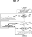
- FIG. 17 is an example of a flow chart illustrating the steps of a process of changing the screen configuration information without using the icon layout template information.
- the screen reproduction unit 105 displays, for example, an edit screen including the initial screen based on the screen configuration information acquired by the screen configuration acquiring unit 101 (step S 301 ).
- the edit screen includes, for example, a display area G 510 , and a menu area G 520 .
- the display area. G 510 is an area where the initial screen G 400 is reproduced based on the screen configuration information. That is, the display area G 510 displays the initial screen G 400 in the same manner that the initial screen G 400 is displayed on the operation panel 35 of the image forming apparatus 20 .
- the menu area G 520 is an area where various menus are displayed.
- the screen reproduction unit 105 determines whether the change instruction regarding the configuration of the initial screen G 400 is input by the user (step S 302 ).
- step S 302 If the user inputs the change instruction of the configuration of the initial screen G 400 (step S 302 : YES), the screen configuration changing unit 106 applies a change corresponding to the change instruction to the screen configuration information acquired by the screen configuration acquiring unit 101 (step S 303 ). With this configuration, the screen configuration information is changed in accordance with the change instruction input by the user.
- steps S 304 to S 307 are performed. Since steps S 304 to S 307 are similar to steps S 207 to S 210 in FIG. 10 , the description thereof is omitted.
- the user terminal 10 can also change the screen configuration information without using the icon layout template information.
- the screen configuration information can be stored in the screen configuration storage unit 109 or the screen configuration storage unit 204 in association with identification information (e.g., user ID) of each user.
- identification information e.g., user ID
- a user ID can be included in the screen configuration information.
- the user ID can be designated together with the acquisition destination of the screen configuration information when starting the sequence of FIG. 6 .
- the screen configuration acquiring unit 101 can acquire the screen configuration information corresponding to the designated user ID.
- Processing circuitry includes a programmed processor, as a processor includes circuitry.
- a processing circuit also includes devices such as an application specific integrated circuit (ASIC), digital signal processor (DSP), field programmable gate array (FPGA), system on a chip (SOC), graphics processing unit (GPU), and conventional circuit components arranged to perform the recited functions.
- ASIC application specific integrated circuit
- DSP digital signal processor
- FPGA field programmable gate array
- SOC system on a chip
- GPU graphics processing unit
- conventional circuit components arranged to perform the recited functions.
Abstract
Description
Claims (20)
Applications Claiming Priority (2)
| Application Number | Priority Date | Filing Date | Title |
|---|---|---|---|
| JP2017-211044 | 2017-10-31 | ||
| JP2017211044A JP6950461B2 (en) | 2017-10-31 | 2017-10-31 | Information processing equipment, information processing system and information processing method |
Publications (2)
| Publication Number | Publication Date |
|---|---|
| US20190132459A1 US20190132459A1 (en) | 2019-05-02 |
| US10863044B2 true US10863044B2 (en) | 2020-12-08 |
Family
ID=66244559
Family Applications (1)
| Application Number | Title | Priority Date | Filing Date |
|---|---|---|---|
| US16/161,183 Active US10863044B2 (en) | 2017-10-31 | 2018-10-16 | Information processing apparatus, information processing system, and method of processing information |
Country Status (2)
| Country | Link |
|---|---|
| US (1) | US10863044B2 (en) |
| JP (1) | JP6950461B2 (en) |
Families Citing this family (1)
| Publication number | Priority date | Publication date | Assignee | Title |
|---|---|---|---|---|
| JP2022179916A (en) * | 2021-05-24 | 2022-12-06 | セイコーエプソン株式会社 | Compound machine, control method for compound machine, and control program |
Citations (11)
| Publication number | Priority date | Publication date | Assignee | Title |
|---|---|---|---|---|
| US20020122061A1 (en) * | 1998-04-30 | 2002-09-05 | Bruce K. Martin | Configurable man-machine interface |
| US20050270565A1 (en) * | 2004-05-10 | 2005-12-08 | Seiko Epson Corporation | Distributed printing control device and print job distribution method |
| US20080141148A1 (en) * | 2006-12-08 | 2008-06-12 | Ogita Seiya | Image forming device and display control method |
| US7451404B1 (en) * | 2001-08-06 | 2008-11-11 | At&T Intellectual Property I, L.P. | Methods and systems for obtaining data from legacy computer systems |
| US20090063136A1 (en) | 2007-08-31 | 2009-03-05 | Ricoh Company, Ltd. | Information processing apparatus, information processing method, and information processing program |
| US20130314299A1 (en) | 2012-05-28 | 2013-11-28 | Ricoh Company, Ltd. | Information display device and information display method |
| US20140223570A1 (en) | 2013-02-06 | 2014-08-07 | Ricoh Company, Ltd. | Information processing apparatus, information processing system, and license management method |
| US20150015909A1 (en) | 2013-07-10 | 2015-01-15 | Yukiko Kaida | Image management system and image management apparatus |
| US20160028907A1 (en) * | 2014-07-22 | 2016-01-28 | Kabushiki Kaisha Toshiba | Image processing apparatus and method of displaying object in image processing apparatus |
| US20160248921A1 (en) | 2015-02-23 | 2016-08-25 | Yuichi Niwa | Information processing apparatus, information processing system, information processing method, and a computer program product |
| US20180041650A1 (en) | 2015-05-14 | 2018-02-08 | Ricoh Company, Ltd. | Apparatus, information processing method, and computer program product |
Family Cites Families (2)
| Publication number | Priority date | Publication date | Assignee | Title |
|---|---|---|---|---|
| JP5169174B2 (en) * | 2006-12-08 | 2013-03-27 | 株式会社リコー | Image forming apparatus, display control method, and display control program |
| JP2017129968A (en) * | 2016-01-19 | 2017-07-27 | 株式会社リコー | Operating device, image forming apparatus, image forming system, and program |
-
2017
- 2017-10-31 JP JP2017211044A patent/JP6950461B2/en active Active
-
2018
- 2018-10-16 US US16/161,183 patent/US10863044B2/en active Active
Patent Citations (12)
| Publication number | Priority date | Publication date | Assignee | Title |
|---|---|---|---|---|
| US20020122061A1 (en) * | 1998-04-30 | 2002-09-05 | Bruce K. Martin | Configurable man-machine interface |
| US7451404B1 (en) * | 2001-08-06 | 2008-11-11 | At&T Intellectual Property I, L.P. | Methods and systems for obtaining data from legacy computer systems |
| US20050270565A1 (en) * | 2004-05-10 | 2005-12-08 | Seiko Epson Corporation | Distributed printing control device and print job distribution method |
| US20080141148A1 (en) * | 2006-12-08 | 2008-06-12 | Ogita Seiya | Image forming device and display control method |
| US20090063136A1 (en) | 2007-08-31 | 2009-03-05 | Ricoh Company, Ltd. | Information processing apparatus, information processing method, and information processing program |
| US20130314299A1 (en) | 2012-05-28 | 2013-11-28 | Ricoh Company, Ltd. | Information display device and information display method |
| US20140223570A1 (en) | 2013-02-06 | 2014-08-07 | Ricoh Company, Ltd. | Information processing apparatus, information processing system, and license management method |
| US20150015909A1 (en) | 2013-07-10 | 2015-01-15 | Yukiko Kaida | Image management system and image management apparatus |
| US20160028907A1 (en) * | 2014-07-22 | 2016-01-28 | Kabushiki Kaisha Toshiba | Image processing apparatus and method of displaying object in image processing apparatus |
| US20160248921A1 (en) | 2015-02-23 | 2016-08-25 | Yuichi Niwa | Information processing apparatus, information processing system, information processing method, and a computer program product |
| JP2016157156A (en) | 2015-02-23 | 2016-09-01 | 株式会社リコー | Information processing apparatus, information processing system, information processing method, and program |
| US20180041650A1 (en) | 2015-05-14 | 2018-02-08 | Ricoh Company, Ltd. | Apparatus, information processing method, and computer program product |
Also Published As
| Publication number | Publication date |
|---|---|
| JP2019082948A (en) | 2019-05-30 |
| US20190132459A1 (en) | 2019-05-02 |
| JP6950461B2 (en) | 2021-10-13 |
Similar Documents
| Publication | Publication Date | Title |
|---|---|---|
| US10180849B2 (en) | Apparatus, information processing system, information processing method, and computer program product | |
| KR20100052409A (en) | Image processing apparatus, method of controlling the same, and storage medium | |
| US9712690B2 (en) | Information processing apparatus, information processing system, information processing method, and a computer program product | |
| JP6787115B2 (en) | Image forming device, function addition method, program, | |
| US10338797B2 (en) | Information processing apparatus and information processing method | |
| JP2012194622A (en) | Printer controller and driver program | |
| JP2011070472A (en) | Method, system and program for supporting development of application | |
| JP6819196B2 (en) | Information processing equipment and programs | |
| WO2014136429A1 (en) | Information processing apparatus and method for the same | |
| US10863044B2 (en) | Information processing apparatus, information processing system, and method of processing information | |
| CN105812348A (en) | Image forming apparatus and control method for same | |
| JP6717402B2 (en) | Information processing device, recording system, print program, and external program | |
| US9794437B2 (en) | Information processing apparatus, information processing system, and information processing method | |
| US20180249022A1 (en) | System and method for remote device interface customization | |
| US10785376B2 (en) | Image processing apparatus for sending user interface data | |
| JP2016099753A (en) | Terminal device, printer control method, and computer program | |
| JP2019016857A (en) | Image forming apparatus and program | |
| US10425547B2 (en) | System and method for selecting and implementing one or more user customized MFP interfaces | |
| JP6627583B2 (en) | Device, information processing system, display control method, and program | |
| JP6520405B2 (en) | Mobile terminal, content designation program, and output program | |
| US11165925B2 (en) | API for printing apparatus functions | |
| JP7346937B2 (en) | Information processing device, information processing method, program, image forming system | |
| JP6711438B2 (en) | Mobile terminal and output program | |
| JP6273756B2 (en) | Device driver, information processing apparatus, and output setting conversion method | |
| JP6696609B2 (en) | Mobile terminal and output program |
Legal Events
| Date | Code | Title | Description |
|---|---|---|---|
| AS | Assignment |
Owner name: RICOH COMPANY, LTD., JAPAN Free format text: ASSIGNMENT OF ASSIGNORS INTEREST;ASSIGNOR:KAIDA, YUKIKO;REEL/FRAME:047173/0066 Effective date: 20181010 |
|
| FEPP | Fee payment procedure |
Free format text: ENTITY STATUS SET TO UNDISCOUNTED (ORIGINAL EVENT CODE: BIG.); ENTITY STATUS OF PATENT OWNER: LARGE ENTITY |
|
| STPP | Information on status: patent application and granting procedure in general |
Free format text: NON FINAL ACTION MAILED |
|
| STPP | Information on status: patent application and granting procedure in general |
Free format text: RESPONSE TO NON-FINAL OFFICE ACTION ENTERED AND FORWARDED TO EXAMINER |
|
| STPP | Information on status: patent application and granting procedure in general |
Free format text: FINAL REJECTION MAILED |
|
| STPP | Information on status: patent application and granting procedure in general |
Free format text: NON FINAL ACTION MAILED |
|
| STPP | Information on status: patent application and granting procedure in general |
Free format text: FINAL REJECTION MAILED |
|
| STPP | Information on status: patent application and granting procedure in general |
Free format text: RESPONSE AFTER FINAL ACTION FORWARDED TO EXAMINER |
|
| STPP | Information on status: patent application and granting procedure in general |
Free format text: DOCKETED NEW CASE - READY FOR EXAMINATION |
|
| STPP | Information on status: patent application and granting procedure in general |
Free format text: NOTICE OF ALLOWANCE MAILED -- APPLICATION RECEIVED IN OFFICE OF PUBLICATIONS |
|
| STCF | Information on status: patent grant |
Free format text: PATENTED CASE |