US10859480B2 - System and method for determining linear density of carbon fiber - Google Patents
System and method for determining linear density of carbon fiber Download PDFInfo
- Publication number
- US10859480B2 US10859480B2 US15/920,175 US201815920175A US10859480B2 US 10859480 B2 US10859480 B2 US 10859480B2 US 201815920175 A US201815920175 A US 201815920175A US 10859480 B2 US10859480 B2 US 10859480B2
- Authority
- US
- United States
- Prior art keywords
- carbon fiber
- fiber tow
- air
- pulse
- linear density
- Prior art date
- Legal status (The legal status is an assumption and is not a legal conclusion. Google has not performed a legal analysis and makes no representation as to the accuracy of the status listed.)
- Active, expires
Links
- 229920000049 Carbon (fiber) Polymers 0.000 title claims abstract description 82
- 239000004917 carbon fiber Substances 0.000 title claims abstract description 82
- VNWKTOKETHGBQD-UHFFFAOYSA-N methane Chemical compound C VNWKTOKETHGBQD-UHFFFAOYSA-N 0.000 title claims abstract description 82
- 238000000034 method Methods 0.000 title claims abstract description 24
- 238000006073 displacement reaction Methods 0.000 claims abstract description 25
- 230000004044 response Effects 0.000 claims abstract description 8
- 238000005316 response function Methods 0.000 claims description 7
- 238000005259 measurement Methods 0.000 description 12
- 238000010586 diagram Methods 0.000 description 4
- 238000013500 data storage Methods 0.000 description 2
- 229920002239 polyacrylonitrile Polymers 0.000 description 2
- 230000006835 compression Effects 0.000 description 1
- 238000007906 compression Methods 0.000 description 1
- 238000010276 construction Methods 0.000 description 1
- 230000005284 excitation Effects 0.000 description 1
- 239000000835 fiber Substances 0.000 description 1
- 238000007380 fibre production Methods 0.000 description 1
- 238000004519 manufacturing process Methods 0.000 description 1
- 230000003287 optical effect Effects 0.000 description 1
Images


Classifications
-
- G—PHYSICS
- G01—MEASURING; TESTING
- G01N—INVESTIGATING OR ANALYSING MATERIALS BY DETERMINING THEIR CHEMICAL OR PHYSICAL PROPERTIES
- G01N9/00—Investigating density or specific gravity of materials; Analysing materials by determining density or specific gravity
- G01N9/36—Analysing materials by measuring the density or specific gravity, e.g. determining quantity of moisture
-
- G—PHYSICS
- G01—MEASURING; TESTING
- G01N—INVESTIGATING OR ANALYSING MATERIALS BY DETERMINING THEIR CHEMICAL OR PHYSICAL PROPERTIES
- G01N9/00—Investigating density or specific gravity of materials; Analysing materials by determining density or specific gravity
-
- G—PHYSICS
- G01—MEASURING; TESTING
- G01L—MEASURING FORCE, STRESS, TORQUE, WORK, MECHANICAL POWER, MECHANICAL EFFICIENCY, OR FLUID PRESSURE
- G01L5/00—Apparatus for, or methods of, measuring force, work, mechanical power, or torque, specially adapted for specific purposes
- G01L5/04—Apparatus for, or methods of, measuring force, work, mechanical power, or torque, specially adapted for specific purposes for measuring tension in flexible members, e.g. ropes, cables, wires, threads, belts or bands
Definitions
- Embodiments relate to determining one or more characteristics of carbon fiber, and more specifically, carbon fiber tow.
- Carbon fiber, and more specifically, carbon fiber tow is used in a variety of industries. Carbon fiber tow may be provided in spools having strands of carbon fiber. Carbon fiber production may be a complex process. Thus, during production, characteristics (for example, linear density) of the carbon fiber may vary.
- one embodiment provides a method for determining a linear density of a carbon fiber tow.
- the method includes providing a pulse of air directed toward the carbon fiber tow, determining, via a first sensor, an air pressure of the pulse of air, and measuring, via a second sensor, a displacement of the carbon fiber tow in response to the pulse of air directed toward the carbon fiber tow.
- the method further includes calculating, via a controller, a linear density of the carbon fiber tow based on the air pressure and the displacement, and outputting, via the controller, the linear density.
- the system includes an air source, a first sensor, a second sensor, and a controller.
- the air source is configured to direct a pulse of air toward the carbon fiber tow.
- the first sensor is configured to sense a pressure of the pulse of air.
- the second sensor is configured to sense a displacement of the carbon fiber tow in response to the pulse of air.
- the controller includes an electronic processor and memory. The controller is configured to receive the pressure of the pulse of air, receive the displacement of the carbon fiber tow, calculate a linear density of the carbon fiber tow based on the pressure and the displacement, and output the linear density.
- FIG. 1 is a block diagram of a system for determining one or more characteristics of carbon fiber according to some embodiments.
- FIG. 2 is a block diagram of an air source for the system of FIG. 1 according to some embodiments.
- FIG. 3 is a block diagram of a control system of the system of FIG. 1 according to some embodiments
- FIG. 4 is a chart illustrating a displacement of a carbon fiber tow over time.
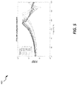
- FIG. 5 is a chart illustrating one or more frequency response functions (FRFs) of the carbon fiber tow.
- FIG. 6 is a flowchart illustrating a method or process of the system of FIG. 1 according to some embodiments.
- FIG. 1 illustrates a system 100 according to some embodiments.
- the system 100 is configured to determine one or more characteristics of a carbon fiber tow 105 .
- the one more characteristics include a linear density and/or a tension of the carbon fiber tow 105 .
- the carbon fiber tow 105 is 24 k carbon fiber tow.
- the system 100 may be configured to determine one or more characteristics of poly acrylonitrile (PAN) fiber.
- PAN poly acrylonitrile
- the system 100 may include first and second rollers 110 a , 110 b , an air pulse device 115 , and a measurement device 120 .
- the first and second rollers 110 a , 110 b are configured to roll the carbon fiber tow 105 past the air pulse device 115 and the measurement device 120 .
- the air pulse device 115 is configured to provide one or more pulses of air toward the carbon fiber tow 105 .
- the air pulse device 115 may include an air source 125 , a valve 130 , an air output 135 , and a pressure sensor 140 .
- the air source 125 may be any known air source, including but not limited to, an air tank and an air compression.
- the valve 130 is configured to control the air from the air source 125 to the air output 135 .
- the valve 130 may be an electrically-controlled valve having a variable opening speed.
- the air (for example, in the form of a pulse of air) may be directed toward the carbon fiber tow 105 via the air output 135 .
- the pressure sensor 140 is configured to sense the pressure of the air directed toward the carbon fiber tow 105 .
- the pressure sensor 140 is a transducer.
- the pressure sensor 140 may be a Pitot tube pressure sensor.
- FIG. 2 illustrates the air pulse device 115 according to some embodiments.
- the air pulse device 115 may have a first valve 130 a and a second valve 130 b .
- the pulse width, or duration, of the air pulse may be controlled by controlling an offset time of the first and second valves 130 a , 130 b .
- the first valve 130 a is a normally closed valve
- the second valve 130 b is a normally open valve.
- the first valve 130 a may be in a normally closed position and opens upon receiving a voltage signal
- the second valve 130 b may be in a normally open position and closes upon receiving a voltage signal.
- pulse-width signals 145 , 150 may be used to control the offset time between the first and second valves 130 a , 130 b , and thus the duration of the air pulse output from the air output 135 .
- pulse-width signal 145 may open the normally closed first valve 130 a for a first time period (illustrated as arrow 155 ), while pulse-width signal 150 may close the normally open second valve 130 b for a second time period (illustrated as arrow 160 ).
- the duration of the air pulse output from the air output 135 may have a third time period (illustrated as arrow 165 ) approximately equivalent to a start time of the first time period and a start time of the second time period.
- Such an embodiment may allow pulses of air having a shorter duration than pulses of air provided by a single valve.
- the measurement device 120 is configured to measure a displacement of the carbon fiber tow 105 in response to the carbon fiber tow 105 receiving the one or more air pulses from the air pulse device 115 .
- the measurement device 120 may be a transducer, such as but not limited to, an ultrasonic transducer, a laser transducer, an electroacoustic transducer, and an electro-optical transducer.
- the measurement device 120 outputs a signal (for example, an ultrasonic signal, a laser signal, etc.) toward the carbon fiber tow 105 .
- the signal is then reflected off of the carbon fiber tow 105 .
- the measurement device 120 receives the reflected signal to determine/sense displacement of the carbon fiber tow 105 .
- FIG. 3 is a block diagram of a control system 200 of the system 100 according to some embodiments.
- the control system 200 is configured to control operation of the system 100 .
- the control system 200 includes a controller 205 that is electrically and/or communicatively connected to a variety of modules or components of the system 100 .
- the controller 205 is electrically and/or communicatively connected to the air pulse device 115 (including, but not limited to, valve 130 and pressure sensor 140 ) and the measurement device 120 .
- the controller 205 includes a plurality of electrical and electronic components that provide power, operational control, and protection to the components and modules within the controller 205 and/or the system 100 .
- the controller 205 includes, among other things, an electronic processor 210 (for example, a microprocessor or another suitable programmable device) and the memory 215 .
- the memory 215 includes, for example, a program storage area and a data storage area.
- the program storage area and the data storage area can include combinations of different types of memory, such as read-only memory (ROM), random access memory (RAM).
- ROM read-only memory
- RAM random access memory
- Various non-transitory computer readable media for example, magnetic, optical, physical, or electronic memory may be used.
- the electronic processor 210 is communicatively coupled to the memory 215 and executes software instructions that are stored in the memory 215 , or stored on another non-transitory computer readable medium such as another memory or a disc.
- the software may include one or more applications, program data, filters, rules, one or more program modules, and other executable instructions.
- control system 200 further includes an input/output (I/O) interface 220 .
- I/O interface 220 provides an interface between system 100 and external devices (for example, a display, an external computer, a network, a smartphone, etc.).
- controller 205 controls the air pulse device 115 by outputting one or more control signals (for example, pulse-width signals 145 , 150 ) to valve 130 (for example, first and second valves 130 a , 130 b ).
- the controller 205 may then receive one or more pressure signals from the pressure sensor 140 , indicative of the pressures of one or more air pulses directed toward the carbon fiber tow 105 .
- the controller 205 may also then receive one or more measurement signals, from the measurement device 120 , indicative of the displacement of the carbon fiber tow 105 .
- the controller 205 may then determine one or more characteristics of the carbon fiber tow 105 based on the pressure and measurement signals.
- the controller 205 may then output the one or more characteristics via the I/O interface 220 .
- FIG. 4 is chart 300 illustrating a displacement of the carbon fiber tow 105 over time according to some embodiments.
- a similar chart may illustrate a pressure of the one or more air pulses directed toward the carbon fiber tow 105 over time.
- FIG. 5 is a chart 400 illustrating one or more frequency response functions (FRFs) of the carbon fiber tow 105 .
- the one or more FRFs of the carbon fiber tow 105 may be calculated, by the controller 205 , based on the displacement and the pressure.
- a 0 Hz component of the FRF (FRF(0)) of the carbon fiber tow 105 is calculated.
- FRF(0) may then be used to determine a tension of the carbon fiber tow 105 , using Equations 1.
- L may represent the length of the tow
- x o may represent the location of the excitation force (for example, the position of the air pulse device 115 )
- x may represent the location at which the response is measured (for example, the position of the measurement device 120 )
- FRF(0) may represent the FRF at 0 Hz
- T may represent the tension.
- one or more natural frequencies of the carbon fiber tow 105 may be determined.
- a modal parameter estimation algorithm is used to determine/identify the natural frequencies of the carbon fiber tow 105 .
- a linear density of the carbon fiber tow 105 may be calculated using Equation 2 below, where f n is the nth natural frequency of the tow (determined using the FRF), T is the tension of the tow 105 (determined based on the FRF(0)), L is the length of the tow 105 , and p is the linear density of the tow.
- FIG. 6 is a flowchart illustrating an operation, or process, 500 of the system 100 according to some embodiments. It should be understood that the order of the steps disclosed in process 500 could vary. In addition, other steps may be added and not all of the steps may be required.
- a pulse of air is directed toward the carbon fiber tow 105 (block 505 ).
- the pulse of air is provided by the air pulse device 115 at a predetermined position.
- a pressure of the pulse of air directed toward the carbon fiber tow 105 is then determined (block 510 ). In some embodiments, the pressure is determined via a first sensor (for example, pressure sensor 140 ).
- a displacement of the carbon fiber tow 105 in response to the pulse of air is then determined (block 515 ).
- the displacement is determined via a second sensor (for example, measurement device 120 ).
- a linear density of the carbon fiber tow 105 is determined based on the pressure and the displacement (block 520 ).
- the linear density is determined by controller 205 .
- the linear density is determined based on a calculated frequency response function (FRF) of the carbon fiber tow 105 .
- the linear density is determined by controller 205 .
- the linear density may then be output (block 525 ).
- the invention provides, among other things, a system and method for determining a linear density of a carbon fiber tow.
- a system and method for determining a linear density of a carbon fiber tow are set forth in the following claims.
Landscapes
- Physics & Mathematics (AREA)
- General Physics & Mathematics (AREA)
- Health & Medical Sciences (AREA)
- Life Sciences & Earth Sciences (AREA)
- Chemical & Material Sciences (AREA)
- Analytical Chemistry (AREA)
- Biochemistry (AREA)
- General Health & Medical Sciences (AREA)
- Immunology (AREA)
- Pathology (AREA)
- Measuring Fluid Pressure (AREA)
- Inorganic Fibers (AREA)
Abstract
Description
Claims (20)
Priority Applications (1)
| Application Number | Priority Date | Filing Date | Title |
|---|---|---|---|
| US15/920,175 US10859480B2 (en) | 2017-03-14 | 2018-03-13 | System and method for determining linear density of carbon fiber |
Applications Claiming Priority (2)
| Application Number | Priority Date | Filing Date | Title |
|---|---|---|---|
| US201762471037P | 2017-03-14 | 2017-03-14 | |
| US15/920,175 US10859480B2 (en) | 2017-03-14 | 2018-03-13 | System and method for determining linear density of carbon fiber |
Publications (2)
| Publication Number | Publication Date |
|---|---|
| US20180266929A1 US20180266929A1 (en) | 2018-09-20 |
| US10859480B2 true US10859480B2 (en) | 2020-12-08 |
Family
ID=63519954
Family Applications (1)
| Application Number | Title | Priority Date | Filing Date |
|---|---|---|---|
| US15/920,175 Active 2039-08-15 US10859480B2 (en) | 2017-03-14 | 2018-03-13 | System and method for determining linear density of carbon fiber |
Country Status (1)
| Country | Link |
|---|---|
| US (1) | US10859480B2 (en) |
Cited By (7)
| Publication number | Priority date | Publication date | Assignee | Title |
|---|---|---|---|---|
| US11101421B2 (en) | 2019-02-25 | 2021-08-24 | Birmingham Technologies, Inc. | Nano-scale energy conversion device |
| US11124864B2 (en) | 2019-05-20 | 2021-09-21 | Birmingham Technologies, Inc. | Method of fabricating nano-structures with engineered nano-scale electrospray depositions |
| US11244816B2 (en) | 2019-02-25 | 2022-02-08 | Birmingham Technologies, Inc. | Method of manufacturing and operating nano-scale energy conversion device |
| US11417506B1 (en) | 2020-10-15 | 2022-08-16 | Birmingham Technologies, Inc. | Apparatus including thermal energy harvesting thermionic device integrated with electronics, and related systems and methods |
| US11616186B1 (en) | 2021-06-28 | 2023-03-28 | Birmingham Technologies, Inc. | Thermal-transfer apparatus including thermionic devices, and related methods |
| US11649525B2 (en) | 2020-05-01 | 2023-05-16 | Birmingham Technologies, Inc. | Single electron transistor (SET), circuit containing set and energy harvesting device, and fabrication method |
| US11715852B2 (en) | 2014-02-13 | 2023-08-01 | Birmingham Technologies, Inc. | Nanofluid contact potential difference battery |
Families Citing this family (3)
| Publication number | Priority date | Publication date | Assignee | Title |
|---|---|---|---|---|
| US10690485B2 (en) | 2017-03-14 | 2020-06-23 | Vanderbilt University | System and method for determining tow parameters |
| CN111294692A (en) * | 2020-04-27 | 2020-06-16 | 深圳市友杰智新科技有限公司 | Tuning method of earphone, computer equipment and storage medium |
| CN113252225A (en) * | 2021-04-13 | 2021-08-13 | 武汉纺织大学 | Bundling tension detection system |
Citations (25)
| Publication number | Priority date | Publication date | Assignee | Title |
|---|---|---|---|---|
| US5052233A (en) * | 1988-09-14 | 1991-10-01 | Valmet Paper Machinery Inc. | Method and apparatus for measurement of web tension |
| US5057338A (en) * | 1990-05-16 | 1991-10-15 | The United States Of America As Represented By The Administrator Of The National Aeronautics And Space Administration | Process for application of powder particles to filamentary materials |
| US5123373A (en) * | 1990-02-26 | 1992-06-23 | Board Of Trustees Operating Michigan State University | Method for fiber coating with particles |
| US5228893A (en) * | 1991-11-27 | 1993-07-20 | At&T Bell Laboratories | Optical fiber tension monitoring technique |
| US5296064A (en) * | 1989-04-17 | 1994-03-22 | Georgia Tech Research Corp. | Flexible multiply towpreg tape from powder fusion coated towpreg and method for production thereof |
| US5436980A (en) * | 1988-05-10 | 1995-07-25 | E. I. Du Pont De Nemours And Company | Method for determining quality of dispersion of glass fibers in a thermoplastic resin preform layer and preform layer characterized thereby |
| US5710432A (en) * | 1996-01-18 | 1998-01-20 | Alcatel Na Cable Systems, Inc. | Non-contact tension measurement of moving fiber using traveling wave time-of-flight analysis |
| JP2004294186A (en) | 2003-03-26 | 2004-10-21 | Osaka Gas Co Ltd | Thickness measurement method, thickness control method, manufacturing method, and manufacturing equipment for extra-fine carbon fiber collection |
| US6813941B2 (en) * | 2001-12-20 | 2004-11-09 | Kimberly-Clark Worldwide, Inc. | Method to measure tension in a moving web and to control properties of the web |
| JP2006265791A (en) | 2005-03-25 | 2006-10-05 | Teijin Techno Products Ltd | Method for detecting fuzz and fuzz detector |
| CN200947079Y (en) | 2006-09-07 | 2007-09-12 | 郭会清 | Vertical tow linear density tester |
| US20070230721A1 (en) * | 2006-01-23 | 2007-10-04 | White Robert D | Trapped fluid microsystems for acoustic sensing |
| US20070272563A1 (en) * | 2005-06-08 | 2007-11-29 | Adrian Petyt | Biosensors and Methods of Preparing Same |
| US20120086566A1 (en) * | 2009-06-29 | 2012-04-12 | Michelin Recherche Et Technique | System and method for evaluating surface finish of tire retread |
| KR20120077537A (en) | 2010-12-30 | 2012-07-10 | 주식회사 효성 | Width measuring device of filament tow and measuring method using it |
| CN203148713U (en) | 2013-03-28 | 2013-08-21 | 安徽首文碳纤维有限公司 | Testing and sampling device for carbon fiber tow linear density |
| US20140009599A1 (en) * | 2012-07-03 | 2014-01-09 | Applied Nanostructure Solutions, Llc. | Methods and systems for monitoring the growth of carbon nanostructures on a substrate |
| US20140069893A1 (en) * | 2012-09-12 | 2014-03-13 | Gerald J. Bruck | Automated superalloy laser cladding with 3d imaging weld path control |
| CN203908901U (en) | 2013-12-31 | 2014-10-29 | 武汉理工大学 | On-line measurement device for linear density of glass fiber |
| US20150251213A1 (en) * | 2013-05-17 | 2015-09-10 | Joseph G. Birmingham | Electrospray pinning of nanograined depositions |
| CN205403670U (en) | 2016-03-21 | 2016-07-27 | 刘萍 | Cotton fiber thickness detection achievement platform |
| US20160322306A1 (en) * | 2015-04-28 | 2016-11-03 | Infineon Technologies Ag | Integrated Circuit Substrate and Method for Manufacturing the Same |
| US20160332389A1 (en) * | 2014-01-09 | 2016-11-17 | Toyota Motor Europe Nv/Sa | Reinforced plastic material having high smoothness |
| CN205748285U (en) | 2016-05-10 | 2016-11-30 | 哈尔滨理工大学 | Cotton fiber diameter measuring device based on transmission grating |
| US20180266811A1 (en) * | 2017-03-14 | 2018-09-20 | Vanderbilt University | System and method for determining tow parameters |
-
2018
- 2018-03-13 US US15/920,175 patent/US10859480B2/en active Active
Patent Citations (25)
| Publication number | Priority date | Publication date | Assignee | Title |
|---|---|---|---|---|
| US5436980A (en) * | 1988-05-10 | 1995-07-25 | E. I. Du Pont De Nemours And Company | Method for determining quality of dispersion of glass fibers in a thermoplastic resin preform layer and preform layer characterized thereby |
| US5052233A (en) * | 1988-09-14 | 1991-10-01 | Valmet Paper Machinery Inc. | Method and apparatus for measurement of web tension |
| US5296064A (en) * | 1989-04-17 | 1994-03-22 | Georgia Tech Research Corp. | Flexible multiply towpreg tape from powder fusion coated towpreg and method for production thereof |
| US5123373A (en) * | 1990-02-26 | 1992-06-23 | Board Of Trustees Operating Michigan State University | Method for fiber coating with particles |
| US5057338A (en) * | 1990-05-16 | 1991-10-15 | The United States Of America As Represented By The Administrator Of The National Aeronautics And Space Administration | Process for application of powder particles to filamentary materials |
| US5228893A (en) * | 1991-11-27 | 1993-07-20 | At&T Bell Laboratories | Optical fiber tension monitoring technique |
| US5710432A (en) * | 1996-01-18 | 1998-01-20 | Alcatel Na Cable Systems, Inc. | Non-contact tension measurement of moving fiber using traveling wave time-of-flight analysis |
| US6813941B2 (en) * | 2001-12-20 | 2004-11-09 | Kimberly-Clark Worldwide, Inc. | Method to measure tension in a moving web and to control properties of the web |
| JP2004294186A (en) | 2003-03-26 | 2004-10-21 | Osaka Gas Co Ltd | Thickness measurement method, thickness control method, manufacturing method, and manufacturing equipment for extra-fine carbon fiber collection |
| JP2006265791A (en) | 2005-03-25 | 2006-10-05 | Teijin Techno Products Ltd | Method for detecting fuzz and fuzz detector |
| US20070272563A1 (en) * | 2005-06-08 | 2007-11-29 | Adrian Petyt | Biosensors and Methods of Preparing Same |
| US20070230721A1 (en) * | 2006-01-23 | 2007-10-04 | White Robert D | Trapped fluid microsystems for acoustic sensing |
| CN200947079Y (en) | 2006-09-07 | 2007-09-12 | 郭会清 | Vertical tow linear density tester |
| US20120086566A1 (en) * | 2009-06-29 | 2012-04-12 | Michelin Recherche Et Technique | System and method for evaluating surface finish of tire retread |
| KR20120077537A (en) | 2010-12-30 | 2012-07-10 | 주식회사 효성 | Width measuring device of filament tow and measuring method using it |
| US20140009599A1 (en) * | 2012-07-03 | 2014-01-09 | Applied Nanostructure Solutions, Llc. | Methods and systems for monitoring the growth of carbon nanostructures on a substrate |
| US20140069893A1 (en) * | 2012-09-12 | 2014-03-13 | Gerald J. Bruck | Automated superalloy laser cladding with 3d imaging weld path control |
| CN203148713U (en) | 2013-03-28 | 2013-08-21 | 安徽首文碳纤维有限公司 | Testing and sampling device for carbon fiber tow linear density |
| US20150251213A1 (en) * | 2013-05-17 | 2015-09-10 | Joseph G. Birmingham | Electrospray pinning of nanograined depositions |
| CN203908901U (en) | 2013-12-31 | 2014-10-29 | 武汉理工大学 | On-line measurement device for linear density of glass fiber |
| US20160332389A1 (en) * | 2014-01-09 | 2016-11-17 | Toyota Motor Europe Nv/Sa | Reinforced plastic material having high smoothness |
| US20160322306A1 (en) * | 2015-04-28 | 2016-11-03 | Infineon Technologies Ag | Integrated Circuit Substrate and Method for Manufacturing the Same |
| CN205403670U (en) | 2016-03-21 | 2016-07-27 | 刘萍 | Cotton fiber thickness detection achievement platform |
| CN205748285U (en) | 2016-05-10 | 2016-11-30 | 哈尔滨理工大学 | Cotton fiber diameter measuring device based on transmission grating |
| US20180266811A1 (en) * | 2017-03-14 | 2018-09-20 | Vanderbilt University | System and method for determining tow parameters |
Cited By (7)
| Publication number | Priority date | Publication date | Assignee | Title |
|---|---|---|---|---|
| US11715852B2 (en) | 2014-02-13 | 2023-08-01 | Birmingham Technologies, Inc. | Nanofluid contact potential difference battery |
| US11101421B2 (en) | 2019-02-25 | 2021-08-24 | Birmingham Technologies, Inc. | Nano-scale energy conversion device |
| US11244816B2 (en) | 2019-02-25 | 2022-02-08 | Birmingham Technologies, Inc. | Method of manufacturing and operating nano-scale energy conversion device |
| US11124864B2 (en) | 2019-05-20 | 2021-09-21 | Birmingham Technologies, Inc. | Method of fabricating nano-structures with engineered nano-scale electrospray depositions |
| US11649525B2 (en) | 2020-05-01 | 2023-05-16 | Birmingham Technologies, Inc. | Single electron transistor (SET), circuit containing set and energy harvesting device, and fabrication method |
| US11417506B1 (en) | 2020-10-15 | 2022-08-16 | Birmingham Technologies, Inc. | Apparatus including thermal energy harvesting thermionic device integrated with electronics, and related systems and methods |
| US11616186B1 (en) | 2021-06-28 | 2023-03-28 | Birmingham Technologies, Inc. | Thermal-transfer apparatus including thermionic devices, and related methods |
Also Published As
| Publication number | Publication date |
|---|---|
| US20180266929A1 (en) | 2018-09-20 |
Similar Documents
| Publication | Publication Date | Title |
|---|---|---|
| US10859480B2 (en) | System and method for determining linear density of carbon fiber | |
| EP1336083B1 (en) | Method and device for determining and/or monitoring the level of a medium in a container, or for determining the density of a medium in a container | |
| EP3298359B1 (en) | Method for determining a pipe wall resonance frequency, and clamp-on-ultrasonic flowmeter | |
| DE102013227196A1 (en) | Three-mode sensor for determining a temperature, a level, and a concentration of a fluid | |
| WO2014198495A1 (en) | Measuring system having a pressure device and method for monitoring and/or checking such a pressure device | |
| DE102013106155A1 (en) | Measuring system with a pressure device and method for monitoring and / or checking such a pressure device | |
| WO2011138147A1 (en) | Method and device for determining flow properties of a medium in a pipeline | |
| AT515552B1 (en) | Method and device for determining a density value | |
| EP2729781A1 (en) | Method for testing the quality of a vacuum | |
| AT516281B1 (en) | Method for determining the degree of filling of a transducer tube of a bending vibrator and bending vibrator | |
| US20210072071A1 (en) | System and method for assessing transportation risk | |
| DE102005037458B4 (en) | Ultrasonic flow sensor with drift compensation | |
| DE102013106172A1 (en) | Method of calibration or adjustment of any oscillatable unit | |
| EP3144705A1 (en) | Information processing device, anomaly detection method and recording medium | |
| Theodoro et al. | Measurement uncertainty of a pressure sensor submitted to a step input | |
| US10549423B2 (en) | Controller and machine learning device | |
| DE102015007641B4 (en) | Method for measuring the distance of an object by means of an ultrasonic sensor | |
| DE19581067C2 (en) | Method and apparatus for detecting the residual amount of a gas in a cassette type gas cylinder | |
| EP3413028A1 (en) | Structural health monitoring and baseline deviation assessment | |
| DE102019209353B4 (en) | Diaphragm seal system with monitoring function | |
| US8848942B2 (en) | Acoustic beam forming array using feedback-controlled microphones for tuning and self-matching of frequency response | |
| DE102017102036A1 (en) | Device and method for monitoring the filling | |
| CN105806574A (en) | Method for determining vibration acceleration model based on dynamic stress test | |
| WO2020249163A1 (en) | Coriolis flow meter which compensates for viscosity-related measurement errors | |
| DE102019216499A1 (en) | Device and method for determining the consumption of a gas from a gas cylinder at least partially filled with gas |
Legal Events
| Date | Code | Title | Description |
|---|---|---|---|
| FEPP | Fee payment procedure |
Free format text: ENTITY STATUS SET TO UNDISCOUNTED (ORIGINAL EVENT CODE: BIG.); ENTITY STATUS OF PATENT OWNER: SMALL ENTITY |
|
| FEPP | Fee payment procedure |
Free format text: ENTITY STATUS SET TO SMALL (ORIGINAL EVENT CODE: SMAL); ENTITY STATUS OF PATENT OWNER: SMALL ENTITY |
|
| STPP | Information on status: patent application and granting procedure in general |
Free format text: DOCKETED NEW CASE - READY FOR EXAMINATION |
|
| AS | Assignment |
Owner name: VANDERBILT UNIVERSITY, TENNESSEE Free format text: ASSIGNMENT OF ASSIGNORS INTEREST;ASSIGNORS:KOESTER, DAVID J.;ADAMS, DOUGLAS;BOND, RAYMOND MARTIN;AND OTHERS;SIGNING DATES FROM 20180314 TO 20180318;REEL/FRAME:045699/0364 |
|
| AS | Assignment |
Owner name: UNITED STATES DEPARTMENT OF ENERGY, DISTRICT OF CO Free format text: CONFIRMATORY LICENSE;ASSIGNOR:VANDERBILT UNIVERSITY;REEL/FRAME:051100/0775 Effective date: 20190819 Owner name: UNITED STATES DEPARTMENT OF ENERGY, DISTRICT OF COLUMBIA Free format text: CONFIRMATORY LICENSE;ASSIGNOR:VANDERBILT UNIVERSITY;REEL/FRAME:051100/0775 Effective date: 20190819 |
|
| STPP | Information on status: patent application and granting procedure in general |
Free format text: NOTICE OF ALLOWANCE MAILED -- APPLICATION RECEIVED IN OFFICE OF PUBLICATIONS |
|
| STPP | Information on status: patent application and granting procedure in general |
Free format text: PUBLICATIONS -- ISSUE FEE PAYMENT VERIFIED |
|
| STCF | Information on status: patent grant |
Free format text: PATENTED CASE |
|
| MAFP | Maintenance fee payment |
Free format text: PAYMENT OF MAINTENANCE FEE, 4TH YR, SMALL ENTITY (ORIGINAL EVENT CODE: M2551); ENTITY STATUS OF PATENT OWNER: SMALL ENTITY Year of fee payment: 4 |