EP3298359B1 - Method for determining a pipe wall resonance frequency, and clamp-on-ultrasonic flowmeter - Google Patents
Method for determining a pipe wall resonance frequency, and clamp-on-ultrasonic flowmeter Download PDFInfo
- Publication number
- EP3298359B1 EP3298359B1 EP16718683.2A EP16718683A EP3298359B1 EP 3298359 B1 EP3298359 B1 EP 3298359B1 EP 16718683 A EP16718683 A EP 16718683A EP 3298359 B1 EP3298359 B1 EP 3298359B1
- Authority
- EP
- European Patent Office
- Prior art keywords
- ultrasonic
- pipe wall
- measuring point
- procedure
- transducer
- Prior art date
- Legal status (The legal status is an assumption and is not a legal conclusion. Google has not performed a legal analysis and makes no representation as to the accuracy of the status listed.)
- Active
Links
- 238000000034 method Methods 0.000 title claims description 48
- 230000006870 function Effects 0.000 claims description 57
- 238000005259 measurement Methods 0.000 claims description 38
- 238000001228 spectrum Methods 0.000 claims description 36
- 230000005540 biological transmission Effects 0.000 claims description 25
- 230000005284 excitation Effects 0.000 claims description 19
- 239000000463 material Substances 0.000 claims description 18
- 238000011156 evaluation Methods 0.000 claims description 12
- 230000008878 coupling Effects 0.000 claims description 7
- 238000010168 coupling process Methods 0.000 claims description 7
- 238000005859 coupling reaction Methods 0.000 claims description 7
- 230000008859 change Effects 0.000 claims description 5
- 238000005516 engineering process Methods 0.000 claims description 5
- 230000008569 process Effects 0.000 claims description 4
- 238000012546 transfer Methods 0.000 description 40
- 239000012530 fluid Substances 0.000 description 18
- 238000013016 damping Methods 0.000 description 10
- 230000001419 dependent effect Effects 0.000 description 7
- 230000006399 behavior Effects 0.000 description 3
- 238000004364 calculation method Methods 0.000 description 3
- 235000019687 Lamb Nutrition 0.000 description 2
- 238000010586 diagram Methods 0.000 description 2
- 239000003921 oil Substances 0.000 description 2
- 208000035874 Excoriation Diseases 0.000 description 1
- 244000089486 Phragmites australis subsp australis Species 0.000 description 1
- 229910000831 Steel Inorganic materials 0.000 description 1
- 238000005299 abrasion Methods 0.000 description 1
- 230000006978 adaptation Effects 0.000 description 1
- 238000005452 bending Methods 0.000 description 1
- 238000004422 calculation algorithm Methods 0.000 description 1
- 239000013078 crystal Substances 0.000 description 1
- 230000003247 decreasing effect Effects 0.000 description 1
- 238000000695 excitation spectrum Methods 0.000 description 1
- 230000002349 favourable effect Effects 0.000 description 1
- 238000009434 installation Methods 0.000 description 1
- 239000007788 liquid Substances 0.000 description 1
- 238000012423 maintenance Methods 0.000 description 1
- 238000012821 model calculation Methods 0.000 description 1
- 230000000750 progressive effect Effects 0.000 description 1
- 230000000644 propagated effect Effects 0.000 description 1
- 230000005855 radiation Effects 0.000 description 1
- 239000000523 sample Substances 0.000 description 1
- 230000005236 sound signal Effects 0.000 description 1
- 239000010959 steel Substances 0.000 description 1
- 230000009466 transformation Effects 0.000 description 1
- 238000011144 upstream manufacturing Methods 0.000 description 1
- XLYOFNOQVPJJNP-UHFFFAOYSA-N water Substances O XLYOFNOQVPJJNP-UHFFFAOYSA-N 0.000 description 1
Images
Classifications
-
- G—PHYSICS
- G01—MEASURING; TESTING
- G01F—MEASURING VOLUME, VOLUME FLOW, MASS FLOW OR LIQUID LEVEL; METERING BY VOLUME
- G01F1/00—Measuring the volume flow or mass flow of fluid or fluent solid material wherein the fluid passes through a meter in a continuous flow
- G01F1/66—Measuring the volume flow or mass flow of fluid or fluent solid material wherein the fluid passes through a meter in a continuous flow by measuring frequency, phase shift or propagation time of electromagnetic or other waves, e.g. using ultrasonic flowmeters
- G01F1/662—Constructional details
-
- G—PHYSICS
- G01—MEASURING; TESTING
- G01F—MEASURING VOLUME, VOLUME FLOW, MASS FLOW OR LIQUID LEVEL; METERING BY VOLUME
- G01F1/00—Measuring the volume flow or mass flow of fluid or fluent solid material wherein the fluid passes through a meter in a continuous flow
- G01F1/66—Measuring the volume flow or mass flow of fluid or fluent solid material wherein the fluid passes through a meter in a continuous flow by measuring frequency, phase shift or propagation time of electromagnetic or other waves, e.g. using ultrasonic flowmeters
- G01F1/667—Arrangements of transducers for ultrasonic flowmeters; Circuits for operating ultrasonic flowmeters
-
- G—PHYSICS
- G01—MEASURING; TESTING
- G01F—MEASURING VOLUME, VOLUME FLOW, MASS FLOW OR LIQUID LEVEL; METERING BY VOLUME
- G01F15/00—Details of, or accessories for, apparatus of groups G01F1/00 - G01F13/00 insofar as such details or appliances are not adapted to particular types of such apparatus
- G01F15/02—Compensating or correcting for variations in pressure, density or temperature
- G01F15/022—Compensating or correcting for variations in pressure, density or temperature using electrical means
- G01F15/024—Compensating or correcting for variations in pressure, density or temperature using electrical means involving digital counting
-
- G—PHYSICS
- G01—MEASURING; TESTING
- G01F—MEASURING VOLUME, VOLUME FLOW, MASS FLOW OR LIQUID LEVEL; METERING BY VOLUME
- G01F25/00—Testing or calibration of apparatus for measuring volume, volume flow or liquid level or for metering by volume
- G01F25/10—Testing or calibration of apparatus for measuring volume, volume flow or liquid level or for metering by volume of flowmeters
-
- G—PHYSICS
- G01—MEASURING; TESTING
- G01N—INVESTIGATING OR ANALYSING MATERIALS BY DETERMINING THEIR CHEMICAL OR PHYSICAL PROPERTIES
- G01N29/00—Investigating or analysing materials by the use of ultrasonic, sonic or infrasonic waves; Visualisation of the interior of objects by transmitting ultrasonic or sonic waves through the object
- G01N29/04—Analysing solids
- G01N29/12—Analysing solids by measuring frequency or resonance of acoustic waves
-
- G—PHYSICS
- G01—MEASURING; TESTING
- G01N—INVESTIGATING OR ANALYSING MATERIALS BY DETERMINING THEIR CHEMICAL OR PHYSICAL PROPERTIES
- G01N29/00—Investigating or analysing materials by the use of ultrasonic, sonic or infrasonic waves; Visualisation of the interior of objects by transmitting ultrasonic or sonic waves through the object
- G01N29/44—Processing the detected response signal, e.g. electronic circuits specially adapted therefor
- G01N29/4472—Mathematical theories or simulation
-
- G—PHYSICS
- G01—MEASURING; TESTING
- G01N—INVESTIGATING OR ANALYSING MATERIALS BY DETERMINING THEIR CHEMICAL OR PHYSICAL PROPERTIES
- G01N2291/00—Indexing codes associated with group G01N29/00
- G01N2291/26—Scanned objects
- G01N2291/263—Surfaces
- G01N2291/2634—Surfaces cylindrical from outside
Definitions
- the present invention relates to a method for determining at least one pipe wall resonance frequency and a clamp-on ultrasonic flowmeter, a method for determining a flow rate and/or a flow rate, a method for determining changes in a measuring point and a pipe identification device.
- Clamp-on ultrasonic flowmeters have been known for a long time. They can be operated according to the Doppler principle or according to the transit time difference principle.
- the ultrasonic transducers, also called ultrasonic transducers, of the clamp-on ultrasonic flowmeters are usually placed on an existing pipeline from the outside and strapped or otherwise fixed to the pipeline. The flow meter can thus be installed without interrupting the flow in the pipeline.
- the DE 1981 8053 A1 discloses an ultrasonic flow meter and method that ensures accurate determination of the arrival time of ultrasonic pulses in a flow medium by giving the signals received at the receiving transducer after transmission in both upstream and downstream directions through the flow medium the same relative assigns relationship. This enables a more precise flow measurement to be implemented.
- the accuracy of the flow measurement can also be influenced by the sound-absorbing properties of the different wall materials in the pipeline, as well as the inner lining or hydroabrasion. So far no suitable compensation is known for this source of error specific to the measuring point.
- the present invention solves this problem by a method having the features of claim 1 or 13.
- the invention makes it possible to provide a suitable clamp-on flowmeter and a pipe wall identification device with which pipeline parameters can be determined.
- the aforementioned transfer functions and the received signal can be represented as amplitude spectra, e.g. sound level in decibels as a function of a frequency.
- the transmission function which is characteristic of the measuring point, is mainly determined by the sound transmission behavior of the pipeline, including any deposits or similar. In the case of sound-damping media, however, the transfer behavior of the measuring medium can also be included in the transfer function.
- a received spectrum U rec (f) is detected from a received signal u rec (t) after the transmission of an ultrasonic signal.
- a time signal u rec (t) is measured and the complex-valued spectrum U rec (f) is then calculated from it in the form of a transfer function.
- the determined pipe wall resonance frequencies can be used in particular, but not exclusively, to correct a determined flow rate and/or a determined flow rate and/or for other evaluations, e.g. to predict a favorable measuring point, for maintenance and/or self-calibration of the ultrasonic flow meter and the like.
- the field device for process measurement technology has at least one data memory and the transmission function of the first or the plurality of ultrasonic transducers is stored in the data memory so that it can be called up.
- the transfer function of two ultrasonic transducers is provided by determining an overall transfer function by Ultrasonic transducers are connected to each other at their coupling surfaces.
- the overall transfer function thus describes the propagation of the sound signal through the first and the second ultrasonic transducer.
- a transfer function that is characteristic of the measuring point can advantageously be determined by subtracting the logarithmic amplitude spectra of the transfer function of at least the first or more ultrasonic transducers located in the area of the measuring point and the reception spectrum.
- the pipe wall resonance frequencies in the area of the measuring point are determined by determining the amplitude maxima of the amplitude spectrum of the transfer function.
- a clamp-on ultrasonic flowmeter comprises at least the first ultrasonic converter and an evaluation unit to which the first ultrasonic converter is connected and which is designed to operate the method according to the invention.
- the evaluation unit is equipped to determine the flow rate and/or the flow rate using the transit time difference method.
- the evaluation unit is equipped to set an excitation signal for the first ultrasonic transducer, but preferably a frequency of the excitation signal, based on the at least one pipe wall resonance frequency.
- Also according to the invention is a method for determining a flow or the flow rate through a clamp-on ultrasonic flow meter, wherein Pipe wall resonance frequencies are taken into account when determining the flow, and the pipe wall resonance frequencies were determined using the method according to the invention.
- According to the invention is also a method for determining changes in a measuring point at which a clamp-on flow meter is fixed, with a change in the measuring point being displayed if the determined pipe wall resonance frequency or the pipe wall resonance frequencies exceed a setpoint, the pipe wall resonance frequencies being determined using the method according to the invention .
- a pipe identification device for determining pipe wall parameters, in particular the pipe wall thickness and the pipe wall material, has at least one ultrasonic transducer and an evaluation unit which is set up to carry out the method according to the invention and to determine the pipe wall thickness and/or the pipe wall material from the determined pipe wall resonance frequencies.
- Clamp-on ultrasonic flowmeters are known per se. These measuring devices can either determine the flow rate using the transit time difference principle or be determined using the Doppler principle. The determination by means of the Doppler principle can already be carried out with an ultrasonic transducer; in the case of the transit time difference principle, at least two ultrasonic transducers are used, as is known.
- excitation signals are generated with a certain excitation frequency.
- This excitation frequency is usually determined from a predetermined frequency range by the flow meter itself and is often in the range of the center frequency of the ultrasonic transducer used.
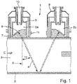
- FIG. 1 shows an arrangement with a clamp-on ultrasonic flowmeter 1 in the installed state on a pipeline 2.
- a measurement medium 3 which ideally flows through the pipeline 2 in the flow direction S.
- the schematically illustrated clamp-on ultrasonic flowmeter 1 preferably consists of two ultrasonic transducers 5a and 5b which are placed on the measuring tube from the outside and are connected to the pipeline 2 in a detachable or non-detachable manner.
- the variant shown is a so-called two-traverse arrangement, but other arrangements, such as a one-traverse arrangement, are also conceivable.
- the ultrasonic transducer 5a shown is attached to the pipeline 2 by means of a holding element 11 for fixing the ultrasonic transducer 5a.
- the holding element 11 and the ultrasonic transducer 5a are part of an ultrasonic transducer arrangement.
- the ultrasonic transducer 5a has a housing 9 which can be connected to the holding element 11, for example can be clamped or latched.
- a corresponding ultrasonic transducer 5a has an electromechanical transducer element 6, e.g. a piezo element. This is connected to an evaluation unit (not shown) via an electrical connection, e.g. a cable. The corresponding connection is routed away from the electromechanical converter element 6 e.g. by a cylindrical cable guide 10 with a longitudinal axis perpendicular to the pipeline 2 .
- the ultrasonic transducer 5a also has a coupling body 7 between the electromechanical transducer element 6 and the pipeline 2, which comprises a bearing surface toward the measuring tube and has a surface tilted relative to this bearing surface for arranging the electromechanical transducer element 6.
- the clamp-on ultrasonic flow meter in particular the electromechanical transducer element 6 of the ultrasonic transducer 5a, emits an ultrasonic signal with a dominant transmission frequency f ex to determine a flow rate or a flow rate during the measurement, which is received by the ultrasonic transducer 5b.
- the measurement is based on the transit time difference principle. Therefore, ultrasonic signals are transmitted and received obliquely in and obliquely against the direction of flow S.
- a transfer function of the at least one ultrasonic transducer used in the clamp-on flowmeter is determined.
- the transmission function of the ultrasonic transducer within the meaning of the present invention corresponds to the frequency-dependent directional characteristic of the ultrasonic transducer. This includes, among other things, the frequency- and angle-dependent amplitude of the wave propagation/radiation at a certain temperature.
- the angle dependency refers to the angle of incidence of the ultrasonic signal in the pipe or pipeline.
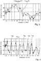
- the transfer function must be determined for each of these transducers. This feature is in 3 represented eg as a maximum normalized amplitude signal in decibels in relation to a frequency in MHz. All factors of the ultrasonic transducer influencing the ultrasonic signal, such as the material properties of the respective adaptation and coupling layers, the material properties of the exciting transducer element, such as a piezoceramic, and many other factors go into the function. The transfer function therefore does not change at a constant temperature, regardless of which tube the ultrasonic transducer is connected to.
- the transfer function of an ultrasonic transducer can thus be determined at the factory and stored in a data memory of an evaluation unit of the clamp-on ultrasonic flowmeter. Consequently, the transfer function can already be stored in the measuring device upon delivery. However, since the medium in the pipeline has a different temperature depending on the application, multiple transfer functions for multiple temperature ranges can also be stored.
- the clamp-on ultrasonic flow meter can independently select a corresponding transfer function for a temperature range or perform an approximation for the determined temperature between two transfer functions. Alternatively, the temperature can also be estimated, for example using the signal propagation time.
- the ultrasonic transducer transfer function can also be determined during the commissioning of the ultrasonic clamp-on device at the place of use of the measuring device. If the clamp-on flowmeter has two or more ultrasonic transducers, they can be held together. In this case, the sound coupling surfaces are preferably which the transducers rest on the pipe or pipeline, placed one on top of the other. If necessary, a centering adapter can be used.
- the evaluation unit uses a transmitted signal or pulse to determine a total transfer function of both ultrasonic converters.
- the amplitude spectrum of the received signal can be corrected by the excitation signal u ex (t).
- the received signal and the excitation signal can preferably be converted by Fourier transformation for the calculation.
- a received signal is detected in a method step. Two variants are distinguished.
- the received signal can be a conventional measurement signal, such as is received by an ultrasonic transducer in standard measurement operation.
- an ultrasonic transducer is used in transmission mode with an excitation signal u ex (t).
- the measurement signal as a reception signal, can be received by the same ultrasonic transducer that switches to reception mode after the transmission of the measurement signal.
- the measurement signal as a received signal, is received by another ultrasonic transducer in receive mode.
- the transducer element of an ultrasonic transducer eg a piezoelectric crystal, is excited with a certain excitation frequency f ex to emit a packet of sound waves. This spreads through the individual layers of the transducer, eg the so-called leading body, to a coupling surface which is in contact with the pipe.
- the sound wave packet enters the measurement medium as a measurement signal via the pipe wall, traverses this measurement medium, traverses the pipe wall a second time and is received by the additional ultrasonic transducer.
- a possible disruptive influence of the measurement medium in particular when measuring highly ultrasound-damping fluids, can also be ruled out using measurement technology. This is done by detecting the received signal u rec , structure- borne noise (t) using what is known as structure-borne noise measurement.
- structure-borne noise measurement This can be particularly preferred for a measurement with two ultrasonic transducers, for a 2-traverse measurement, as in 1 shown, are used, since the sound emitted by the first ultrasonic transducer propagates via the pipe wall directly to the second ultrasonic transducer, which is in reception mode. The sound is not influenced by the fluid because it is transmitted via the pipe wall.
- this received signal can advantageously be cleaned of the influence of the known excitation signal, preferably analogously to the previous method step.
- FIG. 3 shows an amplitude spectrum of the received signal as a solid line and an amplitude spectrum of the transfer function of two ultrasonic transducers as a dashed line.
- a transfer function is determined which is characteristic of the measuring point.
- the amplitude spectrum with a continuous line includes the influence of two ultrasonic transducers, the pipe wall and, depending on the variant, the influence of the fluid.
- the pipe wall resonances are characteristic of the material properties of the pipe. They can be used to correct measurement errors in ultrasonic flow measurement.
- the pipe wall resonance frequencies can also be used to determine changes at the measuring point, such as temperature influence, deposits, hydroabrasion and the like, on or in the pipe wall.
- the pipe wall resonance frequencies can be used to check whether the values known to the user for pipe wall thickness and pipe material are correct.
- the actual pipe wall thickness can also be calculated using the pipe wall resonance frequencies when using the entered material parameters.
- the pipe wall thickness is usually subject to a certain degree of uncertainty at the measuring point, since the customer is usually not able to measure the exact geometric dimension compared to the pipe outer diameter. This uncertainty goes directly into the calculation of the flow velocity and thus into the measurement error.
- the inside diameter of the pipe can be determined using the pipe wall resonance frequencies and the outside diameter of the pipe.
- Pipe wall properties within the meaning of the present invention include the transverse speed of sound and/or the longitudinal speed of sound.
- the pipe wall thickness can be determined when the fluid angle, fluid speed of sound and known pipe wall properties, in particular if the transversal speed of sound are known. With the outer diameter of the pipeline and the pipe wall thickness, an exact inner diameter of the pipeline can then be calculated at the measuring point for flow rate determination.
- the pipe wall properties can also be determined if the pipe wall thickness is known.
- the pipe wall properties can be used, for example, to check whether the specified pipe material is actually used by comparing setpoint values. The same applies to the pipe wall thickness, e.g. with progressive abrasion, by comparison with pipe wall resonance frequencies determined in the previous period.
- the proposed method could also be the basis of a new type of identification device that specifically determines pipe wall parameters by analyzing structure-borne noise.
- An exemplary structure consists of two angle probes, which can be mounted in a housing at a defined distance on the pipe on a straight line parallel to the pipe axis, analogous to a two-traverse arrangement of two ultrasonic transducers.
- a connected measuring transducer determines the pipe wall resonance frequencies based on the idea described above.
- the defined distance between the two transducers also allows the determination of the pipe wall material properties by evaluating the speed of sound via a transit time measurement.
- a possible procedure for determining the pipe wall material properties is to solve an inverse problem, as described for example in "Inversion of leaky Lamb wave data by simplex algorithm” by Karim, Mal and Bar-Cohen ( Journal of the Acoustical Society of America, Vol. 88, no. 1, 1990 ) is described for the examination of plates.
- the signals u rec,structure-borne noise ( t ) received directly via the pipe wall are evaluated and compared with model calculations.
- the parameters, in particular material properties, of the model are adjusted until the deviation between the signal calculated by the model and the received signal measured is minimal.
- the identification device can therefore be used to determine both the pipe wall thickness and the pipe wall properties.
- the multiplication/division of non-logarithmic values can also be used.
Landscapes
- Physics & Mathematics (AREA)
- General Physics & Mathematics (AREA)
- Fluid Mechanics (AREA)
- Electromagnetism (AREA)
- General Health & Medical Sciences (AREA)
- Health & Medical Sciences (AREA)
- Life Sciences & Earth Sciences (AREA)
- Chemical & Material Sciences (AREA)
- Analytical Chemistry (AREA)
- Biochemistry (AREA)
- Immunology (AREA)
- Pathology (AREA)
- Acoustics & Sound (AREA)
- Algebra (AREA)
- Mathematical Analysis (AREA)
- Mathematical Optimization (AREA)
- Mathematical Physics (AREA)
- Pure & Applied Mathematics (AREA)
- Engineering & Computer Science (AREA)
- Signal Processing (AREA)
- Measuring Volume Flow (AREA)
- Investigating Or Analyzing Materials By The Use Of Ultrasonic Waves (AREA)
Description
Die vorliegende Erfindung betrifft ein Verfahren zur Ermittlung zumindest einer Rohrwandresonanzfrequenz, sowie ein Clamp-On-Ultraschall-Durchflussmessgerät, ein Verfahren zur Ermittlung eines Durchflusses und/oder einer Durchflussgeschwindigkeit, ein Verfahren zur Ermittlung von Veränderungen einer Messstelle und ein Rohr-Identifikationsgerät.The present invention relates to a method for determining at least one pipe wall resonance frequency and a clamp-on ultrasonic flowmeter, a method for determining a flow rate and/or a flow rate, a method for determining changes in a measuring point and a pipe identification device.
Clamp-On-Ultraschall-Durchflussmessgeräte sind seit langem bekannt. Sie können nach dem Dopplerprinzip oder nach dem Laufzeitdifferenzprinzip betrieben werden. Üblicherweise werden die Ultraschallwandler, auch Ultraschall-Transducer genannt, der Clamp-On-Ultraschall-Durchflussmessgeräte von außen an eine bestehende Rohrleitung aufgesetzt und festgeschnallt oder anderweitig an der Rohrleitung festgelegt. Eine Installation des Durchflussmessgerätes kann somit ohne Unterbrechung des Durchflusses in der Rohrleitung erfolgen.Clamp-on ultrasonic flowmeters have been known for a long time. They can be operated according to the Doppler principle or according to the transit time difference principle. The ultrasonic transducers, also called ultrasonic transducers, of the clamp-on ultrasonic flowmeters are usually placed on an existing pipeline from the outside and strapped or otherwise fixed to the pipeline. The flow meter can thus be installed without interrupting the flow in the pipeline.
Die
Eine wesentliche Messunsicherheit bei Clamp-On Durchflussmessgeräten ist jedoch die Rohrleitung und deren unbekannte Parameter. So ist der Innendurchmesser der Rohrleitung nur als Durchschnittswert bekannt, er kann jedoch an der Messstelle erheblich vom Durchschnitt abweichen.However, a significant measurement uncertainty with clamp-on flowmeters is the pipeline and its unknown parameters. The inner diameter of the pipeline is only known as an average value, but it can deviate significantly from the average at the measuring point.
Durch
Auch die schalldämpfenden Eigenschaften der unterschiedlichen Wandungsmaterialien der Rohrleitung, sowie Innenbelag oder Hydroabrasion können die Genauigkeit der Durchflussmessung beeinflussen. Bislang ist für diese messstellenspezifische Fehlerquelle keine geeignete Kompensation bekannt.The accuracy of the flow measurement can also be influenced by the sound-absorbing properties of the different wall materials in the pipeline, as well as the inner lining or hydroabrasion. So far no suitable compensation is known for this source of error specific to the measuring point.
Ausgehend von dieser Vorbetrachtung ist es nunmehr Aufgabe der vorliegenden Erfindung ein Verfahren bereitzustellen, um eine genauere Durchflussmessung, insbesondere für Clamp-On-Ultraschall-Durchflussmessgeräte, zu gewährleisten.Proceeding from this preliminary consideration, it is now the object of the present invention to provide a method to ensure a more precise flow measurement, in particular for clamp-on ultrasonic flow measuring devices.
Die vorliegende Erfindung löst diese Aufgabe durch ein Verfahren mit den Merkmalen des Anspruchs 1 oder 13.The present invention solves this problem by a method having the features of
Darüber hinaus ermöglicht die Erfindung das Bereitstellen eines geeigneten Clamp-On Durchflussmessgerätes und eines Rohrwand-Identifikationsgerät, mit welchem Rohrleitungsparameter ermittelbar sind.In addition, the invention makes it possible to provide a suitable clamp-on flowmeter and a pipe wall identification device with which pipeline parameters can be determined.
Es hat sich gezeigt, dass durch Ermittlung einer oder mehrerer Rohrwandresonanzfrequenzen eine Korrektur des gemessenen Durchflusses und/oder einer gemessenen Durchflussgeschwindigkeit erfolgen kann.It has been shown that by determining one or more pipe wall resonance frequencies, the measured flow rate and/or a measured flow rate can be corrected.
Ein erfindungsgemäßes Verfahren zur Ermittlung zumindest einer Rohrwandresonanzfrequenz f res einer Rohrleitung im Bereich einer Messstelle erfolgt mittels eines Feldgerätes der Prozessmesstechnik mit zumindest einem ersten Ultraschallwandler, welcher an der Messstelle an der Rohrleitung angebracht ist und umfasst die folgenden Schritte:
- Erfassen eines Empfangsspektrums U rec(f) aus einem Empfangssignal u rec(t) nach dem Aussenden eines Ultraschallsignals;
- Ermittlung einer zweiten Übertragungsfunktion aus einer ersten Übertragungsfunktion des ersten oder der mehreren Ultraschallwandler und dem Empfangsspektrum, wobei die zweite Übertragungsfunktion charakteristisch für die Messstelle ist; und
- Ermittlung der Rohrwandresonanzfrequenzen im Bereich der Messstelle durch Auswertung der Übertragungsfunktion.
- detecting a received spectrum U rec (f) from a received signal u rec (t) after the transmission of an ultrasonic signal;
- Determination of a second transfer function from a first transfer function of the first or more ultrasonic transducers and the reception spectrum, the second transfer function being characteristic of the measuring point; and
- Determination of the pipe wall resonance frequencies in the area of the measuring point by evaluating the transfer function.
Die vorgenannten Übertragungsfunktionen als auch das Empfangssignal können als Amplitudenspektren, z.B. Schallpegel in Dezibel als Funktion einer Frequenz, dargestellt werden.The aforementioned transfer functions and the received signal can be represented as amplitude spectra, e.g. sound level in decibels as a function of a frequency.
Die Übertragungsfunktion, die charakteristisch für die Messstelle ist, ist im Wesentlichen durch das Schallübertragungsverhalten der Rohrleitung bestimmt, einschließlich von anhaftendem Belag oder ähnlichem. In die Übertragungsfunktion kann allerdings auch im Fall von schalldämpfenden Medien das Übertragungsverhalten des Messmediums mit eingehen.The transmission function, which is characteristic of the measuring point, is mainly determined by the sound transmission behavior of the pipeline, including any deposits or similar. In the case of sound-damping media, however, the transfer behavior of the measuring medium can also be included in the transfer function.
Das Erfassen eines Empfangsspektrums U rec(f) aus einem Empfangssignal u rec(t) erfolgt nach dem Aussenden eines Ultraschallsignals. Dabei wird ein Zeitsignal u rec(t) gemessen und davon dann das komplexwertige Spektrum U rec(f) in Form einer Übertragungsfunktion berechnet.A received spectrum U rec (f) is detected from a received signal u rec (t) after the transmission of an ultrasonic signal. A time signal u rec (t) is measured and the complex-valued spectrum U rec (f) is then calculated from it in the form of a transfer function.
Die ermittelten Rohrwandresonanzfrequenzen können insbesondere, jedoch nicht ausschließlich, zur Korrektur eines ermittelten Durchflusses und/oder einer ermittelten Durchflussgeschwindigkeit genutzt werden und/oder zu anderen Auswertungen, z.B. zur Vorhersage einer günstigen Messstelle, zur Wartung und/oder Selbstkalibration des Ultraschall-Durchflussmessgerätes und dergleichen.The determined pipe wall resonance frequencies can be used in particular, but not exclusively, to correct a determined flow rate and/or a determined flow rate and/or for other evaluations, e.g. to predict a favorable measuring point, for maintenance and/or self-calibration of the ultrasonic flow meter and the like.
Vorteilhafte Ausgestaltungen der Erfindung sind Gegenstand der Unteransprüche.Advantageous configurations of the invention are the subject matter of the dependent claims.
Ein Bereitstellen der Übertragungsfunktion beschreibt vorteilhaft eine Änderung eines akustischen Pegels an einer Koppelfläche des ersten Ultraschallwandlers mit der Rohrleitung in Abhängigkeit zu einer bestimmten Frequenz der Eingangsspannung mit welcher ein schallerzeugendes Element des Ultraschallwandlers betrieben wirdProviding the transfer function advantageously describes a change in an acoustic level at a coupling surface of the first ultrasonic transducer with the pipeline as a function of a specific frequency of the input voltage with which a sound-generating element of the ultrasonic transducer is operated
Es ist von Vorteil, wenn das Feldgerät der Prozessmesstechnik zumindest einen Datenspeicher aufweist und die Übertragungsfunktion des ersten oder der mehreren Ultraschallwandler abrufbar auf dem Datenspeicher hinterlegt ist.It is advantageous if the field device for process measurement technology has at least one data memory and the transmission function of the first or the plurality of ultrasonic transducers is stored in the data memory so that it can be called up.
Es ist zudem von Vorteil, wenn ein Bereitstellen der Übertragungsfunktion von zwei Ultraschallwandlern durch Ermittlung einer Gesamtübertragungsfunktion erfolgt, indem die Ultraschallwandler an ihren Kopplungsflächen miteinander verbunden werden. Die Gesamtübertragungsfunktion beschreibt somit die Propagation des Schallsignals durch den ersten und den zweiten Ultraschallwandler.It is also advantageous if the transfer function of two ultrasonic transducers is provided by determining an overall transfer function by Ultrasonic transducers are connected to each other at their coupling surfaces. The overall transfer function thus describes the propagation of the sound signal through the first and the second ultrasonic transducer.
Dies kann entweder auf einem Datenspeicher hinterlegt werden oder aber vor Ort, also während der Installation als Teilschritt vor der Montage auf dem Rohr ermittelt, insbesondere gemessen, werden.This can either be stored on a data memory or determined, in particular measured, on site, ie during installation as a partial step prior to assembly on the pipe.
Zur Ermittlung des Empfangsspektrums kann vorteilhaft
- ein Aussenden eines Ultraschallsignals durch ein schallerzeugendes Element des ersten Ultraschallwandlers erfolgen,
- wobei das Signal zumindest durch den Ultraschallwandler, zumindest zweimal durch eine Rohrwandung der Rohrleitung, durch das Messmedium und ein zweites Mal durch den ersten oder durch einen zweiten Ultraschallwandler propagiert, und durch das schallerzeugende Element des ersten Ultraschallwandlers oder durch ein schallerzeugendes Element des zweiten Ultraschallwandlers als Empfangssignals empfangen und in ein Empfangsspektrum umgewandelt wird.
- an ultrasonic signal is emitted by a sound-generating element of the first ultrasonic transducer,
- wherein the signal propagates at least through the ultrasonic transducer, at least twice through a pipe wall of the pipeline, through the measurement medium and a second time through the first or through a second ultrasonic transducer, and through the sound-generating element of the first ultrasonic transducer or through a sound-generating element of the second ultrasonic transducer as Received signal is received and converted into a reception spectrum.
Alternativ oder zusätzlich kann das Ermitteln des Empfangsspektrums vorteilhaft durch
- ein Aussenden eines Ultraschallsignals durch ein schallerzeugendes Element des ersten Ultraschallwandlers erfolgen,
- wobei das Signal ausschließlich durch den Ultraschallwandler, durch eine Rohrwandung der Rohrleitung und durch einen zweiten Ultraschallwandler propagiert, und durch ein schallerzeugendes Element eines zweiten Ultraschallwandlers als Empfangssignals empfangen und in ein Empfangsspektrum umgewandelt wird.
- an ultrasonic signal is emitted by a sound-generating element of the first ultrasonic transducer,
- wherein the signal is propagated exclusively through the ultrasonic transducer, through a pipe wall of the pipeline and through a second ultrasonic transducer, and is received as a received signal by a sound-generating element of a second ultrasonic transducer and is converted into a received spectrum.
Die Ermittlung einer Übertragungsfunktion, die charakteristisch für die Messstelle ist, kann vorteilhaft durch Subtraktion der logarithmierten Amplitudenspektren der Übertragungsfunktion zumindest des ersten oder mehrerer im Bereich der Messstelle befindlichen Ultraschallwandler und des Empfangsspektrums erfolgen.A transfer function that is characteristic of the measuring point can advantageously be determined by subtracting the logarithmic amplitude spectra of the transfer function of at least the first or more ultrasonic transducers located in the area of the measuring point and the reception spectrum.
Es ist zudem von Vorteil, wenn die Ermittlung der Rohrwandresonanzfrequenzen im Bereich der Messstelle durch Ermittlung der Amplitudenmaxima des Amplitudenspektrums der Übertragungsfunktion erfolgt.It is also advantageous if the pipe wall resonance frequencies in the area of the measuring point are determined by determining the amplitude maxima of the amplitude spectrum of the transfer function.
Ein erfindungsgemäßes Clamp-On-Ultraschall-Durchflussmessgerät umfasst zumindest den ersten Ultraschallwandler und eine Auswerteeinheit, an welcher der erste Ultraschallwandler angeschlossen ist und welche ausgebildet ist das erfindungsgemäße Verfahrens zu betreiben.A clamp-on ultrasonic flowmeter according to the invention comprises at least the first ultrasonic converter and an evaluation unit to which the first ultrasonic converter is connected and which is designed to operate the method according to the invention.
Es ist von Vorteil, wenn die Auswerteeinheit ausgerüstet ist zum Ermittlung des Durchflusses und/oder der Durchflussgeschwindigkeit nach dem Laufzeitdifferenzverfahren.It is advantageous if the evaluation unit is equipped to determine the flow rate and/or the flow rate using the transit time difference method.
Es ist von Vorteil, wenn die Auswerteeinheit ausgerüstet ist, basierend auf der zumindest einen Rohrwandresonanzfrequenz ein Anregungssignal für den ersten Ultraschallwandler, vorzugsweise jedoch eine Frequenz des Anregungssignals, einzustellen.It is advantageous if the evaluation unit is equipped to set an excitation signal for the first ultrasonic transducer, but preferably a frequency of the excitation signal, based on the at least one pipe wall resonance frequency.
Weiterhin erfindungsgemäß ist ein Verfahren zur Ermittlung eines Durchflusses oder der Durchflussgeschwindigkeit durch ein Clamp-On-Ultraschall-Durchflussmessgerät, wobei Rohrwandresonanzfrequenzen bei der Ermittlung des Durchflusses berücksichtigt werden, und wobei die Rohrwandresonanzfrequenzen nach dem erfindungsgemäßen Verfahren ermittelt wurden.Also according to the invention is a method for determining a flow or the flow rate through a clamp-on ultrasonic flow meter, wherein Pipe wall resonance frequencies are taken into account when determining the flow, and the pipe wall resonance frequencies were determined using the method according to the invention.
Erfindungsgemäß ist zudem ein Verfahren zur Ermittlung von Veränderungen einer Messstelle, an welcher ein Clamp-On Durchflussmessgerät festgelegt ist, wobei eine Veränderung der Messstelle angezeigt wird, sofern die ermittelte Rohrwandresonanzfrequenz oder die Rohrwandresonanzfrequenzen einen Sollwert überschreiten, wobei die Rohrwandresonanzfrequenzen nach dem erfindungsgemäßen Verfahren ermittelt wurden.According to the invention is also a method for determining changes in a measuring point at which a clamp-on flow meter is fixed, with a change in the measuring point being displayed if the determined pipe wall resonance frequency or the pipe wall resonance frequencies exceed a setpoint, the pipe wall resonance frequencies being determined using the method according to the invention .
Ein erfindungsgemäßes Rohr-Identifikationsgerät zur Ermittlung von Rohrwandparametern, insbesondere der Rohrwanddicke und des Rohrwandmaterials, weist zumindest einen Ultraschallwandler auf und eine Auswerteeinheit, welche eingerichtet ist das erfindungsgemäße Verfahren auszuführen und aus den ermittelten Rohrwandresonanzfrequenzen die Rohrwandstärke und/oder das Rohrwandmaterial zu ermitteln.A pipe identification device according to the invention for determining pipe wall parameters, in particular the pipe wall thickness and the pipe wall material, has at least one ultrasonic transducer and an evaluation unit which is set up to carry out the method according to the invention and to determine the pipe wall thickness and/or the pipe wall material from the determined pipe wall resonance frequencies.
Nachfolgend wird die Erfindung anhand eines Ausführungsbeispiels und anhand der beigefügten Figuren näher erläutert. Es zeigen:
- Fig. 1
- schematische Darstellung eines sogenannten Clamp-On-Ultraschall-Durchflussmessgerätes;
- Fig. 2
- exemplarisches Diagramm einer frequenzabhängigen Messabweichung;
- Fig. 3
- Diagramm eines Amplitudenspektrums eines Empfangssignals und einer Übertragungsfunktion eines ausgewählten Ultraschallwandlers; und
- Fig. 4
- ermittelte Übertragungsfunktion der Rohrwand und daraus ermittelte Rohrwandresonanzfrequenzen.
- 1
- schematic representation of a so-called clamp-on ultrasonic flow meter;
- 2
- exemplary diagram of a frequency-dependent measurement error;
- 3
- Diagram of an amplitude spectrum of a received signal and a transfer function of a selected ultrasonic transducer; and
- 4
- determined transfer function of the pipe wall and pipe wall resonance frequencies determined from it.
Clamp-On-Ultraschall-Durchflussmessgeräte sind an sich bekannt. Diese Messgeräte können entweder die Durchflussbestimmung anhand des Laufzeitdifferenz-Prinzips ermittelt werden oder nach dem Doppler-Prinzip ermittelt werden. Die Bestimmung mittels des Doppler-Prinzips kann bereits mit einem Ultraschallwandler durchgeführt werden, beim Laufzeitdifferenz-Prinzip werden bekanntermaßen zumindest zwei Ultraschallwandler eingesetzt.Clamp-on ultrasonic flowmeters are known per se. These measuring devices can either determine the flow rate using the transit time difference principle or be determined using the Doppler principle. The determination by means of the Doppler principle can already be carried out with an ultrasonic transducer; in the case of the transit time difference principle, at least two ultrasonic transducers are used, as is known.
Bei der Durchflussmessung werden Anregungssignale mit einer gewissen Anregungsfrequenz erzeugt. Diese Anregungsfrequenz wird zumeist aus einem vorgegebenen Frequenzbereich durch das Durchflussmessgerät selbst bestimmt und liegt oftmals im Bereich der Mittenfrequenz der verwendeten Ultraschallwandler.When measuring flow, excitation signals are generated with a certain excitation frequency. This excitation frequency is usually determined from a predetermined frequency range by the flow meter itself and is often in the range of the center frequency of the ultrasonic transducer used.
Das schematisch dargestellte Clamp-On-Ultraschall-Durchflussmessgerät 1 besteht vorzugsweise aus zwei Ultraschallwandlern 5a und 5b welche von außen auf das Messrohr aufgesetzt sind und lösbar oder unlösbar mit der Rohrleitung 2 verbunden sind. In der dargestellten Variante handelt es sich um eine sogenannte Zwei-Traversen-Anordnung, es sind allerdings auch andere Anordnungen, so z.B. eine Ein-Traversen-Anordnung, denkbar.The schematically illustrated clamp-on
Der in
Ein entsprechender Ultraschallwandler 5a weist ein elektromechanisches Wandlerelement 6, z.B. ein Piezoelement, auf. Dieses ist über eine elektrische Verbindung, z.B. ein Kabel, mit einer nicht näher dargestellten Auswerteeinheit verbunden. Die entsprechende Verbindung ist dabei z.B. durch eine zylindrische Kabelführung 10 mit einer Längsachse senkrecht zur Rohrleitung 2 vom elektromechanischen Wandlerelement 6 weggeführt.A corresponding
Der Ultraschallwandler 5a weist zudem zwischen dem elektromechanischen Wandlerelement 6 und der Rohrleitung 2 einen Koppelkörper 7 auf, welcher eine Auflagefläche zum Messrohr hin umfasst und eine gegenüber dieser Auflagefläche gekippte Fläche zur Anordnung des elektromechanischen Wandlerelements 6 aufweist.The
Das Clamp-On-Ultraschall-Durchflussmessgerät, insbesondere das elektromechanische Wandlerelement 6 des Ultraschallwandlers 5a, sendet zur Ermittlung eines Durchflusses oder einer Durchflussgeschwindigkeit während der Messung ein Ultraschallsignal mit dominanter Sendefrequenz f ex aus, welches durch den Ultraschallwandler 5b empfangen wird.The clamp-on ultrasonic flow meter, in particular the
Die Messung erfolgt nach dem Laufzeitdifferenzprinzip. Daher werden Ultraschallsignale einmal schräg in und einmal schräg entgegen der Strömungsrichtung S ausgesandt und empfangen.The measurement is based on the transit time difference principle. Therefore, ultrasonic signals are transmitted and received obliquely in and obliquely against the direction of flow S.
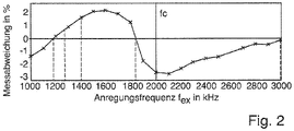
Bei der Wahl der Anregungsfrequenz f ex des elektromagnetischen Wandlerelements 6 ist es bekannt sich an der Mittenfrequenz des Wandlerelements 6 zu orientieren.When selecting the excitation frequency f ex of the
Es hat sich allerdings gezeigt, dass bei der Auswahl der Mittenfrequenz als Anregungsfrequenz nicht immer die optimale Wahl für den Betrieb eines Ultraschall-Durchflussmessgerätes ist.
Es hat sich gezeigt dass die Rohrwand der jeweiligen Rohrleitung einen Einfluss auf den Messfehler hat. Selbst bei Rohrwänden aus identischem Material kann der Messfehler je nach Rohrwandstärke variieren.It has been shown that the pipe wall of the respective pipeline has an influence on the measurement error. Even with tube walls made of identical material, the measurement error can vary depending on the tube wall thickness.
Es ist daher wichtig Kenntnisse über die genaue Rohrwandstärke, als auch über die Materialeigenschaften der Rohrleitung, zu gewinnen, auf welche das Clamp-On-Ultraschall-Durchflussmessgerät angebracht ist. Dabei sind mechanische Biegemoden der Rohrwandung, auch Rayleigh-Lamb-Wellen genannt, von Bedeutung. Eine möglichst gute Wahl des elektrischen Anregungssignals kann zu einer Messung mit geringen Abweichungen führen. Hierfür werden jedoch Kenntnisse der nächstgelegenen Rohrwandresonanzfrequenzen f res benötigt.It is therefore important to gain knowledge of the exact pipe wall thickness as well as the material properties of the pipeline to which the clamp-on ultrasonic flow meter is fitted. Mechanical bending modes of the pipe wall, also known as Rayleigh-Lamb waves, are important here. Choosing the best possible electrical excitation signal can lead to a measurement with small deviations. However, this requires knowledge of the nearest pipe wall resonance frequencies f res .
Diese Rohrwandresonanzfrequenzen, also diese mechanische Moden, können im Rahmen der vorliegenden Erfindung messtechnisch ermittelt werden.These pipe wall resonance frequencies, ie these mechanical modes, can be determined by measurement within the scope of the present invention.
Das Verfahren zum Ermitteln zumindest einer Rohrwandübertragungsfrequenz umfasst folgende Schritte:
- Ermittlung eines Empfangsspektrums U rec(f) aus einem Empfangssignal u rec(t) nach dem Aussenden eines Ultraschallsignals u ex(t) mit Anregungsfrequenz f ex;
- Ermittlung einer Übertragungsfunktion, welche charakteristisch für die Messstelle ist; und
- Ermittlung der zumindest einen Rohrwandresonanzfrequenz oder mehrerer Rohrwandresonanzfrequenzen.
- Determination of a received spectrum U rec (f) from a received signal u rec (t) after the transmission of an ultrasonic signal u ex (t) with excitation frequency f ex ;
- Determination of a transfer function which is characteristic of the measuring point; and
- Determining the at least one pipe wall resonance frequency or several pipe wall resonance frequencies.
In einem vorhergehenden Verfahrensschritt erfolgt die Ermittlung einer Übertragungsfunktion des zumindest einen im Clamp-On-Durchflussmessgerätes eingesetzten Ultraschallwandlers. Die Übertragungsfunktion des Ultraschallwandlers im Sinne der vorliegenden Erfindung entspricht der frequenzabhängigen Richtcharakteristik des Ultraschallwandlers. Diese umfasst u.a. die frequenz- und winkelabhängige Amplitude der Wellenausbreitung/-abstrahlung bei einer gewissen Temperatur. Die Winkelabhängigkeit bezieht sich auf den Einfallwinkel des Ultraschallsignals ins Rohr bzw. in die Rohrleitung.In a preceding method step, a transfer function of the at least one ultrasonic transducer used in the clamp-on flowmeter is determined. The transmission function of the ultrasonic transducer within the meaning of the present invention corresponds to the frequency-dependent directional characteristic of the ultrasonic transducer. This includes, among other things, the frequency- and angle-dependent amplitude of the wave propagation/radiation at a certain temperature. The angle dependency refers to the angle of incidence of the ultrasonic signal in the pipe or pipeline.
Es versteht sich, dass bei mehreren Ultraschallwandlern für jeden dieser Wandler die Übertragungsfunktion ermittelt werden muss. Diese Funktion ist in
Somit kann die Übertragungsfunktion eines Ultraschallwandlers werksseitig bestimmt werden und in einem Datenspeicher einer Auswerteeinheit des Clamp-On-Ultraschall-Durchflussmessgerätes hinterlegt werden. Folglich kann die Übertragungsfunktion bereits bei Auslieferung im Messgerät hinterlegt sein. Da allerdings das Medium in der Rohrleitung je nach Anwendung eine unterschiedliche Temperatur aufweist, können auch mehrere Übertragungsfunktionen für mehrere Temperaturbereiche hinterlegt sein. Durch Ermittlung der Temperatur, beispielsweise durch einen im Ultraschallwandler integrierten Temperatursensor, kann das Clamp-On-Ultraschall-Durchflussmessgerät eine entsprechende Übertragungsfunktion für einen Temperaturbereich selbstständig auswählen oder zwischen zwei Übertragungsfunktionen eine Approximation für die ermittelten Temperatur durchführen. Alternativ kann die Temperatur auch geschätzt werden, beispielsweise anhand der Signallaufzeit.The transfer function of an ultrasonic transducer can thus be determined at the factory and stored in a data memory of an evaluation unit of the clamp-on ultrasonic flowmeter. Consequently, the transfer function can already be stored in the measuring device upon delivery. However, since the medium in the pipeline has a different temperature depending on the application, multiple transfer functions for multiple temperature ranges can also be stored. By determining the temperature, for example using a temperature sensor integrated in the ultrasonic converter, the clamp-on ultrasonic flow meter can independently select a corresponding transfer function for a temperature range or perform an approximation for the determined temperature between two transfer functions. Alternatively, the temperature can also be estimated, for example using the signal propagation time.
Alternativ kann die Ermittlung der Ultraschallwandler-Übertragungsfunktion auch während der Inbetriebnahme des Ultraschall-Clamp-On Gerätes am Einsatzort des Messgerätes erfolgen. Sofern das Clamp-On Durchflussmessgerät zwei oder mehr Ultraschallwandler aufweist, so können diese aneinandergehalten werden. Dabei werden vorzugsweise die Schalleinkopplungsflächen, mit welchen die Wandler auf dem Rohr bzw. der Rohrleitung aufliegen, aufeinander gelegt. Gegebenenfalls kann ein Zentrieradapter genutzt werden. Die Auswerteeinheit ermittelt anhand eines ausgesandten Signals bzw. Pulses eine Gesamtübertragungsfunktion beider Ultraschallwandler.Alternatively, the ultrasonic transducer transfer function can also be determined during the commissioning of the ultrasonic clamp-on device at the place of use of the measuring device. If the clamp-on flowmeter has two or more ultrasonic transducers, they can be held together. In this case, the sound coupling surfaces are preferably which the transducers rest on the pipe or pipeline, placed one on top of the other. If necessary, a centering adapter can be used. The evaluation unit uses a transmitted signal or pulse to determine a total transfer function of both ultrasonic converters.
Bei einer Messung nach dem Laufzeitdifferenzverfahren mit zwei Ultraschallwandlern müssen im Grunde die logarithmierten Einzelübertragungsfunktionen beider Ultraschallwandler addiert werden. Dieser Schritt der Einzeladdition kann bei Ermittlung der Gesamtfunktion beider Ultraschallwandler vorteilhaft entfallen.In the case of a measurement using the transit time difference method with two ultrasonic transducers, the logarithmic individual transfer functions of both ultrasonic transducers must basically be added. This step of individual addition can advantageously be omitted when determining the overall function of both ultrasonic transducers.
In beiden Fällen, also der werksseitigen Ermittlung als auch der Ermittlung vor Ort, kann besonders bevorzugt eine Korrektur des Amplitudenspektrums des Empfangssignals durch das Anregungssignal u ex(t) erfolgen. Das Empfangssignal und das Anregungssignal können bevorzugt durch Fourier-Transformation zur Berechnung umgewandelt werden. Durch Subtraktion der logarithmierten Amplitudenspektren, also dem Anregungsspektrum und dem Empfangsspektrum, erhält man das vom Anregungssignal bereinigte Empfangsspektrum, welches der Übertragungsfunktion entspricht.In both cases, ie the determination at the factory and also the determination on site, the amplitude spectrum of the received signal can be corrected by the excitation signal u ex (t). The received signal and the excitation signal can preferably be converted by Fourier transformation for the calculation. By subtracting the logarithmic amplitude spectra, i.e. the excitation spectrum and the received spectrum, the received spectrum, which has been cleaned of the excitation signal and corresponds to the transfer function, is obtained.
In einem Verfahrensschritt erfolgt das Erfassen eines Empfangssignals. Dabei werden zwei Varianten unterschieden.A received signal is detected in a method step. Two variants are distinguished.
In einer ersten Variante kann es sich bei dem Empfangssignal um ein herkömmliches Messsignal handeln, wie es im Standard-Messbetrieb von einem Ultraschallwandler empfangen wird. Dabei wird von einem Ultraschallwandler im Sendemodus mit einem Anregungssignal u ex(t) angeregt.In a first variant, the received signal can be a conventional measurement signal, such as is received by an ultrasonic transducer in standard measurement operation. In this case, an ultrasonic transducer is used in transmission mode with an excitation signal u ex (t).
Sofern die Durchflussmessung nach dem Dopplerprinzip erfolgt, so kann das Messsignal, als Empfangssignal, von dem gleichen Ultraschallwandler empfangen werden, welcher nach dem Aussenden des Messsignals in den Empfangsmodus umschaltet.If the flow rate is measured according to the Doppler principle, the measurement signal, as a reception signal, can be received by the same ultrasonic transducer that switches to reception mode after the transmission of the measurement signal.
Sofern das Laufzeitdifferenz-Prinzip genutzt wird, so wird das Messsignal, als Empfangssignal, durch einen weiteren Ultraschallwandler im Empfangsmodus empfangen. Das Wandlerelement eines Ultraschallwandlers, z.B. ein Piezokristall, wird dabei mit einer gewissen Anregungsfrequenz f ex zum Aussenden eines Schallwellenpakets angeregt. Dieses breitet sich durch die einzelnen Schichten des Wandlers, z.B. den sogenannten Vorlaufkörper, bis zu einer Einkoppelfläche aus, welche am Rohr anliegt. An dieser Stelle tritt das Schallwellenpaket als Messsignal über die Rohrwandung in das Messmedium ein, durchquert dieses Messmedium, durchquert die Rohrwandung ein zweites Mal und wird von dem weiteren Ultraschallwandler empfangen. Aus der Betrachtung dieses Signalpfads wird klar, dass das Messsignal und somit auch die damit verbundenen Messfehler von dem Einfluss der beiden Ultraschallwandler, der Rohrwandung und des Fluids bestimmt werden. Sofern es sich nicht um stark dämpfende Messmedien, wie z.B. Öl, handelt, kann jedoch der Einfluss des Messmediums vernachlässigt werden.If the transit time difference principle is used, the measurement signal, as a received signal, is received by another ultrasonic transducer in receive mode. The transducer element of an ultrasonic transducer, eg a piezoelectric crystal, is excited with a certain excitation frequency f ex to emit a packet of sound waves. This spreads through the individual layers of the transducer, eg the so-called leading body, to a coupling surface which is in contact with the pipe. At this point, the sound wave packet enters the measurement medium as a measurement signal via the pipe wall, traverses this measurement medium, traverses the pipe wall a second time and is received by the additional ultrasonic transducer. Looking at this signal path, it becomes clear that the measurement signal and thus also the associated measurement errors are determined by the influence of the two ultrasonic transducers, the pipe wall and the fluid. As long as the media to be measured are not heavily damping, such as oil, the influence of the medium can be neglected.
Alternativ kann in einer zweiten Variante des Erfassens eines Empfangssignals II auch ein möglicher störender Einfluss des Messmediums, insbesondere bei der Messung stark ultraschall-dämpfender Fluide, messtechnisch ausgeschlossen werden. Dies erfolgt, indem das Empfangssignal u rec, Körperschall(t) über eine sogenannte Körperschallmessung erfasst wird. Dies kann besonders bevorzugt bei einer Messung mit zwei Ultraschallwandlern, bei einer 2-Traversen-Messung, wie in
Bei beiden vorgenannten Varianten des Erfassens eines Empfangssignals kann dieses Empfangssignal von dem Einfluss des bekannten Anregungssignals, vorzugsweise analog zum vorhergehenden Verfahrensschritt, vorteilhaft bereinigt werden.In the two aforementioned variants of detecting a received signal, this received signal can advantageously be cleaned of the influence of the known excitation signal, preferably analogously to the previous method step.
Es folgt in einem weiteren Verfahrensschritt ein Ermitteln einer Übertragungsfunktion, welche charakteristisch für die Messstelle ist. Dies umfasst zumindest eine Rohrwandübertragungsfunktion, also ein akustisches Spektrum der Amplituden über der Frequenz. Gegebenenfalls kann, insbesondere bei stark schalldämpfenden Medien, auch die Übertragungsfunktion des Messmediums bei der Ermittlung der Übertragungsfunktion, welche charakteristisch für die Messstelle ist, berücksichtigt werden.In a further method step, a transfer function is determined which is characteristic of the measuring point. This includes at least one pipe wall transfer function, i.e. an acoustic spectrum of the amplitudes over the frequency. If necessary, particularly in the case of strongly sound-damping media, the transfer function of the measuring medium can also be taken into account when determining the transfer function which is characteristic of the measuring point.
Das Amplitudenspektrum mit durchgehender Linie beinhaltet den Einfluss zweier Ultraschallwandler, der Rohrwand und je nach Variante auch den Einfluss des Fluids.The amplitude spectrum with a continuous line includes the influence of two ultrasonic transducers, the pipe wall and, depending on the variant, the influence of the fluid.
Durch einfache Subtraktion der logarithmierten Spektren erhält man das Übertragungsverhalten des Systems, abzüglich des Einflusses durch das Anregungssignal und der Ultraschallwandler, also die Rohrwandübertragungsfunktion, in welcher ggf. auch die Übertragungsfunktion des Fluids mit eingeht. Dies ist allerdings nur bei der ersten Variante des Erfassens des Empfangssignals der Fall: ![]()
- wobei |U rec(f)| der komplexwertigen Fouriertransformierten eines Empfangssignal u rec(t) entspricht, welches Empfangssignal über eine Körperschallübertragung durch das Rohr oder über einen Fluidpfad mit n Traversen erfasst wurde, wobei n eine ganze Zahl ist;
- wobei |U Wandler(f)| den Amplituden der genannten frequenz- und winkelabhängigen Richtcharakteristik, für den je Frequenz dominanten Winkel oder Abstrahlwinkel jeweils eines Wandlers, entspricht und
- wobei |U ex(f)| dem Amplitudenspektrum des Anregungssignals uex(t) entspricht und
- wobei |U Messstelle(f)| dem Einfluss der Rohrwand oder dem Einfluss aus Rohrwand und Fluiddämpfung entspricht.
- where | U rec ( f )| corresponds to the complex-valued Fourier transform of a received signal u rec (t), which received signal was detected via a structure-borne noise transmission through the pipe or via a fluid path with n traverses, where n is an integer;
- where | U converter ( f )| corresponds to the amplitudes of said frequency- and angle-dependent directional characteristics for the dominant angle or beam angle of a converter for each frequency, and
- where | U ex ( f )| corresponds to the amplitude spectrum of the excitation signal u ex (t) and
- where | U measuring point ( f )| corresponds to the influence of the pipe wall or the influence of pipe wall and fluid damping.
Die Durchführung dieser Berechnung ermöglicht zusätzlich die Bestimmung von Fluid-Eigenschaften anhand der frequenzabhängigen Dämpfung. Die Stärke dieser Dämpfung ist bei hochviskosen Fluiden (z. B. Öle) charakteristisch und legt die Bestimmung der dynamischen Viskosität nahe. Weißt das Fluid keine starke frequenzabhängige Dämpfung auf (z. B. Wasser), dann entspricht bei beiden Varianten das berechnete Spektrum der Messstelle der Rohrwandübertragungsfunktion |U Rohrwand(f)|.Carrying out this calculation also enables the determination of fluid properties based on the frequency-dependent damping. The strength of this damping is characteristic of highly viscous fluids (e.g. oils) and suggests the determination of the dynamic viscosity. If the fluid does not show any strong frequency-dependent damping (e.g. water), then the calculated spectrum of the measuring point corresponds to the pipe wall transfer function | for both variants U tube wall ( f )|.
Dies gilt auch bei stark dämpfenden Fluiden, sofern die Fluiddämpfung monoton steigend/oder fallend ist, was bei Flüssigkeiten zumeist der Fall ist.This also applies to strongly damping fluids if the fluid damping is monotonously increasing/or decreasing, which is usually the case with liquids.
Nachfolgend werden Anwendungsfälle näher erörtert, in welchen die nach dem erfindungsgemäßen Verfahren ermittelten Rohrwandresonanzfrequenzen eingesetzt werden können.Applications are discussed in more detail below in which the pipe wall resonance frequencies determined using the method according to the invention can be used.
Die Rohrwandresonanzen sind charakteristisch für die Materialeigenschaften der Rohrleitung. Sie können zur Messfehlerkorrektur bei der Ultraschall-Durchflussmessung eingesetzt werden.The pipe wall resonances are characteristic of the material properties of the pipe. They can be used to correct measurement errors in ultrasonic flow measurement.
Die Rohrwandresonanzfrequenzen können auch genutzt werden um Veränderungen an der Messstelle, wie z.B. Temperatureinfluss, Ablagerungen, Hydroabrasion und dergleichen, an oder in der Rohrwandung festzustellen.The pipe wall resonance frequencies can also be used to determine changes at the measuring point, such as temperature influence, deposits, hydroabrasion and the like, on or in the pipe wall.
Zudem kann anhand der Rohrwandresonanzfrequenzen eine Überprüfung erfolgen, ob die dem Benutzer bekannten Werte für Rohrwandstärke und Rohrmaterial zutreffend sind. Ebenso kann anhand der Rohrwandresonanzfrequenzen die Berechnung der tatsächlichen Rohrwandstärke, bei Verwendung der eingegebenen Materialparameter, erfolgen.In addition, the pipe wall resonance frequencies can be used to check whether the values known to the user for pipe wall thickness and pipe material are correct. The actual pipe wall thickness can also be calculated using the pipe wall resonance frequencies when using the entered material parameters.
Die Rohrwandstärke unterliegt an der Messstelle meist einer gewissen Unsicherheit, da dem Kunden die Messung der genauen geometrischen Abmessung im Vergleich zum Rohraußendurchmesser in der Regel nicht möglich ist. Diese Unsicherheit geht direkt in die Berechnung der Strömungsgeschwindigkeit und damit in den Messfehler ein. Anhand der Rohrwandresonanzfrequenzen und des Rohraußendurchmessers kann der Rohrinnendurchmesser ermittelt werden.The pipe wall thickness is usually subject to a certain degree of uncertainty at the measuring point, since the customer is usually not able to measure the exact geometric dimension compared to the pipe outer diameter. This uncertainty goes directly into the calculation of the flow velocity and thus into the measurement error. The inside diameter of the pipe can be determined using the pipe wall resonance frequencies and the outside diameter of the pipe.
Es gilt gemäß der Veröffentlichung "Study of Lamb waves based upon the frequency and angular derivatives of the phase of the reflection coefficient" von Lenoir (![]()
![]()
Rohrwandeigenschaften im Sinne der vorliegenden Erfindung sind u.a. die transversale Schallgeschwindigkeit und/oder die longitudinale Schallgeschwindigkeit.Pipe wall properties within the meaning of the present invention include the transverse speed of sound and/or the longitudinal speed of sound.
Durch Umstellen der Gleichung nach d w kann bei bekanntem Fluid-Winkel, Fluid-Schallgeschwindigkeit und bei bekannten Rohrwandeigenschaften, insbesondere bei bekannter transversaler Schallgeschwindigkeit, die Rohrwandstärke bestimmt werden. Mit dem Außendurchmesser der Rohrleitung und der Rohrwandstärke kann sodann ein exakter Innendurchmesser der Rohrleitung an der Messstelle zur Durchflussermittlung berechnet werden.By rearranging the equation according to d w , the pipe wall thickness can be determined when the fluid angle, fluid speed of sound and known pipe wall properties, in particular if the transversal speed of sound are known. With the outer diameter of the pipeline and the pipe wall thickness, an exact inner diameter of the pipeline can then be calculated at the measuring point for flow rate determination.
Alternativ können auch die Rohrwandeigenschaften bei bekannter Rohrwandstärke ermittelt werden.Alternatively, the pipe wall properties can also be determined if the pipe wall thickness is known.
Aus den Rohrwandeigenschaften kann z.B. anhand durch Sollwertvergleich überprüft werden, ob es sich tatsächlich um das angegebene Rohrmaterial handelt. Gleiches gilt für die Rohrwandstärke, z.B. bei fortschreitender Abrasion, durch Vergleich mit zeitlich vorangegangenen ermittelten Rohrwandresonanzfrequenzen.The pipe wall properties can be used, for example, to check whether the specified pipe material is actually used by comparing setpoint values. The same applies to the pipe wall thickness, e.g. with progressive abrasion, by comparison with pipe wall resonance frequencies determined in the previous period.
Die vorgeschlagene Methode könnte auch Grundlage eines neuartigen Identifikationsgeräts sein, das durch Analyse von Körperschall zielgerichtet Rohrwandparameter ermittelt.The proposed method could also be the basis of a new type of identification device that specifically determines pipe wall parameters by analyzing structure-borne noise.
Dabei besteht ein beispielhafter Aufbau aus zwei Winkelprüfköpfen, die in einem Gehäuse in einem definierten Abstand, auf einer zur Rohrachse parallelen Geraden auf das Rohr montiert werden können, analog zu einer Zwei-Traversenanordnung zweier Ultraschallwandler.An exemplary structure consists of two angle probes, which can be mounted in a housing at a defined distance on the pipe on a straight line parallel to the pipe axis, analogous to a two-traverse arrangement of two ultrasonic transducers.
Wird dieses Gerät auf eine Rohrwand mit unbekannten Geometrie-/Materialeigenschaften aufgesetzt, so ermittelt ein daran angeschlossener Messumformer, basierend auf der oben beschriebenen Idee, die Rohrwand-Resonanzfrequenzen. Der definierte Abstand zwischen den beiden Wandlern erlaubt zusätzlich über eine Laufzeitmessung die Bestimmung der RohrwandMaterialeigenschaften durch Auswertung der Schallgeschwindigkeit.If this device is placed on a pipe wall with unknown geometry/material properties, a connected measuring transducer determines the pipe wall resonance frequencies based on the idea described above. The defined distance between the two transducers also allows the determination of the pipe wall material properties by evaluating the speed of sound via a transit time measurement.
Eine mögliche Vorgehensweise zur Bestimmung der Rohrwandmaterialeigenschaften besteht in der Lösung eines inversen Problems, wie es beispielsweise in "Inversion of leaky Lamb wave data by simplex algorithm" von Karim, Mal und Bar-Cohen (
Durch das Identifikationsgerät können daher sowohl die Rohrwandstärke als auch die Rohrwandeigenschaften ermittelt werden.The identification device can therefore be used to determine both the pipe wall thickness and the pipe wall properties.
Alternativ zur Addition/Subtraktion von logarithmierten Größen kann auch die Multiplikation/Division von nicht-logarithmierten Größen äquivalent verwendet werden.As an alternative to the addition/subtraction of logarithmic values, the multiplication/division of non-logarithmic values can also be used.
Claims (15)
- Procedure to determine at least a pipe wall resonance frequency of a pipe in the area of a measuring point using a field device used in process measuring technology with at least a first ultrasonic transducer, wherein said transducer is fixed on the pipe at the measuring point, wherein said procedure comprises the following steps:- Determination of a reception spectrum U rec(f) from a reception signal urec (t) following the emission of an ultrasonic signal;- Determination of a second transmission function UMeasuring point (f) from a first transmission function Utransducer (f) at least of the first or several of the ultrasonic transducers situated in the area of the measuring point and the reception spectrum Urec (f), wherein the second transmission function UMeasuring point (f) is characteristic for the measuring point; and- Determination of the at least one pipe wall resonance frequency fres, particularly of multiple resonance frequencies, in the area of the measuring point by evaluating the second transmission function UMeasuring point (f).
- Procedure as claimed in Claim 1, characterized in that the provision of the first transmission function Utransducer (f) comprises a frequency curve that is independent of the temperature and/or angle, wherein the angular independence refers to the angle of incidence of the ultrasonic signal of the ultrasonic transducer in the pipe.
- Procedure as claimed in Claim 1 or 2, characterized in that the field device used in process measuring technology comprises at least a data memory and wherein the first transmission function Utransducer (f) of the first or multiple ultrasonic transducers is saved in a retrievable manner on the data memory.
- Procedure as claimed in one of the previous claims, characterized in that several first transmission functions Utransducer (f) are provided for multiple temperatures or temperature ranges, and are particularly saved in a data memory.
- Procedure as claimed in one of the previous claims, characterized in that the transmission functions Utransducer (f) of two ultrasonic transducers are provided by determining a total transmission function, in that the ultrasonic transducers are connected to one another at their coupling surfaces, and are particularly pressed against one another.
- Procedure as claimed in one of the previous claims, characterized in that, in order to determine a reception spectrum Urec (f) from a reception signal urec (t), following the emission of an ultrasonic signal,an ultrasonic signal is emitted by a sound-generating element of the first ultrasonic transducer,wherein the signal propagates at least through the ultrasonic transducer, at least twice through a pipe wall, through the medium under measurement and a second time through the first or through a second ultrasonic transducer, and is received as a reception signal by the sound-generating element of the first ultrasonic transducer or by a sound-generating element of the second ultrasonic transducer and converted to a reception spectrum Urec (f).
- Procedure as claimed in one of the previous claims, characterized in that, in order to determine a reception spectrum Urec (f) from a reception signal urec (t), following the emission of an ultrasonic signal,an ultrasonic signal is transmitted by a sound-generating element of the first ultrasonic transducer,wherein the signal propagates exclusively through the ultrasonic transducer, through a pipe wall and through a second ultrasonic transducer, and is received as a reception signal by a sound-generating element of a second ultrasonic transducer and is converted to a reception spectrum Urec (f).
- Procedure as claimed in one of the previous claims, characterized in that the second transmission function UMeasuring point (f), which is characteristic of the measuring point, is determined by subtracting the logarithmic amplitude spectra of the first transmission function Utransducer (f) at least of the first or multiple ultrasonic transducers located in the area of the measuring point and of the reception spectrum Urec (f).
- Procedure as claimed in one of the previous claims, characterized in that the pipe wall resonance frequencies f res in the area of the measuring point is determined by determining the amplitude maxima of the amplitude spectrum of the second transmission function UMeasuring point (f).
- Clamp-on ultrasonic flowmeter comprising at least a first ultrasonic transducer and an evaluation unit to which the first ultrasonic transducer is connected and which is configured to execute the procedure as claimed in Claim 1.
- Clamp-on ultrasonic flowmeter as claimed in Claim 10, characterized in that the evaluation unit is designed to determine the flow and/or the flow velocity according to the transit time difference procedure.
- Clamp-on ultrasonic flowmeter as claimed in Claim 10 or 11, characterized in that the evaluation unit is equipped to set an excitation signal for the first ultrasonic transducer, particularly a frequency of the excitation signal, on the basis of the at least one pipe wall resonance frequency.
- Procedure designed to determine a flow or the flow velocity through a clamp-on ultrasonic flowmeter, characterized in that pipe wall resonance frequencies are taken into consideration in the determination of the flow, wherein the pipe wall resonance frequencies fres have been determined using the procedure as claimed in Claim 1.
- Procedure designed to determine changes to a measuring point to which a clamp-on ultrasonic flowmeter is attached, characterized in that a change in the measuring point is displayed as soon as the determined pipe wall resonance frequencies change over time in relation to the amplitude and/or the position in the spectrum (|U Measuring point(f)|) and exceed and/or drop below a target value, wherein the pipe wall resonance frequencies have been determined according to the procedure as claimed in Claim 1.
- Identification device for determining pipe wall parameters, preferably the pipe wall thickness dw and/or the pipe wall material properties, particularly the longitudinal and/or transversal sound velocity in the pipe wall material, characterized in that the identification unit has at least an ultrasonic transducer and an evaluation unit, which is designed to perform the procedure as claimed in Claim 1 and to determine the pipe wall thickness and/or the pipe wall material from the pipe wall resonance frequencies determined.
Applications Claiming Priority (2)
| Application Number | Priority Date | Filing Date | Title |
|---|---|---|---|
| DE102015107752.3A DE102015107752A1 (en) | 2015-05-18 | 2015-05-18 | Method for determining at least one tube wall resonance frequency and clamp-on ultrasonic flowmeter |
| PCT/EP2016/059308 WO2016184647A1 (en) | 2015-05-18 | 2016-04-26 | Method for determining a pipe wall resonant frequency, and clamp-on ultrasonic flowmeter |
Publications (2)
| Publication Number | Publication Date |
|---|---|
| EP3298359A1 EP3298359A1 (en) | 2018-03-28 |
| EP3298359B1 true EP3298359B1 (en) | 2022-06-22 |
Family
ID=55809129
Family Applications (1)
| Application Number | Title | Priority Date | Filing Date |
|---|---|---|---|
| EP16718683.2A Active EP3298359B1 (en) | 2015-05-18 | 2016-04-26 | Method for determining a pipe wall resonance frequency, and clamp-on-ultrasonic flowmeter |
Country Status (5)
| Country | Link |
|---|---|
| US (1) | US11435219B2 (en) |
| EP (1) | EP3298359B1 (en) |
| CN (1) | CN107636423B (en) |
| DE (1) | DE102015107752A1 (en) |
| WO (1) | WO2016184647A1 (en) |
Families Citing this family (9)
| Publication number | Priority date | Publication date | Assignee | Title |
|---|---|---|---|---|
| DE102015107752A1 (en) | 2015-05-18 | 2016-11-24 | Endress + Hauser Flowtec Ag | Method for determining at least one tube wall resonance frequency and clamp-on ultrasonic flowmeter |
| US10495499B2 (en) | 2017-10-27 | 2019-12-03 | METER Group, Inc. USA | Sonic anemometer |
| DE102017126916B4 (en) * | 2017-11-15 | 2020-03-12 | Samson Aktiengesellschaft | Process for encrypted communication in a process engineering plant, process engineering plant, field device and control electronics |
| EP3521774B1 (en) * | 2018-02-06 | 2020-04-01 | SICK Engineering GmbH | Ultrasound flow meter and method for determining the flow speed |
| DE102018003311B4 (en) * | 2018-04-24 | 2022-05-12 | Diehl Metering Gmbh | Method and measuring device for determining measurement information |
| ES2735648B2 (en) * | 2018-06-19 | 2020-05-20 | Sedal S L U | LIQUID MIXING DEVICE WITH ELECTRONIC CONTROL OF HIGH DYNAMICS OF REGULATION AND METHOD OF OPERATION OF THE SAME |
| EP3792656A1 (en) * | 2019-09-12 | 2021-03-17 | Continental Automotive GmbH | Method for elevation angle estimation based on an ultrasound sensor |
| EP4119906A1 (en) * | 2021-07-14 | 2023-01-18 | Georg Fischer Rohrleitungssysteme AG | Clamp-on ultrasound measuring device and method for its configuration |
| DE102021211941A1 (en) | 2021-10-22 | 2023-04-27 | Siemens Aktiengesellschaft | Calibration method for a flow measurement system, flow measurement system and computer program product |
Family Cites Families (23)
| Publication number | Priority date | Publication date | Assignee | Title |
|---|---|---|---|---|
| BE756811A (en) * | 1969-12-04 | 1971-03-01 | Ver Deutsche Metallwerke Ag | PROCESS FOR CHECKING THE INTERIOR DIAMETER OF TUBES |
| US4735097A (en) * | 1985-08-12 | 1988-04-05 | Panametrics, Inc. | Method and apparatus for measuring fluid characteristics using surface generated volumetric interrogation signals |
| US4930358A (en) * | 1987-03-27 | 1990-06-05 | Tokyo Keiki Co., Ltd. | Method of and apparatus for measuring flow velocity by using ultrasonic waves |
| JP2747618B2 (en) * | 1990-11-05 | 1998-05-06 | 株式会社トキメック | Ultrasonic flow velocity measuring method and apparatus |
| US5650571A (en) * | 1995-03-13 | 1997-07-22 | Freud; Paul J. | Low power signal processing and measurement apparatus |
| US6062091A (en) * | 1997-04-22 | 2000-05-16 | Baumoel; Joseph | Method and apparatus for determining ultrasonic pulse arrival in fluid using phase correlation |
| US6405603B1 (en) * | 2001-03-23 | 2002-06-18 | Joseph Baumoel | Method for determining relative amounts of constituents in a multiphase flow |
| US7328624B2 (en) * | 2002-01-23 | 2008-02-12 | Cidra Corporation | Probe for measuring parameters of a flowing fluid and/or multiphase mixture |
| US20040123666A1 (en) * | 2002-12-31 | 2004-07-01 | Ao Xiaolei S. | Ultrasonic damping material |
| CN1853098B (en) * | 2003-07-18 | 2010-12-08 | 罗斯蒙德公司 | Acoustic flowmeter and method for monitoring health degree of fixed equipment in industrial process |
| WO2005106530A1 (en) * | 2004-04-28 | 2005-11-10 | Matsushita Electric Industrial Co., Ltd. | Ultrasonic range finder |
| DE102004060065B4 (en) * | 2004-12-14 | 2016-10-20 | Robert Bosch Gmbh | Ultrasonic flow meter with guide elements |
| US8020428B2 (en) * | 2007-04-04 | 2011-09-20 | Colorado School Of Mines | System for and method of monitoring properties of a fluid flowing through a pipe |
| NO334481B1 (en) * | 2009-01-30 | 2014-03-17 | Statoilhydro Asa | Method and apparatus for measuring the thickness of a material deposit on an inner wall of a pipe structure |
| US8141434B2 (en) * | 2009-12-21 | 2012-03-27 | Tecom As | Flow measuring apparatus |
| WO2012031302A1 (en) * | 2010-09-03 | 2012-03-08 | Los Alamos National Security, Llc | Multiphase fluid characterization system |
| WO2012031305A1 (en) * | 2010-09-03 | 2012-03-08 | Los Alamos National Security, Llc | Method for noninvasive determination of acoustic properties of fluids inside pipes |
| EP2612143A4 (en) * | 2010-09-03 | 2017-01-18 | Los Alamos National Security LLC | Apparatus and method for noninvasive particle detection using doppler spectroscopy |
| EP2684011A4 (en) * | 2011-03-07 | 2015-09-30 | Los Alamos Nat Security Llc | Apparatus and method for acoustic monitoring of steam quality and flow |
| EP4235114A3 (en) * | 2012-08-22 | 2023-10-25 | Apator Miitors ApS | A compact ultrasonic flow meter |
| WO2015059990A1 (en) * | 2013-10-23 | 2015-04-30 | 富士電機株式会社 | Fluid metering device |
| US10908131B2 (en) * | 2015-04-02 | 2021-02-02 | Triad National Security, Llc | Acoustic gas volume fraction measurement in a multiphase flowing liquid |
| DE102015107752A1 (en) | 2015-05-18 | 2016-11-24 | Endress + Hauser Flowtec Ag | Method for determining at least one tube wall resonance frequency and clamp-on ultrasonic flowmeter |
-
2015
- 2015-05-18 DE DE102015107752.3A patent/DE102015107752A1/en active Pending
-
2016
- 2016-04-26 EP EP16718683.2A patent/EP3298359B1/en active Active
- 2016-04-26 WO PCT/EP2016/059308 patent/WO2016184647A1/en active Application Filing
- 2016-04-26 US US15/569,178 patent/US11435219B2/en active Active
- 2016-04-26 CN CN201680028001.4A patent/CN107636423B/en active Active
Also Published As
| Publication number | Publication date |
|---|---|
| US11435219B2 (en) | 2022-09-06 |
| CN107636423A (en) | 2018-01-26 |
| CN107636423B (en) | 2021-02-05 |
| WO2016184647A1 (en) | 2016-11-24 |
| DE102015107752A1 (en) | 2016-11-24 |
| EP3298359A1 (en) | 2018-03-28 |
| US20180149511A1 (en) | 2018-05-31 |
Similar Documents
| Publication | Publication Date | Title |
|---|---|---|
| EP3298359B1 (en) | Method for determining a pipe wall resonance frequency, and clamp-on-ultrasonic flowmeter | |
| EP3577427B1 (en) | Ultrasonic meter and method for sensing a flow variable | |
| EP3298360B1 (en) | Method, computer program product and apparatus for determining a characteristic parameter for evaluating a measuring device comprising a clamp-on ultrasonic flowmeter and a measuring pipe | |
| EP1931948B1 (en) | Device for determining or monitoring a medium volume or mass flow rate in a conduit | |
| DE102015107750A1 (en) | Measuring system for measuring at least one parameter of a fluid | |
| EP2656017B1 (en) | Coupling element of an ultrasonic transducer for an ultrasonic flow meter | |
| EP3521773B1 (en) | Ultrasound flow meter and method of determining a flow speed | |
| DE102016125537A1 (en) | Mass flow sensor according to the Coriolis principle and method for determining a mass flow | |
| DE102012022376A1 (en) | Method for determining pressure of fluid in container i.e. pipeline, of hydraulic system, involves determining flow velocity of fluid through container from measuring running time or measured Doppler shift of acoustic waves | |
| EP3486630A1 (en) | Measuring device for the determination of pressure in a measurement volume | |
| EP3940346A1 (en) | Flow meter and method for measuring the flow rate of a fluid | |
| EP3314210B1 (en) | Field device having a compensation circuit for eliminating environmental influences | |
| DE102017009462B4 (en) | Measuring device for determining a fluid variable | |
| EP3894799B1 (en) | Ultrasound transducer arrangement of a clamp-on ultrasound flow measuring unit, and a clamp-on ultrasound flow measuring unit and method for starting up the clamp-on ultrasound flow measuring unit | |
| EP1883791B1 (en) | Method for determining and monitoring a process parameter | |
| DE102011115691A1 (en) | Method for determination of viscosity of mineral oil, involves computing viscosity based on amplitude and frequency of ultrasonic signals and time period required for ultrasonic waves for passing through measuring section | |
| EP3268954B1 (en) | Arrangement and field device for process measurement technology | |
| EP3855134B1 (en) | Device for measuring the flow speed of a fluid | |
| EP2488844B1 (en) | Ultrasonic measuring device and measuring method | |
| EP3857185B1 (en) | Method and device for acoustical measurement in a pipe | |
| EP3248187B1 (en) | Method for producing a sound transducer for a field device in automation technology | |
| DE202020104105U1 (en) | Flow meter for measuring the flow of a fluid | |
| EP1731884B1 (en) | Layer thickness measuring method for an ultrasonic flow measuring channel | |
| EP0905487B1 (en) | Flowmeter | |
| DE102004027544B4 (en) | Method and device for determining the flow rate in an acoustically good transfer medium |
Legal Events
| Date | Code | Title | Description |
|---|---|---|---|
| STAA | Information on the status of an ep patent application or granted ep patent |
Free format text: STATUS: THE INTERNATIONAL PUBLICATION HAS BEEN MADE |
|
| PUAI | Public reference made under article 153(3) epc to a published international application that has entered the european phase |
Free format text: ORIGINAL CODE: 0009012 |
|
| STAA | Information on the status of an ep patent application or granted ep patent |
Free format text: STATUS: REQUEST FOR EXAMINATION WAS MADE |
|
| 17P | Request for examination filed |
Effective date: 20171010 |
|
| AK | Designated contracting states |
Kind code of ref document: A1 Designated state(s): AL AT BE BG CH CY CZ DE DK EE ES FI FR GB GR HR HU IE IS IT LI LT LU LV MC MK MT NL NO PL PT RO RS SE SI SK SM TR |
|
| AX | Request for extension of the european patent |
Extension state: BA ME |
|
| RIN1 | Information on inventor provided before grant (corrected) |
Inventor name: FROEHLICH, THOMAS Inventor name: BEZDEK, MICHAL Inventor name: RUPITSCH, STEFAN J. Inventor name: KISSLING, BEAT Inventor name: PLOSS, PETER |
|
| DAV | Request for validation of the european patent (deleted) | ||
| DAX | Request for extension of the european patent (deleted) | ||
| STAA | Information on the status of an ep patent application or granted ep patent |
Free format text: STATUS: EXAMINATION IS IN PROGRESS |
|
| 17Q | First examination report despatched |
Effective date: 20210608 |
|
| STAA | Information on the status of an ep patent application or granted ep patent |
Free format text: STATUS: EXAMINATION IS IN PROGRESS |
|
| REG | Reference to a national code |
Ref country code: DE Ref legal event code: R079 Ref document number: 502016014986 Country of ref document: DE Free format text: PREVIOUS MAIN CLASS: G01F0025000000 Ipc: G01F0001660000 |
|
| RIC1 | Information provided on ipc code assigned before grant |
Ipc: G01N 29/44 20060101ALI20220110BHEP Ipc: G01N 29/12 20060101ALI20220110BHEP Ipc: G01F 25/10 20220101ALI20220110BHEP Ipc: G01F 15/02 20060101ALI20220110BHEP Ipc: G01F 1/667 20220101ALI20220110BHEP Ipc: G01F 1/66 20060101AFI20220110BHEP |
|
| GRAP | Despatch of communication of intention to grant a patent |
Free format text: ORIGINAL CODE: EPIDOSNIGR1 |
|
| STAA | Information on the status of an ep patent application or granted ep patent |
Free format text: STATUS: GRANT OF PATENT IS INTENDED |
|
| INTG | Intention to grant announced |
Effective date: 20220218 |
|
| GRAS | Grant fee paid |
Free format text: ORIGINAL CODE: EPIDOSNIGR3 |
|
| GRAA | (expected) grant |
Free format text: ORIGINAL CODE: 0009210 |
|
| STAA | Information on the status of an ep patent application or granted ep patent |
Free format text: STATUS: THE PATENT HAS BEEN GRANTED |
|
| AK | Designated contracting states |
Kind code of ref document: B1 Designated state(s): AL AT BE BG CH CY CZ DE DK EE ES FI FR GB GR HR HU IE IS IT LI LT LU LV MC MK MT NL NO PL PT RO RS SE SI SK SM TR |
|
| REG | Reference to a national code |
Ref country code: GB Ref legal event code: FG4D Free format text: NOT ENGLISH |
|
| REG | Reference to a national code |
Ref country code: CH Ref legal event code: EP |
|
| REG | Reference to a national code |
Ref country code: DE Ref legal event code: R096 Ref document number: 502016014986 Country of ref document: DE |
|
| REG | Reference to a national code |
Ref country code: AT Ref legal event code: REF Ref document number: 1500039 Country of ref document: AT Kind code of ref document: T Effective date: 20220715 |
|
| REG | Reference to a national code |
Ref country code: IE Ref legal event code: FG4D Free format text: LANGUAGE OF EP DOCUMENT: GERMAN |
|
| REG | Reference to a national code |
Ref country code: NL Ref legal event code: FP |
|
| REG | Reference to a national code |
Ref country code: LT Ref legal event code: MG9D |
|
| PG25 | Lapsed in a contracting state [announced via postgrant information from national office to epo] |
Ref country code: SE Free format text: LAPSE BECAUSE OF FAILURE TO SUBMIT A TRANSLATION OF THE DESCRIPTION OR TO PAY THE FEE WITHIN THE PRESCRIBED TIME-LIMIT Effective date: 20220622 Ref country code: NO Free format text: LAPSE BECAUSE OF FAILURE TO SUBMIT A TRANSLATION OF THE DESCRIPTION OR TO PAY THE FEE WITHIN THE PRESCRIBED TIME-LIMIT Effective date: 20220922 Ref country code: LT Free format text: LAPSE BECAUSE OF FAILURE TO SUBMIT A TRANSLATION OF THE DESCRIPTION OR TO PAY THE FEE WITHIN THE PRESCRIBED TIME-LIMIT Effective date: 20220622 Ref country code: HR Free format text: LAPSE BECAUSE OF FAILURE TO SUBMIT A TRANSLATION OF THE DESCRIPTION OR TO PAY THE FEE WITHIN THE PRESCRIBED TIME-LIMIT Effective date: 20220622 Ref country code: GR Free format text: LAPSE BECAUSE OF FAILURE TO SUBMIT A TRANSLATION OF THE DESCRIPTION OR TO PAY THE FEE WITHIN THE PRESCRIBED TIME-LIMIT Effective date: 20220923 Ref country code: FI Free format text: LAPSE BECAUSE OF FAILURE TO SUBMIT A TRANSLATION OF THE DESCRIPTION OR TO PAY THE FEE WITHIN THE PRESCRIBED TIME-LIMIT Effective date: 20220622 Ref country code: BG Free format text: LAPSE BECAUSE OF FAILURE TO SUBMIT A TRANSLATION OF THE DESCRIPTION OR TO PAY THE FEE WITHIN THE PRESCRIBED TIME-LIMIT Effective date: 20220922 |
|
| PG25 | Lapsed in a contracting state [announced via postgrant information from national office to epo] |
Ref country code: RS Free format text: LAPSE BECAUSE OF FAILURE TO SUBMIT A TRANSLATION OF THE DESCRIPTION OR TO PAY THE FEE WITHIN THE PRESCRIBED TIME-LIMIT Effective date: 20220622 Ref country code: LV Free format text: LAPSE BECAUSE OF FAILURE TO SUBMIT A TRANSLATION OF THE DESCRIPTION OR TO PAY THE FEE WITHIN THE PRESCRIBED TIME-LIMIT Effective date: 20220622 |
|
| PG25 | Lapsed in a contracting state [announced via postgrant information from national office to epo] |
Ref country code: SM Free format text: LAPSE BECAUSE OF FAILURE TO SUBMIT A TRANSLATION OF THE DESCRIPTION OR TO PAY THE FEE WITHIN THE PRESCRIBED TIME-LIMIT Effective date: 20220622 Ref country code: SK Free format text: LAPSE BECAUSE OF FAILURE TO SUBMIT A TRANSLATION OF THE DESCRIPTION OR TO PAY THE FEE WITHIN THE PRESCRIBED TIME-LIMIT Effective date: 20220622 Ref country code: RO Free format text: LAPSE BECAUSE OF FAILURE TO SUBMIT A TRANSLATION OF THE DESCRIPTION OR TO PAY THE FEE WITHIN THE PRESCRIBED TIME-LIMIT Effective date: 20220622 Ref country code: PT Free format text: LAPSE BECAUSE OF FAILURE TO SUBMIT A TRANSLATION OF THE DESCRIPTION OR TO PAY THE FEE WITHIN THE PRESCRIBED TIME-LIMIT Effective date: 20221024 Ref country code: ES Free format text: LAPSE BECAUSE OF FAILURE TO SUBMIT A TRANSLATION OF THE DESCRIPTION OR TO PAY THE FEE WITHIN THE PRESCRIBED TIME-LIMIT Effective date: 20220622 Ref country code: EE Free format text: LAPSE BECAUSE OF FAILURE TO SUBMIT A TRANSLATION OF THE DESCRIPTION OR TO PAY THE FEE WITHIN THE PRESCRIBED TIME-LIMIT Effective date: 20220622 |
|
| PG25 | Lapsed in a contracting state [announced via postgrant information from national office to epo] |
Ref country code: PL Free format text: LAPSE BECAUSE OF FAILURE TO SUBMIT A TRANSLATION OF THE DESCRIPTION OR TO PAY THE FEE WITHIN THE PRESCRIBED TIME-LIMIT Effective date: 20220622 Ref country code: IS Free format text: LAPSE BECAUSE OF FAILURE TO SUBMIT A TRANSLATION OF THE DESCRIPTION OR TO PAY THE FEE WITHIN THE PRESCRIBED TIME-LIMIT Effective date: 20221022 |
|
| REG | Reference to a national code |
Ref country code: DE Ref legal event code: R097 Ref document number: 502016014986 Country of ref document: DE |
|
| PG25 | Lapsed in a contracting state [announced via postgrant information from national office to epo] |
Ref country code: AL Free format text: LAPSE BECAUSE OF FAILURE TO SUBMIT A TRANSLATION OF THE DESCRIPTION OR TO PAY THE FEE WITHIN THE PRESCRIBED TIME-LIMIT Effective date: 20220622 |
|
| PG25 | Lapsed in a contracting state [announced via postgrant information from national office to epo] |
Ref country code: DK Free format text: LAPSE BECAUSE OF FAILURE TO SUBMIT A TRANSLATION OF THE DESCRIPTION OR TO PAY THE FEE WITHIN THE PRESCRIBED TIME-LIMIT Effective date: 20220622 |
|
| PLBE | No opposition filed within time limit |
Free format text: ORIGINAL CODE: 0009261 |
|
| STAA | Information on the status of an ep patent application or granted ep patent |
Free format text: STATUS: NO OPPOSITION FILED WITHIN TIME LIMIT |
|
| 26N | No opposition filed |
Effective date: 20230323 |
|
| PGFP | Annual fee paid to national office [announced via postgrant information from national office to epo] |
Ref country code: NL Payment date: 20230419 Year of fee payment: 8 |
|
| PGFP | Annual fee paid to national office [announced via postgrant information from national office to epo] |
Ref country code: FR Payment date: 20230424 Year of fee payment: 8 Ref country code: DE Payment date: 20230420 Year of fee payment: 8 Ref country code: CZ Payment date: 20230419 Year of fee payment: 8 |
|
| PG25 | Lapsed in a contracting state [announced via postgrant information from national office to epo] |
Ref country code: SI Free format text: LAPSE BECAUSE OF FAILURE TO SUBMIT A TRANSLATION OF THE DESCRIPTION OR TO PAY THE FEE WITHIN THE PRESCRIBED TIME-LIMIT Effective date: 20220622 |
|
| PGFP | Annual fee paid to national office [announced via postgrant information from national office to epo] |
Ref country code: GB Payment date: 20230419 Year of fee payment: 8 |
|
| REG | Reference to a national code |
Ref country code: CH Ref legal event code: PL |
|
| PG25 | Lapsed in a contracting state [announced via postgrant information from national office to epo] |
Ref country code: LU Free format text: LAPSE BECAUSE OF NON-PAYMENT OF DUE FEES Effective date: 20230426 |
|
| REG | Reference to a national code |
Ref country code: BE Ref legal event code: MM Effective date: 20230430 |
|
| PG25 | Lapsed in a contracting state [announced via postgrant information from national office to epo] |
Ref country code: MC Free format text: LAPSE BECAUSE OF FAILURE TO SUBMIT A TRANSLATION OF THE DESCRIPTION OR TO PAY THE FEE WITHIN THE PRESCRIBED TIME-LIMIT Effective date: 20220622 |
|
| PG25 | Lapsed in a contracting state [announced via postgrant information from national office to epo] |
Ref country code: MC Free format text: LAPSE BECAUSE OF FAILURE TO SUBMIT A TRANSLATION OF THE DESCRIPTION OR TO PAY THE FEE WITHIN THE PRESCRIBED TIME-LIMIT Effective date: 20220622 Ref country code: LI Free format text: LAPSE BECAUSE OF NON-PAYMENT OF DUE FEES Effective date: 20230430 Ref country code: IT Free format text: LAPSE BECAUSE OF FAILURE TO SUBMIT A TRANSLATION OF THE DESCRIPTION OR TO PAY THE FEE WITHIN THE PRESCRIBED TIME-LIMIT Effective date: 20220622 Ref country code: CH Free format text: LAPSE BECAUSE OF NON-PAYMENT OF DUE FEES Effective date: 20230430 |
|
| REG | Reference to a national code |
Ref country code: IE Ref legal event code: MM4A |
|
| PG25 | Lapsed in a contracting state [announced via postgrant information from national office to epo] |
Ref country code: BE Free format text: LAPSE BECAUSE OF NON-PAYMENT OF DUE FEES Effective date: 20230430 |
|
| PG25 | Lapsed in a contracting state [announced via postgrant information from national office to epo] |
Ref country code: IE Free format text: LAPSE BECAUSE OF NON-PAYMENT OF DUE FEES Effective date: 20230426 |
|
| PG25 | Lapsed in a contracting state [announced via postgrant information from national office to epo] |
Ref country code: IE Free format text: LAPSE BECAUSE OF NON-PAYMENT OF DUE FEES Effective date: 20230426 |