US10859476B2 - Liquid phase chromatograph - Google Patents
Liquid phase chromatograph Download PDFInfo
- Publication number
- US10859476B2 US10859476B2 US15/531,706 US201415531706A US10859476B2 US 10859476 B2 US10859476 B2 US 10859476B2 US 201415531706 A US201415531706 A US 201415531706A US 10859476 B2 US10859476 B2 US 10859476B2
- Authority
- US
- United States
- Prior art keywords
- flow channel
- interface
- port
- switch valve
- pipeline
- Prior art date
- Legal status (The legal status is an assumption and is not a legal conclusion. Google has not performed a legal analysis and makes no representation as to the accuracy of the status listed.)
- Active, expires
Links
- 239000007791 liquid phase Substances 0.000 title description 3
- 238000004811 liquid chromatography Methods 0.000 claims abstract description 88
- 239000007788 liquid Substances 0.000 claims abstract description 87
- 239000002699 waste material Substances 0.000 claims abstract description 82
- 238000004140 cleaning Methods 0.000 claims abstract description 72
- 230000001012 protector Effects 0.000 claims abstract description 39
- 238000004458 analytical method Methods 0.000 claims abstract description 37
- 238000004891 communication Methods 0.000 claims abstract description 35
- 239000000126 substance Substances 0.000 claims description 12
- 239000012071 phase Substances 0.000 description 126
- 239000000243 solution Substances 0.000 description 87
- 239000012535 impurity Substances 0.000 description 32
- 238000000926 separation method Methods 0.000 description 26
- 238000010586 diagram Methods 0.000 description 23
- 239000011259 mixed solution Substances 0.000 description 18
- 238000010828 elution Methods 0.000 description 9
- 239000002904 solvent Substances 0.000 description 9
- 230000003044 adaptive effect Effects 0.000 description 8
- 230000007246 mechanism Effects 0.000 description 8
- 238000000034 method Methods 0.000 description 7
- 238000004780 2D liquid chromatography Methods 0.000 description 6
- 239000002245 particle Substances 0.000 description 6
- 230000005526 G1 to G0 transition Effects 0.000 description 5
- 239000000203 mixture Substances 0.000 description 5
- 230000014759 maintenance of location Effects 0.000 description 4
- 230000002378 acidificating effect Effects 0.000 description 3
- 230000000694 effects Effects 0.000 description 3
- 230000008569 process Effects 0.000 description 3
- 230000015556 catabolic process Effects 0.000 description 2
- 230000008859 change Effects 0.000 description 2
- 239000000287 crude extract Substances 0.000 description 2
- 238000006731 degradation reaction Methods 0.000 description 2
- 238000001514 detection method Methods 0.000 description 2
- 239000003814 drug Substances 0.000 description 2
- 238000005259 measurement Methods 0.000 description 2
- 230000000717 retained effect Effects 0.000 description 2
- 239000012670 alkaline solution Substances 0.000 description 1
- 238000005516 engineering process Methods 0.000 description 1
- 238000007689 inspection Methods 0.000 description 1
- 230000009878 intermolecular interaction Effects 0.000 description 1
- 239000000463 material Substances 0.000 description 1
- 230000007935 neutral effect Effects 0.000 description 1
- 239000003960 organic solvent Substances 0.000 description 1
- 108090000765 processed proteins & peptides Proteins 0.000 description 1
- 239000007787 solid Substances 0.000 description 1
- 238000001179 sorption measurement Methods 0.000 description 1
Images


Classifications
-
- G—PHYSICS
- G01—MEASURING; TESTING
- G01N—INVESTIGATING OR ANALYSING MATERIALS BY DETERMINING THEIR CHEMICAL OR PHYSICAL PROPERTIES
- G01N1/00—Sampling; Preparing specimens for investigation
- G01N1/28—Preparing specimens for investigation including physical details of (bio-)chemical methods covered elsewhere, e.g. G01N33/50, C12Q
- G01N1/34—Purifying; Cleaning
-
- B—PERFORMING OPERATIONS; TRANSPORTING
- B01—PHYSICAL OR CHEMICAL PROCESSES OR APPARATUS IN GENERAL
- B01D—SEPARATION
- B01D15/00—Separating processes involving the treatment of liquids with solid sorbents; Apparatus therefor
- B01D15/08—Selective adsorption, e.g. chromatography
- B01D15/10—Selective adsorption, e.g. chromatography characterised by constructional or operational features
- B01D15/16—Selective adsorption, e.g. chromatography characterised by constructional or operational features relating to the conditioning of the fluid carrier
- B01D15/163—Pressure or speed conditioning
-
- B—PERFORMING OPERATIONS; TRANSPORTING
- B01—PHYSICAL OR CHEMICAL PROCESSES OR APPARATUS IN GENERAL
- B01D—SEPARATION
- B01D15/00—Separating processes involving the treatment of liquids with solid sorbents; Apparatus therefor
- B01D15/08—Selective adsorption, e.g. chromatography
- B01D15/42—Selective adsorption, e.g. chromatography characterised by the development mode, e.g. by displacement or by elution
- B01D15/424—Elution mode
- B01D15/426—Specific type of solvent
-
- G—PHYSICS
- G01—MEASURING; TESTING
- G01N—INVESTIGATING OR ANALYSING MATERIALS BY DETERMINING THEIR CHEMICAL OR PHYSICAL PROPERTIES
- G01N30/00—Investigating or analysing materials by separation into components using adsorption, absorption or similar phenomena or using ion-exchange, e.g. chromatography or field flow fractionation
- G01N30/02—Column chromatography
- G01N30/04—Preparation or injection of sample to be analysed
- G01N30/16—Injection
- G01N30/20—Injection using a sampling valve
-
- G—PHYSICS
- G01—MEASURING; TESTING
- G01N—INVESTIGATING OR ANALYSING MATERIALS BY DETERMINING THEIR CHEMICAL OR PHYSICAL PROPERTIES
- G01N30/00—Investigating or analysing materials by separation into components using adsorption, absorption or similar phenomena or using ion-exchange, e.g. chromatography or field flow fractionation
- G01N30/02—Column chromatography
- G01N30/26—Conditioning of the fluid carrier; Flow patterns
- G01N30/38—Flow patterns
- G01N30/40—Flow patterns using back flushing
-
- G—PHYSICS
- G01—MEASURING; TESTING
- G01N—INVESTIGATING OR ANALYSING MATERIALS BY DETERMINING THEIR CHEMICAL OR PHYSICAL PROPERTIES
- G01N30/00—Investigating or analysing materials by separation into components using adsorption, absorption or similar phenomena or using ion-exchange, e.g. chromatography or field flow fractionation
- G01N30/02—Column chromatography
- G01N30/26—Conditioning of the fluid carrier; Flow patterns
- G01N30/38—Flow patterns
- G01N30/46—Flow patterns using more than one column
- G01N30/461—Flow patterns using more than one column with serial coupling of separation columns
- G01N30/463—Flow patterns using more than one column with serial coupling of separation columns for multidimensional chromatography
-
- G—PHYSICS
- G01—MEASURING; TESTING
- G01N—INVESTIGATING OR ANALYSING MATERIALS BY DETERMINING THEIR CHEMICAL OR PHYSICAL PROPERTIES
- G01N30/00—Investigating or analysing materials by separation into components using adsorption, absorption or similar phenomena or using ion-exchange, e.g. chromatography or field flow fractionation
- G01N30/02—Column chromatography
- G01N30/26—Conditioning of the fluid carrier; Flow patterns
- G01N30/38—Flow patterns
- G01N30/46—Flow patterns using more than one column
- G01N30/461—Flow patterns using more than one column with serial coupling of separation columns
- G01N30/465—Flow patterns using more than one column with serial coupling of separation columns with specially adapted interfaces between the columns
-
- G—PHYSICS
- G01—MEASURING; TESTING
- G01N—INVESTIGATING OR ANALYSING MATERIALS BY DETERMINING THEIR CHEMICAL OR PHYSICAL PROPERTIES
- G01N30/00—Investigating or analysing materials by separation into components using adsorption, absorption or similar phenomena or using ion-exchange, e.g. chromatography or field flow fractionation
- G01N30/02—Column chromatography
- G01N30/88—Integrated analysis systems specially adapted therefor, not covered by a single one of the groups G01N30/04 - G01N30/86
-
- G—PHYSICS
- G01—MEASURING; TESTING
- G01N—INVESTIGATING OR ANALYSING MATERIALS BY DETERMINING THEIR CHEMICAL OR PHYSICAL PROPERTIES
- G01N30/00—Investigating or analysing materials by separation into components using adsorption, absorption or similar phenomena or using ion-exchange, e.g. chromatography or field flow fractionation
- G01N30/02—Column chromatography
- G01N2030/022—Column chromatography characterised by the kind of separation mechanism
- G01N2030/027—Liquid chromatography
-
- G—PHYSICS
- G01—MEASURING; TESTING
- G01N—INVESTIGATING OR ANALYSING MATERIALS BY DETERMINING THEIR CHEMICAL OR PHYSICAL PROPERTIES
- G01N30/00—Investigating or analysing materials by separation into components using adsorption, absorption or similar phenomena or using ion-exchange, e.g. chromatography or field flow fractionation
- G01N30/02—Column chromatography
- G01N30/26—Conditioning of the fluid carrier; Flow patterns
- G01N30/38—Flow patterns
- G01N30/40—Flow patterns using back flushing
- G01N2030/402—Flow patterns using back flushing purging a device
-
- G—PHYSICS
- G01—MEASURING; TESTING
- G01N—INVESTIGATING OR ANALYSING MATERIALS BY DETERMINING THEIR CHEMICAL OR PHYSICAL PROPERTIES
- G01N30/00—Investigating or analysing materials by separation into components using adsorption, absorption or similar phenomena or using ion-exchange, e.g. chromatography or field flow fractionation
- G01N30/02—Column chromatography
- G01N30/60—Construction of the column
- G01N30/6034—Construction of the column joining multiple columns
- G01N30/6039—Construction of the column joining multiple columns in series
-
- G—PHYSICS
- G01—MEASURING; TESTING
- G01N—INVESTIGATING OR ANALYSING MATERIALS BY DETERMINING THEIR CHEMICAL OR PHYSICAL PROPERTIES
- G01N35/00—Automatic analysis not limited to methods or materials provided for in any single one of groups G01N1/00 - G01N33/00; Handling materials therefor
- G01N35/10—Devices for transferring samples or any liquids to, in, or from, the analysis apparatus, e.g. suction devices, injection devices
- G01N35/1095—Devices for transferring samples or any liquids to, in, or from, the analysis apparatus, e.g. suction devices, injection devices for supplying the samples to flow-through analysers
- G01N35/1097—Devices for transferring samples or any liquids to, in, or from, the analysis apparatus, e.g. suction devices, injection devices for supplying the samples to flow-through analysers characterised by the valves
Definitions
- the present invention belongs to the field of liquid chromatography, and particularly relates to a liquid chromatography having an on-line cleaning function.
- the separation principle of a liquid chromatography is to perform separation by using the difference of allocation coefficients, adsorption capacities and other affinities of various to-be-separated substances in two phases.
- a chromatographic pump is used to allow a mobile phase containing a sample to pass by a stationary phase surface that is immobilized in a chromatographic column and insoluble with the mobile phase.
- a mixture carried in the mobile phase flows by the stationary phase, the components in the mixture interact with the stationary phase.
- the retention times of the components retained by the stationary phase are different, and thus the components successively flow out from the stationary phase in a certain order.
- the separation and detection of the components in the mixture are achieved.
- the method has become an important separation and analysis technology in the fields of chemistry, medicine, industry, agriculture, commodity inspection, forensic examination, etc.
- two-dimensional liquid chromatography On the basis of conventional liquid chromatography, two-dimensional liquid chromatography (2D-LC) having on-line treatment or two-dimensional separation capability of samples is developed.
- the two-dimensional liquid chromatography is a separation system consisting of two serially connected chromatographic columns that have different separation mechanisms and are independent from each other.
- the samples enter an interface through the chromatographic column of the first-dimensional liquid phase and are switched to enter the chromatographic column of the second-dimensional liquid phase and a detector after being concentrated, captured or cut off.
- the two-dimensional liquid chromatography usually uses two different separation mechanisms to analyze the samples, that is, a complex mixture (e.g., peptide) is divided into single components using different characteristics of the samples, the characteristics include molecular sizes, isoelectric points, hydrophilia, charges, special intermolecular interaction (affinity), and the like, components that cannot be completely separated in a one-dimensional separation system can be better separated in the two-dimensional separation system, and thus the separation capacity and the resolution are greatly improved.
- a complex mixture e.g., peptide
- characteristics include molecular sizes, isoelectric points, hydrophilia, charges, special intermolecular interaction (affinity), and the like
- the existing conventional liquid chromatography has a common drawback with the two-dimensional liquid chromatography, namely cannot clean the chromatographic columns, filters, flow path pipelines or protection columns online. Due to impurities in the sample to be analyzed and other reasons, the impurities will be accumulated in the chromatographic column with the increase of the using time of the chromatographic column, resulting in a worse effect of the chromatographic column as time goes, thus the analysis accuracy is affected, and in severe cases, the chromatographic column may be blocked, resulting in use failure of the chromatographic column. In the prior art, the longer the chromatographic column is used, the dirtier the analyzed sample is, the higher the degradation speed is in general.
- the first-dimensional chromatographic column is usually used for the primary separation of “very dirty” samples (such as plasma, crude extracts of traditional Chinese medicine, crude extracts of animal and plant tissues and the like), the larger the number of the analyzed samples and the more the times of analysis, the more the substances that cannot be eluted by the mobile phase used are accumulated on the chromatographic column, the samples may also contain tiny insoluble particles, therefore the chromatographic system is prone to the blockage situation, the degradation speed of the chromatographic column is very high, and the service life is less than 1000 times in general. Accordingly, the insoluble particles in the samples need to be intercepted, and the degraded chromatographic column needs aperiodic cleaning.
- very dirty samples such as plasma, crude extracts of traditional Chinese medicine, crude extracts of animal and plant tissues and the like
- One of the existing techniques for solving the above problems is to add a guard column or a filter to a chromatograph sample injector and a chromatographic column, and when the effect of the guard column or the filter is deteriorated or when the system pressure is increased, the operation of the liquid chromatography is stopped, and the ineffective guard column or filter is replaced.
- the material needs to be replaced, resulting in an increase of the cost; in addition, the analysis must be stopped before the replacement work is performed, which affects the working efficiency of the liquid chromatography; moreover, manual operation is required, which hinder the implementation of high automation of the chromatograph.
- Another existing technique for solving the above problems is to stop the analysis after the completion of sample analysis, and flush the liquid chromatography and the chromatographic column by using a mobile phase with relatively high elution ability so as to flush a part of impurities.
- this method has no effect on the failure of the chromatographic column due to the retention of very strong impurities and tiny particles; in addition, it takes a long time; and furthermore, the highly automatic operation of the chromatograph cannot be simultaneously achieved during the sample analysis.
- the present invention aims at achieving the following several objectives:
- the first objective of the present invention is to realize an on-line cleaning function for a first chromatographic column.
- the second objective of the present invention is to realize the on-line cleaning function for a middle chromatographic column.
- the third objective of the present invention is to realize the simultaneous on-line cleaning function for the first chromatographic column and the middle chromatographic column.
- the fourth objective of the present invention is to realize the on-line cleaning function for a filter or a protector.
- the fifth objective of the present invention is to modulate a first mobile phase to change the pH, the ion strength or the solvent proportion of the first mobile phase, so that compatible impurities on the first chromatographic column or the middle chromatographic column can be eluted, and on-line cleaning and modulation functions can be further realized.
- the present invention adopts the following technical solution:
- a liquid chromatography comprises:
- a first flow channel connected with a sample injector, which conveys a first mobile phase
- a second flow channel which conveys a second mobile phase
- an analysis flow channel which separates and detects captured substances
- waste liquid flow channels comprising a first waste liquid flow channel and a second waste liquid flow channel which discharges waste liquid
- first pipeline and a second pipeline respectively connected with one end and the other end of a first chromatographic column
- third pipeline and a fourth pipeline respectively connected with one end and the other end of a middle chromatographic column
- the liquid chromatography further comprises a cleaning flow channel, which conveys a cleaning solution
- the liquid chromatography further comprises a direction switch valve and a multi-flow channel switch valve; the first pipeline and the second pipeline which respectively connected with one end and the other end of the first chromatographic column are arranged between the direction switch valve and the multi-flow channel switch valve; a middle communication pipeline is arranged between the direction switch valve and the multi-flow channel switch valve and is which directly communicates the direction switch valve with the multi-flow channel switch valve;
- the direction switch valve comprises a plurality of interfaces, the first flow channel, the cleaning flow channel and the waste liquid flow channels are separately connected with any one interface of the direction switch valve, and a cleaning solution storage ring is arranged between any other two rest interfaces;
- the multi-flow channel switch valve comprises a plurality of ports, a connection pipeline is connected between two ports of the multi-flow channel switch valve, and the third pipeline and the fourth pipeline which respectively connect with one end and the other end of the middle chromatographic column are arranged between the connection pipeline and another one of the rest ports; the second flow channel and the analysis flow channel are separately connected with any one of the rest ports of the multi-flow channel switch valve.
- liquid chromatography further comprises:
- modulation flow channel I which conveys modulation solution
- the modulation flow channel I is connected with any one of the rest ports of the multi-flow channel switch valve
- a modulation flow channel II wherein one end of the modulation flow channel II is connected with any one of the rest ports of the multi-flow channel switch valve, and the other end of the modulation flow channel II is connected with the first flow channel and is connected with the flow channel located behind the sample injector; or the other end of the modulation flow channel II is connected with the first pipeline which connects with the one end of the first chromatographic column.
- the liquid chromatography further comprises a rear switch valve, the rear switch valve is provided with a plurality of interfaces, and any two adjacent interfaces of the rear switch valve are connected in the first flow channel and are located on the flow channel between the sample injector and the modulation flow channel II; any other two adjacent interfaces of the rest interfaces are connected in the waste liquid flow channel; and a filter or a protector is connected between any other two rest interfaces.
- a preferred connection mode is as follows: the direction switch valve comprises an interface a, an interface b, an interface c, an interface d, an interface e, an interface f, an interface g, an interface h, an interface i and an interface j, the cleaning solution storage ring is connected between the interface e and the interface j, the interface a is connected with the first flow channel, the interface b is connected with the first pipeline which connects with the one end of the first chromatographic column, the interface c and the interface f are separately connected with the waste liquid flow channels, the interface d is connected with the middle communication pipeline, the interface g is in a plugged state, and the interface i is connected with the cleaning flow channel.
- a preferred connection mode is as follows: the multi-flow channel switch valve comprises a port a, a port b, a port c, a port d, a port e, a port f, a port g, a port h, a port i and a port j, the port c is in a plugged state, the port a is connected with the second pipeline which connects with the other end of the first chromatographic column, the port b is connected with the port f through the connection pipeline, the port i is connected with the third pipeline which connects with the one end of the middle chromatographic column, the fourth pipeline which connects with the other end of the middle chromatographic column is connected with the connection pipeline through a tee joint b, the port g is connected with the second flow channel, and the port h is connected with the analysis flow channel.
- the modulation flow channel I is not connected with the multi-flow channel switch valve
- the port e is in a plugged state.
- the modulation flow channel I
- a further preferred connection mode is as follows: the modulation flow channel I is connected with the port e of the multi-flow channel switch valve; and one end of the modulation flow channel II is connected with the port d of the multi-flow channel switch valve, and the other end of the modulation flow channel II is connected with the first flow channel through a tee joint a and is connected with the flow channel located behind the sample injector.
- a further preferred connection mode is as follows: the rear switch valve is provided with a plurality of interfaces, and any two adjacent interfaces of the rear switch valve are connected in the first flow channel and are located between the sample injector and the tee joint a.
- a further preferred connection mode is as follows: the rear switch valve is provided with an interface m, an interface n, an interface x, an interface y, an interface s and an interface r; the filter or the protector is connected between the interface n and the interface s; the first waste liquid flow channel and the first flow channel are each divided into two segments; the interface y is connected with one segment of the first waste liquid flow channel, and the interface x is connected with the other segment of the first waste liquid flow channel; and the interface m is connected with one segment of the first flow channel, and the interface r is connected with the other segment of the first flow channel.
- a liquid chromatography comprises:
- a first flow channel connected with a sample injector, which conveys a first mobile phase
- first pipeline and a second pipeline respectively connected with one end and the other end of a first chromatographic column
- third pipeline and a fourth pipeline respectively connected with one end and the other end of a middle chromatographic column
- a second flow channel which conveys a second mobile phase
- an analysis flow channel which separates and detects captured substances
- the liquid chromatography further comprises a multi-flow channel switch valve provided with a plurality of ports, a connection pipeline is connected between any two ports of the multi-flow channel switch valve, and the third pipeline and the fourth pipeline which respectively connect with one end and the other end of the middle chromatographic column are arranged between the connection pipeline and another one of the rest ports;
- the first flow channel communicates with the first pipeline and the second pipeline which respectively connect with one end and the other end of the first chromatographic column, and the first flow channel is connected with one of the ports of the multi-flow channel switch valve;
- the second flow channel, the analysis flow channel and the fourth waste liquid flow channel are separately connected with any one of the rest ports of the multi-flow channel switch valve;
- the liquid chromatography further comprises a modulation flow channel I which conveys modulation solution; the modulation flow channel I is connected with any one of the rest ports of the multi-flow channel switch valve; and
- the liquid chromatography further comprises a modulation flow channel II, wherein one end of the modulation flow channel II is connected with any one of the rest ports of the multi-flow channel switch valve, and the other end of the modulation flow channel II is connected with the first flow channel and is connected with the flow channel located behind the sample injector, or the other end of the modulation flow channel II is connected with the first pipeline which connects with the one end of the first chromatographic column.
- a preferred connection mode is as follows:
- the multi-flow channel switch valve is provided with a port a, a port b, a port c, a port d, a port e, a port f, a port g, a port h, a port i and a port j, the port c is in a plugged state, the port a is connected with the second pipeline which connects with the other end of the first chromatographic column, the port b is connected with the port f through the connection pipeline, the port i is connected with the third pipeline which connects with the one end of the middle chromatographic column, the fourth pipeline which connects with the other end of the middle chromatographic column is connected with the connection pipeline through a tee joint b, the port g is connected with the second flow channel, and the port h is connected with the analysis flow channel; the modulation flow channel I is connected with the port e of the multi-flow channel switch valve; and one end of the modulation flow channel II is connected with the port d of the multi-flow channel switch valve
- a liquid chromatography comprises:
- a first flow channel connected with a sample injector, which conveys a first mobile phase
- a second flow channel which conveys a second mobile phase
- an analysis flow channel which separates and detects captured substances
- first pipeline and a second pipeline respectively connected with one end and the other end of a first chromatographic column
- third pipeline and a fourth pipeline respectively connected with one end and the other end of a middle chromatographic column
- the liquid chromatography further comprises a rear switch valve and a multi-flow channel switch valve, and a communication pipeline which communicates the rear switch valve with the multi-flow channel switch valve;
- the rear switch valve is provided with a plurality of interfaces, and any two adjacent interfaces of the rear switch valve are connected with the first flow channel and the first pipeline, the first pipeline is connected with the one end of the first chromatographic column; any other two adjacent interfaces of the rest interfaces are connected with the fifth waste liquid flow channel and one end of the communication pipeline; a filter or a protector is connected between any other two rest interfaces of the rear switch valve; and
- the multi-flow channel switch valve comprises a plurality of ports, a connection pipeline is connected between any two ports of the multi-flow channel switch valve, and the third pipeline and fourth pipeline which respectively connect with one end and the other end of the middle chromatographic column are arranged between the connection pipeline and another one of the rest ports; the second flow channel, the analysis flow channel, the other end of the communication pipeline and the second pipeline are separately connected with any one of the rest ports of the multi-flow channel switch valve, the second pipeline is connected with the other end of the first chromatographic column.
- a preferred connection mode is as follows:
- the rear switch valve is provided with an interface m, an interface n, an interface x, an interface y, an interface s and an interface r; the filter or the protector is connected between the interface n and the interface s; the interface in is connected with the first flow channel, the interface r is connected with the first pipeline which connects with the one end of the first chromatographic column, the filter or the protector is connected between the interface n and the interface s, the interface x is connected with the fifth waste liquid flow channel, and the interface y is connected with one end of the communication pipeline.
- a further preferred connection mode is as follows:
- the multi-flow channel switch valve is provided with a port a, a port b, a port c, a port d, a port e, a port f, a port g, a port h, a port i and a port j, the port c and the port e are in a plugged state, the port a is connected with the second pipeline which connects with the other end of the first chromatographic column, the port b is connected with the port f through the connection pipeline, the port i is connected with the third pipeline which connects with the one end of the middle chromatographic column, the fourth pipeline which connects with the other end of the middle chromatographic column is connected with the connection pipeline through a tee joint b, the port g is connected with the second flow channel, the port h is connected with the analysis flow channel, and the port j is connected with the other end of the communication pipeline.
- the cleaning solution can be any solution having a cleaning function for all impurities or a part of impurities on the chromatographic column, and the elution strength of the cleaning solution is preferably greater than that of the first mobile phase.
- the modulation solution can be an acidic, neutral or alkaline solution, or a high-proportion organic solvent.
- the first chromatographic column and the middle chromatographic column can be chromatographic columns with retention capacity or quantitative loops with loading capacity.
- one of the ports or interfaces of the direction switch valve, the multi-flow channel switch valve and the rear switch valve is only connected with one pipeline in general.
- the direction switch valve, the multi-flow channel switch valve and the rear switch valve in the present invention are all two-position switch valves.
- the ports or interfaces having no connection pipeline are called rest ports or rest interfaces.
- the present invention has the following advantages: in a sample measurement process, by introducing the cleaning solution, changing the discharge direction of the impurities and modulating the elution ability of the mobile phase, the impurities or tiny insoluble particles accumulated in the chromatographic columns, the pipelines, the guard columns or the filters in the liquid chromatography can be removed online; and highly automatic operation of the liquid chromatography can be realized without manual detachment, components replacement or change of the cleaning conditions.
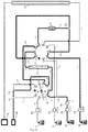
- FIG. 1 is a structural schematic diagram of a liquid chromatography in embodiment 1;
- FIG. 2 is a working state diagram of the liquid chromatography in embodiment 1;
- FIG. 3 is a working state diagram of the liquid chromatography in embodiment 1,
- FIG. 4 is a working state diagram of the liquid chromatography in embodiment 1;
- FIG. 5 is a working state diagram of the liquid chromatography in embodiment 1;
- FIG. 6 is a working state diagram of the liquid chromatography in embodiment 1;
- FIG. 7 is a working state diagram of the liquid chromatography in embodiment 1;
- FIG. 8 is a structural schematic diagram of a liquid chromatography in embodiment 2.
- FIG. 9 is a working state diagram of the liquid chromatography in embodiment 2.
- FIG. 10 is a working state diagram of the liquid chromatography in embodiment 2.
- FIG. 11 is a working state diagram of the liquid chromatography in embodiment 2.
- FIG. 12 is a working state diagram of the liquid chromatography in embodiment 2.
- FIG. 13 is a structural schematic diagram of a liquid chromatography in embodiment 3.
- FIG. 14 is a working state diagram of the liquid chromatography in embodiment 3.
- FIG. 15 is a working state diagram of the liquid chromatography in embodiment 3.
- FIG. 16 is a structural schematic diagram of a liquid chromatography in embodiment 4.
- FIG. 17 is a working state diagram of the liquid chromatography in embodiment 4.
- FIG. 18 is a working state diagram of the liquid chromatography in embodiment 4.
- FIG. 19 is a working state diagram of the liquid chromatography in embodiment 4.
- FIG. 20 is a working state diagram of the liquid chromatography in embodiment 4.
- FIG. 21 is a structural schematic diagram of a liquid chromatography in embodiment 5.
- FIG. 22 is a working state diagram of the liquid chromatography in embodiment 5.
- FIG. 23 is a working state diagram of the liquid chromatography in embodiment 5.
- S 1 represents a cleaning solution
- S 2 represents a second mobile phase
- S 3 represents a first mobile phase
- S 4 represents a modulation solution
- S 5 represents a sample injector
- P 1 represents a liquid conveying pump I
- P 2 represents a liquid conveying pump II
- P 3 represents a liquid conveying pump III
- P 4 represents a liquid conveying pump IV
- D represents a detector
- W represents a waste liquid flow outlet
- C 1 represents a first chromatographic column
- C 2 represents a middle chromatographic column
- C 3 represents a second chromatographic column
- V 1 represents a direction switch valve
- V 2 represents a multi-flow channel switch valve
- V 3 represents a rear switch valve note: V 1 -V 3 are all two-position switch valves)
- B 1 represents a cleaning solution storage ring
- B 2 represents a filter or protector
- T 1 represents a tee joint a
- T 2 represents a tee joint b
- T 3 represents
- L 3 represents a first flow channel
- L 21 represents a second flow channel
- L 22 represents an analysis flow channel
- L 14 represents a first waste liquid flow channel
- L 28 represents a second waste liquid flow channel
- L 31 represents a third waste liquid flow channel
- L 25 represents a cleaning flow channel
- L 13 represents a middle communication pipeline
- L 19 represents a connection pipeline
- L 17 represents a modulation flow channel I
- L 18 represents a modulation flow channel II
- L 14 ′ represents one segment of the first waste liquid flow channel L 14
- L 15 represents the other segment of the first waste liquid flow channel L 14
- L 3 ′ represents one segment of the first flow channel L 3
- L 7 represents the other segment of the first flow channel L 3
- L 8 represents a first pipeline which connects with the one end of the first chromatographic column
- L 9 represents a second pipeline which connects with the other end of the first chromatographic column
- L 12 represents a third pipeline which connects with the one end of the middle chromatographic column
- V 1 7 represents an interface a, 8 represents an interface b, 9 represents an interface c, 10 represents an interface d, 11 represents an interface e, 12 represents an interface f, 13 represents an interface g, 14 represents an interface h, 15 represents an interface i, and 16 represents an interface j;
- V 2 17 represents a port a, 18 represents a port b, 19 represents a port c, 20 represents a port d, 21 represents a port e, 22 represents a port f, 23 represents a port g, 24 represents a port h, 25 represents a port i and 26 represents a port j;
- V 5 1 represents an interface m, 2 represents an interface n, 3 represents an interface x, 4 represents an interface y, 5 represents an interface s and 6 represents an interface r;
- filled pot represent plugged states
- thick solid hues represent flow paths of the mobile phases.
- a liquid chromatography comprises:
- a first flow channel L 3 connected with a sample injector S 5 , which conveys a first mobile phase S 3 ;
- a second flow channel L 21 which conveys a second mobile phase S 2 ;
- a first chromatographic column C 1 which performs primary separation on a sample
- a middle chromatographic column C 2 which captures substances separated out by the first chromatographic column C 1 ;
- an analysis flow channel L 22 comprising a second chromatographic column C 3 and a detector D connected in sequence which further separate and detect the substances captured in the middle chromatographic column C 2 ;
- waste liquid flow channels L 28 , L 31 and L 14 which discharge waste liquid
- a cleaning flow channel L 25 which conveys a cleaning solution S 1 , a direction switch valve V 1 and a multi-flow channel switch valve V 2 ;
- the first chromatographic column C 1 is connected between the direction switch valve V 1 and the multi-flow channel switch valve V 2 ;
- a middle communication pipeline L 13 is arranged between the direction switch valve V 1 and the multi-flow channel switch valve V 2 which directly communicates the direction switch valve V 1 with the multi-flow channel switch valve V 2 ;
- the direction switch valve V 1 comprises an interface a 7 , an interface b 8 , an interface c 9 , an interface d 10 , an interface e 11 , an interface f 12 , an interface g 13 , an interface h 14 , an interface i 15 and an interface j 16 , a cleaning solution storage ring B 1 is connected between the interface e 11 and the interface j 16 , the interface a 7 is connected with the first flow channel L 3 , the interface b 8 is connected with first pipeline L 8 which connects with the one end of the first chromatographic column C 1 , the interface c 9 , the interface 112 and the interface h 14 are separately connected with the waste liquid flow channels, the interface d 10 is connected with the middle communication pipeline L 13 , the interface g 13 is in a plugged state, and the interface i 15 is connected with the cleaning flow channel L 25 .
- the multi-flow channel switch valve V 2 comprises a port a 17 , a port b 18 , a port c 19 , a port d 20 , a port e 21 , a port f 22 , a port g 23 , a port h 24 , a port i 25 and a port j 26 , the port c 19 and the port e 21 are in a plugged state, the port all is connected with the second pipeline L 9 which connects with the other end of the first chromatographic column C 1 , the port b 18 is connected with the port 122 through a connection pipeline L 19 , the port i 25 is connected with the third pipeline L 12 which connects with the one end of the middle chromatographic column C 2 , the fourth pipeline L 11 which connects with the other end of the middle chromatographic column C 2 is connected with the connection pipeline L 19 through a tee joint T 2 , the port g 23 is connected with the second flow channel L 21 , and the port h 24 is connected
- a separation function of the first chromatographic column as shown in FIG. 2 , a conveying pump III P 3 is started to convey the first mobile phase to the interface a 7 of the direction switch valve V 1 , a test sample is introduced by the sample injector S 5 , the interface a 7 and the interface b 8 of the direction switch valve V 1 are communicated, so that the first mobile phase flows across the first chromatographic column C 1 , the components in the test sample start to be separated under the separation mechanism of the first mobile phase and the first chromatographic column, then the first mobile phase containing the separated components flows to the port a 17 of the multi-flow channel switch valve V 2 , the port a 17 and the port j 26 of the multi-flow channel switch valve V 2 are communicated, so that the first mobile phase flows to the middle communication pipeline L 13 , then the interface d 10 of the direction switch valve V 1 is connected, and the interface d 10 and the interface c 9 are communicated, so that the first mobile phase flows to the first waste liquid flow channel L 14 to be discharged
- a capturing function of the middle chromatographic column as shown in FIG. 3 , the conveying pump III P 3 is stared to convey the first mobile phase to the interface a 7 of the direction switch valve V 1 , the interface a 7 and the interface b 8 of the direction switch valve V 1 are communicated, so that the first mobile phase flows across the first chromatographic column C 1 , the test sample is introduced through the sample injector S 5 , the components in the test sample start to be separated under the separation mechanism of the first mobile phase and the first chromatographic column, then the first mobile phase containing the separated components flows to the port a 17 of the multi-flow channel switch valve V 2 , the port a 17 and the port b 18 of the multi-flow channel switch valve V 2 are communicated, so that the first mobile phase flows across the middle chromatographic column C 2 , a target component contained in the first mobile phase is captured by the middle chromatographic column C 2 under the retention capacity of the middle chromatographic column C 2 and cannot be taken away by the first mobile phase, the first mobile phase flows
- a conveying pump II P 2 is started to convey the second mobile phase to the port g 23 of the multi-flow channel switch valve V 2 , the port g 23 and the port 122 are communicated, so that the second mobile phase flows across the middle chromatographic column C 2 , the above-mentioned target component is eluted by the second mobile phase and is contained in the second mobile phase to flow to the port i 25 , the port i 25 and the port h 24 are communicated, so that the second mobile phase flows across the analysis flow channel L 22 , finally the target component is further separated under the separation mechanism of the second mobile phase and the second chromatographic column C 3 , and the target component is detected by the detector D after flowing out from the second chromatographic column C 3 .
- a storage function of the cleaning solution as shown in FIG. 5 , a conveying pump I P 1 is started to convey the cleaning solution to a cleaning solution storage ring B 1 of the direction switch valve V 1 , then the cleaning solution is discharged from the second waste liquid flow channel L 28 , and thus the cleaning solution storage ring B 1 stores a part of the cleaning solution.
- the function can be executed within any rest time period without affecting the operation of the functions described in the above-mentioned regular functions, and requires no human intervention, and can be automatically accomplished.
- a cleaning function of the first chromatographic column as shown in FIG. 6 , the conveying pump 111 P 3 is stared to convey the first mobile phase to the interface a 7 of the direction switch valve V 1 , the interface a 7 and the interface j 16 are communicated, so that the first mobile phase pushes the cleaning solution in the cleaning solution storage ring B 1 to flow to the interface e 11 , the interface e 11 and the interface d 10 are communicated, the cleaning solution is conveyed to the port j 26 of the multi-flow channel switch valve V 2 by the middle communication pipeline L 13 , the port j 26 and the port all are communicated, so that the cleaning solution reversely flows into the first chromatographic column C 1 to clean the same and then flows into the interface b 8 of the direction switch valve V 1 , and the interface b 8 and the interface c 9 are communicated, so that the cleaning solution is discharged from the first waste liquid flow channel L 14 .
- This function and the separation function of the second chromatographic column can be executed at the same time and can
- a simultaneous cleaning function of the first chromatographic column and the middle chromatographic column as shown in FIG. 7 , a conveying pump P 3 is started to convey the first mobile phase to the interface a 7 of the direction switch valve V 1 , the interface a 7 and the interface j 16 are communicated, so that the first mobile phase pushes the cleaning solution in the cleaning solution storage ring B 1 to flow to the interface e 11 , the interface e 11 and the interface d 10 are communicated, the cleaning solution is conveyed to the port j 26 of the multi-flow channel switch valve V 2 by the middle communication pipeline L 13 , the port j 26 and the port i 25 are communicated, so that the cleaning solution flows into the middle chromatographic column C 2 to clean the same and then flows into the port b 18 of the multi-flow channel switch valve V 2 , the port b 18 and the port a 17 are communicated, so that the cleaning solution reversely flows into the first chromatographic column C 1 to clean the same and then flows into the interface b 8 of the direction switch
- a liquid chromatography on the basis of the liquid chromatography in embodiment 1, further comprises:
- modulation flow channel I L 17 which conveys modulation solution S 4 ;
- the modulation flow channel I L 17 is connected with the port e 21 of the multi-flow channel switch valve V 2 ;
- a modulation flow channel II L 18 wherein one end of the modulation flow channel II L 18 is connected with the port d 20 of the multi-flow channel switch valve V 2 , and the other end of the modulation flow channel II L 18 is connected with the first flow channel L 3 and is connected with the flow channel located behind the sample injector S 5 .
- a conveying pump IVP 4 is started to convey the modulation solution to the port e 21 of the multi-flow channel switch valve V 2 , the port e 21 and the port d 20 are communicated to convey the modulation solution to the modulation flow channel II L 18 , then the modulation solution is conveyed to the interface a 7 of the direction switch valve V 1 by the first flow channel L 13 , the interface a 7 and the interface b 8 of the direction switch valve V 1 are communicated, so that the modulation solution flows across the first chromatographic column C 1 , the impurities which is adaptive to the modulation solution and accumulated on the first chromatographic column C 1 can be cleaned because the modulation solution can be different from the first mobile phase, the cleaned modulation solution flows across the port a 17 of the multi-flow channel switch valve V 2 , the port a 17 and the port j 26 are communicated, so that the modulation solution flows to the middle communication pipeline L 13 , then the interface d 10 of the direction switch valve V 1 is communicate
- a conveying pump P 4 is started to convey the modulation solution to the port e 21 of the multi-flow channel switch valve V 2 , the port e 21 and the port f 22 are communicated to convey the modulation solution to the middle chromatographic column C 2 , the impurities which is adaptive to the modulation solution and accumulated on the middle chromatographic column C 2 can be cleaned because the modulation solution can be different from the first mobile phase, then the modulation solution flows to the port i 25 of the multi-flow channel switch valve V 2 , the port i 25 and the port j 26 are communicated, so that the modulation solution enters the interface d 10 of the direction switch valve V 1 through the middle communication pipeline L 13 , and the interface d 10 and the interface c 9 are communicated, so that the modulation solution flows to the first waste liquid flow channel L 14 to be discharged.
- the conveying pump III P 3 is stared to convey the first mobile phase to the interface a 7 of the direction switch valve V 1 , meanwhile the conveying pump P 4 is started to convey the modulation solution to the port e 21 of the multi-flow channel switch valve V 2 , the port e 21 and the port d 20 are communicated to convey the modulation solution to the modulation flow channel II L 18 , the first mobile phase and the modulation solution are mixed on the first flow channel L 3 , the modulation solution can be an acidic or alkaline solvent or a solvent containing special elution capacity, therefore the pH, the solvent proportion and the elution strength of the modulated first mobile phase are changed, the modulated mixed solution is conveyed to the interface a 7 of the direction switch valve V 1 , the interface a 7 and the interface b 8 are communicated, so that the above-mentioned mixed solution flows across the first chromatographic column C 1 , accordingly, the impurities which is adaptive to the mixed solution and accumulated on the
- the conveying pump III P 3 is stared to convey the first mobile phase to the interface a 7 of the direction switch valve V 1 , the interface a 7 and the interface b 8 of the direction switch valve V 1 are communicated, so that the first mobile phase flows across the first chromatographic column C 1 and then flows to the port a 17 of the multi-flow channel switch valve V 2 , and the port a 17 and the port b 18 are communicated, and the first mobile phase flows to the tee joint T 2 downstream; meanwhile, the conveying pump IVP 4 is started to convey the modulation solution to the port e 21 of the multi-flow channel switch valve V 2 , when the interface a 7 and the interface b 8 of the direction switch valve V 1 are connected, the port e 21 and the port 122 will be communicated, therefore the first mobile phase and the modulation solution are mixed on the tee joint T 2 to form a mixed solution, accordingly the pH, the solvent proportion and the elution strength of the modulated first mobile phase are changed
- a liquid chromatography on the basis of the liquid chromatography in embodiment 2, further comprises a rear switch valve V 5 , the rear switch valve V 5 is provided with an interface m 1 , an interface n 2 , an interface x 3 , an interface y 4 , an interface s 5 and interface r 6 ; a filter or a protector B 2 is connected between the interface n 2 and the interface s 5 ; interface y 4 is connected with one segment of the first waste liquid flow channel L 14 , and the interface x 3 is connected with the other segment of the first waste liquid flow channel L 14 ; and the interface m 1 is connected with one segment of the first flow channel L 3 , and the interface r 6 is connected with the other segment of the first flow channel L 3 .
- the conveying pump III P 3 is started to convey the first mobile phase to the interface m 1 of the rear switch valve V 5 , the test sample enters the first flow channel L 3 through the sample injector S 5 , the interface m 1 and the interface n 2 are communicated, so that the first mobile phase containing the test sample firstly flows across the filter or the protector B 2 , therefore the insoluble impurities contained in the test sample or the first mobile phase are intercepted by the filter or the protector B 2 and cannot enter the downstream pipelines, the interface s 5 and the interface r 6 are communicated, so that the filtered first mobile phase and the test sample are conveyed to the interface a 7 of the direction switch valve V 1 , the interface a 7 and the interface b 8 of the direction switch valve V 1 are communicated, so that the first mobile phase flows across the first chromatographic column C 1 and then flows to the port a 17 of the multi-flow channel switch valve V 2 , and the port a 17 and the port j 26 are communicated,
- the communication direction of the rear switch valve V 5 can be changed, the interface m 1 and the interface r 6 are communicated, the interface y 4 and the interface s 5 are communicated, and the interface m 2 and the interface x 3 are communicated, such that the filter or the protector is converted to the rear of the flow direction of the first chromatographic column by the rear switch valve, moreover, the flow direction of the solution in the filter or the protector is reverse to the direction in FIG. 14 , accordingly the impurities intercepted on the filter or the protector can be directly discharged to the waste liquid end, thus realizing function of cleaning the impurities brought in the test sample or the first mobile phase online, which is specifically as follows:
- the first mobile phase is conveyed to the interface m 1 of the rear switch valve V 5 , the interface m 1 and the interface r 6 are communicated, so that the first mobile phase is conveyed to the interface a 7 of the direction switch valve V 1 , the interface a 7 and the interface b 8 of the direction switch valve V 1 are communicated, so that the first mobile phase flows across the first chromatographic column C 1 and then flows to the port a 17 of the multi-flow channel switch valve V 2 , and the port a 17 and the port j 26 are communicated, so that the first mobile phase flows to the middle communication pipeline L 13 , then the interface d 10 of the direction switch valve V 1 is communicated, and the interface d 10 and the interface c 9 are communicated, so that the first mobile phase flows to one segment L 14 ′ of the first waste liquid flow channel, and the interface v 4 and the interface s 5 of the rear switch valve V 5 are connected, so that the first mobile phase reversely flows across the filter or the protector B 2 to clean the insoluble im
- a liquid chromatography comprises:
- a first flow channel L 3 connected with a sample injector S 5 , which conveys a first mobile phase S 3 ;
- a second flow channel L 21 which conveys a second mobile phase S 2 ;
- a first pipeline L 8 and a second pipeline L 9 which respectively connect with one end and the other end of a first chromatographic column C 1 ; the first chromatographic column C 1 , which performs primary separation on a sample;
- a third pipeline L 12 and a fourth pipeline L 11 which respectively connect with one end and the other end of a middle chromatographic column C 2 ; the middle chromatographic column C 2 , which captures substances separated out by the first chromatographic column C 1 ;
- an analysis flow channel L 22 comprising a second chromatographic column C 3 and a detector D connected in sequence which further separate and detect the substances captured in the middle chromatographic column C 2 ;
- the liquid chromatography further comprises a multi-flow channel switch valve V 2 provided with a plurality of ports, a connection pipeline L 19 is connected between any two ports of the multi-flow channel switch valve V 2 , and the third pipeline L 12 and the fourth pipeline L 11 which respectively connect with one end and the other end of the middle chromatographic column C 2 are arranged between the connection pipeline L 19 and another one of the rest ports;
- the first flow channel L 3 communicates with the first pipeline L 8 and the second pipeline L 9 which respectively connect with one end and the other end of the first chromatographic column C 1 and is connected with one of the ports of the multi-flow channel switch valve V 2 ;
- the second flow channel L 21 , the analysis flow channel L 22 and the fourth waste liquid flow channel L 32 are separately connected with any one of the rest ports of the multi-flow channel switch valve V 2 ;
- the liquid chromatography further comprises a modulation flow channel L 17 which conveys modulation solution S 4 ;
- the modulation flow channel I L 17 is connected with any one of the rest ports of the multi-flow channel switch valve V 2 ;
- the liquid chromatography further comprises a modulation flow channel II L 18 , wherein one end of the modulation flow channel II L 18 is connected with any one of the rest ports of the multi-flow channel switch valve V 2 , and the other end of the modulation flow channel II L 18 is connected with the first flow channel L 3 and is connected with the flow channel located behind the sample injector S 5 , or the other end of the modulation flow channel II L 18 is connected with the first pipeline L 8 which connects with the one end of the first chromatographic column C 1 .
- a preferred connection mode is as follows:
- the multi-flow channel switch valve comprises a port a 17 , a port b 18 , a port c 19 , a port d 20 , a port e 21 , a port f 22 , a port g 23 , a port h 24 , a port i 25 and a port j 26
- the port c 19 is in a plugged state
- the port a 17 is connected with the second pipeline L 9 which connects with the other end of the first chromatographic column C 1
- the port b 18 is connected with the port f 22 through the connection pipeline L 19
- the port i 25 is connected with the third pipeline L 12 which connects with the one end of the middle chromatographic column C 2
- the fourth pipeline L 11 which connects with the other end of the middle chromatographic column C 2 is connected with the connection pipeline L 19 through a tee joint bT 2
- the port g 23 is connected with the second flow channel L 21
- the port h 24 is connected with the analysis flow
- the conveying pump III P 3 is started, so that the first mobile phase flows across the first chromatographic column C 1 , the test sample is introduced by the sample injector S 5 , the components in the test sample start to be separated under the separation mechanism of the first mobile phase and the first chromatographic column, then the first mobile phase containing the separated components flows to the port a 17 of the multi-flow channel switch valve V 2 , the port a 17 and the port b 26 of the multi-flow channel switch valve V 2 are communicated, so that the first mobile phase flows to the fourth waste liquid flow channel L 32 to be discharged.
- the conveying pump III P 3 is stared, so that the first mobile phase flows across the first chromatographic column C 1 , the test sample is introduced by the sample injector S 5 , the components in the test sample start to be separated under the separation mechanism of the first mobile phase and the first chromatographic column, then the first mobile phase containing the separated components flows to the port all of the multi-flow channel switch valve V 2 , the port a 17 and the port b 18 of the multi-flow channel switch valve V 2 are communicated, so that the first mobile phase flows across the middle chromatographic column C 2 , the target component contained in the first mobile phase is captured by the middle chromatographic column C 2 and cannot be taken away by the first mobile phase, the first mobile phase flows to the port i 25 , and the port i 25 and the port j 26 are communicated, so that the first mobile phase flows to the fourth waste liquid flow channel L 32 to be discharged.
- the separation function of the second chromatographic column the conveying pump II P 2 is started to convey the second mobile phase to the port g 23 of the multi-flow channel switch valve V 2 , the port g 23 and the port f 22 are communicated, so that the second mobile phase flows across the middle chromatographic column C 2 , the above-mentioned target component is eluted by the second mobile phase and is contained in the second mobile phase to flow to the port i 25 , the port i 25 and the port h 24 are communicated, so that the second mobile phase flows across the analysis flow channel L 22 , finally the target component is further separated under the separation mechanism of the second mobile phase and the second chromatographic column C 3 , and the target component is detected by the detector D after flowing out from the second chromatographic column C 3 .
- the conveying pump IVP 4 is started to convey the modulation solution to the port e 21 of the multi-flow channel switch valve V 2 , the port e 21 and the port d 20 are communicated to convey the modulation solution to the modulation flow channel II L 18 , the modulation solution flows across the first chromatographic column C 1 , the impurities which is adaptive to the modulation solution and accumulated on the first chromatographic column C 1 can be cleaned because the modulation solution can be different from the first mobile phase, then the cleaned modulation solution flows across the port a 17 of the multi-flow channel switch valve V 2 , and the port a 17 and the port j 26 are communicated, so that the modulation solution flows to the fourth waste liquid flow channel L 32 to be discharged.
- the conveying pump P 4 is started to convey the modulation solution to the port e 21 of the multi-flow channel switch valve V 2 , the port e 21 and the port f 22 are communicated to convey the modulation solution to the middle chromatographic column C 2 , the impurities which is adaptive to the modulation solution and accumulated on the middle chromatographic column C 2 can be cleaned because the modulation solution can be different from the first mobile phase, then the modulation solution flows to the port i 25 of the multi-flow channel switch valve V 2 , and the port i 25 and the port j 26 are communicated, so that the modulation solution flows to the fourth waste liquid flow channel L 32 to be discharged.
- the conveying pump III P 3 is started, meanwhile the conveying pump P 4 is started to convey the modulation solution to the port e 21 of the multi-flow channel switch valve V 2 , the port e 21 and the port d 20 are communicated to convey the modulation solution to the modulation flow channel II L 18 , the first mobile phase and the modulation solution are mixed on the first flow channel L 3 , the modulation solution can be an acidic or alkaline solvent or a solvent containing special elution capacity, therefore the pH, the solvent proportion and the elution strength of the modulated first mobile phase are changed, the modulated mixed solution flows across the first chromatographic column C 1 , accordingly, the impurities which is adaptive to the mixed solution and accumulated on the first chromatographic column C 1 are cleaned, then the mixed solution flows across the port a 17 of the multi-flow channel switch valve V 2 , and the port a 17 and the port j 26 are communicated, so that the mixed solution flows to the fourth waste liquid flow channel L 32 to be
- the conveying pump III P 3 is stared, so that the first mobile phase flows across the first chromatographic column C 1 and then flows to the port a 17 of the multi-flow channel switch valve V 2 , and the port all and the port h 18 are communicated, so that the first mobile phase flows to the tee joint T 2 downstream; meanwhile, the conveying pump IVP 4 is started to convey the modulation solution to the port e 21 of the multi-flow channel switch valve V 2 , the port e 21 and the port f 22 are communicated, therefore the first mobile phase and the modulation solution are mixed on the tee joint T 2 to form a mixed solution, accordingly, the pH, the solvent proportion and the elution strength of the modulated first mobile phase are changed, the first mobile phase entering the middle chromatographic column is modulated, the above-mentioned mixed solution flows across the middle chromatographic column C 2 , and thus the impurities which is adaptive to the mixed solution and accumulated on the middle chromatographic column C 2 are cleaned
- a liquid chromatography comprises:
- a first flow channel L 3 connected with a sample injector S 5 , which conveys a first mobile phase S 3 ;
- a second flow channel L 21 which conveys a second mobile phase S 2 ;
- an analysis flow channel L 22 which separates and detects captured substances
- a first pipeline L 8 and a second pipeline L 9 which respectively connect with one end and the other end of a first chromatographic column C 1 ;
- a third L 12 and a fourth pipeline L 11 which connect with one end and the other end of a middle chromatographic column C 2 ;
- the liquid chromatography further comprises a rear switch valve V 5 and a multi-flow channel switch valve V 2 , and a communication pipeline L 34 which communicates the rear switch valve V 5 with the multi-flow channel switch valve V 2 ;
- the rear switch valve V 5 is provided with a plurality of interfaces, and any two adjacent interfaces of the rear switch valve V 5 are communicated with the first flow channel L 3 and the first pipeline L 8 , the first pipeline L 8 is connected with the one end of the first chromatographic column C 1 ; any other two adjacent interfaces of the rest interfaces are communicated with the fifth waste liquid flow channel L 33 and one end of the communication pipeline L 34 ; a filter or a protector B 2 is connected between any other two rest interfaces of the rear switch valve V 5 ; and
- the multi-flow channel switch valve V 2 is provided with a plurality of ports, a connection pipeline L 19 is connected between any two ports of the multi-flow channel switch valve V 2 , and the third pipeline L 12 and the fourth pipeline L 11 which respectively connect with one end and the other end of the middle chromatographic column C 2 are arranged between the connection pipeline L 19 and another one of the rest ports; the second flow channel L 21 , the analysis flow channel L 22 , the other end of the communication pipeline L 34 and the second pipeline L 9 are separately connected with any one of the rest ports of the multi-flow channel switch valve V 2 , the second pipeline L 9 is connected with the other end of the first chromatographic column C 1 .
- a preferred connection mode is as follows:
- the rear switch valve V 5 is provided with an interface m 1 , an interface n 2 , an interface x 3 , an interface y 4 , an interface s 5 and an interface r 6 ;
- the filter or the protector B 2 is connected between the interface n 2 and the interface s 5 ;
- the interface m 1 is connected with the first flow channel L 3
- the interface r 6 is connected with the first pipeline L 8 which connects with the one end of the first chromatographic column C 1
- the filter or the protector B 2 is connected between the interface n 2 and the interface s 5
- the interface x 3 is connected with the fifth waste liquid flow channel 133
- the interface y 4 is connected with one end of the communication pipeline L 34 .
- the multi-flow channel switch valve is provided with a port a 17 , a port b 18 , a port c 19 , a port d 20 , a port e 21 , a port f 22 , a port g 23 , a port h 24 , a port i 25 and a port j 26 , the port c 19 and the port e 21 are in a plugged state, the port a 17 is connected with the second pipeline L 9 which connects with the other end of the first chromatographic column C 1 , the port b 18 is connected with the port f 22 through the connection pipeline L 19 , the port i 25 is connected with the third pipeline L 12 which connects with the one end of the middle chromatographic column C 2 , the fourth pipeline L 11 which connects with the other end of the middle chromatographic column C 2 is connected with the connection pipeline L 19 through a tee joint bT 2 , the port g 23 is connected with the second flow channel L 21 , the port h
- the conveying pump III P 3 is started to convey the first mobile phase to the interface m 1 of the rear switch valve V 5 , the test sample is introduced into the first flow channel L 3 through the sample injector S 5 , the interface m 1 and the interface n 2 are communicated, so that the first mobile phase containing the test sample firstly flows across the filter or the protector 32 , therefore the insoluble impurities contained in the test sample or the first mobile phase are intercepted by the filter or the protector B 2 and cannot enter the downstream pipelines, the interface s 5 and the interface r 6 are communicated, so that the first mobile phase flows across the first chromatographic column C 1 and then flows to the port a 17 of the multi-flow channel switch valve V 2 , and the port a 17 and the port j 26 are communicated, so that the first mobile phase flows to the communication pipeline L 34 , and the interface y 4 and the interface x 3 of the rear switch valve V 5 are connected, so that the first mobile phase is discharged from the fifth waste liquid flow channel
- the communication direction of the rear switch valve V 5 can be changed, and the interface m 1 and the interface r 6 are communicated, the interface y 4 and the interface s 5 are communicated, and the interface m 2 and the interface x 3 are communicated, such that the filter or the protector is converted to the rear of the flow direction of the first chromatographic column by the rear switch valve, the flow direction of the solution in the filter or the protector is reverse to the direction in FIG. 22 , accordingly the impurities intercepted on the filter or the protector can be directly discharged to the waste liquid end, thus realizing function of cleaning the impurities brought in the test sample or the first mobile phase online, which is specifically as follows:
- the first mobile phase is conveyed to the interface m 1 of the rear switch valve V 5 , the interface m 1 and the interface r 6 are communicated, so that the first mobile phase flows across the first chromatographic column C 1 and then flows to the port a 17 of the multi-flow channel switch valve V 2 , and the port a 17 and the port j 26 are communicated, so that the first mobile phase flows to the communication pipeline L 34 , the interface v 4 and the interface s 5 of the rear switch valve V 5 are connected, so that the first mobile phase reversely flows across the filter or the protector B 2 to clean the insoluble impurities intercepted on the filter or the protector B 2 , then the first mobile phase flows to the waste liquid flow channel L 34 from the interface n 2 and the interface x 3 to be discharged, and thus the on-line cleaning function for the impurities is realized.
Landscapes
- Chemical & Material Sciences (AREA)
- Analytical Chemistry (AREA)
- Health & Medical Sciences (AREA)
- Life Sciences & Earth Sciences (AREA)
- General Physics & Mathematics (AREA)
- Physics & Mathematics (AREA)
- Biochemistry (AREA)
- General Health & Medical Sciences (AREA)
- Immunology (AREA)
- Pathology (AREA)
- Chemical Kinetics & Catalysis (AREA)
- Engineering & Computer Science (AREA)
- Biomedical Technology (AREA)
- Molecular Biology (AREA)
- Treatment Of Liquids With Adsorbents In General (AREA)
- Sampling And Sample Adjustment (AREA)
Abstract
Description
Claims (21)
Applications Claiming Priority (1)
| Application Number | Priority Date | Filing Date | Title |
|---|---|---|---|
| PCT/CN2014/092379 WO2016082154A1 (en) | 2014-11-27 | 2014-11-27 | Liquid phase chromatograph |
Publications (2)
| Publication Number | Publication Date |
|---|---|
| US20180128720A1 US20180128720A1 (en) | 2018-05-10 |
| US10859476B2 true US10859476B2 (en) | 2020-12-08 |
Family
ID=56073358
Family Applications (1)
| Application Number | Title | Priority Date | Filing Date |
|---|---|---|---|
| US15/531,706 Active 2035-11-28 US10859476B2 (en) | 2014-11-27 | 2014-11-27 | Liquid phase chromatograph |
Country Status (2)
| Country | Link |
|---|---|
| US (1) | US10859476B2 (en) |
| WO (1) | WO2016082154A1 (en) |
Families Citing this family (10)
| Publication number | Priority date | Publication date | Assignee | Title |
|---|---|---|---|---|
| EP3805246B1 (en) * | 2018-05-30 | 2025-02-19 | Hybio Pharmaceutical Co., Ltd. | Method for purifying long chain polypeptide ularitide |
| CN111257483B (en) * | 2018-11-30 | 2025-06-13 | 湖南德米特仪器有限公司 | A two-dimensional liquid chromatograph capable of reducing matrix effects of liquid chromatography-mass spectrometry |
| CN111289631A (en) * | 2018-12-07 | 2020-06-16 | 湖南德米特仪器有限公司 | Two-dimensional liquid chromatograph capable of directly analyzing biological liquid sample |
| CN110361556A (en) * | 2019-08-13 | 2019-10-22 | 深圳市康立生物医疗有限公司 | High speed electrolyte analyzer |
| CN110841369A (en) * | 2019-11-08 | 2020-02-28 | 南京中森生物科技有限公司 | High-temperature continuous acidification precipitation separation device and separation method for traditional Chinese medicine extracting solution |
| CN110988228B (en) * | 2019-11-25 | 2024-10-11 | 清华大学 | Automatic sampling and analysis device for multiple samples |
| CN113533541B (en) * | 2020-04-15 | 2022-07-08 | 中国科学院上海药物研究所 | A nanoliter liquid phase system with automatic cleaning function and control method |
| CN114354314B (en) * | 2021-12-31 | 2025-05-23 | 四川铸创安全科技有限公司 | Gas mixing and conveying device and sniffing system |
| CN115047113B (en) * | 2022-07-06 | 2023-08-15 | 南京品生医疗科技有限公司 | Liquid chromatograph |
| CN115031080A (en) * | 2022-07-19 | 2022-09-09 | 上海药明生基医药科技有限公司 | A column switching pipeline for AKTAReady chromatography system |
Citations (9)
| Publication number | Priority date | Publication date | Assignee | Title |
|---|---|---|---|---|
| US20040178133A1 (en) * | 2003-03-11 | 2004-09-16 | Kisaburo Deguchi | Separation analyzer |
| JP2011122822A (en) | 2009-12-08 | 2011-06-23 | Shimadzu Corp | Chromatograph mass analyzer |
| US20110303842A1 (en) | 2010-06-14 | 2011-12-15 | Shimadzu Corporation | Chromatograph Mass Spectrometer |
| US20130333452A1 (en) * | 2010-12-02 | 2013-12-19 | Hiroshi Suzuki | Liquid chromatograph, sample introduction device for liquid chromatograph, and method for cleaning sample introduction device for liquid chromatograph |
| US20140166542A1 (en) * | 2012-12-18 | 2014-06-19 | Exxonmobil Research And Engineering Company | Preparatory high performance liquid chromatographic (hplc) separation system and technique for quantitative fractionation of total vacuum resid |
| CN104330502A (en) | 2014-11-27 | 2015-02-04 | 王峰 | Liquid chromatograph |
| CN204203173U (en) | 2014-11-27 | 2015-03-11 | 王峰 | A kind of liquid chromatograph |
| CN204203174U (en) | 2014-11-27 | 2015-03-11 | 王峰 | A kind of liquid chromatograph |
| CN204203178U (en) | 2014-11-27 | 2015-03-11 | 王峰 | A kind of liquid chromatograph |
-
2014
- 2014-11-27 US US15/531,706 patent/US10859476B2/en active Active
- 2014-11-27 WO PCT/CN2014/092379 patent/WO2016082154A1/en not_active Ceased
Patent Citations (9)
| Publication number | Priority date | Publication date | Assignee | Title |
|---|---|---|---|---|
| US20040178133A1 (en) * | 2003-03-11 | 2004-09-16 | Kisaburo Deguchi | Separation analyzer |
| JP2011122822A (en) | 2009-12-08 | 2011-06-23 | Shimadzu Corp | Chromatograph mass analyzer |
| US20110303842A1 (en) | 2010-06-14 | 2011-12-15 | Shimadzu Corporation | Chromatograph Mass Spectrometer |
| US20130333452A1 (en) * | 2010-12-02 | 2013-12-19 | Hiroshi Suzuki | Liquid chromatograph, sample introduction device for liquid chromatograph, and method for cleaning sample introduction device for liquid chromatograph |
| US20140166542A1 (en) * | 2012-12-18 | 2014-06-19 | Exxonmobil Research And Engineering Company | Preparatory high performance liquid chromatographic (hplc) separation system and technique for quantitative fractionation of total vacuum resid |
| CN104330502A (en) | 2014-11-27 | 2015-02-04 | 王峰 | Liquid chromatograph |
| CN204203173U (en) | 2014-11-27 | 2015-03-11 | 王峰 | A kind of liquid chromatograph |
| CN204203174U (en) | 2014-11-27 | 2015-03-11 | 王峰 | A kind of liquid chromatograph |
| CN204203178U (en) | 2014-11-27 | 2015-03-11 | 王峰 | A kind of liquid chromatograph |
Non-Patent Citations (1)
| Title |
|---|
| International Search Report issued in International Application No. PCT/CN2014/092379 dated Sep. 2, 2015, 4 pages. |
Also Published As
| Publication number | Publication date |
|---|---|
| US20180128720A1 (en) | 2018-05-10 |
| WO2016082154A1 (en) | 2016-06-02 |
Similar Documents
| Publication | Publication Date | Title |
|---|---|---|
| US10859476B2 (en) | Liquid phase chromatograph | |
| CN102472731A (en) | A method in a chromatography system | |
| US20170010243A1 (en) | Multiple column chromatographic system and methods of use | |
| CN104330502B (en) | A kind of liquid chromatograph | |
| CN104297389A (en) | Chromatographic analysis system | |
| CN106290592B (en) | High performance liquid chromatography device and its working method | |
| US11821879B2 (en) | Autosampler for chromatograph | |
| JP2008209334A (en) | Liquid chromatography device | |
| CN104678014B (en) | A kind of Two-dimensional Liquid Chromatography | |
| CN110286174A (en) | A kind of online highly effective liquid phase chromatographic device of multidimensional | |
| CN104458978A (en) | Five-position eight-way valve and chromatogram system based on five-position eight-way valve | |
| JP6260719B2 (en) | Liquid chromatograph | |
| CN104678015A (en) | Liquid chromatograph | |
| CN104297391A (en) | Chromatographic analysis system | |
| WO2012095923A1 (en) | Analytical apparatus | |
| CN204203178U (en) | A kind of liquid chromatograph | |
| CN204203174U (en) | A kind of liquid chromatograph | |
| CN204203173U (en) | A kind of liquid chromatograph | |
| CN112433009A (en) | Chromatographic system for alternately and reversely cleaning chromatographic column by counting | |
| CN211263338U (en) | Two-dimensional liquid chromatograph capable of reducing matrix effect of LC-MS | |
| CN106546687A (en) | For the miniaturization device and its using method of GPC cleanup system system | |
| JP6639527B2 (en) | Two-dimensional liquid chromatography | |
| CN209416989U (en) | A kind of Two-dimensional Liquid Chromatography that can directly analyze biological fluid | |
| CN102243217B (en) | Backwashing flow path system of glycated hemoglobin analyzer | |
| CN121114285A (en) | Three-pump four-valve liquid chromatography system and analysis method |
Legal Events
| Date | Code | Title | Description |
|---|---|---|---|
| AS | Assignment |
Owner name: HUNAN DEMETER INSTRUMENTS CO., LTD., CHINA Free format text: ASSIGNMENT OF ASSIGNORS INTEREST;ASSIGNOR:WANG, FENG;REEL/FRAME:044014/0114 Effective date: 20170822 |
|
| STPP | Information on status: patent application and granting procedure in general |
Free format text: APPLICATION DISPATCHED FROM PREEXAM, NOT YET DOCKETED |
|
| STPP | Information on status: patent application and granting procedure in general |
Free format text: DOCKETED NEW CASE - READY FOR EXAMINATION |
|
| STPP | Information on status: patent application and granting procedure in general |
Free format text: NON FINAL ACTION MAILED |
|
| STPP | Information on status: patent application and granting procedure in general |
Free format text: RESPONSE TO NON-FINAL OFFICE ACTION ENTERED AND FORWARDED TO EXAMINER |
|
| STPP | Information on status: patent application and granting procedure in general |
Free format text: FINAL REJECTION MAILED |
|
| STPP | Information on status: patent application and granting procedure in general |
Free format text: DOCKETED NEW CASE - READY FOR EXAMINATION |
|
| STCF | Information on status: patent grant |
Free format text: PATENTED CASE |
|
| MAFP | Maintenance fee payment |
Free format text: PAYMENT OF MAINTENANCE FEE, 4TH YR, SMALL ENTITY (ORIGINAL EVENT CODE: M2551); ENTITY STATUS OF PATENT OWNER: SMALL ENTITY Year of fee payment: 4 |