US10859191B2 - Coupling arrangement for screw coupling - Google Patents
Coupling arrangement for screw coupling Download PDFInfo
- Publication number
- US10859191B2 US10859191B2 US15/383,763 US201615383763A US10859191B2 US 10859191 B2 US10859191 B2 US 10859191B2 US 201615383763 A US201615383763 A US 201615383763A US 10859191 B2 US10859191 B2 US 10859191B2
- Authority
- US
- United States
- Prior art keywords
- thread
- coupling arrangement
- connecting part
- clamping element
- accordance
- Prior art date
- Legal status (The legal status is an assumption and is not a legal conclusion. Google has not performed a legal analysis and makes no representation as to the accuracy of the status listed.)
- Active, expires
Links
Images


Classifications
-
- F—MECHANICAL ENGINEERING; LIGHTING; HEATING; WEAPONS; BLASTING
- F16—ENGINEERING ELEMENTS AND UNITS; GENERAL MEASURES FOR PRODUCING AND MAINTAINING EFFECTIVE FUNCTIONING OF MACHINES OR INSTALLATIONS; THERMAL INSULATION IN GENERAL
- F16L—PIPES; JOINTS OR FITTINGS FOR PIPES; SUPPORTS FOR PIPES, CABLES OR PROTECTIVE TUBING; MEANS FOR THERMAL INSULATION IN GENERAL
- F16L19/00—Joints in which sealing surfaces are pressed together by means of a member, e.g. a swivel nut, screwed on or into one of the joint parts
- F16L19/005—Joints in which sealing surfaces are pressed together by means of a member, e.g. a swivel nut, screwed on or into one of the joint parts comprising locking means for the threaded member
-
- F—MECHANICAL ENGINEERING; LIGHTING; HEATING; WEAPONS; BLASTING
- F16—ENGINEERING ELEMENTS AND UNITS; GENERAL MEASURES FOR PRODUCING AND MAINTAINING EFFECTIVE FUNCTIONING OF MACHINES OR INSTALLATIONS; THERMAL INSULATION IN GENERAL
- F16L—PIPES; JOINTS OR FITTINGS FOR PIPES; SUPPORTS FOR PIPES, CABLES OR PROTECTIVE TUBING; MEANS FOR THERMAL INSULATION IN GENERAL
- F16L19/00—Joints in which sealing surfaces are pressed together by means of a member, e.g. a swivel nut, screwed on or into one of the joint parts
- F16L19/02—Pipe ends provided with collars or flanges, integral with the pipe or not, pressed together by a screwed member
- F16L19/025—Pipe ends provided with collars or flanges, integral with the pipe or not, pressed together by a screwed member the pipe ends having integral collars or flanges
-
- B—PERFORMING OPERATIONS; TRANSPORTING
- B05—SPRAYING OR ATOMISING IN GENERAL; APPLYING FLUENT MATERIALS TO SURFACES, IN GENERAL
- B05B—SPRAYING APPARATUS; ATOMISING APPARATUS; NOZZLES
- B05B15/00—Details of spraying plant or spraying apparatus not otherwise provided for; Accessories
- B05B15/60—Arrangements for mounting, supporting or holding spraying apparatus
- B05B15/65—Mounting arrangements for fluid connection of the spraying apparatus or its outlets to flow conduits
-
- F—MECHANICAL ENGINEERING; LIGHTING; HEATING; WEAPONS; BLASTING
- F16—ENGINEERING ELEMENTS AND UNITS; GENERAL MEASURES FOR PRODUCING AND MAINTAINING EFFECTIVE FUNCTIONING OF MACHINES OR INSTALLATIONS; THERMAL INSULATION IN GENERAL
- F16L—PIPES; JOINTS OR FITTINGS FOR PIPES; SUPPORTS FOR PIPES, CABLES OR PROTECTIVE TUBING; MEANS FOR THERMAL INSULATION IN GENERAL
- F16L19/00—Joints in which sealing surfaces are pressed together by means of a member, e.g. a swivel nut, screwed on or into one of the joint parts
- F16L19/02—Pipe ends provided with collars or flanges, integral with the pipe or not, pressed together by a screwed member
- F16L19/0206—Pipe ends provided with collars or flanges, integral with the pipe or not, pressed together by a screwed member the collar not being integral with the pipe
Definitions
- the invention relates to a coupling arrangement for a screw coupling for liquid conduits of a high-pressure cleaning apparatus, wherein the coupling arrangement comprises a plug part capable of being pluggably connected to a complementarily configured plug part of a second coupling arrangement of the screw coupling for establishing a liquid-tight and releasable connection therewith with a sealing ring interposed therebetween, and wherein the coupling arrangement comprises a connecting part having a thread that is capable of being screwed together with a complementarily configured thread of the second coupling arrangement.
- Screw couplings are used in high-pressure cleaning apparatuses in order to enable liquid conduits to be connected together in a tight and releasable manner.
- a screw coupling it is for example possible for a high-pressure hose to be connected with the pressure outlet of a high-pressure cleaning appliance, and it is also possible for a releasable and liquid-tight connection to be produced between the pressure hose and a liquid discharge device which may, for example, be a spray gun.
- Such screw couplings also allow for a releasable and liquid-tight connection to be established between a spray gun and a spray lance and between a spray lance and a spray nozzle. The connections can be released again by the user as required.
- the screw couplings comprise a first coupling arrangement and a second coupling arrangement that can be screwed together.
- the first coupling arrangement comprises a first plug part that is capable of being pluggably connected to a second plug part of the second coupling arrangement complementary in configuration to the first plug part for establishing between them a liquid-tight and releasable connection with a sealing ring interposed therebetween.
- the first plug part may, for example, be configured in the form of a nipple and the second plug part may, for example, be configured in the form of a sleeve complementary in configuration to the nipple, wherein the nipple is capable of being inserted into the sleeve and is capable of being connected to the sleeve in a liquid-tight manner by use of a sealing ring.
- the sealing ring may be arranged in an outer annular groove of the nipple or in an inner annular groove of the sleeve.
- the first coupling arrangement and the second coupling arrangement comprise connecting parts which cooperate together and each of which comprises a thread so that the coupling arrangements can be screwed together.
- Coupling arrangements of the type mentioned at the outset are known for example from publication nos. DE 91 02 402 U1 and WO 96/08669 A1.
- the thread is arranged on a connecting part that is configured in the form of a union ring.
- the thread usually is of single-thread configuration and has a small lead angle, often amounting to approximately 2°.
- Such threads are self-locking and ensure that the first plug part cannot be inadvertently released from the second plug part even when the cleaning liquid pumped by the high-pressure cleaning apparatus is at high pressure.
- this object is accomplished in a coupling arrangement of the generic type by the thread being of a multiple-threaded configuration and by the connecting part comprising a clamping element aligned in an in-line relationship with the thread relative to the thread longitudinal axis, said clamping element being capable of being releasably clamped together with a complementarily configured clamping element of the second coupling arrangement by axially inserting one into the other.
- the coupling arrangement constructed in accordance with the invention uses a multiple, or multiple-start, thread, i.e. a thread in which multiple starting threads are wrapped helically around the thread longitudinal axis in parallel to each other.
- a multiple thread has the advantage that it allows the thread to have a large lead so that a large amount of axial movement can be achieved during one single revolution.
- a load imposed on the thread is simultaneously borne by multiple starting threads.
- the user need give the thread only one turn through a 360° revolution relative to the thread of the second coupling arrangement, this one single revolution being sufficient already for the plug part to be inserted into the complementarily configured plug part of the second coupling arrangement far enough for a liquid-tight connection between the plug parts to be reliably achieved.
- the coupling arrangement constructed in accordance with the invention uses in addition to the multiple thread a clamping element which is aligned in an in-line relationship relative to the thread longitudinal axis and can be clamped together with a complementarily configured clamping element of the second coupling arrangement by axially inserting the two clamping elements one into the other.
- the clamping elements can overlap in an axial direction, wherein the clamping elements are mutually clamped, thereby preventing inadvertent separation of the coupling arrangements.
- the multiple thread having a relatively large lead affords the user the possibility of making a liquid-tight connection in a very short time, wherein a large amount of axial movement is achieved in one single revolution of the thread, and the use of the clamping element enables an inadvertent release of the connection to be prevented despite the thread not necessarily being of self-locking configuration.
- the coupling arrangement is advantageous for the coupling arrangement to be capable of being connected to a complementarily configured coupling arrangement of the screw coupling without the use of tools.
- the user can thus establish and also release a liquid-tight connection between two liquid conduits of a high-pressure cleaning apparatus without the assistance of tools.
- the clamping element has an annular face oriented coaxially with the thread longitudinal axis, said annular face being capable of being clamped together with a complementarily configured annular face of the clamping element of the second coupling arrangement.
- the two annular faces can be inserted one into the other in an axial direction relative to the thread longitudinal axis so that one of the two annular faces surrounds the other annular face in a circumferential direction and the two annular faces are clamped together.
- annular face of the coupling arrangement constructed in accordance with the invention is of conical configuration.
- the annular face thus forms a frusto-conically shaped section of the connecting part that clampingly cooperates with a complementarily configured frusto-conically shaped section of the second coupling arrangement.
- the cone angle of the conical annular face is preferably approximately 2° to approximately 11°, in particular 5° to 6°.
- the term “cone angle” is used to denote the opening angle of the conical annular face, i.e. the opening angle of the frusto-conically shaped section of the connecting part. It has been shown that a relatively small cone angle facilitates the handling of the coupling arrangement in establishing a liquid-tight connection with a complementarily configured second coupling arrangement.
- cone angle of the conical annular face is particularly advantageous for the cone angle of the conical annular face to be 0.8 times to 1.2 times the lead angle of the thread.
- the lead angle of the thread is 5° to 6°.
- the number of starting threads of the multiple thread in the coupling arrangement constructed in accordance with the invention is preferably 2 to 6.
- a quadruple thread is particularly advantageous.
- the thread is advantageous for the thread to be configured in the form of a trapezoidal thread.
- a dirt-receiving space is arranged in an axial direction, between the thread and the clamping element.
- the dirt-receiving space is configured as an annular space that is oriented coaxially with the thread longitudinal axis.
- the annular space may be configured in the form of an annular groove integrally formed in the connecting part, in the area between the thread and the clamping element.
- the length of the dirt-receiving space in an axial direction is 0.7 times to 1.3 times the length of the thread.
- dirt-receiving space it is preferred for the dirt-receiving space to adjoin the thread directly in an axial direction.
- clamping element it is preferred for the clamping element to adjoin the dirt-receiving space directly in an axial direction.
- clamping element it is advantageous for the clamping element to extend in an axial direction over a length that is practically identical to the length of the multiple thread.
- the thread and the clamping element are connected together in one piece. They together thus form a one-piece component part of the coupling arrangement.
- the connecting part of the coupling arrangement is configured as a union ring that is supported on the plug part for free rotation and at most limited displacement in an axial direction, wherein the multiple thread is configured as an internal thread of the union ring and the clamping element is arranged on the inner side of the union ring.
- the plug part can be pluggably connected to a complementarily configured plug part of a second coupling arrangement with a sealing ring interposed therebetween, and a screw connection can be established between the coupling arrangement and the second coupling arrangement by way of the union ring.
- the union ring has an internal multiple thread and is supported on the plug part for free rotation and, preferably, practically no displacement in an axial direction.
- the internal thread is arranged between the point of support of the union ring and the free end face of the union ring, and the clamping element is positioned on the side of the internal thread facing away from the point of support of the union ring.
- the above-described dirt-receiving space is arranged between the internal thread and the clamping element.
- the clamping element is configured as an inner cone of the union ring whose internal diameter decreases with increasing distance from the free end face of the union ring.
- the inner cone extends to the free end face of the union ring.
- the inner cone thus adjoins the free end face of the union ring directly, and the multiple thread is positioned on the inner side of the union ring, at a location spaced from the free end face.
- the connecting part in the form of a union ring
- provision may be made, for example, for the connecting part to be connected to the plug part in a rigid manner and, in particular, in one piece.
- the plug part and the connecting part together can form a one-piece component part.
- the plug part may be configured in the form of a nipple-shaped or a sleeve-shaped extension which is adjoined in one piece by the connecting part in an axial direction.
- the thread is advantageous for the thread to be configured as an external thread and for the clamping element to be arranged on the outer side of the connecting part.
- the clamping element of the coupling arrangement is configured as an outer cone whose external diameter increases with increasing axial distance from the thread.
- the thread is configured as an internal thread and the clamping element is arranged on the inner side of the connecting part.
- the plug part may be configured in the form of a sleeve and the connecting part may be configured as a connecting ring arranged upstream of the sleeve, said connecting ring being oriented concentrically with the sleeve and carrying, on the inner side thereof, the internal thread and the clamping element.
- the clamping element is rigidly connected to the plug part and forms an inner cone whose internal diameter decreases with increasing distance from the free end face of the connecting part.
- the plug part prefferably carry the sealing ring and to have, in an axial direction, between the sealing ring and the thread, an annular groove in which an O-ring is arranged.
- O-ring By way of the O-ring, it is possible to prevent particulate debris from reaching the sealing ring when the plug part is plugged together with the complementarily configured plug part of the second coupling arrangement.
- the plug part of the coupling arrangement constructed in accordance with the invention may, for example, be configured as a nipple.
- a complementarily configured plug part of a second coupling arrangement may, for example, be configured as a sleeve into which the nipple is capable of being inserted with a sealing ring interposed between them.
- the sealing ring may be arranged in an annular groove that surrounds the nipple in a circumferential direction or in an annular groove incorporated in the wall of an internal bore of the sleeve.
- the nipple When the plug part is configured in the form of a nipple, it is advantageous for the nipple to comprise a first longitudinal section which has the sealing ring arranged therein and which extends from the free end face of the nipple to an enlargement of the nipple which is adjoined by a second longitudinal section of the nipple whose diameter is larger than the diameter of the first longitudinal section.
- the nipple is of stepped configuration, wherein the nipple is capable of having the first longitudinal section thereof come into sealing contact against a sealing face of a sleeve of the second coupling arrangement, with the sealing ring interposed therebetween.
- the second longitudinal section of the nipple can come into contact against a guide face of the sleeve located upstream of the sealing face in a direction of mating, said guide face facilitating insertion of the nipple into the sleeve.
- the plug part of the coupling arrangement constructed in accordance with the invention may, for example, also be configured in the form of a sleeve that has an internal bore.
- a complementarily configured plug part of a second coupling arrangement may, for example, be configured in the form of a nipple that is capable of being inserted into the internal bore of the sleeve.
- the sleeve may, on the inner side thereof, have an annular groove incorporated in the wall of the internal bore, said annular groove having the sealing ring positioned therein.
- provision may be made for the nipple that is capable of being inserted into the internal bore of the sleeve to carry on its outer side an annular groove in which the sealing ring is arranged.
- the connecting part of the coupling arrangement constructed in accordance with the invention may be configured as a union ring.
- the union ring can surround the sleeve in a circumferential direction and can be supported on the sleeve in rotationally fixed relation and for at most limited displacement in an axial direction.
- a retaining ring is used for supporting the union ring on the sleeve.
- the connecting part is connected to the sleeve in a rigid manner and, in particular, in one piece.
- the connecting part may surround the sleeve in a circumferential direction.
- the sleeve and the connecting part together may form a one-piece component part, wherein the sleeve forms the inner side of the component part and the connecting part forms the outer side of the component part.
- the component part On its outer side, the component part may comprise an external thread and a clamping element of preferably cone-shaped configuration.
- the component part On its inner side, the component part may form a sealing face against which a sealing ring is capable of being brought into sealing contact.
- connection part may be connected to the sleeve in a rigid manner and, in particular, in one piece and to be oriented coaxially with the sleeve.
- the connecting part may form a connecting ring having an internal thread into which a complementarily configured nipple having an external thread can be screwed.
- the connecting ring and the sleeve together may form a one-piece component part.
- the clamping element of preferably cone-shaped configuration may be arranged on the inner side of the connecting ring.
- the internal bore of the sleeve prefferably to form a sealing face against which a sealing ring is capable of being brought into sealing contact and which is adjoined in an axial direction by a guide face whose internal diameter is larger than the internal diameter of the sealing face.
- the guide face can extend to a free end face of the sleeve, advantageously wherein it widens continuously in an end region immediately adjacent to said end face. This facilitates insertion of a nipple into the sleeve.
- the invention further relates to a screw coupling for liquid conduits of a high-pressure cleaning apparatus, wherein by way of the screw coupling, a liquid-tight connection between two liquid conduits of the high-pressure cleaning apparatus is capable of being achieved in a short time, while ensuring that the connection is not inadvertently released.
- the screw coupling constructed in accordance with the invention comprises a first coupling arrangement of the kind constructed in accordance with the invention in which the plug part is configured in the form of a nipple and a second coupling arrangement of the kind constructed in accordance with the invention in which the plug part is configured as a sleeve, wherein the nipple of the first coupling arrangement is capable of being inserted into the sleeve of the second coupling arrangement with a sealing ring interposed therebetween, wherein the multiple thread of the second coupling arrangement is of complementary configuration to the multiple thread of the first coupling arrangement and the clamping element of the second coupling arrangement is complementary in configuration to the clamping element of the first coupling arrangement and wherein the two clamping elements are capable of being releasably clamped together by axially inserting one into the other.
- the two coupling arrangements are capable of being screwed together by way of the threads, wherein the threads have a complementary configuration relative to one another and are in each case of multiple-thread, preferably quadruple-thread, configuration. It is preferred for the nipple of the first coupling arrangement to be, during one single revolution of the two threads relative to each other, capable of being inserted into the complementarily configured sleeve of the second coupling arrangement in an axial direction sufficiently far for the nipple and the sleeve, together with the sealing ring arranged between the nipple and sleeve, to ensure a liquid-tight connection.
- the clamping elements of the two coupling arrangements When the two threads reach their final position, the clamping elements of the two coupling arrangements inserted one into the other in an axial direction clamp against each other.
- the clamping elements thus define the final position of the two threads when screwing the coupling arrangements together and ensure that the coupling arrangements cannot inadvertently be released from one another even when the cooperating threads are not self-locking.
- the two coupling arrangements comprise plug parts having a complementary configuration relative to each other, said plug parts being capable of being plugged one into the other with a sealing ring interposed therebetween, and the coupling arrangements additionally comprise connecting parts which each comprise a multiple thread and a clamping element.
- the clamping elements and the threads have a complementary configuration relative to each other.
- the sleeve prefferably to form on its inner side a sealing face against which a sealing ring held on the nipple of the first coupling arrangement is capable of being brought into sealing contact.
- clamping element of the second coupling arrangement prefferably configured as an annular face oriented coaxially with the thread longitudinal axis and, in particular, as a conical annular face.
- the annular face may form an outer cone that is arranged on the outer side of the sleeve.
- the second coupling arrangement whose plug part is configured as a sleeve to comprise a union ring that is supported on the sleeve for free rotation and at most limited displacement, preferably substantially no displacement, in an axial direction, wherein the thread of the second coupling arrangement is configured as an internal thread of the union ring and the clamping element of the second coupling arrangement is positioned on the inner side of the union ring.
- the clamping element may, for example, be configured in the form of an inner cone of the union ring.
- a dirt-receiving space is positioned between the multiple-start threads and the clamping elements of the coupling arrangements in each case, as has been discussed in detail hereinabove.
- the screw coupling constructed in accordance with the invention is preferably used for establishing a fluid-tight connection, capable of being released without tools, between the pressure outlet of a high-pressure cleaning apparatus and a pressure hose and/or between a pressure hose and a spray gun and/or between a spray gun and a spray lance and/or between a spray lance and a spray nozzle.
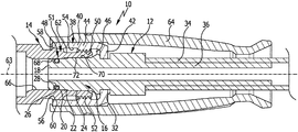
- FIG. 1 shows a schematic longitudinal sectional view of a first advantageous embodiment of a screw coupling having two coupling arrangements constructed in accordance with the invention
- FIG. 2 shows a schematic longitudinal sectional view of a second advantageous embodiment of a screw coupling having two coupling arrangements constructed in accordance with the invention.
- FIG. 3 shows a schematic longitudinal sectional view of a third advantageous embodiment of a screw coupling having two coupling arrangements constructed in accordance with the invention.
- FIG. 1 is a schematic representation of a first advantageous embodiment of a screw coupling, generally designated by the reference numeral 10 .
- the screw coupling 10 comprises a first coupling arrangement 12 and a second coupling arrangement 14 of complementary configuration, these being configured in accordance with the invention and easy to be screwed together in a liquid-tight manner without the use of tools and capable of being separated again from each other without tools as required.
- the first coupling arrangement 12 comprises a plug part in the form of a nipple 16 having a free end face 18 which is adjoined by a first longitudinal section 20 that transitions via an enlargement 22 into a second longitudinal section 24 .
- the diameter of the second longitudinal section 24 is larger than the diameter of the first longitudinal section 20 .
- the nipple 16 is formed with an annular groove 26 which has a sealing ring 28 arranged therein.
- the nipple 16 has a circumferential groove 32 .
- the nipple 16 is connected to a pressure hose 34 .
- the nipple 16 forms, in its end region facing away from the sealing ring 28 , a hollow connecting piece 36 onto which the pressure hose 34 is pressed.
- the connecting part 38 is configured as a union ring 40 which is supported in the circumferential groove 32 for free rotation and practically no displacement in an axial direction and which extends beyond the sealing ring 28 in an axial direction.
- the union ring 40 extends into the circumferential groove 32 by way of a rear wall 42 thereof.
- the rear wall 42 is connected in one piece to a circumferential wall 44 of the union ring 40 .
- the circumferential wall 44 and the nipple 16 define between them an annular intermediate space 46 into which the second coupling arrangement 14 extends by way of a plug part configured as a sleeve 48 .
- the union ring 40 has, on the inner side thereof, an internal multiple thread 50 that can be screwed onto an external multiple thread 52 of complementary configuration.
- the external thread 52 as well as an outer cone 60 that will be described in more detail below is formed by a connecting part 51 of the second coupling arrangement 14 which surrounds the sleeve in a circumferential direction and is connected to the sleeve 48 rigidly and in one piece.
- Adjoining the internal thread 50 in an axial direction is an annular dirt-receiving space 54 of the union ring 40 which is adjoined by an annular clamping element in the form of an inner cone 56 .
- the diameter of the inner cone 56 increases with increasing distance from the internal thread 50 .
- the inner cone extends to a free end face 58 of the union ring 40 facing away from the rear wall 42 .
- the connecting part 51 surrounding the sleeve 48 forms with the outer cone 60 that is arranged at a level of the inner cone 56 of the union ring 40 an annular clamping element of a configuration complementary to the inner cone 56 .
- the connecting part 51 has a dirt-receiving space 62 that is surrounded by the dirt-receiving space 54 of the union ring 40 .
- a longitudinal axis 63 of the screw coupling 10 forms a thread longitudinal axis of both the internal thread 50 and the external thread 52 .
- the inner cone 56 is aligned in an in-line relationship with the internal thread 50 relative to the thread longitudinal axis
- the outer cone 60 is aligned in an in-line relationship with the external thread 52 relative to the thread longitudinal axis.
- the sleeve 48 can be arranged for example at the pressure outlet of a high-pressure cleaning apparatus or also at the inlet or outlet of a spray gun or, for example, at the inlet of a spray nozzle by which a pressurized cleaning liquid can be directed onto an object to be cleaned.
- the nipple 16 can be arranged on a pressure hose 34 or also, for example, on a spray lance.
- the union ring 40 is surrounded by a grip sleeve 64 that is press-fit onto the union ring 40 and connected in rotationally fixed relationship therewith.
- the sleeve 48 comprises a cylindrical internal bore 66 having a sealing face 68 against which the sealing ring 28 is capable of being brought into sealing contact, and having a guide face 72 which adjoins the sealing face 68 in a direction towards the free end 70 of the sleeve 48 and whose internal diameter is larger than the internal diameter of the sealing face 68 .
- the nipple 16 can be inserted into the sleeve 48 , wherein first the first longitudinal section 20 of the nipple 16 enters the guide face 72 of the sleeve 48 and then the sleeve enters the annular intermediate space 46 between the circumferential wall 44 of the union ring 40 and the nipple 16 .
- the union ring 40 can be passed over the sleeve 48 in an axial direction sufficiently far for the external thread 52 of the sleeve 48 to come into engagement with the internal thread 50 of the union ring 40 .
- the smallest diameter of the inner cone 56 is selected to be larger than the external diameter of the external thread 52 so that the inner cone 56 can be pushed over the external thread 52 .
- the internal thread 50 can then be screwed together with the external thread 52 .
- the two threads each have a quadruple-thread configuration with a lead of 6 mm so that an axial travel of 6 mm can be realized in a single revolution.
- the inner cone 56 slides along the outer cone 60 and is, in a final position in which the internal thread 50 , after one revolution thereof, is fully screwed onto the external thread 52 and in which the sealing ring 28 is in liquid-tight contact against the sealing face 68 , clamped together with the outer cone 60 .
- the sealing ring 28 reaches the area of the guide face 72 before the internal thread 50 is fully separated from the external thread 52 . If the screw coupling 10 still has flow of pressurized liquid therethrough when the connection between the first coupling arrangement 12 and the second coupling arrangement 14 is being released, the connection will become leaky once the sealing ring 28 reaches the guide face 72 , and pressurized liquid can leak across the guide face 72 to the exterior without the screw connection being already fully disconnected.
- the emanating liquid can serve as a signal to indicate to the user that the screw coupling 10 still has flow of liquid therethrough. The user can then fully and promptly re-establish the screw connection by fully re-screwing the internal thread 50 onto the external thread 52 .
- the provision of the multi-start threads 50 and 52 makes it very easy for the user to establish and release the liquid-tight screw connection between the first coupling arrangement 12 and the second coupling arrangement 14 , and the provision of the inner and outer cones 56 , 60 which are capable of being axially inserted one into the other and clamped together can reliably counteract inadvertent release of the screw connection without the threads 50 and 52 having to be of a self-locking configuration.
- FIG. 2 is a schematic representation of a second advantageous embodiment of a screw coupling constructed in accordance with the invention, generally designed by the reference numeral 80 .
- the screw coupling 80 comprises a first coupling arrangement 82 and a second coupling arrangement 84 , these being configured in accordance with the invention and capable of being screwed together in a liquid-tight manner without the use of tools and of being separated again from each other without tools as required.
- the first coupling arrangement 82 comprises a plug part in the form of a nipple 86 having an annular groove 88 which has a sealing ring 90 arranged therein.
- the first coupling arrangement 82 comprises a connecting part 92 that is connected in one piece to the nipple 86 .
- the connecting part 92 is press-fit onto a jet tube 94 of a high-pressure cleaning apparatus.
- the connecting part 92 carries, on the outer side thereof, an external multiple thread 96 which is, in an axial direction and facing away from the nipple 86 , adjoined by a dirt-receiving space 98 which in turn is adjoined by a clamping element of the first coupling arrangement 82 in the form of an outer cone 100 .
- the first coupling arrangement 82 comprises a further annular groove 102 in which an O-ring 104 is arranged.
- the second coupling arrangement 84 comprises a plug part in the form of a sleeve 106 having a stepped internal bore 108 .
- the internal bore 108 comprises a cylindrical sealing face 110 which is adjoined by an outlet section 114 via a radially inwardly directed step 112 and which extends via a conical inlet section 116 to a free end 118 of the sleeve 106 .
- the sleeve 106 is connected in one piece with a housing 119 , only partially shown in the drawing, of a spray nozzle known per se and therefore not shown in the drawing in the interest of clarity.
- the sleeve 106 comprises, on the outer side thereof, an annular groove 120 in which a retaining ring 122 is held.
- the retaining ring 122 allows a connecting part 124 of the second coupling arrangement 84 to be supported on the sleeve 106 for free rotation and non-displacement in an axial direction.
- the connecting part 124 is configured in the form of a union ring 126 which surrounds the sleeve 106 in a circumferential direction and extends in an axial direction beyond the free end 118 of the sleeve 106 to the outer cone 100 of the first coupling arrangement 82 .
- the union ring 126 carries, on the inner side thereof, an inner cone 128 of complementary configuration to the outer cone 100 , said inner cone 128 being adjoined by a dirt-receiving space 130 of the union ring 126 .
- the dirt-receiving space 130 is adjoined by an internal multiple thread 132 of the union ring 126 having a configuration complementary to that of the external thread 96 of the first coupling arrangement 82 .
- a longitudinal axis 134 of the screw coupling 80 forms a thread longitudinal axis of both the external thread 96 and the internal thread 132 .
- the outer cone 100 is aligned in an in-line relation with the external thread 96 relative to the thread longitudinal axis
- the inner cone 128 is aligned in an in-line relationship with the internal thread 132 relative to the thread longitudinal axis.
- the nipple 86 can be inserted into the sleeve 106 before the external thread 96 comes into engagement with the internal thread 132 . Thereafter, the internal thread 132 can be screwed together with the external thread 96 , wherein an axial travel of approximately 6 mm is obtained in a single revolution, whereby the sealing ring 90 comes into sealing contact against the sealing face 110 and the inner cone 128 is clamped with the outer cone 110 .
- FIG. 3 is a schematic representation of a third advantageous embodiment of a screw coupling constructed in accordance with the invention, generally designed by the reference numeral 150 .
- the screw coupling 150 comprises a first coupling arrangement 152 comprising a plug part in the form of a nipple 154 and a second coupling arrangement 156 comprising a plug part in the form of a sleeve 158 .
- the first coupling arrangement 152 and the second coupling arrangement 156 are each configured in accordance with the invention and are capable of being screwed together in a liquid-tight manner without the use of tools and of being separated again from each other without tools as required.
- the nipple 154 has, on the outer side thereof, an annular groove 160 in which a sealing ring 162 is arranged, and, in accordance with the first coupling arrangement 82 described above with reference to FIG. 2 , the first coupling arrangement 152 likewise comprises a connecting part 164 that is connected with the nipple 154 in a rigid manner and, in the exemplary embodiment illustrated, in one piece, said connecting part 164 in the exemplary embodiment illustrated being press-fit onto a jet tube 166 .
- the connecting part 164 carries, on the outer side thereof, an external multiple thread 168 which is, in an axial direction and facing away from the nipple 154 , adjoined by a dirt-receiving space 170 which in turn is adjoined by a clamping element of the first coupling arrangement 152 in the form of an outer cone 172 .
- the first coupling arrangement 152 comprises a further annular groove 174 in which an O-ring 176 is arranged.
- the second coupling arrangement 156 comprises the above-mentioned sleeve 158 which in the exemplary embodiment illustrated is connected rigidly and in one piece to a housing 178 of a spray nozzle 180 . Via the spray nozzle 180 , cleaning liquid that has been pressurized by a high-pressure cleaning apparatus can be directed towards an object that is to be cleaned.
- the sleeve 158 comprises a stepped internal bore 182 comprising a cylindrical sealing face 184 which is, via a radially inwardly directed step 186 , adjoined by an outlet section 188 via which the pressurized cleaning liquid can be supplied to a conical nozzle orifice 190 .
- the sleeve 158 is adjoined, on the side thereof facing away from the nozzle housing 178 , by a connecting part 192 in the form of a connecting ring 194 configured coaxially with the sleeve 158 .
- the connecting ring 194 and the sleeve 158 are connected with each other rigidly and, in the exemplary embodiment illustrated, in one piece.
- the connecting ring 194 in combination with the sleeve 158 and the nozzle housing 178 forms a one-piece component part.
- the connecting ring 194 comprises an internal multiple thread 196 which is adjoined, on the side facing away from the sleeve 158 , by a dirt-receiving space 198 that surrounds the dirt-receiving space 170 of the first coupling arrangement 152 in a circumferential direction.
- Adjoining the dirt-receiving space 198 in an axial direction is a clamping element in the form of an inner cone 200 which is configured in a manner complementary to the outer cone 172 of the first coupling arrangement 152 .
- a longitudinal axis 202 of the screw coupling 150 forms a thread longitudinal axis of both the external thread 168 and the internal thread 196 .
- the outer cone 172 is aligned in an in-line relation with the external thread 168 relative to the thread longitudinal axis
- the inner cone 200 is aligned in an in-line relationship with the internal thread 196 relative to the thread longitudinal axis.
- the nipple 154 can be passed through the connecting ring 194 and inserted into the internal bore 182 of the sleeve 158 even before the external thread 168 comes into engagement with the internal thread 196 .
- the external thread 168 can then be screwed together with the internal thread 196 .
- the external thread 168 and the internal thread 196 are each formed with a multiple, preferably quadruple thread and preferably have a lead greater than 5 mm, in particular a lead of approximately 6 mm, so that an axial travel of approximately 6 mm is achieved for a single revolution of the internal thread 196 relative to the external thread 168 and the sealing ring 162 comes into sealing contact against the sealing face 184 and the inner cone 200 is clamped with the outer cone 172 .
- the lead angle of the internal and external threads 50 , 52 , 132 , 96 , 196 , 168 is 5° to 6°, preferably 5.2° to 5.8°, and the cone angle of the inner and outer cones 56 , 60 , 128 , 100 , 200 , 172 is 0.8 to 1.2 times the lead angle of the internal and external threads 50 , 52 , 132 , 96 , 196 , 168 .
- the internal and external threads 50 , 52 , 132 , 96 , 196 , 168 and the dirt-receiving spaces 54 , 62 , 98 , 130 , 170 , 198 are substantially the same length as the inner and outer cones 56 , 60 , 128 , 100 , 200 , 172 .
Abstract
Description
Claims (16)
Applications Claiming Priority (4)
| Application Number | Priority Date | Filing Date | Title |
|---|---|---|---|
| DE102014108699.6 | 2014-06-20 | ||
| DE102014108699 | 2014-06-20 | ||
| DE102014108699.6A DE102014108699A1 (en) | 2014-06-20 | 2014-06-20 | CLUTCH ASSEMBLY FOR SCREW COUPLING |
| PCT/EP2015/063034 WO2015193164A1 (en) | 2014-06-20 | 2015-06-11 | Coupling arrangement for screw coupling |
Related Parent Applications (1)
| Application Number | Title | Priority Date | Filing Date |
|---|---|---|---|
| PCT/EP2015/063034 Continuation WO2015193164A1 (en) | 2014-06-20 | 2015-06-11 | Coupling arrangement for screw coupling |
Publications (2)
| Publication Number | Publication Date |
|---|---|
| US20170097112A1 US20170097112A1 (en) | 2017-04-06 |
| US10859191B2 true US10859191B2 (en) | 2020-12-08 |
Family
ID=53442751
Family Applications (1)
| Application Number | Title | Priority Date | Filing Date |
|---|---|---|---|
| US15/383,763 Active 2036-10-14 US10859191B2 (en) | 2014-06-20 | 2016-12-19 | Coupling arrangement for screw coupling |
Country Status (9)
| Country | Link |
|---|---|
| US (1) | US10859191B2 (en) |
| EP (3) | EP3158249B1 (en) |
| JP (2) | JP6491680B2 (en) |
| CN (1) | CN106461129B (en) |
| AU (1) | AU2015276353B2 (en) |
| BR (1) | BR112016020452B1 (en) |
| DE (6) | DE102014108699A1 (en) |
| DK (3) | DK3158249T3 (en) |
| WO (1) | WO2015193164A1 (en) |
Families Citing this family (7)
| Publication number | Priority date | Publication date | Assignee | Title |
|---|---|---|---|---|
| DE102014108699A1 (en) | 2014-06-20 | 2015-12-24 | Alfred Kärcher Gmbh & Co. Kg | CLUTCH ASSEMBLY FOR SCREW COUPLING |
| DE102018101720A1 (en) * | 2018-01-25 | 2019-07-25 | Dt Swiss Ag | Hub especially for bicycles |
| US10933691B2 (en) * | 2017-07-26 | 2021-03-02 | Dt Swiss Inc. | Hub, in particular for bicycles |
| DE102017100357A1 (en) * | 2017-01-10 | 2018-07-12 | Alfred Kärcher Gmbh & Co. Kg | CLUTCH ASSEMBLY FOR SCREW COUPLING |
| CN107913868A (en) * | 2017-12-20 | 2018-04-17 | 常州格力博有限公司 | Jetting machine |
| DE102018101725A1 (en) * | 2018-01-25 | 2019-07-25 | Dt Swiss Ag | hub |
| CN109330249A (en) * | 2018-11-25 | 2019-02-15 | 倪旭涛 | Electronic self-locking seat riser |
Citations (33)
| Publication number | Priority date | Publication date | Assignee | Title |
|---|---|---|---|---|
| DE2650301A1 (en) | 1976-11-02 | 1978-05-03 | Hydrotechnik Gmbh | Hydraulic or pneumatic screw cap securing device - has link integral with mounting ring fitting by groove over flange |
| DE3018077A1 (en) | 1979-06-01 | 1980-12-18 | Pest Megyei Mueanyagipari | Quick-action pipe union - includes conical coupling member in socket with teeth pressed into inserted pipe |
| US4438884A (en) | 1981-11-02 | 1984-03-27 | Spraying Systems Company | Quick disconnect nozzle |
| EP0383029A2 (en) | 1989-01-17 | 1990-08-22 | Shop-Vac Corporation | Pressure washer with bypass |
| EP0444523A2 (en) | 1990-02-28 | 1991-09-04 | Suttner Gmbh & Co. Kg | Valve gun for a high-pressure cleaning device as well as a hose coupling, in particular for such a valve gun |
| FR2660983A1 (en) | 1990-04-12 | 1991-10-18 | Simmonds Sa | Leaktight connector which cannot be unscrewed |
| US5058930A (en) | 1990-03-09 | 1991-10-22 | Lourdes Industries | High pressure coupling with provision for preventing separation of parts and with anti-galling provision |
| DE9102402U1 (en) | 1991-02-28 | 1992-04-02 | Mosmatic Ag, Necker, Ch | |
| US5125694A (en) | 1990-04-13 | 1992-06-30 | Gianfranco Gobbi | Quick-connect and disconnect pipe-joint fitting |
| US5156421A (en) | 1990-02-05 | 1992-10-20 | Simmonds S.A. | Fluid-tight connectors for fluid-carrying pipe-lines |
| US5350200A (en) | 1994-01-10 | 1994-09-27 | General Electric Company | Tube coupling assembly |
| US5362110A (en) | 1991-02-25 | 1994-11-08 | Moeller Manufacturing Co., Inc. | Fluid coupling and fastener capture device |
| US5388866A (en) | 1990-03-09 | 1995-02-14 | Lourdes Industries | High pressure coupling with provision for preventing separation of parts and with anti-galling provision |
| US5649563A (en) | 1995-04-27 | 1997-07-22 | Surpass Industry Co., Ltd. | Fluid coupling |
| US5711822A (en) | 1994-11-30 | 1998-01-27 | Lucent Technologies Inc. | Method and apparatus for cleaning connectors |
| US5716078A (en) * | 1996-08-07 | 1998-02-10 | Powers; Ronald L. | Thermoplastic pipe joint |
| US5788292A (en) | 1994-09-12 | 1998-08-04 | Alfred Karcher Gmbh & Co. | Connector for the pipe coupling of a high-pressure cleaning apparatus |
| US6016975A (en) | 1997-07-31 | 2000-01-25 | Arrow Line S.R.L. | Axially-operated dual-action washing gun |
| EP1043080A1 (en) | 1999-03-29 | 2000-10-11 | Alto Danmark A/S | Ejection nozzle and handle assembly for a domestic high-pressure cleaner |
| WO2000077434A1 (en) | 1999-06-11 | 2000-12-21 | Airdrome Parts Co. | Self-locking coupling device |
| US6237968B1 (en) * | 1998-07-15 | 2001-05-29 | Walterscheid Rohrverbindungstechnik Gmbh | Pipe connector having a connecting portion formed onto one pipe end |
| WO2002089997A1 (en) | 2001-05-03 | 2002-11-14 | Nilfisk-Advance A/S | Quick-release coupling for the lance of a high-pressure cleaning device |
| CN1408058A (en) | 1999-12-15 | 2003-04-02 | 奥伊斯特泰克公司 | Hydraulic connectors |
| JP2003148661A (en) | 2001-11-08 | 2003-05-21 | Hard Lock Industry Co Ltd | Aseismatic pipe fitting |
| DE10217615A1 (en) | 2002-04-19 | 2003-11-06 | Bayerische Motoren Werke Ag | Coupling, esp. quick-fit coupling, for esp. fuel pipes in motor vehicles has two coupling elements with facing conical sealing surfaces to compress interior seal when connecting, to achieve zero emission |
| US20040061329A1 (en) | 2002-09-11 | 2004-04-01 | John Guest International Limited. | Tube couplings |
| EP1571385A2 (en) | 2004-03-05 | 2005-09-07 | Crane Co | Swivel pipe coupling with retention mechanism |
| US6991266B2 (en) * | 2001-04-20 | 2006-01-31 | Nippon Pillar Packing Co., Ltd. | Pipe joint made of resin |
| US7744018B2 (en) | 2006-05-30 | 2010-06-29 | Faip North America, Inc. | High pressure hydraulic system with hose fittings for diffusing pressure buildup upon uncoupling |
| US20100213705A1 (en) * | 2009-02-20 | 2010-08-26 | Swagelok Company | Conduit fitting with torque collar |
| US20130161941A1 (en) | 2011-12-26 | 2013-06-27 | The Gates Corporation | Hand tightened hydraulic fitting |
| WO2015193164A1 (en) | 2014-06-20 | 2015-12-23 | Alfred Kärcher Gmbh & Co. Kg | Coupling arrangement for screw coupling |
| EP3056782A1 (en) | 2015-02-16 | 2016-08-17 | Wirquin Plastiques | Connection member provided on a pipe, comprising a movable locking tip for coupling the pipe to a second pipe |
Family Cites Families (4)
| Publication number | Priority date | Publication date | Assignee | Title |
|---|---|---|---|---|
| JP2721402B2 (en) * | 1989-07-28 | 1998-03-04 | テイサン株式会社 | Pipe joint for low temperature liquefied gas |
| JP3821955B2 (en) * | 1997-01-30 | 2006-09-13 | 三菱伸銅株式会社 | Pipe connection structure, flexible pipe connection structure, and gas appliance |
| JP2003093692A (en) * | 2001-09-21 | 2003-04-02 | Heiwa Corp | Game machine frame and game machine |
| AU2002255291A1 (en) * | 2002-05-01 | 2003-11-17 | Fusao Yamada | Locking fastener |
-
2014
- 2014-06-20 DE DE102014108699.6A patent/DE102014108699A1/en active Pending
-
2015
- 2015-06-11 EP EP15730443.7A patent/EP3158249B1/en active Active
- 2015-06-11 DE DE202015009145.8U patent/DE202015009145U1/en active Active
- 2015-06-11 BR BR112016020452-2A patent/BR112016020452B1/en active IP Right Grant
- 2015-06-11 DE DE202015009176.8U patent/DE202015009176U1/en active Active
- 2015-06-11 CN CN201580020529.2A patent/CN106461129B/en active Active
- 2015-06-11 AU AU2015276353A patent/AU2015276353B2/en active Active
- 2015-06-11 JP JP2016573038A patent/JP6491680B2/en active Active
- 2015-06-11 WO PCT/EP2015/063034 patent/WO2015193164A1/en active Application Filing
- 2015-06-11 DK DK15730443.7T patent/DK3158249T3/en active
- 2015-06-11 DK DK18153669.9T patent/DK3339706T3/en active
- 2015-06-11 DE DE202015009177.6U patent/DE202015009177U1/en active Active
- 2015-06-11 EP EP17183454.2A patent/EP3263965B1/en active Active
- 2015-06-11 DE DE202015009179.2U patent/DE202015009179U1/en active Active
- 2015-06-11 DK DK17183454.2T patent/DK3263965T3/en active
- 2015-06-11 EP EP18153669.9A patent/EP3339706B1/en active Active
- 2015-06-11 DE DE202015009180.6U patent/DE202015009180U1/en active Active
-
2016
- 2016-12-19 US US15/383,763 patent/US10859191B2/en active Active
-
2018
- 2018-12-25 JP JP2018240587A patent/JP6653748B2/en active Active
Patent Citations (35)
| Publication number | Priority date | Publication date | Assignee | Title |
|---|---|---|---|---|
| DE2650301A1 (en) | 1976-11-02 | 1978-05-03 | Hydrotechnik Gmbh | Hydraulic or pneumatic screw cap securing device - has link integral with mounting ring fitting by groove over flange |
| DE3018077A1 (en) | 1979-06-01 | 1980-12-18 | Pest Megyei Mueanyagipari | Quick-action pipe union - includes conical coupling member in socket with teeth pressed into inserted pipe |
| US4438884A (en) | 1981-11-02 | 1984-03-27 | Spraying Systems Company | Quick disconnect nozzle |
| EP0383029A2 (en) | 1989-01-17 | 1990-08-22 | Shop-Vac Corporation | Pressure washer with bypass |
| US5156421A (en) | 1990-02-05 | 1992-10-20 | Simmonds S.A. | Fluid-tight connectors for fluid-carrying pipe-lines |
| EP0444523A2 (en) | 1990-02-28 | 1991-09-04 | Suttner Gmbh & Co. Kg | Valve gun for a high-pressure cleaning device as well as a hose coupling, in particular for such a valve gun |
| US5058930A (en) | 1990-03-09 | 1991-10-22 | Lourdes Industries | High pressure coupling with provision for preventing separation of parts and with anti-galling provision |
| US5388866A (en) | 1990-03-09 | 1995-02-14 | Lourdes Industries | High pressure coupling with provision for preventing separation of parts and with anti-galling provision |
| FR2660983A1 (en) | 1990-04-12 | 1991-10-18 | Simmonds Sa | Leaktight connector which cannot be unscrewed |
| US5125694A (en) | 1990-04-13 | 1992-06-30 | Gianfranco Gobbi | Quick-connect and disconnect pipe-joint fitting |
| US5362110A (en) | 1991-02-25 | 1994-11-08 | Moeller Manufacturing Co., Inc. | Fluid coupling and fastener capture device |
| DE9102402U1 (en) | 1991-02-28 | 1992-04-02 | Mosmatic Ag, Necker, Ch | |
| US5350200A (en) | 1994-01-10 | 1994-09-27 | General Electric Company | Tube coupling assembly |
| US5788292A (en) | 1994-09-12 | 1998-08-04 | Alfred Karcher Gmbh & Co. | Connector for the pipe coupling of a high-pressure cleaning apparatus |
| US5711822A (en) | 1994-11-30 | 1998-01-27 | Lucent Technologies Inc. | Method and apparatus for cleaning connectors |
| US5649563A (en) | 1995-04-27 | 1997-07-22 | Surpass Industry Co., Ltd. | Fluid coupling |
| US5716078A (en) * | 1996-08-07 | 1998-02-10 | Powers; Ronald L. | Thermoplastic pipe joint |
| US6016975A (en) | 1997-07-31 | 2000-01-25 | Arrow Line S.R.L. | Axially-operated dual-action washing gun |
| US6237968B1 (en) * | 1998-07-15 | 2001-05-29 | Walterscheid Rohrverbindungstechnik Gmbh | Pipe connector having a connecting portion formed onto one pipe end |
| EP1043080A1 (en) | 1999-03-29 | 2000-10-11 | Alto Danmark A/S | Ejection nozzle and handle assembly for a domestic high-pressure cleaner |
| WO2000077434A1 (en) | 1999-06-11 | 2000-12-21 | Airdrome Parts Co. | Self-locking coupling device |
| US20020008386A1 (en) | 1999-06-11 | 2002-01-24 | Airdrome Parts Co. | Self-locking coupling device |
| CN1408058A (en) | 1999-12-15 | 2003-04-02 | 奥伊斯特泰克公司 | Hydraulic connectors |
| US6991266B2 (en) * | 2001-04-20 | 2006-01-31 | Nippon Pillar Packing Co., Ltd. | Pipe joint made of resin |
| WO2002089997A1 (en) | 2001-05-03 | 2002-11-14 | Nilfisk-Advance A/S | Quick-release coupling for the lance of a high-pressure cleaning device |
| JP2003148661A (en) | 2001-11-08 | 2003-05-21 | Hard Lock Industry Co Ltd | Aseismatic pipe fitting |
| DE10217615A1 (en) | 2002-04-19 | 2003-11-06 | Bayerische Motoren Werke Ag | Coupling, esp. quick-fit coupling, for esp. fuel pipes in motor vehicles has two coupling elements with facing conical sealing surfaces to compress interior seal when connecting, to achieve zero emission |
| US20040061329A1 (en) | 2002-09-11 | 2004-04-01 | John Guest International Limited. | Tube couplings |
| EP1571385A2 (en) | 2004-03-05 | 2005-09-07 | Crane Co | Swivel pipe coupling with retention mechanism |
| US7744018B2 (en) | 2006-05-30 | 2010-06-29 | Faip North America, Inc. | High pressure hydraulic system with hose fittings for diffusing pressure buildup upon uncoupling |
| US20100213705A1 (en) * | 2009-02-20 | 2010-08-26 | Swagelok Company | Conduit fitting with torque collar |
| US20130161941A1 (en) | 2011-12-26 | 2013-06-27 | The Gates Corporation | Hand tightened hydraulic fitting |
| WO2013101534A1 (en) | 2011-12-26 | 2013-07-04 | The Gates Corporation | Hand tightened hydraulic fitting |
| WO2015193164A1 (en) | 2014-06-20 | 2015-12-23 | Alfred Kärcher Gmbh & Co. Kg | Coupling arrangement for screw coupling |
| EP3056782A1 (en) | 2015-02-16 | 2016-08-17 | Wirquin Plastiques | Connection member provided on a pipe, comprising a movable locking tip for coupling the pipe to a second pipe |
Also Published As
| Publication number | Publication date |
|---|---|
| WO2015193164A1 (en) | 2015-12-23 |
| DE102014108699A1 (en) | 2015-12-24 |
| CN106461129B (en) | 2019-11-19 |
| EP3263965A1 (en) | 2018-01-03 |
| EP3339706A1 (en) | 2018-06-27 |
| BR112016020452B1 (en) | 2021-02-23 |
| EP3158249A1 (en) | 2017-04-26 |
| DE202015009145U1 (en) | 2016-10-31 |
| DE202015009180U1 (en) | 2016-11-10 |
| EP3339706B1 (en) | 2021-08-04 |
| JP2017524878A (en) | 2017-08-31 |
| DE202015009177U1 (en) | 2016-11-08 |
| US20170097112A1 (en) | 2017-04-06 |
| EP3263965B1 (en) | 2020-04-22 |
| EP3158249B1 (en) | 2018-01-31 |
| DK3263965T3 (en) | 2020-07-20 |
| DK3339706T3 (en) | 2021-10-25 |
| DK3158249T3 (en) | 2018-04-30 |
| CN106461129A (en) | 2017-02-22 |
| AU2015276353A1 (en) | 2017-02-02 |
| DE202015009176U1 (en) | 2016-11-08 |
| DE202015009179U1 (en) | 2016-11-10 |
| JP2019113186A (en) | 2019-07-11 |
| JP6653748B2 (en) | 2020-02-26 |
| AU2015276353B2 (en) | 2018-09-13 |
| JP6491680B2 (en) | 2019-03-27 |
Similar Documents
| Publication | Publication Date | Title |
|---|---|---|
| US10859191B2 (en) | Coupling arrangement for screw coupling | |
| RU2739651C2 (en) | Hose and hose adapter | |
| TWI299925B (en) | ||
| US20190226615A1 (en) | Joint Assembly | |
| EP3002492A1 (en) | Inlet water pipe | |
| US20190331263A1 (en) | Coupling arrangement for screw coupling | |
| CA2835162C (en) | Hose connection arrangement | |
| WO2013142887A3 (en) | Plug part and socket part for detachably connecting a tube elbow of a gas-cooled welding torch to a hose packet, and connecting device with such a plug part and socket part | |
| JP7004386B2 (en) | Pipe fittings and fitting connecting devices | |
| EP0957305A2 (en) | A pneumatic connector | |
| JP2012511124A (en) | Conduit structure for hot water tap and the tap | |
| US10060561B2 (en) | Connecting system and method for connecting fluid-conducting components | |
| CN104930283B (en) | Screw connection for double-wall pipe | |
| JP6515822B2 (en) | Pipe fitting | |
| US8672365B2 (en) | Quick connect coupling having inverted guide and sealing zones | |
| EP2333167A1 (en) | Connector with integral sleeve portion and pipe with such a connector | |
| JP6516079B2 (en) | Pipe fitting | |
| KR101139766B1 (en) | Couple for hydraulic line | |
| JP2008019980A (en) | Hose connection pipe joint | |
| US1113770A (en) | Hose-coupling. | |
| US20150240973A1 (en) | Spigot couplings | |
| JP2019090540A (en) | Joint for piping | |
| JP5711433B1 (en) | Fixing structure of tube body in endoscope cleaning sheath, endoscope cleaning sheath applying this tube body fixing structure, and endoscope system including this endoscope cleaning sheath | |
| SE509268C2 (en) | Device for connecting pipes to a clamping ring connection | |
| JP6546740B2 (en) | Plug body |
Legal Events
| Date | Code | Title | Description |
|---|---|---|---|
| AS | Assignment |
Owner name: ALFRED KAERCHER GMBH & CO. KG, GERMANY Free format text: ASSIGNMENT OF ASSIGNORS INTEREST;ASSIGNORS:LANGER, CHRISTIAN;WEISS, BENJAMIN;SEITTER, RALPH;SIGNING DATES FROM 20170123 TO 20170214;REEL/FRAME:041386/0840 |
|
| AS | Assignment |
Owner name: ALFRED KAERCHER SE & CO. KG, GERMANY Free format text: CHANGE OF NAME;ASSIGNOR:ALFRED KAERCHER GMBH & CO. KG;REEL/FRAME:047181/0800 Effective date: 20180705 |
|
| STPP | Information on status: patent application and granting procedure in general |
Free format text: RESPONSE TO NON-FINAL OFFICE ACTION ENTERED AND FORWARDED TO EXAMINER |
|
| STPP | Information on status: patent application and granting procedure in general |
Free format text: NON FINAL ACTION MAILED |
|
| STPP | Information on status: patent application and granting procedure in general |
Free format text: RESPONSE TO NON-FINAL OFFICE ACTION ENTERED AND FORWARDED TO EXAMINER |
|
| STPP | Information on status: patent application and granting procedure in general |
Free format text: FINAL REJECTION MAILED |
|
| STPP | Information on status: patent application and granting procedure in general |
Free format text: DOCKETED NEW CASE - READY FOR EXAMINATION |
|
| STPP | Information on status: patent application and granting procedure in general |
Free format text: EX PARTE QUAYLE ACTION MAILED |
|
| STPP | Information on status: patent application and granting procedure in general |
Free format text: RESPONSE TO EX PARTE QUAYLE ACTION ENTERED AND FORWARDED TO EXAMINER |
|
| STCF | Information on status: patent grant |
Free format text: PATENTED CASE |