US10855488B2 - Scheduled automation associations for a lighting control system - Google Patents
Scheduled automation associations for a lighting control system Download PDFInfo
- Publication number
- US10855488B2 US10855488B2 US16/694,468 US201916694468A US10855488B2 US 10855488 B2 US10855488 B2 US 10855488B2 US 201916694468 A US201916694468 A US 201916694468A US 10855488 B2 US10855488 B2 US 10855488B2
- Authority
- US
- United States
- Prior art keywords
- devices
- user
- lighting
- lighting control
- user interface
- Prior art date
- Legal status (The legal status is an assumption and is not a legal conclusion. Google has not performed a legal analysis and makes no representation as to the accuracy of the status listed.)
- Active
Links
- 238000004891 communication Methods 0.000 claims abstract description 30
- 230000000694 effects Effects 0.000 claims abstract description 20
- 238000000034 method Methods 0.000 claims description 32
- 238000001514 detection method Methods 0.000 claims description 13
- 230000003993 interaction Effects 0.000 claims description 11
- 230000001934 delay Effects 0.000 claims description 2
- 230000007613 environmental effect Effects 0.000 claims 6
- 238000009434 installation Methods 0.000 abstract description 16
- 238000012544 monitoring process Methods 0.000 abstract description 12
- 230000001419 dependent effect Effects 0.000 abstract description 3
- 238000005286 illumination Methods 0.000 description 15
- 230000008520 organization Effects 0.000 description 14
- 230000008901 benefit Effects 0.000 description 13
- 230000008569 process Effects 0.000 description 13
- 230000001413 cellular effect Effects 0.000 description 12
- 230000006870 function Effects 0.000 description 11
- 230000009471 action Effects 0.000 description 6
- 230000033001 locomotion Effects 0.000 description 6
- 238000003825 pressing Methods 0.000 description 6
- 230000006399 behavior Effects 0.000 description 5
- 239000003990 capacitor Substances 0.000 description 5
- 230000008859 change Effects 0.000 description 5
- 230000004044 response Effects 0.000 description 5
- 230000000977 initiatory effect Effects 0.000 description 4
- 238000005259 measurement Methods 0.000 description 4
- 241001124569 Lycaenidae Species 0.000 description 3
- 230000005540 biological transmission Effects 0.000 description 3
- 239000000203 mixture Substances 0.000 description 3
- 238000003860 storage Methods 0.000 description 3
- 230000003213 activating effect Effects 0.000 description 2
- 230000010267 cellular communication Effects 0.000 description 2
- 238000012508 change request Methods 0.000 description 2
- 230000007423 decrease Effects 0.000 description 2
- 238000003306 harvesting Methods 0.000 description 2
- 238000013507 mapping Methods 0.000 description 2
- 238000012549 training Methods 0.000 description 2
- 230000000007 visual effect Effects 0.000 description 2
- 230000004075 alteration Effects 0.000 description 1
- 238000012790 confirmation Methods 0.000 description 1
- 230000000994 depressogenic effect Effects 0.000 description 1
- 238000013461 design Methods 0.000 description 1
- 238000010586 diagram Methods 0.000 description 1
- 238000007599 discharging Methods 0.000 description 1
- 230000001976 improved effect Effects 0.000 description 1
- 238000011900 installation process Methods 0.000 description 1
- 230000002452 interceptive effect Effects 0.000 description 1
- 239000000463 material Substances 0.000 description 1
- 230000000116 mitigating effect Effects 0.000 description 1
- 238000012986 modification Methods 0.000 description 1
- 230000004048 modification Effects 0.000 description 1
- 230000006855 networking Effects 0.000 description 1
- 230000003287 optical effect Effects 0.000 description 1
- 230000037361 pathway Effects 0.000 description 1
- 238000012545 processing Methods 0.000 description 1
- 230000001737 promoting effect Effects 0.000 description 1
- 238000001650 pulsed electrochemical detection Methods 0.000 description 1
- 230000000630 rising effect Effects 0.000 description 1
- 239000004065 semiconductor Substances 0.000 description 1
- 238000012546 transfer Methods 0.000 description 1
Images


Classifications
-
- H—ELECTRICITY
- H04—ELECTRIC COMMUNICATION TECHNIQUE
- H04L—TRANSMISSION OF DIGITAL INFORMATION, e.g. TELEGRAPHIC COMMUNICATION
- H04L12/00—Data switching networks
- H04L12/28—Data switching networks characterised by path configuration, e.g. LAN [Local Area Networks] or WAN [Wide Area Networks]
- H04L12/2803—Home automation networks
- H04L12/2823—Reporting information sensed by appliance or service execution status of appliance services in a home automation network
- H04L12/2827—Reporting to a device within the home network; wherein the reception of the information reported automatically triggers the execution of a home appliance functionality
- H04L12/2829—Reporting to a device within the home network; wherein the reception of the information reported automatically triggers the execution of a home appliance functionality involving user profiles according to which the execution of a home appliance functionality is automatically triggered
-
- H—ELECTRICITY
- H04—ELECTRIC COMMUNICATION TECHNIQUE
- H04L—TRANSMISSION OF DIGITAL INFORMATION, e.g. TELEGRAPHIC COMMUNICATION
- H04L12/00—Data switching networks
- H04L12/28—Data switching networks characterised by path configuration, e.g. LAN [Local Area Networks] or WAN [Wide Area Networks]
- H04L12/46—Interconnection of networks
- H04L12/4604—LAN interconnection over a backbone network, e.g. Internet, Frame Relay
- H04L12/462—LAN interconnection over a bridge based backbone
- H04L12/4625—Single bridge functionality, e.g. connection of two networks over a single bridge
-
- H—ELECTRICITY
- H04—ELECTRIC COMMUNICATION TECHNIQUE
- H04L—TRANSMISSION OF DIGITAL INFORMATION, e.g. TELEGRAPHIC COMMUNICATION
- H04L67/00—Network arrangements or protocols for supporting network services or applications
- H04L67/01—Protocols
- H04L67/12—Protocols specially adapted for proprietary or special-purpose networking environments, e.g. medical networks, sensor networks, networks in vehicles or remote metering networks
- H04L67/125—Protocols specially adapted for proprietary or special-purpose networking environments, e.g. medical networks, sensor networks, networks in vehicles or remote metering networks involving control of end-device applications over a network
-
- H04W12/0804—
-
- H—ELECTRICITY
- H04—ELECTRIC COMMUNICATION TECHNIQUE
- H04W—WIRELESS COMMUNICATION NETWORKS
- H04W12/00—Security arrangements; Authentication; Protecting privacy or anonymity
- H04W12/08—Access security
- H04W12/084—Access security using delegated authorisation, e.g. open authorisation [OAuth] protocol
-
- H—ELECTRICITY
- H04—ELECTRIC COMMUNICATION TECHNIQUE
- H04W—WIRELESS COMMUNICATION NETWORKS
- H04W24/00—Supervisory, monitoring or testing arrangements
- H04W24/08—Testing, supervising or monitoring using real traffic
-
- H—ELECTRICITY
- H05—ELECTRIC TECHNIQUES NOT OTHERWISE PROVIDED FOR
- H05B—ELECTRIC HEATING; ELECTRIC LIGHT SOURCES NOT OTHERWISE PROVIDED FOR; CIRCUIT ARRANGEMENTS FOR ELECTRIC LIGHT SOURCES, IN GENERAL
- H05B45/00—Circuit arrangements for operating light-emitting diodes [LED]
- H05B45/10—Controlling the intensity of the light
-
- H—ELECTRICITY
- H05—ELECTRIC TECHNIQUES NOT OTHERWISE PROVIDED FOR
- H05B—ELECTRIC HEATING; ELECTRIC LIGHT SOURCES NOT OTHERWISE PROVIDED FOR; CIRCUIT ARRANGEMENTS FOR ELECTRIC LIGHT SOURCES, IN GENERAL
- H05B47/00—Circuit arrangements for operating light sources in general, i.e. where the type of light source is not relevant
- H05B47/10—Controlling the light source
- H05B47/105—Controlling the light source in response to determined parameters
- H05B47/11—Controlling the light source in response to determined parameters by determining the brightness or colour temperature of ambient light
-
- H—ELECTRICITY
- H05—ELECTRIC TECHNIQUES NOT OTHERWISE PROVIDED FOR
- H05B—ELECTRIC HEATING; ELECTRIC LIGHT SOURCES NOT OTHERWISE PROVIDED FOR; CIRCUIT ARRANGEMENTS FOR ELECTRIC LIGHT SOURCES, IN GENERAL
- H05B47/00—Circuit arrangements for operating light sources in general, i.e. where the type of light source is not relevant
- H05B47/10—Controlling the light source
- H05B47/105—Controlling the light source in response to determined parameters
- H05B47/115—Controlling the light source in response to determined parameters by determining the presence or movement of objects or living beings
-
- H—ELECTRICITY
- H05—ELECTRIC TECHNIQUES NOT OTHERWISE PROVIDED FOR
- H05B—ELECTRIC HEATING; ELECTRIC LIGHT SOURCES NOT OTHERWISE PROVIDED FOR; CIRCUIT ARRANGEMENTS FOR ELECTRIC LIGHT SOURCES, IN GENERAL
- H05B47/00—Circuit arrangements for operating light sources in general, i.e. where the type of light source is not relevant
- H05B47/10—Controlling the light source
- H05B47/175—Controlling the light source by remote control
- H05B47/19—Controlling the light source by remote control via wireless transmission
-
- H05B47/199—
-
- H—ELECTRICITY
- H04—ELECTRIC COMMUNICATION TECHNIQUE
- H04L—TRANSMISSION OF DIGITAL INFORMATION, e.g. TELEGRAPHIC COMMUNICATION
- H04L63/00—Network architectures or network communication protocols for network security
- H04L63/02—Network architectures or network communication protocols for network security for separating internal from external traffic, e.g. firewalls
- H04L63/0227—Filtering policies
-
- H—ELECTRICITY
- H04—ELECTRIC COMMUNICATION TECHNIQUE
- H04W—WIRELESS COMMUNICATION NETWORKS
- H04W84/00—Network topologies
- H04W84/18—Self-organising networks, e.g. ad-hoc networks or sensor networks
-
- H—ELECTRICITY
- H04—ELECTRIC COMMUNICATION TECHNIQUE
- H04W—WIRELESS COMMUNICATION NETWORKS
- H04W88/00—Devices specially adapted for wireless communication networks, e.g. terminals, base stations or access point devices
- H04W88/16—Gateway arrangements
-
- Y—GENERAL TAGGING OF NEW TECHNOLOGICAL DEVELOPMENTS; GENERAL TAGGING OF CROSS-SECTIONAL TECHNOLOGIES SPANNING OVER SEVERAL SECTIONS OF THE IPC; TECHNICAL SUBJECTS COVERED BY FORMER USPC CROSS-REFERENCE ART COLLECTIONS [XRACs] AND DIGESTS
- Y02—TECHNOLOGIES OR APPLICATIONS FOR MITIGATION OR ADAPTATION AGAINST CLIMATE CHANGE
- Y02B—CLIMATE CHANGE MITIGATION TECHNOLOGIES RELATED TO BUILDINGS, e.g. HOUSING, HOUSE APPLIANCES OR RELATED END-USER APPLICATIONS
- Y02B20/00—Energy efficient lighting technologies, e.g. halogen lamps or gas discharge lamps
- Y02B20/40—Control techniques providing energy savings, e.g. smart controller or presence detection
-
- Y02B20/445—
-
- Y02B20/46—
Definitions
- the present disclosure relates generally to control devices, and more particularly to configurable associations for wireless lighting control systems.
- wireless lighting control systems facilitate control and automation of lighting fixtures. That is, various electrical devices may be configured to operate according to predetermined schedules or events, such as in response to time or other user selections and preferences. Remote monitoring or wireless control of certain electrical devices is also offered, including the monitoring or controlling of electrical devices over a network using a mobile device.
- automation and control, including wireless control, of electrical devices becomes more popular and as the desired control becomes more complex, there is a need for robust device control systems that are relatively straightforward to install, configure, and use. Although some relatively sophisticated systems are available, they typically require extensive wiring and other installation steps by technicians specially trained in such systems and are expensive and complex to install and maintain.
- One such device configuration is user control devices.
- wireless wall switches For example, wireless wall switches.
- One such prior art wireless wall switch requires the installer to physically access a pairing switch on each of a wireless wall switch and a wireless controller that switches/dims the light fixture to be associated with the wall switch. Such physical access is often not convenient or practical depending on the physical locations of the devices involved.
- the present disclosure is directed to one or more of the problems or issues set forth above.
- the present disclosure includes a wireless lighting control system.
- the wireless lighting control system includes a cloud-based or other remote server system connected to a wide area network and having control software for configuring, monitoring, and controlling lighting fixtures at an organization's installation site.
- the wireless lighting control system also includes a wireless gateway located at the site and configured to communicate with the remote server via the wide area network.
- Wireless devices are in communication with the gateway via a local wireless network, for example, a mesh network, and at least some of the wireless devices are configured to control one or more lighting fixtures, including wireless devices having sensors or user interface elements that are configurable to be associated with an activating specific lighting effects, such as power, dimming, and scene control, and for which the association can be dependent on scheduling events such as one or more of a time of day, day of week, and time delay.
- a local wireless network for example, a mesh network
- the wireless devices are configured to control one or more lighting fixtures, including wireless devices having sensors or user interface elements that are configurable to be associated with an activating specific lighting effects, such as power, dimming, and scene control, and for which the association can be dependent on scheduling events such as one or more of a time of day, day of week, and time delay.
- a mobile or other user computer device is connected to the wide area network and has a graphical user interface enabling a user to access the server control software to control and configure the lighting fixtures associated with wireless devices at the site according to the user's granted permissions, including virtually mapping specific lighting effects.
- configuration can advantageously be done without physical access to either the system control devices or to the lighting controllers, lighting fixtures, or other devices at the installation site.
- the site wireless devices can include system control devices such as wall dimmers and touchscreens, occupancy/vacancy and other condition sensors, daylight harvesting sensors, and lighting controllers.
- a lighting controller may include an actuator and can be configured to switch power on and off, dim, and monitor power and other conditions of a lighting fixture and other lighting devices, for example, a motorized window shade.
- a controller can also be configured as a trigger that will monitor a non-system device or third-party sensor which is not part of the mesh network and relay data from the device or sensor to the lighting control system.
- User control devices can be configured to control lighting controllers, for example, associating a user interface element with one or more lighting controllers.
- User control devices, lighting controllers and certain other wireless devices can also act as a mesh network repeater to extend the area encompassed by the installation site.
- the system enables easy configuration and control of sensing, dimming, automations, schedules, scenes, and monitoring of the site's lighting fixtures and associated devices.
- One or more light fixtures that will all behave in a like manner form a “zone” and are associated with a single or a common wireless device.
- An “area” can be formed by a grouping of zones which are configured to respond together to a single event or command, for example, a schedule.
- a “scene” provides a collection of state change requests, for example, preset saved illumination levels for a zone or area.
- Monitoring can include real-time and/or archived measurement of status and power consumption reported from wireless devices to the remote server.
- Control, monitoring, and configuration changes can be easily made by users via a graphical user interface accessible using touchscreen control devices coupled to the wireless mesh network or a user computer device, for example, a mobile device, in communication with the remote server via a wide area network (WAN) such as the internet.
- WAN wide area network
- Embodiments of the present disclosure provide improved cloud-based wireless lighting control systems and methods.
- FIG. 1 illustrates an overview of an exemplary wireless device control system, including a user control device according to the present disclosure
- FIG. 2 illustrates an exemplary wireless device control system, according to the present disclosure
- FIG. 3 is a schematic block diagram of an exemplary user control device
- FIG. 4 is a flowchart representing an exemplary method for commissioning a site system of the exemplary wireless device control system of FIGS. 1 and 2 ;
- FIG. 5 is a flowchart representing an exemplary method for configuring a user control device of the exemplary wireless device control system of FIG. 1 ;
- FIG. 6 is a perspective view of an exemplary embodiment of a user control device for use with the wireless device control system of FIG. 1 ;
- FIG. 7 is an exploded view of the user control device of FIG. 6 ;
- FIG. 8 is a perspective view illustrating installation of the user control device of FIG. 6 configured for dimming control
- FIG. 9 is a perspective view illustrating the user control device of FIG. 6 as installed and configured for scene selection
- FIG. 10 is an exemplary communication flow for device-to-device control in the site system of the wireless device control system of the present disclosure
- FIG. 11 is an exemplary screen layout of the graphical user interface illustrating a list of connected user control devices and a selection of a user control device for configuring;
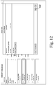
- FIG. 12 is an exemplary screen layout of the graphical user interface illustrating the user control device settings and “switch” mode selection of a user control device;
- FIG. 13 is an exemplary screen layout of the graphical user interface illustrating the user control device “zone” selection
- FIG. 14 is an exemplary screen layout of the graphical user interface illustrating the user control device settings and “scenes” mode selection of a user control device;
- FIG. 15 is an exemplary screen layout of the graphical user interface illustrating the user control device scene selection
- FIG. 16 is an exemplary screen layout of the graphical user interface illustrating the user control device scene selection, with the “All Off” and “All On” scenes selected;
- FIG. 17 is an exemplary screen layout of the graphical user interface illustrating the user control device of FIG. 16 allowing a user to associate the selected scenes with each user interface element;
- FIG. 18 is an exemplary screen layout of the graphical user interface illustrating the user control device of FIG. 16 allowing a user to configure automations for a user interface element;
- FIG. 19 is an exemplary screen layout of an alternative touch-enable embodiment of a user control device including graphical user interface elements
- FIG. 20 is an exemplary screen layout of the graphical user interface illustrating configuration of a touch-enabled user control device
- FIG. 21 is an exemplary screen layout of the graphical user interface illustrating a touch-enabled user control device “zone” selection
- FIG. 1 illustrates an overview of an exemplary wireless device control system 10 , according to the present disclosure.
- the exemplary system 10 generally includes a server, or backend system 12 , one or more site systems 14 , and various clients, also referred to throughout as user computer devices 16 .
- the server system 12 may communicate with the site system 14 and the user computer devices 16 over a wide area network (WAN) such as Internet 20 or a cellular network 22 , and/or via a local area network (LAN).
- WAN wide area network
- LAN local area network
- Each site system 14 may generally include at least one gateway, or base station 24 , lighting controllers 37 , sensors 38 , user control devices 43 , and a mesh network 28 , or other local wireless network, that facilitates communication among site system 14 .
- the gateway 24 serves as the manager/coordinator for site system 14 and mesh network 28 , and provides connectivity to server system 12 .
- the lighting controllers 37 may include an actuator providing dimming and/or on/off control for light fixtures 40 .
- User control device 43 such as a touch-screen or wall dimmer, may be associated with one or more controllers 37 to provide user selection of a desired lighting effect, for example, on/off, dimming, and/or scene selection.
- Sensors for example, an occupancy sensor 38 or a daylight harvester, can be used to provide automations for the site system 14 , including for example, a change to the lighting effect provided by the user control device 43 depending on the state of the sensor 38 .
- FIG. 2 is a more detailed illustration of an exemplary wireless device control system 10 , according to the present disclosure.
- exemplary site systems 14 may include all or portions, including indoor and/or outdoor portions, of a home, business, parking garage, street, worksite, or other location that include a predefined set of components, such as electrical devices or circuits, including, for example, light fixtures, to be monitored or controlled.
- the server system 12 may include one or more servers, or computers 18 including typical computer components, such as a processor, memory, storage, display, network interface, and input/output device, for example.
- the processor, or processors may execute unique sets of instructions, which may be implemented as computer readable program code, stored in memory or storage, such that the server system 12 is configured as a special purpose system.
- hardware, software, and particular sets of instructions may transform the server system 12 , or portions thereof, into a lighting control server system, as described herein.
- the server system 12 may also include any combination of computer hardware and software that facilitates communication with the site systems 14 and user computer devices 16 , and performance of the functions described herein.
- all or portions of the server system 12 may be cloud-based virtual servers, including a virtual private cloud-based service. That is, for example, the one or more servers 18 of the server system 12 may reside on the Internet, for example, rather than on a local computer.
- the server system 12 may be remote from the site systems 14 and/or the user computer devices 16 .
- Digi® Device Cloud offered by Digi® International, Inc., is a public cloud platform for device network management that may be used for all or portions of the server system 12 .
- the server system 12 may communicate with the site systems 14 and the user computer devices 16 over a wide area network (WAN), such as the Internet 20 or a cellular network 22 , and/or via a local area network (LAN), for example.
- WAN wide area network
- LAN local area network
- Cellular communication may be quicker to set-up, more secure and/or more reliable than other available communications means, such as an installation site's broadband internet connection.
- embodiments of the present disclosure are able to keep out of the organization's corporate network, which can assist in mitigating accidental creation of back doors through firewalls and into the user's corporate network that could potentially be used to create a security breach in the organization's corporate network.
- Each site system 14 may generally include at least one gateway, or base station, 24 , and one or more wireless devices 26 , or device nodes, which are configured to communicate over a mesh network 28 , or other similar local wireless network.
- the gateway 24 may include a communications module 30 that facilitates communication between the mesh network 28 , or other wireless network, and the WAN network, such as the Internet 20 or a cellular network 22 . As such, the gateway 24 can facilitate communication between the devices 26 of the site system 14 and the server system 12 .
- the gateway 24 may also include an operations module 32 for processing and/or communicating instructions (e.g., to devices 26 ) received from the server system 12 , as will be described in greater detail below.
- the operations module 32 may also receive and/or process information from the devices 26 . That is, the gateway 24 may run applications locally while also interfacing across the mesh network 28 for WAN connectivity to the server system 12 .
- An exemplary gateway device may be, for example, the XBee® Zigbee® Gateway provided by Digi® International, Inc, configured as a coordinator.
- Each device 26 may include a communications module 34 , facilitating communication between the device 26 and the gateway 24 over a local wireless network, such as the mesh network 28 .
- the devices 26 may each include a radio transceiver, such as a XBee® radio module for communicating using the ZigBee® protocol, which is related to IEEE standards, including 802.15.4.
- the devices 26 may also include at least one control module 36 for facilitating interaction between the device 26 and an associated electrical component, such as, for example, an electrical circuit.
- Devices 26 may also each be configured to act as a router or end device, such that it can also forward messages to other devices 26 and/or the gateway 24 .
- Each site 14 may include a variety of different devices 26 managed by the gateway 24 and connected to the mesh network 28 .
- a site 14 may include lighting controllers 37 , sensors, such as occupancy sensors, 38 , daylight harvesters, and user control devices, such as touchscreens and wall dimmers, 43 .
- Controllers 37 may additionally or alternatively provide a power usage measurement, and may be configured to act an event trigger by detecting voltage and/or current to determine the state of a device, such as, for example, a room light switch or a light fixture having its own motion sensor, or other sensor, to activate it.
- Sensors 38 that are part of the system 10 may be configured to detect and report the state of motion sensors, for example occupancy/vacancy sensors, while daylight harvesters may include a light sensing circuit for measuring light and reporting measurements and other data to the system 10 .
- Each of the user computer devices, or clients, 16 may include a computing device, such as, for example, a personal computer, laptop computer, netbook computer, tablet device, mobile device, portable electronic device (PED), smart device, or cell phone configured to communicate with the server system 12 via WAN 20 or 22 , or possibly with the gateway 24 , for example, via mesh network 28 , to permit a user 42 to configure, monitor, and/or control devices 26 for a particular site system 14 . That is, a user 42 may access a control program, or control logic, on the server system 12 through an appropriate user interface, such as a graphical user interface 1000 , using user computer device 16 , which may have web-browsing abilities or may have a control application installed thereon.
- a computing device such as, for example, a personal computer, laptop computer, netbook computer, tablet device, mobile device, portable electronic device (PED), smart device, or cell phone configured to communicate with the server system 12 via WAN 20 or 22 , or possibly with the gateway 24 , for example, via mesh network
- a web page may be loaded in a web browser of one of the client devices 16 . That is, one of the servers 18 may be or may include a web server for delivering web content to the user 42 through one of the user computer devices 16 described above. Thereafter, the user 42 may be provided with an option of registering for or accessing an account.
- URL Uniform Resource Locator
- the system 10 or, more specifically, the server system 12 may include a plurality of modules useful in carrying out the control and other strategies disclosed herein.
- the server system 12 may include or utilize functionality expressed with reference to an organization account registration module 44 , a user manager module 46 , a device manager module 48 , and a communications module 50 , to name a few.
- modules as used herein, is for ease of explanation, rather than limitation, and is intended to represent certain related aspects or functionality of the wireless device control system 10 .
- Each of the modules may represent a set of computer instructions, or computer readable program code, representing processes for performing specific tasks of the wireless device control system 10 . The tasks may be performed using a processor, or processors, and may require the access or manipulation of data stored in a data repository 52 .
- the account registration module 44 may facilitate the creation of accounts for organizations and/or users, such as users 42 , within the system 10 .
- the registration module 44 may be used to collect data input by users 42 and/or authorized administrators and/or customer service representatives accessing the wireless device control system 10 through one of various user computer devices 16 .
- the various user computer devices 16 may include any suitable electronic communication devices and/or workstations, such as, for example, personal computers, laptop computers, netbook computers, tablet devices, mobile devices, PEDs, smart devices, and cell phones, as mentioned above.
- the account registration module 44 may be used to collect various information, including, for example, personally identifiable information, such as, for example, name, address, and phone number.
- the user manager module 46 may include and/or implement rules pertaining to the various users 42 , or user types, of the system 10 . For example, when one of the users 42 is registered, a user profile including user credentials, such as a username and password, may be created for the user 42 and stored in the data repository 52 . The user manager module 46 may be configured to ensure that each user 42 , as identified using the unique credentials, is provided with appropriate access and/or capabilities with regard to the system 10 , as will be discussed in greater detail below. For example, the user manager module 46 may include an association of each user 42 to one or more sites, and may define appropriate permissions for each user 42 relative to respective organization and/or respective site systems 14 .
- the wireless device control system 10 or, more specifically, the server system 12 may include a database management system including one or more databases, such as data repository 52 .
- the data repository 52 may store data, including the account and user data described above and installation and configuration data for site system 14 , useful in carrying out the strategies disclosed herein.
- the data repository 52 is illustrated as a component within the server system 12 , it should be appreciated that the server system 12 may include any number of separate components or systems, including separate database(s), configured to communicate with one another in a manner consistent with the teachings disclosed herein.
- the device manager module 48 may provide the main functionality of the server system 12 . For example, after account registration is completed and appropriate organizations and/or users are established in the system 10 , the device manager module 48 may be programmed and/or configured to permit users 42 to remotely control and manage specific associated site systems 14 . The device manager module 48 may also monitor and process data from the data repository 52 , and/or acquired data, to facilitate identification configuration, monitoring, and control of the site systems 14 , as will be described below. According to a specific example, the device manager module 48 may receive control information from users 42 via user computer devices 16 , store the information in the data repository 52 , and mirror the information to the appropriate gateway 24 for implementation. According to some embodiments, the data repository 52 may be initially populated with at least some default control data.
- devices 26 of the wireless control system 10 and associated site lighting fixtures 40 may be controlled, monitored, and managed by users 42 , via user computer devices 16 and user control devices 43 .
- devices 26 can act as actuators, causing changes in the environment (e.g., turning lights on or off), user controls, detecting and responding to user interactions, and/or sensors, detecting and/or responding to some input from the environment, such as movement or light, at the respective sites.
- some exemplary devices 26 are described further below and can include user control devices 43 , occupancy/vacancy and other condition sensors 38 , daylight harvesting sensors, and lighting controllers 37 . Standard color coding of wires is used in some embodiments to facilitate ease of installation by electrical technicians.
- exemplary user control devices 43 e.g. mechanical and touch-activated interfaces such as wall dimmer switches and touchscreens, reside at the site 14 , for example, mounted to or recessed within a wall at a convenient location for the areas and zones controlled by the device.
- the user control device 43 may communicate directly with and control the devices 26 of the site system 14 via the mesh network 28 , or communicate with the gateway 24 .
- lighting effects such as on/off or dimming control of one or more controllers 37 associated with a user control device 43 may utilize transmission of messages by device 43 addressed to specific controllers 37 .
- lighting effects such as scene control may utilize transmission of a messages by device 43 addressed to the gateway 24 indicating the user interaction with device 43 and/or the desired scene, resulting in gateway 24 initiating control of appropriate controllers 37 .
- Directly communicating through the mesh network 28 in addressing the devices 26 will reduce latency that might otherwise occur if the user 42 is accessing the devices 26 through the WAN 20 or 22 and through the gateway 24 , as described above.
- the user control device 43 may additionally include a radio module 746 ( FIG. 3 ), such as an XBee® radio module, for example, XBP24CZ7 available from Digi International of Minnetonka, Minn., for communicating using the ZigBee® protocol, as described above, and may serve as a repeater for the mesh network 28 .
- the user control device 43 may include an integrated radio module, or may include an external radio module. If configuration or control of one or more devices 26 is affected from the user control device 43 , the gateway 24 and ultimately the server system 12 and the user interface on a user computer device 16 may be updated accordingly with the new configuration and/or status of the devices 26 , either by the user control device 43 or by the devices 26 themselves.
- a user control device 43 is a dimmer switch 700 .
- the dimmer switch 700 may include a rocker switch 706 with two programmable user interface (e.g. pressure or mechanically activated) elements, 726 and 728 .
- two user interface elements are shown and described, it should be appreciated that a dimmer switch 700 and other forms of user control devices 43 may include more or less than two user interface elements and the additional design characteristics described herein are not intended to be limiting.
- the illustrated embodiment of the exemplary dimmer switch 700 includes a housing/enclosure 724 which can be recessed in a wall-mounted electrical box similar to a common household single-gang light switch.
- the mounting plate 712 and faceplate bracket 704 secure the dimmer switch 700 to the wall surface or electrical box and are covered by the faceplate 702 .
- the main electrical components providing the functionality of the dimmer switch 700 are the control board 718 , to provide a processor 740 and the functions of the radio module 746 as described above, and the power supply board 722 , including for example an AC/DC power supply module 750 .
- Processor 740 may be, for example, an MSP430 microcontroller available from Texas Instruments of Dallas, Tex.
- the dimmer switch 700 may also include external memory, for example CAT24C128 I2C serial EEPROM available from ON Semiconductor of Phoenix, Ariz., to provide additional memory, including, for example, to provide a rollback copy of firmware during firmware updates of the dimmer switch.
- external memory for example CAT24C128 I2C serial EEPROM available from ON Semiconductor of Phoenix, Ariz., to provide additional memory, including, for example, to provide a rollback copy of firmware during firmware updates of the dimmer switch.
- the rocker switch 706 may be configured to perform various different functions depending on the user interaction with the rocker switch, for example, the length and/or number of times a user interface element 726 or 728 is depressed.
- the dimmer switch 700 may be configured such that pressing one user interface element, for example, upper element 726 , closes momentary contact switch 714 ( FIGS. 3 and 7 ), while pressing the second user interface element for example, lower element 728 , closes a second momentary contact switch 716 .
- pressing the same user interface elements two or more times within a predetermined amount of time, or pressing and holding the element may initiate a different lighting effect of the same or a different lighting controller 37 , for example, dimming one or more lighting devices 40 up or down for the duration the element is pressed.
- Other configurations of the user interface elements may include, but are not limited to, initiating certain behaviors associated with schedules, automations, or scenes for individual devices 26 or groupings of devices within specific areas and zones. These various combinations of lighting effects and/or behaviors can be programmed, or virtually mapped, by a user 42 through a user computer device 16 , or more specifically through the graphical user interface 1000 (e.g., FIG. 11 ) of the user computer device 16 .
- the process of commissioning and virtually mapping user control devices 43 is illustrated in FIGS. 4 and 5 and is described in greater detail below.
- the exemplary dimmer switch 700 may include several LEDs 710 , 730 , 732 , and 734 providing indications of various features.
- One or more LED drivers may be used to interface the LEDs with MCU 740 , for example, TLC59208F I2C Bus LED drivers available from Texas Instruments of Dallas, Tex.
- Dimming LEDs 710 FIGS. 3 and 6 ) which can be seen by a user illuminating from the rocker frame 708 , for example, via optical pipes 711 , will illuminate based upon the configuration of the dimmer switch 700 , user actuation of the rocker 706 , and optionally, confirmation of the status of the desired control via controller 37 and/or gateway 24 .
- the upper ten LEDs 710 along the right side of rocker switch 706 are green LEDs and have variable illumination patterns which are generally representative of the mode and status of the dimmer switch 700 and/or user actuation of the rocker 706 .
- a power/indicator LED 732 is a white LED located at the bottom right and indicates the device 43 is powered and can also provide other indications, for example, flashing, upon selection of the device 43 for self-indication, for example, by user 42 via graphical user interface 1000 .
- the ten variable dimming LEDs 710 will illuminate such that a user is able to view the contemporaneous dim level.
- a user increases the power level from 0% to 100%, for example, by pressing and holding the upper user interface element 726 , one additional dimming LED will illuminate from the lower end of the dimmer switch 700 upward for each power increase of 10% until all ten dimming LEDs 710 are illuminating once the power level reaches 100%.
- dimmer switch 700 being operated in dimming mode wherein the power level is 30%, wherein the lowest three of the variable dimming LEDs 710 are illuminated.
- Additional examples of configurable or nonconfigurable control functionality associated with various user interactions with user control elements that may be incorporated into dimmer switch 700 include: touch and release of the bottom element 728 turns off and stores the prior dim level setting; when off, touch and release of the top element 726 turns on and restores the dim level to the stored dim level; double tap of the top element 726 or bottom element 728 sets the dim level to the maximum or minimum, respectively; and press and hold of the top element 726 or bottom element 728 slowly increases or decreases the dim level until released.
- the ten variable dimmer LEDs 710 may illuminate differently when the dimmer switch 700 is operated in scene selection mode. More specifically, when the upper user interface element 726 is pressed, the five upper dimmer LEDs 710 may illuminate continuously or for a predefined period of time before turning back off indicating selection of a scene associated with the upper element 726 . Alternatively, when the bottom user interface element 728 is pressed, the five lower dimmer LEDs 710 may illuminate continuously or for a predefined period of time before turning back off.
- FIG. 9 illustrates a dimmer switch 700 being operated in scene selection mode wherein the upper interface element 726 has been pressed. Additionally or alternatively, one or more of the user interface elements 726 and 728 may be used to selectively index through and select from a series of different scenes, for example, several different scenes, providing selection from among more scenes than there are elements associated with the dimmer switch 700 .
- the device may be selectively configured to control both the power/dim settings for one or more control devices 37 AND scene control selection. For example, use of a particular user interactions with a user control element, use of a particular user control elements, or satisfaction of conditions for a particular automations (discussed further below) could be used to distinguish between power/dim control and scene control selection.
- the exemplary dimmer switch may also include a network connectivity status indicator 730 and plurality of network signal LEDs 734 which can be seen by a user during installation and hidden during subsequent use.
- the network signal LEDs 734 are blue LEDs located on the control board 718 and are covered by the faceplate 702 upon completion of installation.
- the plurality of network LEDs 734 may be provided to function as a signal strength indicator, providing a visual indication of signal strength to, for example, the nearest device 26 in the mesh network 28 .
- three illuminated LEDs may represent strong signal strength, two illuminated LEDs may represent acceptable signal strength, and one illuminated LED may represent unacceptable signal strength.
- the network connectivity status indicator 730 may include a multicolor LED. For example, illumination of a green LED may indicate device 43 is joined with mesh network 28 , for example, also registered with and recognized by gateway 24 . A red LED of status indicator 730 may indicate the device 43 is not joined with mesh network 28 .
- a user control device 43 is a touchscreen device 701 ( FIG. 2 ), such as a tablet computing device, that functions like one of the user computer devices 16 , having a user interface application or software installed directly thereon, facilitating the system configuring, monitoring, and controlling as described herein, for example, the exemplary user interface screen as shown in FIG. 19 that provides configurable touch-activated user interface elements 1010 , 1012 , and 1014 .
- the touchscreen control device 701 may include other radio modules, as tablet computing devices typically do, that are disabled to limit communication to the mesh network, which increases security of the wireless device control system 10 .
- the mesh network 28 is the only wireless communications available to the user control device 43 , a problem arises in how to install and updating software for the device, and, in particular, the user interface application.
- a user interface application can be deployed to the user control device 43 via server 12 , WAN 20 or 22 , gateway 24 , and mesh network 28 .
- An exemplary lighting controller 37 may switch mains power to circuits, such as, for example, circuit 41 of FIG. 2 , as well as provide a dimming interface for dimmable drivers and ballasts.
- the controller 37 may provide a 0-10V dimming interface.
- the remotely controlled controller device 37 may, thus, provide ON/OFF control, as well as dimming, for light fixtures installed on the same circuit.
- mains power broadly refers to power delivered to a site or location, such as a house or building, from a utility company, and power distributed throughout the site or location, such as from a circuit breaker to a number of branch circuits, for example, 120 VAC power.
- devices 26 may be configured to provide a power loss message/notification.
- these devices 26 are configured to, upon detection of the loss of mains power, send a packet to the gateway 24 indicating such. To do so, capacitive circuits of the devices 26 maintain sufficient power to send this last message to the gateway 24 , indicating power loss.
- the dimmer switch 700 power loss detection circuit 744 can provide such detection and sufficient capacitive storage to provide momentary power for the processor 740 and the radio module 746 to send a power loss message. If the gateway 24 does not receive this message, it can be presumed that any loss of communication from the device 26 is due to a loss of reception rather than a loss of power.
- AC power loss can be detected by the power loss detection circuit 744 in various ways known in the art, including in two illustrative ways.
- AC power loss is detected by monitoring zero voltage crossing of the AC supply power of the device 26 .
- the processor receives the AC power line and signals through the power monitor at the AC input pins and enable the processor to measure instantaneous AC voltage.
- the processor triggers an AC power loss notification upon an absence of zero crossings detected over a specified period of time, for example, two or more zero voltage crossings during the period of time expected for 60 Hz AC power, for example about 20 msec.
- the second way AC power loss is detected or confirmed is by determining that DC voltage at a first DC voltage output is lost.
- the device 26 processor can include an input/output port coupled to the first DC voltage output to monitor whether the voltage level at a junction between a first DC stage and a second DC stage reflects that AC power is provided (if the first DC voltage level is detected) or if AC power is lost (if a lower and/or declining DC voltage level is detected).
- a capacitor is coupled across the node between the output and the anode of the diode and ground. Upon loss of AC power, the capacitor will discharge through the associated resistive voltage divider, which also provides a voltage detection level across the capacitor that is scaled appropriately for the port of the processor.
- the port As an output port, set the output low, for example, for a few milliseconds, then set the port to input in order to catch the rising side of the port threshold rapidly if the voltage across the capacitor is already low.
- the port is always an output and the capacitor is discharging, it can take about 100 milliseconds or longer to detect a low voltage state at the descending side of the port threshold.
- An additional feature is an optional power supply split of the controller circuitry powered by the second DC stage so that upon detection of power loss, power can be disconnected from part of the controller circuit and power from a capacitive supply can continue to power only the portion of the control circuitry needed to transmit a power loss data message.
- At least one gateway such as gateway 24 above, is installed to communicate with devices 26 at a site 14 .
- the gateway 24 serves as the coordinator of and manages the mesh network 28 and communicates with the server system 12 .
- the gateway 24 ultimately controls the devices 26 , with control information mirrored from the server system 12 , with which users 42 and user computer devices 16 directly interact.
- the gateway 24 communicates with the server system 12 via cellular or, in some particular embodiments, machine-to-machine cellular.
- the gateway 24 may be provided with a subscriber identity module (SIM) card for facilitating communication over a cellular network, for example, private, encrypted 3G cellular connection independent of any site networks.
- SIM subscriber identity module
- This connection may be maintained while the gateway 24 is powered on, and, by avoiding the use of an Ethernet, WiFi, or other shared internet connection, may be more secure than alternative communications means, also avoiding providing a possible inadvertent intrusion pathway through a firewall of the site 14 .
- Embodiments for packet routing through mesh network 28 include ad hoc network routing where the shortest path from a device 26 to the gateway 24 is continually updated and used for communications. Still other embodiments utilize source routing where a routing path from a device 26 to the gateway is initially set and remains unchanged until the routing path is updated at a later (typically predetermined) time. Still other embodiments will utilize ad hoc routing when there are a particular number of nodes in the mesh network 28 (e.g., 40 or less) and will utilize source routing when there are a different number of nodes in the mesh network (e.g., >40 nodes).
- FIG. 10 other embodiments of the present disclosure can address illumination latency issues by using a point-to-point (device-to-device) control scheme in which packets containing commands are sent directly from one device 26 to another device 26 , rather than having to route through the gateway 24 , which may sometimes result in appreciable and undesirable delays between user control interaction and changes in lighting effects in the site 14 .
- a user control device 43 associated with the mesh network 28 provides instructions in a messaged addressed directly to the controller 37 for the light fixture 40 .
- the user control device 43 will send the command (e.g., on, off and/or dim) packet directly to the controllers 37 for the light fixtures, i.e., bypassing the gateway 24 , then each controller 37 can send a response to the gateway 24 and the/or the user control device 43 to inform the gateway that the command was received and/or a change in status of the controller (or light fixture) had occurred.
- Other devices such as occupancy sensors 130 and controllers 37 that are configured in site system 14 to control another device 26 can similarly employ point-to-point packet routing and control.
- the gateway 24 communicates via a cellular network
- the gateway 24 is typically installed at a location having a good cellular signal.
- the devices 26 are also typically installed such that they communicate with the gateway 24 , either directly or indirectly (such as through other devices 26 of the wireless mesh network 28 ). With the devices 26 powered on, the installer can ensure that the devices have a “good” signal indication to ensure good communication with gateway 24 , for example, using the indicators 714 and 730 on the dimmer switch 700 . If the signal is unacceptable, the devices 26 may be relocated or additional devices may be added between the particular device 26 and the gateway 24 .
- the hardware may be commissioned, during which the device enters the network and is identified by the server system 12 .
- the devices being mounted and powered on will self-commission, greatly simplifying installation.
- the gateway 24 self-commissions by automatically identifying itself to the device control system 10 and with a user organization account.
- any device 26 e.g., gateway 24 , any device 26 , sensors 38 and/or any user control device 43
- such hardware will self-commission by automatically initiating communications with the server system 12 (which for a device 26 will typically do so by communicating and registering with the gateway 24 which in turn registers the device with server system 12 ) and identifying itself to the server system 12 , which may occur over a cellular telephone network as previously described.
- the devices 26 When the devices 26 are powered on, they can wirelessly and automatically attempt to communicate with the gateway 24 via the mesh network 28 .
- the devices 26 can identify themselves to the gateway 24 and the gateway 24 can inform the server system 12 of the devices 26 (see, e.g., step 414 of FIG. 4 ).
- a proprietary link key may be used to secure communications between the gateway 24 and devices 26 , even during initial commissioning.
- the hardware can be associated with a user organization account for the device control system 10 , which may be accomplished automatically, such as if an account has already been established, or by an administrator of the server system 12 .
- the user need only power on the hardware (typically after mounting and wiring with the light fixtures 40 ) to have the hardware communicate with the server system 12 and have the server system 12 identify which specific device self-commissioned.
- no special training may be required, other than potentially having an electrician's certification depending on local laws, to have one or more devices fully integrated into the network and into an operational system.
- the self-commissioning process speeds the installation process.
- a user without an organization account can have an account established and have the device (e.g., a wireless dimmer switch 700 ) fully integrated into the network within minutes (e.g., less than 1 minute in some embodiments, and less than 5 minutes in other embodiments).
- the device e.g., a wireless dimmer switch 700
- the gateway 24 may be associated with an account, such as, for example, by a user or administrator accessing or creating an account over the Internet.
- a user may call a customer service representative to assist in establishing a user account and/or the commissioning process.
- an interactive voice response system may be integrated with the device control system 10 to assist in the registration and/or commissioning process.
- a gateway identification code for the gateway 24 is typically associated with a particular organization account and site, such as site system 14 .
- the method begins at a START, step 402 , and proceeds to a first step, shown at step 404 , in which registration occurs.
- a user such as one of users 42
- an administrator may register users 42 and create user accounts.
- a gateway such as gateway 24
- the gateway 24 may appear on a user interface, such as a graphical user interface 1000 , of a user device, such as one of the user computer devices 16 .
- Devices 26 may be designed such that upon power up they automatically attempt to register with the gateway 24 after they are powered on, at steps 410 and 412 . That is, when a device 26 such as a user control device 43 is powered on, it wirelessly and automatically attempts to communicate with the gateway 24 . In particular, the device 26 identifies itself to the gateway 24 and the gateway 24 informs the server system 12 of the device 26 , at step 414 .
- the gateway 24 may prevent new devices 26 from using the proprietary link key to join the mesh network 28 unless a customer service representative and/or organization administrator has set the site system 14 and gateway 24 to allow new devices to join, for example, by selecting an “add devices mode” on the graphical user interface 1000 .
- the user 42 may then be able to manage devices 16 through the user interface, at step 416 , as will be discussed below for flowchart 500 for the user control devices 43 .
- Users 42 may have various levels of access and control with regard to a particular site and/or particular device 26 .
- the server system 12 communicates control instructions to the gateway 24 , at step 418 , and the gateway 24 may execute the instructions, at step 420 .
- Updates provided by the user 42 may be forwarded from the server system 12 to the gateway 24 .
- the gateway 24 may receive various information from the device 26 , and may send, or relay, various updates to the server system 12 .
- the method proceeds to an END, at step 422 .
- the device 26 may be managed within a user interface as provided by a user computer device 16 . That is, with continued reference to FIGS. 1-2 , representations, such as, for example, graphical and/or textual representations, of the device 26 may be displayed on a graphical user interface 1000 of one of the user computer devices 16 , as shown for example in FIGS. 11-21 . Additionally, when a user 42 , particularly an organizational administrator, logs into their account, all sites, or site systems 14 , associated with the user 42 may be visible through the user interface.
- entries 1002 representative of actual devices 26 are visible through the user interface and include information, such as unique device identifiers.
- the user 42 may enter additional information about each device 26 , such as a device location, description, and zone, using the user interface.
- a user input such as an indicate selection button 1004 associated with a specific one of the entries 1002 displayed on the graphical user interface 1000 may be actuated, as illustrated in FIG. 12 .
- an indicator on the physical device 26 represented by that entry 1002 may be modified in some predetermined way to assist the user 42 in matching each entry 1002 to the physical device 26 it represents.
- an indicator such as the power indicator LED 732 ( FIG. 8 ) of the dimmer switch 700 , may illuminate using a predetermined duration and/or pattern, or the load (e.g. light fixture 40 ) controlled by the device may be repeatedly switched on/off or dimmed/undimmed.
- An additional and/or alternative device identification may include the user 42 actuating a physical switch or pushbutton, such as pushbutton 720 ( FIG. 8 ) of the exemplary dimmer switch 700 , of one of the devices 26 .
- This actuation may generate a communication sent by the radio module 746 ( FIG. 3 ) of the dimmer switch 700 and be received by the gateway 24 of the site system 14 and communicated, along with the unique device identifier of the selected device 26 , e.g. of the dimmer switch 700 , to the server system 12 .
- this actuation my change a state of a status indicator on the device 26 , for example, one or more LEDs may blink for a period of time or other condition satisfied subsequent to a physical switch being actuated.
- the device entries 1002 as shown in FIG. 11 , or other representation, in the user interface may be changed to identify which device entry 1002 corresponds to the selected device 26 .
- the particular device entry 1002 corresponding to the selected device 26 may be moved up to the top of the list, highlighted, or otherwise indicated, and may be pre-selected in preparation for the user 42 to continue the commissioning process.
- the user 42 may be assisted in adding useful and accurate information about the device 26 via the graphical user interface 1000 .
- the user 42 may begin remotely managing and controlling the devices 26 , for example, by initiating manual actions through a graphical user interface 1000 or creating automations and schedules to be carried out by the server system 12 and/or gateway 24 .
- users 42 may have various levels of access and control with regard to a particular site 14 and/or particular devices 26 .
- the server system 12 communicates control instructions to the gateway 24 (and/or devices 26 via gateway 24 ), and the gateway 24 (and/or devices 26 ) may execute the instructions. Updates provided by the user 42 may be forwarded from the server system 12 to the gateway 24 , and to devices 26 .
- the gateway 24 may receive information from the devices 26 , and may send, or relay, various updates to the server system 12 .
- the devices 26 may accomplish some function, such as detecting changes in the environment or causing changes in the environment. That is, for example, some devices 26 may switch power to a lighting fixture and/or control a dim level of the lighting fixture(s).
- a trim level representing a maximum illumination level of the lighting fixture, may be set or modified through the graphical user interface 1000 .
- a user may set a trim level for a particular light by lowering the maximum illumination level for the light so that a user may not increase the illumination level/output beyond the newly selected maximum level.
- a minimum dim level may be set and/or adjusted through the application user interface.
- the device 26 e.g., an occupancy sensor
- the device 26 can restrict the maximum illumination of the fixture when the sensor detects a person, e.g., when the light is turned on the light illuminates to only 80% of its maximum illumination.
- illumination can be less than 100% when using trim levels
- the wall switch can be configured to indicate the fixture is at 100% illumination while the user interface (cell phone, iPad, etc.) can show the actual illumination level (e.g., 80%).
- each of the devices 26 may be associated with or may correspond to a particular zone.
- a zone may represent an electrical circuit having one or more lighting fixtures installed thereon. Zones may be grouped into areas, which may represent, for example, rooms, locations, or other designated areas of the site 14 . This organization may logically group circuits into common areas to facilitate appropriate monitoring and control.
- FIG. 13 a screen layout depicts the creation of an area and selection of zones to group within the area via an exemplary user interface.
- sunset and sunrise times are used by the system 12 , for example, to control when different “scenes” are configured as depicted in FIGS. 14-16 ; during commissioning of a gateway 24 or later during configuration, a user or administrator enters the zip code where the site system 14 , including the gateway 24 , is located and the server system 12 uses the zip code to determine an approximate latitude and longitude of the site system 14 for sunrise/sunset calculations. Determining the latitude and longitude based on only the zip code and calculating and storing that information at the server system 12 adds an extra layer of security to assist in obscuring the precise physical location of the site system 14 .
- the flowchart 500 of FIG. 5 represents the exemplary method for configuring a user control device 43 , such as the exemplary dimmer switch 700 , of the wireless device control system 10 .
- the method begins at a START, step 502 , and proceeds to a first step, shown at step 504 , for commissioning of the system devices 26 .
- the site system 14 is planned and deployed, and the device 26 is properly commissioned at step 504 (for example, according to flowchart 400 of FIG. 4 )
- the user 42 may begin remotely managing and controlling the device 26 .
- all sites, or site systems 14 , associated with the user 42 may be visible through the graphical user interface 1000 as depicted in step 506 and in the screenshots of FIGS. 11-21 , and particularly the user control devices 43 shown as entries 1002 in FIG. 11 .
- the user 42 may select one of the sites or site systems 14 , wherein entries 1002 representative of connected devices 26 are visible through the graphical user interface 1000 and include information such as unique device identifiers, as shown in FIG. 11 .
- entries 1002 representative of connected devices 26 are visible through the graphical user interface 1000 and include information such as unique device identifiers, as shown in FIG. 11 .
- the user 42 is presented with a set of configurable options specific to the device associated with that entry 1002 . More specifically, if the entry 1002 represents the exemplary wall dimmer switch 700 , the graphical user interface 1000 will present a list of configurable options similar to those shown in FIG.
- FIG. 11 which is based upon the properties and capabilities of the wall dimmer switch 700 , including for example based upon the properties and capabilities of the particular firmware update for the wall dimmer switch 700 .
- the user 42 can select to edit mode and other INFO and CONTROL ZONES and AUTOMATIONS associated with the selected dimmer switch 700 .
- a touchscreen device 701 If a touchscreen device 701 is selected, a customized set of configurable options would be presented by the graphical user interface 1000 at step 508 , for example, INFO, CONTROL ZONES, and CONTROL SCENES selectable for editing as shown in FIGS. 20 and 21 .
- the user 42 can enter into the device settings screen of the selected entry 1002 .
- a user may configure the device mode, for example, “dimmer” mode, “switch” mode, or “scenes” mode, to virtually map to the selected device.
- the mode selection provides a set of general functional features and advantageously allows for one type of physical device to be virtually reconfigured to operate in any one of several different functional operating modes. For example, in “dimmer” mode, the selected wall dimmer switch 700 of FIG.
- this mode can provide ON/OFF control in response to a different user interaction with the user interface elements 726 and 728 , for example, a momentary press and release interaction rather than a press and hold interaction.
- switch mode for the selected wall dimmer switch 700 , a user 42 could assign the user interface elements 726 and 728 to operate only as ON/OFF pushbuttons.
- a user could configure the user interface elements to generate a configurable scene output as described further below. This step also allows a user 42 to virtually actuate the “indicate” function from the graphical user interface 1000 via the “Indicate” pushbutton 1004 .
- the user 42 can select zones, scenes, or other lighting effects to associate with the selected user control device 43 .
- a listing of areas e.g. CONFERENCE and SHOWROOM
- zones within each area e.g. SPOTLIGHTS and CONFERENCE ROOM for the CONFERENCE area
- SPOTLIGHTS and CONFERENCE ROOM for the CONFERENCE area
- one or more zones can be selected to be simultaneously controlled in switch or dimmer mode.
- step 512 the illustrative graphical user interface screen of FIG. 15 will be displayed.
- the displayed scenes available for selection for example, for each area “All Off,” “25%,” “50%,” and “All On,” are those scenes earlier configured for site 14 using user computer device 16 as discussed further below.
- two scenes, “All Off” and “All On,” are selected to be associated with dimmer switch 700 and available to virtually map to user interface elements 726 and 728 .
- step 512 if the selected user control device 43 is a touchscreen device 701 ( FIG. 19 ), then at the graphical user interface screen of FIG. 20 ZONES and CONTROL SCENES can be selected for editing, i.e., selecting the user interface elements, e.g., zone on/off 1010 , zone dimmer sliders 1012 , and scenes selectors 1014 , that will be displayed for touch-activation as shown in FIG. 19 .
- FIG. 21 illustrates a graphical user interface screen for selecting which zones of site 14 to associate with device 701 and provide touch-activated graphical user interface elements for display.
- the scenes e.g. “All Off” and “All On,” can be virtually mapped to the available user interface elements, e.g., “top” user interface element 726 and “bottom” user interface element 728 , as shown to the right of the selected scene.
- the list of scenes to the left can be reordered to change the virtual mapping with the user interface elements 726 and 728 to the right by touching and dragging a particular scene to reposition it in the list, thereby changing the virtual mapping to what is then displayed.
- the list of available elements to the right for virtual mapping will be automatically populated to be shorter or longer in accordance with the particular device as recognized by the gateway 24 and/or the remote server system 12 .
- automations can be optionally associated with one or more user interface elements of the user control device 43 .
- Automations are behaviors performed in accordance with a set of rules and based on conditions defined within the rules and are discussed further below. For example, an illustrative example for an automation associated with the dimmer switch 700 selected to operate in scene mode is to condition the scene selected based on the time of day and day of week.
- the upper user interface element 726 is automated to select the “50%” scene and the lower user interface element 728 is automated to select the “25%” scene
- the upper element 726 is automated to select the “All On” scene
- the lower element 728 is automated to select the “All Off” scene.
- Other automations based on other conditions, including those discussed further below may also be used as part of the association and virtual mapping for user control devices 43 , including the dimmer switch 700 and touchscreen device 701 .
- step 518 the configurations selected are saved to the server system 12 , gateway 24 , and for some embodiments, the user control device 43 .
- step 520 the process of flowchart 520 is completed.
- the gateway 24 may then be decommissioned or disconnected from the site system 14 . More specifically, the gateway 24 may either be powered off and removed from the site system 14 or disabled from network connectivity and the user control device 43 may then communicate and execute configured lighting effects independently and without communication to or from the gateway 24 . In this mode of operation, the user control device 43 may still communicate directly with multiple devices 26 of the site system 14 to accomplish the configured lighting effects.
- the gateway 24 may be disconnected from the server system 12 and the site system 14 may operate independent of any communication or device outside of the site system. For example, gateway 24 may continue to operate as the controller of the mesh network 28 ; however, the gateway 24 may not require ongoing communication with the server system 12 to operate.
- the WAN 20 , 22 is used for commissioning and configuration, but not used to communicate between gateway 24 and server system 12 for subsequent operation of the site system 14 .
- the illustrative mesh network 28 uses ZigBee, an open global standard for low-power, low-cost, low-data-rate, wireless mesh networking based on the IEEE 802.15.4 standard.
- ZigBee allows the transmission of data over long distances by passing the data through a mesh network of intermediate nodes to reach more distant ones. It represents a network layer above the 802.15.4 layers to support advanced mesh routing capabilities.
- the ZigBee specification is developed by a growing consortium of companies that make up the ZigBee Alliance.
- ZigBee Smart Energy Standard ZigBee Profile: 0x0109, Revision 19, Version 1.2a, Document 07-5356-19, incorporated by reference herein in its entirety, describes device high-level communication protocols used to create personal area networks with small, low-power digital radios, including the installation and use of security keys.
- Each ZigBee network must be formed by one, and only one, coordinator, which is the gateway 24 in the illustrative embodiment of control system 10 .
- the devices 26 of the wireless device control system 10 can be a router type or an end type device; however, for typical installations, most devices 26 will be a router.
- a router is a full-featured ZigBee node and perform various functions including join existing networks and send, receive, and route information (routing involves acting as a messenger for communications between other devices that are too far apart to convey information on their own).
- a network may have multiple router devices.
- An end device is essentially a reduced version of a router. The end device cannot act as messenger between any other devices but is capable of receiving messages intended for it and transmitting messages initiated by it.
- Automations also referred to as behaviors, may represent sets of rules, or if/then conditions that bind input events into output events or actions.
- An action is a command that is enacted when a condition is fulfilled, for example, commanding a zone state or commanding a scene.
- An action can also be a system notification provided via a user interface of a user computer device 16 .
- some input events satisfying a condition/event that triggers an automation may include power measurements, such as voltage or wattage, exceeding or falling below a predetermined threshold, and the detection that particular circuits have opened or closed, such as a controller's zone being switched on with a wall switch, and schedules, as discussed further below, for example, expiration of a delay time or a particular time of the day and/or day of the week.
- some exemplary conditions may include motion detection and motion timeout expiration.
- Some conditions pertaining to daylight harvesters may include detected light levels exceeding or falling below predetermined thresholds.
- Exemplary actions responsive to those exemplary behaviors may include switching a device and/or zone on or off, setting or changing a dim level, and activating a particular scene, which is described further above for user control devices. Some actions may trigger upon the satisfaction of multiple conditions. For example, a certain condition may automatically occur if a particular sensor state change is detected AND it is within a certain time period of the day. Automations can save energy, for example, by switching off particular zones when the occupancy sensor 130 detects expiration of a motion timeout period, or dimming or switching off particular zones responsive to light levels detected by the daylight harvester.
- An automation configuration view of the graphical user interface 1000 is depicted in FIG. 18 and includes a list of devices having the associated conditions. The addition of conditions to a device is shown in in FIG. 24C .
- Scenes describe a set of state change requests, such as an area or set of zones and each of their dimming level presets. Scenes, which are essentially a group of light settings, may be activated manually or at specific times defined in a schedule. For example, a “presentation mode” may have some lights on, some lights off, and some lights dimmed to 50%. Illustrations of scene configuration views on the graphical user interface 1000 are shown in screen layouts of FIGS. 14-17 .
- Schedules allow you to set the lights to come on and off at specific times with optional repetition.
- a schedule can define a week's worth of events. Schedules can apply to one or more devices, zones or areas. An event could be a scene selection. Time segments throughout the day may be associated with different scenes.
- control for automations, scenes, and schedules reside in the gateway, so loss of connection to the cellular network (and, therefore, the server system) does not affect use of these functions.
- a dimmer switch can have an on/off/dim as a primary function, but may also have automations such as (i) once the light is on, the light dims or goes off after a particular time, or (ii) after the light is turned off, the lights in the parking lot turn on for a particular time.
- items (i) and (ii) can be automations whose functionality resides at the gateway.
Abstract
Description
Claims (20)
Priority Applications (4)
| Application Number | Priority Date | Filing Date | Title |
|---|---|---|---|
| US16/694,468 US10855488B2 (en) | 2014-08-11 | 2019-11-25 | Scheduled automation associations for a lighting control system |
| US17/109,032 US11398924B2 (en) | 2014-08-11 | 2020-12-01 | Wireless lighting controller for a lighting control system |
| US17/814,513 US11722332B2 (en) | 2014-08-11 | 2022-07-23 | Wireless lighting controller with abnormal event detection |
| US18/366,660 US20230379185A1 (en) | 2014-08-11 | 2023-08-07 | Wireless lighting control system with independent site operation |
Applications Claiming Priority (6)
| Application Number | Priority Date | Filing Date | Title |
|---|---|---|---|
| US201462035558P | 2014-08-11 | 2014-08-11 | |
| US14/823,560 US9883567B2 (en) | 2014-08-11 | 2015-08-11 | Device indication and commissioning for a lighting control system |
| US201562257908P | 2015-11-20 | 2015-11-20 | |
| US15/357,900 US10085328B2 (en) | 2014-08-11 | 2016-11-21 | Wireless lighting control systems and methods |
| US15/492,373 US10531545B2 (en) | 2014-08-11 | 2017-04-20 | Commissioning a configurable user control device for a lighting control system |
| US16/694,468 US10855488B2 (en) | 2014-08-11 | 2019-11-25 | Scheduled automation associations for a lighting control system |
Related Parent Applications (1)
| Application Number | Title | Priority Date | Filing Date |
|---|---|---|---|
| US15/492,373 Continuation US10531545B2 (en) | 2014-08-11 | 2017-04-20 | Commissioning a configurable user control device for a lighting control system |
Related Child Applications (1)
| Application Number | Title | Priority Date | Filing Date |
|---|---|---|---|
| US17/109,032 Continuation US11398924B2 (en) | 2014-08-11 | 2020-12-01 | Wireless lighting controller for a lighting control system |
Publications (2)
| Publication Number | Publication Date |
|---|---|
| US20200092974A1 US20200092974A1 (en) | 2020-03-19 |
| US10855488B2 true US10855488B2 (en) | 2020-12-01 |
Family
ID=59387387
Family Applications (6)
| Application Number | Title | Priority Date | Filing Date |
|---|---|---|---|
| US15/492,373 Active US10531545B2 (en) | 2014-08-11 | 2017-04-20 | Commissioning a configurable user control device for a lighting control system |
| US16/218,123 Active US10398010B2 (en) | 2014-08-11 | 2018-12-12 | Power loss detection for a lighting control system |
| US16/694,468 Active US10855488B2 (en) | 2014-08-11 | 2019-11-25 | Scheduled automation associations for a lighting control system |
| US17/109,032 Active US11398924B2 (en) | 2014-08-11 | 2020-12-01 | Wireless lighting controller for a lighting control system |
| US17/814,513 Active US11722332B2 (en) | 2014-08-11 | 2022-07-23 | Wireless lighting controller with abnormal event detection |
| US18/366,660 Pending US20230379185A1 (en) | 2014-08-11 | 2023-08-07 | Wireless lighting control system with independent site operation |
Family Applications Before (2)
| Application Number | Title | Priority Date | Filing Date |
|---|---|---|---|
| US15/492,373 Active US10531545B2 (en) | 2014-08-11 | 2017-04-20 | Commissioning a configurable user control device for a lighting control system |
| US16/218,123 Active US10398010B2 (en) | 2014-08-11 | 2018-12-12 | Power loss detection for a lighting control system |
Family Applications After (3)
| Application Number | Title | Priority Date | Filing Date |
|---|---|---|---|
| US17/109,032 Active US11398924B2 (en) | 2014-08-11 | 2020-12-01 | Wireless lighting controller for a lighting control system |
| US17/814,513 Active US11722332B2 (en) | 2014-08-11 | 2022-07-23 | Wireless lighting controller with abnormal event detection |
| US18/366,660 Pending US20230379185A1 (en) | 2014-08-11 | 2023-08-07 | Wireless lighting control system with independent site operation |
Country Status (1)
| Country | Link |
|---|---|
| US (6) | US10531545B2 (en) |
Cited By (1)
| Publication number | Priority date | Publication date | Assignee | Title |
|---|---|---|---|---|
| US11672070B2 (en) | 2021-04-12 | 2023-06-06 | Appleton Grp Llc | Providing industrial network reliability using luminaires |
Families Citing this family (27)
| Publication number | Priority date | Publication date | Assignee | Title |
|---|---|---|---|---|
| US10075334B1 (en) * | 2012-04-11 | 2018-09-11 | Google Llc | Systems and methods for commissioning a smart hub device |
| US9198204B2 (en) | 2012-04-11 | 2015-11-24 | Google Inc. | Apparatus and method for seamless commissioning of wireless devices |
| US10609791B2 (en) * | 2015-10-22 | 2020-03-31 | Signify Holding B.V. | Lighting system optimized for cost reduction |
| US11437814B2 (en) * | 2016-07-05 | 2022-09-06 | Lutron Technology Company Llc | State retention load control system |
| EP3482533B1 (en) | 2016-07-05 | 2021-06-30 | Lutron Technology Company LLC | State retention load control system |
| KR102426400B1 (en) * | 2017-08-23 | 2022-07-29 | 삼성전자주식회사 | Configuration Method of Action for external device and electronic device supporting the same |
| CA3080164A1 (en) * | 2017-10-26 | 2019-05-02 | Racepoint Energy, LLC | Intelligent lighting control system multi-way apparatuses, systems, and methods |
| US20190394817A1 (en) * | 2018-06-21 | 2019-12-26 | Ecolink Intelligent Technology, Inc. | Method and apparatus for home monitoring and control system setup |
| TWI671661B (en) * | 2018-09-17 | 2019-09-11 | 王啟祥 | System for changing device control interface according to controlled device function |
| US11464096B2 (en) | 2018-09-28 | 2022-10-04 | Leviton Manufacturing Co., Inc. | Dimmer with improved noise immunity |
| CN113812213A (en) * | 2019-03-08 | 2021-12-17 | 路创技术有限责任公司 | Debugging and controlling load control device |
| US11425810B1 (en) | 2019-03-20 | 2022-08-23 | Neopod LLC | Smart lighting control system |
| US11082521B2 (en) * | 2019-05-24 | 2021-08-03 | California Eastern Laboratories, Inc. | Single source of information apparatuses, methods, and systems |
| FI3994910T3 (en) * | 2019-07-01 | 2023-06-13 | Signify Holding Bv | Automatic power-on restart system for wireless network devices |
| EP3790363A1 (en) * | 2019-09-06 | 2021-03-10 | Tridonic GmbH & Co. KG | Wireless commissioning system for dali devices |
| US11234295B2 (en) * | 2019-10-07 | 2022-01-25 | Comcast Cable Communications, Llc | Wireless network device configured for adjustable positioning |
| US11537703B2 (en) * | 2019-10-11 | 2022-12-27 | Moon River Investments, Llc | GFI tripped circuit detection and wireless notification systems and methods |
| US10869371B1 (en) * | 2019-12-23 | 2020-12-15 | Eaton Intelligent Power Limited | Configuring color of indicator LED using single wire two-way communication |
| US10798796B1 (en) * | 2019-12-23 | 2020-10-06 | Eaton Intelligent Power Limited | Dimmer switch system with single wire two-way communication architecture |
| US11553580B2 (en) * | 2020-05-07 | 2023-01-10 | FJP Solution LLC | Connectors and wireless controllers for wired lighting systems |
| WO2021236150A1 (en) * | 2020-05-21 | 2021-11-25 | Leviton Manufacturing Co., Inc. | Prediction and recovery of zero-crossing information and selective control signal pulse duration |
| US11903105B2 (en) | 2020-05-21 | 2024-02-13 | Leviton Manufacturing Co., Inc. | Prediction and recovery of zero-crossing information and selective control signal pulse duration |
| WO2021236174A1 (en) | 2020-05-21 | 2021-11-25 | Leviton Manufacturing Co., Inc. | Switching control in electrical load controllers |
| US11743996B1 (en) * | 2020-09-18 | 2023-08-29 | Lutron Technology Company Llc | Load control system comprising linear lighting fixtures |
| US11522767B2 (en) | 2020-10-22 | 2022-12-06 | Bank Of America Corporation | System for real-time imitation network generation using artificial intelligence |
| US11871493B2 (en) | 2021-06-04 | 2024-01-09 | Leviton Manufacturing Co., Inc. | Timing adjustments for accurate zero-crossing determination |
| RU207761U1 (en) * | 2021-07-30 | 2021-11-15 | Общество с ограниченной ответственностью «ВОСТОКЭНЕРГОСЕРВИС» | Combustion controller OUG-KG3LED |
Citations (393)
| Publication number | Priority date | Publication date | Assignee | Title |
|---|---|---|---|---|
| JPS4625697Y1 (en) | 1968-05-31 | 1971-09-04 | ||
| US5166887A (en) | 1988-03-31 | 1992-11-24 | Square D Company | Microcomputer-controlled circuit breaker system |
| US5283905A (en) | 1991-06-24 | 1994-02-01 | Compaq Computer Corporation | Power supply for computer system manager |
| US5357361A (en) | 1991-07-15 | 1994-10-18 | Nishizawa Junichi | Discriminating light-emitting optical apparatus |
| CN1119888A (en) | 1993-03-25 | 1996-04-03 | 巴布考克和威尔考克斯公司 | Fluidized bed reactor with particle return |
| US5598042A (en) | 1993-09-22 | 1997-01-28 | The Watt Stopper | Moveable desktop load controller |
| US5623172A (en) | 1995-07-03 | 1997-04-22 | Leviton Manufacturing Co., Inc. | Two wire PIR occupancy sensor utilizing a rechargeable energy storage device |
| CA2236569A1 (en) | 1996-09-03 | 1998-03-12 | Philips Electronics N.V. | Method for installing a wireless network |
| CA2249423A1 (en) | 1997-01-23 | 1998-07-30 | Simon Hendrik Anton Begemann | Luminaire |
| US5905442A (en) | 1996-02-07 | 1999-05-18 | Lutron Electronics Co., Inc. | Method and apparatus for controlling and determining the status of electrical devices from remote locations |
| EP0923274A2 (en) | 1997-12-10 | 1999-06-16 | Siemens Aktiengesellschaft | Universal dimmer and process for dimming |
| CN2325832Y (en) | 1997-10-08 | 1999-06-23 | 徐雨金 | Multi-function, full automatic and remote control type domestic electronic calamity alarm transmitting arrangement |
| US5949200A (en) | 1996-07-30 | 1999-09-07 | Lutron Electronics Co., Inc. | Wall mountable control system with virtually unlimited zone capacity |
| US5982103A (en) | 1996-02-07 | 1999-11-09 | Lutron Electronics Co., Inc. | Compact radio frequency transmitting and receiving antenna and control device employing same |
| US6005759A (en) | 1998-03-16 | 1999-12-21 | Abb Power T&D Company Inc. | Method and system for monitoring and controlling an electrical distribution network |
| US6013988A (en) | 1997-08-01 | 2000-01-11 | U.S. Philips Corporation | Circuit arrangement, and signalling light provided with the circuit arrangement |
| US6016038A (en) | 1997-08-26 | 2000-01-18 | Color Kinetics, Inc. | Multicolored LED lighting method and apparatus |
| US6094014A (en) | 1997-08-01 | 2000-07-25 | U.S. Philips Corporation | Circuit arrangement, and signaling light provided with the circuit arrangement |
| US6147458A (en) | 1998-07-01 | 2000-11-14 | U.S. Philips Corporation | Circuit arrangement and signalling light provided with the circuit arrangement |
| US6145998A (en) | 1998-06-30 | 2000-11-14 | Leviton Manufacturing Co., Inc. | Demonstration display for lighting controls |
| US6204584B1 (en) | 2000-01-18 | 2001-03-20 | Cleveland Motion Controls, Inc. | Low cogging torque brushless motor rotor |
| US6215102B1 (en) | 1999-10-29 | 2001-04-10 | Msx, Inc. | Heating apparatus for preventing ice dams on a roof |
| US6223029B1 (en) | 1996-03-14 | 2001-04-24 | Telefonaktiebolaget Lm Ericsson (Publ) | Combined mobile telephone and remote control terminal |
| US6234648B1 (en) | 1998-09-28 | 2001-05-22 | U.S. Philips Corporation | Lighting system |
| US6252358B1 (en) | 1998-08-14 | 2001-06-26 | Thomas G. Xydis | Wireless lighting control |
| US6264329B1 (en) | 1995-10-27 | 2001-07-24 | Reliance Medical Products, Inc. | Ophthalmic instrument support and lighting system |
| US6275163B1 (en) | 1998-08-24 | 2001-08-14 | Leviton Manufacturing Co., Inc. | Automatic switch dimmer device |
| US6300727B1 (en) | 1996-03-13 | 2001-10-09 | Lutron Electronics Co., Inc. | Lighting control with wireless remote control and programmability |
| US6304464B1 (en) | 1999-07-07 | 2001-10-16 | U.S. Philips Corporation | Flyback as LED driver |
| US6340864B1 (en) | 1999-08-10 | 2002-01-22 | Philips Electronics North America Corporation | Lighting control system including a wireless remote sensor |
| US6388399B1 (en) | 1998-05-18 | 2002-05-14 | Leviton Manufacturing Co., Inc. | Network based electrical control system with distributed sensing and control |
| US6421214B1 (en) | 2000-03-03 | 2002-07-16 | Pass & Seymour, Inc. | Arc fault or ground fault detector with self-test feature |
| US6513949B1 (en) | 1999-12-02 | 2003-02-04 | Koninklijke Philips Electronics N.V. | LED/phosphor-LED hybrid lighting systems |
| US6528954B1 (en) | 1997-08-26 | 2003-03-04 | Color Kinetics Incorporated | Smart light bulb |
| US6561690B2 (en) | 2000-08-22 | 2003-05-13 | Koninklijke Philips Electronics N.V. | Luminaire based on the light emission of light-emitting diodes |
| US6577512B2 (en) | 2001-05-25 | 2003-06-10 | Koninklijke Philips Electronics N.V. | Power supply for LEDs |
| US6580950B1 (en) | 2000-04-28 | 2003-06-17 | Echelon Corporation | Internet based home communications system |
| US20030117985A1 (en) | 2001-12-26 | 2003-06-26 | International Business Machines Corporation | Network security system, computer, access point recognizing method, access point checking method, program, storage medium, and wireless lan device |
| US6586890B2 (en) | 2001-12-05 | 2003-07-01 | Koninklijke Philips Electronics N.V. | LED driver circuit with PWM output |
| US6617795B2 (en) | 2001-07-26 | 2003-09-09 | Koninklijke Philips Electronics N.V. | Multichip LED package with in-package quantitative and spectral sensing capability and digital signal output |
| US6639769B2 (en) | 1997-12-19 | 2003-10-28 | Leviton Manufacturing Co., Inc. | Arc fault detector with circuit interrupter |
| US6655817B2 (en) | 2001-12-10 | 2003-12-02 | Tom Devlin | Remote controlled lighting apparatus and method |
| US20040010327A1 (en) | 2002-06-12 | 2004-01-15 | Kabushiki Kaisha Toshiba | Home gateway for automatically acquiring and updating modules for controlling home electronics devices |
| US20040022186A1 (en) | 2002-07-30 | 2004-02-05 | International Business Machines Corporation | Methods, apparatus and program product for controlling network security |
| US20040023530A1 (en) | 2002-07-31 | 2004-02-05 | Garcia Steven E. | Z-axis connection of multiple substrates by partial insertion of bulges of a pin |
| US6735619B1 (en) | 1999-08-10 | 2004-05-11 | Panasonic Communications Co., Ltd. | Home network gateway apparatus and home network device |
| US20040136358A1 (en) | 1998-05-29 | 2004-07-15 | Hugh Hind | System and method for pushing information from a host system to a mobile data communication device in a wireless data network |
| US20040143510A1 (en) | 2002-07-27 | 2004-07-22 | Brad Haeberle | Method and system for obtaining service information about one or more building sites |
| US6788011B2 (en) | 1997-08-26 | 2004-09-07 | Color Kinetics, Incorporated | Multicolored LED lighting method and apparatus |
| US6798341B1 (en) | 1998-05-18 | 2004-09-28 | Leviton Manufacturing Co., Inc. | Network based multiple sensor and control device with temperature sensing and control |
| US6807035B1 (en) | 2000-11-28 | 2004-10-19 | Hubbell Incorporated | Fault interrupter using microcontroller for fault sensing and automatic self-testing |
| US6813720B2 (en) | 1999-12-14 | 2004-11-02 | Legrand | Method of and device for supplying electrical power to a load using a power modulation system including at least one controlled switch and overvoltage counting apparatus |
| US6831569B2 (en) | 2001-03-08 | 2004-12-14 | Koninklijke Philips Electronics N.V. | Method and system for assigning and binding a network address of a ballast |
| US20040263084A1 (en) | 2003-06-27 | 2004-12-30 | Tal Mor | Method and apparatus for controlling illumination of a display in a portable wireless communication device |
| US20050007031A1 (en) | 2003-07-11 | 2005-01-13 | Hubbell Incorporated | Low voltage luminaire assembly |
| US20050007024A1 (en) | 2002-01-30 | 2005-01-13 | Cyberlux Corporation | Apparatus and methods for providing an emergency lighting augmentation system |
| US6844807B2 (en) | 2000-04-18 | 2005-01-18 | Renesas Technology Corp. | Home electronics system enabling display of state of controlled devices in various manners |
| WO2005018162A1 (en) | 2003-07-28 | 2005-02-24 | Cisco Technology, Inc. | A method, apparatus and software product for detecting rogue access points in a wireless network |
| US20050097162A1 (en) | 2003-11-04 | 2005-05-05 | Powerweb Technologies | Wireless internet lighting control system |
| US20050108430A1 (en) | 2003-10-23 | 2005-05-19 | Cisco Technology, Inc. | Methods and devices for sharing content on a network |
| US6922022B2 (en) | 2001-07-19 | 2005-07-26 | Lumileds Lighting U.S. Llc | LED switching arrangement for enhancing electromagnetic interference |
| US6930598B2 (en) | 2002-05-16 | 2005-08-16 | Eugene S. Weiss | Home gateway server appliance |
| US6940230B2 (en) | 2002-05-30 | 2005-09-06 | Hubbell Incorporated | Modular lamp controller |
| US6950725B2 (en) | 2001-12-07 | 2005-09-27 | General Electric Company | Home latch-key web based automation system |
| US6963285B2 (en) | 2002-09-30 | 2005-11-08 | Basic Resources, Inc. | Outage notification device and method |
| US6967448B2 (en) | 1997-08-26 | 2005-11-22 | Color Kinetics, Incorporated | Methods and apparatus for controlling illumination |
| US6969954B2 (en) | 2000-08-07 | 2005-11-29 | Color Kinetics, Inc. | Automatic configuration systems and methods for lighting and other applications |
| US6972525B2 (en) | 2001-07-19 | 2005-12-06 | Marcel Johannes Maria Bucks | Led switching arrangement |
| US6975079B2 (en) | 1997-08-26 | 2005-12-13 | Color Kinetics Incorporated | Systems and methods for controlling illumination sources |
| US20050288823A1 (en) | 2003-03-05 | 2005-12-29 | Scott Hesse | Can bus router for building automation systems |
| US6990394B2 (en) | 2002-12-24 | 2006-01-24 | Pasternak Barton A | Lighting control system and method |
| US6989807B2 (en) | 2003-05-19 | 2006-01-24 | Add Microtech Corp. | LED driving device |
| US6990349B1 (en) | 1998-11-20 | 2006-01-24 | Nortel Networks Limited | System and method for reconnecting a mobile station to an emergency operator |
| US20060044152A1 (en) | 2002-09-04 | 2006-03-02 | Ling Wang | Master-slave oriented two-way rf wireless lighting control system |
| US7030572B2 (en) | 2002-12-03 | 2006-04-18 | Lumileds Lighting U.S., Llc | Lighting arrangement |
| WO2006040364A1 (en) | 2004-09-15 | 2006-04-20 | Sociedad Europea De Redes Virtuales E Ingenieria Telematica S.L. | Modular intelligent control system and connection for home control installation |
| US7038399B2 (en) | 2001-03-13 | 2006-05-02 | Color Kinetics Incorporated | Methods and apparatus for providing power to lighting devices |
| US7043310B2 (en) | 2001-02-16 | 2006-05-09 | Siemens Aktiengesellschaft | Device and process for operation of automation components |
| US7064498B2 (en) | 1997-08-26 | 2006-06-20 | Color Kinetics Incorporated | Light-emitting diode based products |
| US7069345B2 (en) | 2001-05-09 | 2006-06-27 | Koninklijke Philips Electronics N.V. | Device identification and control in network environment |
| US7072945B1 (en) | 2000-06-30 | 2006-07-04 | Nokia Corporation | Network and method for controlling appliances |
| US7103511B2 (en) | 1998-10-14 | 2006-09-05 | Statsignal Ipc, Llc | Wireless communication networks for providing remote monitoring of devices |
| US20060215345A1 (en) | 2005-03-14 | 2006-09-28 | The Regents Of The University Of California | Wireless network control for building lighting system |
| US7127228B2 (en) | 2001-12-07 | 2006-10-24 | Acer Communications And Multimedia Inc. | Portable electric device with power failure recovery and operation method thereof |
| US20070049323A1 (en) | 2005-08-25 | 2007-03-01 | Research In Motion Limited | Rogue access point detection and restriction |
| US7200660B2 (en) | 2001-08-10 | 2007-04-03 | Ininet Solutions Gmbh | Procedure and configuration in order to transmit data |
| US7202608B2 (en) | 2004-06-30 | 2007-04-10 | Tir Systems Ltd. | Switched constant current driving and control circuit |
| US7204622B2 (en) | 2002-08-28 | 2007-04-17 | Color Kinetics Incorporated | Methods and systems for illuminating environments |
| US7218056B1 (en) | 2006-03-13 | 2007-05-15 | Ronald Paul Harwood | Lighting device with multiple power sources and multiple modes of operation |
| US7221104B2 (en) | 1997-08-26 | 2007-05-22 | Color Kinetics Incorporated | Linear lighting apparatus and methods |
| US7231482B2 (en) | 2000-06-09 | 2007-06-12 | Universal Smart Technologies, Llc. | Method and system for monitoring and transmitting utility status via universal communications interface |
| US7233831B2 (en) | 1999-07-14 | 2007-06-19 | Color Kinetics Incorporated | Systems and methods for controlling programmable lighting systems |
| US7256554B2 (en) | 2004-03-15 | 2007-08-14 | Color Kinetics Incorporated | LED power control methods and apparatus |
| US7262559B2 (en) | 2002-12-19 | 2007-08-28 | Koninklijke Philips Electronics N.V. | LEDS driver |
| EP1832041A1 (en) | 2004-12-30 | 2007-09-12 | Nokia, Inc. | System, method and computer program product for detecting a rogue member in a multicast group |
| US7292898B2 (en) | 2000-09-18 | 2007-11-06 | Balboa Instruments, Inc. | Method and apparatus for remotely monitoring and controlling a pool or spa |
| US7310344B1 (en) | 2001-12-28 | 2007-12-18 | Cisco Technology, Inc. | Method and system for an instant messenger home automation system interface using a home router |
| US20070293208A1 (en) | 2006-06-15 | 2007-12-20 | Newict (M) Sdn. Bhd. | Wireles switching control system for building automation, lighting, security and appliances |
| US20080007942A1 (en) | 2006-03-17 | 2008-01-10 | Ruggles Patrick H | Mountable light with integrated activation sensor |
| US7327275B2 (en) | 2004-02-02 | 2008-02-05 | Gecko Alliance Group Inc. | Bathing system controller having abnormal operational condition identification capabilities |
| US20080042826A1 (en) | 2006-08-17 | 2008-02-21 | Napco Security Systems, Inc. | Security system interface module |
| US7336670B1 (en) | 2003-06-30 | 2008-02-26 | Airespace, Inc. | Discovery of rogue access point location in wireless network environments |
| US7345860B2 (en) | 2001-10-17 | 2008-03-18 | Square D Company | Load recognition and series arc detection using load current/line voltage normalization algorithms |
| US7348604B2 (en) | 2005-05-20 | 2008-03-25 | Tir Technology Lp | Light-emitting module |
| CN101155029A (en) | 2006-09-28 | 2008-04-02 | 三星电子株式会社 | Authentication apparatus and method in wireless mesh network |
| US20080082637A1 (en) | 2006-09-29 | 2008-04-03 | Rockwell Automation Technologies, Inc. | Web-based configuration of distributed automation systems |
| US7358679B2 (en) | 2002-05-09 | 2008-04-15 | Philips Solid-State Lighting Solutions, Inc. | Dimmable LED-based MR16 lighting apparatus and methods |
| US7365282B2 (en) | 2004-06-29 | 2008-04-29 | Lutron Electronics Co., Ltd. | Pull out air gap switch for wallbox-mounted dimmer |
| US20080106832A1 (en) | 2006-10-31 | 2008-05-08 | Carlos Restrepo | Systems and methods for arc fault detection |
| CN101226861A (en) | 2008-01-30 | 2008-07-23 | 陈贵 | Socket type earth fault line breaker |
| US7410271B1 (en) | 2007-02-15 | 2008-08-12 | Kaper Industrial Limited | Flashlight with automatic light intensity adjustment means |
| US20080246414A1 (en) | 2007-04-05 | 2008-10-09 | Jian Xu | Inductive load sensor for dimmer circuit |
| US7436770B2 (en) | 2004-01-21 | 2008-10-14 | Alcatel Lucent | Metering packet flows for limiting effects of denial of service attacks |
| US7437150B1 (en) | 2000-10-06 | 2008-10-14 | Carrier Corporation | Method for wireless data exchange for control of structural appliances such as heating, ventilation, refrigeration, and air conditioning systems |
| US7440246B2 (en) | 2004-10-15 | 2008-10-21 | Leviton Manufacturing Co., Inc. | Circuit interrupting apparatus with remote test and reset activation |
| US20080266050A1 (en) | 2005-11-16 | 2008-10-30 | Koninklijke Philips Electronics, N.V. | Universal Rf Wireless Sensor Interface |
| US20080272586A1 (en) | 2007-05-04 | 2008-11-06 | Leviton Manufacturing Co., Inc. | Multi-part identification labels |
| US20080282182A1 (en) | 2004-05-31 | 2008-11-13 | Kabushiki Kaisha Toshiba | Control System For Networked Home Electrical Appliances |
| US7464035B2 (en) | 2002-07-24 | 2008-12-09 | Robert Bosch Corporation | Voice control of home automation systems via telephone |
| US7468958B2 (en) | 2005-05-06 | 2008-12-23 | Tellabs Petaluma, Inc. | Optical line terminal that detects and identifies a rogue ONT |
| JP2009022028A (en) | 2008-08-26 | 2009-01-29 | Oki Electric Ind Co Ltd | Detection method and control method of access point device, access point detection device, access point device, and wireless lan system |
| US7496627B2 (en) | 2006-03-16 | 2009-02-24 | Exceptional Innovation, Llc | Automation control system having digital logging |
| US7498952B2 (en) | 2005-06-06 | 2009-03-03 | Lutron Electronics Co., Inc. | Remote control lighting control system |
| US20090059603A1 (en) | 2007-08-30 | 2009-03-05 | Wireless Environment, Llc | Wireless light bulb |
| US7504821B2 (en) | 2005-11-03 | 2009-03-17 | Elster Electricity, Llc | Auxiliary power supply for supplying power to additional functions within a meter |
| US20090103307A1 (en) | 2007-10-19 | 2009-04-23 | Semiconductor Device Solution, Inc. | Wireless control lamp structure |
| US7526539B1 (en) | 2000-01-04 | 2009-04-28 | Pni Corporation | Method and apparatus for a distributed home-automation-control (HAC) window |
| US7530113B2 (en) | 2004-07-29 | 2009-05-05 | Rockwell Automation Technologies, Inc. | Security system and method for an industrial automation system |
| US7532956B1 (en) | 2004-08-24 | 2009-05-12 | Pelaez Jr Pedro | Distributed power and protection system |
| US7552325B2 (en) | 2004-05-26 | 2009-06-23 | At&T Intellectual Property I, L.P. | Methods, systems, and products for intrusion detection |
| US7551071B2 (en) | 1997-12-29 | 2009-06-23 | At&T Intellectual Property I, L.P. | System and method for home automation and security |
| US7561554B2 (en) | 2005-09-09 | 2009-07-14 | Hon Hai Precision Industry Co., Ltd. | Method and system for detecting rogue access points and device for identifying rogue access points |
| US20090180261A1 (en) | 2008-01-15 | 2009-07-16 | Leviton Manufacturing Company, Inc. | Fault circuit interrupter disposed inside a housing adapted to receive modular components |
| US7566155B2 (en) | 2004-08-06 | 2009-07-28 | Koninklijke Philips Electronics N.V. | LED light system |
| WO2009098074A2 (en) | 2008-02-06 | 2009-08-13 | Acque Ingegneria S.R.L. | Method for controlling remote installations |
| WO2009103587A1 (en) | 2008-02-20 | 2009-08-27 | Osram Gesellschaft mit beschränkter Haftung | Wireless dimmable electronic ballast and compact fluorescent lamp comprising the same |
| US20090235354A1 (en) | 2003-02-18 | 2009-09-17 | Aruba Networks, Inc. | Method for detecting rogue devices operating in wireless and wired computer network environments |
| US7592925B2 (en) | 2006-06-20 | 2009-09-22 | Lutron Electronics Co., Inc. | Lighting control having an idle state with wake-up upon actuation |
| US20090243517A1 (en) * | 2008-03-27 | 2009-10-01 | Orion Energy Systems, Inc. | System and method for controlling lighting |
| US7597455B2 (en) | 2006-10-20 | 2009-10-06 | Robert B. Smith | LED light bulb system |
| US20090251314A1 (en) | 2008-04-03 | 2009-10-08 | National Taiwan University | Back-end host server unit for remote ecological environment monitoring system |
| US20090261734A1 (en) | 2007-03-05 | 2009-10-22 | Lutron Electronics Co., Inc. | Method of Programming a Lighting Preset From a Radio-Frequency Remote Control |
| US7608807B2 (en) | 2005-05-05 | 2009-10-27 | Leviton Manufacturing Co., Inc. | Closed loop daylight harvesting light control system having auto-calibration |
| US20090278479A1 (en) | 2008-05-06 | 2009-11-12 | Platner Brian P | Networked, wireless lighting control system with distributed intelligence |
| US20090289757A1 (en) | 2008-05-23 | 2009-11-26 | Ballard Claudio R | System for remote control using a wap-enabled device |
| US7626339B2 (en) | 2004-08-24 | 2009-12-01 | The Watt Stopper Inc. | Daylight control system device and method |
| US7634555B1 (en) | 2003-05-16 | 2009-12-15 | Johnson Controls Technology Company | Building automation system devices |
| US20090309501A1 (en) | 2003-11-04 | 2009-12-17 | Anthony Catalano | Light Emitting Diode Replacement Lamp |
| US20090322231A1 (en) | 2006-07-26 | 2009-12-31 | Koninklijke Philips Electronics N.V. | Lamp-holding device and system comprising lamp-holding devices and wireless controller |
| US7652472B2 (en) | 2005-09-12 | 2010-01-26 | Sanyo Electric Co., Ltd. | Magnetic sensor signal detection circuit using a counter |
| US20100037071A1 (en) | 2008-08-05 | 2010-02-11 | Hsiang-Li Chang | Using Internet to control delivery of power to a set of remote loads(devices) |
| WO2010017588A1 (en) | 2008-08-12 | 2010-02-18 | Clipsal Australia Pty Ltd | System and method for displaying messages in a building automation system |
| US20100038440A1 (en) | 2008-08-12 | 2010-02-18 | Kodalfa Bilgi ve Iletisim Teknolojileri San. Tic. A.S. | Method and system for remote wireless monitoring and control of climate in greenhouses |
| US7666010B2 (en) | 2006-10-27 | 2010-02-23 | Leviton Manufacturing Company, Inc. | Modular wiring system with locking elements |
| US7680878B2 (en) | 2002-09-30 | 2010-03-16 | Panasonic Corporation | Apparatus, method and computer software products for controlling a home terminal |
| US7694005B2 (en) | 2005-11-04 | 2010-04-06 | Intermatic Incorporated | Remote device management in a home automation data transfer system |
| WO2010039016A2 (en) | 2008-09-04 | 2010-04-08 | Said Kamal | Infrared remote control systems, employing visible light signals, ultrasounds, audible sound signals and radiofrequency for lighting |
| US7702421B2 (en) | 2007-08-27 | 2010-04-20 | Honeywell International Inc. | Remote HVAC control with building floor plan tool |
| US20100101924A1 (en) | 2007-07-18 | 2010-04-29 | Leviton Manufacturing Co., Inc. | Switching device |
| US20100114334A1 (en) | 2008-11-03 | 2010-05-06 | Phoenix Contact Gmbh & Co. Kg | Method and device for accessing a functional module of automation sytem |
| US7712949B2 (en) | 2005-12-02 | 2010-05-11 | Leviton Manufacturing Company, Inc. | Ceiling lamp holder to accept a non-incandescent lamp |
| US7714699B2 (en) | 2004-04-15 | 2010-05-11 | Koninklijke Philips Electronics N.V. | Antenna through the use of lamp electrodes |
| US20100122338A1 (en) | 2008-11-11 | 2010-05-13 | Hitachi, Ltd. | Network system, dhcp server device, and dhcp client device |
| US7746877B2 (en) | 2007-04-26 | 2010-06-29 | 2Wire, Inc. | Method and apparatus for communicating loss of alternating current power supply |
| US7747781B2 (en) | 2001-04-20 | 2010-06-29 | Palmsource Inc. | Content access from a communications network using a handheld computer system and method |
| WO2010083629A1 (en) | 2009-01-24 | 2010-07-29 | 上海贝尔股份有限公司 | Method and apparatus for realizing remote control of devices through network address configuration server |
| US7781979B2 (en) | 2006-11-10 | 2010-08-24 | Philips Solid-State Lighting Solutions, Inc. | Methods and apparatus for controlling series-connected LEDs |
| US7800049B2 (en) | 2005-08-22 | 2010-09-21 | Leviton Manufacuturing Co., Inc. | Adjustable low voltage occupancy sensor |
| US7800498B2 (en) | 2006-03-29 | 2010-09-21 | Leviton Manufacturing Co., Inc. | Occupancy sensor powerbase |
| US20100237711A1 (en) | 2009-03-18 | 2010-09-23 | Leviton Manufacturing Co., Inc. | Occupancy Sensing With Device Clock |
| US7802902B2 (en) | 2005-09-27 | 2010-09-28 | Koninklijke Philips Electronics N.V. | LED lighting fixtures |
| US20100244709A1 (en) | 2009-03-27 | 2010-09-30 | Lutron Electronics Co., Inc. | Wireless Battery-Powered Daylight Sensor |
| US7806558B2 (en) | 2006-11-27 | 2010-10-05 | Koninklijke Philips Electronics N.V. | Methods and apparatus for providing uniform projection lighting |
| US20100259193A1 (en) | 2009-04-09 | 2010-10-14 | Eye Lighting Systems Corporation | Remote Lighting Control System |
| CN101867990A (en) | 2010-04-29 | 2010-10-20 | 顾翠红 | Electrical equipment wireless control network with priority level |
| US20100264313A1 (en) | 2009-04-20 | 2010-10-21 | Lsi Industries, Inc. | Lighting Techniques for Wirelessly Controlling Lighting Elements |
| US20100265700A1 (en) | 2008-07-15 | 2010-10-21 | Leviton Manufacturing Corporation | Flourescent lamp support |
| US20100277302A1 (en) | 2009-04-30 | 2010-11-04 | Alan Wade Cohn | Method, system and apparatus for activation of a home security, monitoring and automation controller |
| US20100277306A1 (en) | 2009-05-01 | 2010-11-04 | Leviton Manufacturing Co., Inc. | Wireless occupancy sensing with accessible location power switching |
| CN201655922U (en) | 2010-05-10 | 2010-11-24 | 北京京煤集团总医院 | Automatic maintenance device for UPS backup battery |
| US7849224B2 (en) | 2007-09-17 | 2010-12-07 | Gm Global Technology Operations, Inc. | Method and apparatus for implementing a mobile server |
| US20100318685A1 (en) | 2007-12-31 | 2010-12-16 | Schlage Lock Company | Mesh network security system gateway and method |
| US20100321929A1 (en) | 2009-06-18 | 2010-12-23 | Ramirez Rafael M | Power Delivery System For HID, LED, Or Fluorescent Track Lighting |
| US7860679B2 (en) | 2006-04-19 | 2010-12-28 | Somfy Sas | Method of testing and installing a home automation remote control unit |
| US7869168B2 (en) | 2005-11-29 | 2011-01-11 | Crane Merchandising Systems, Inc. | Power cord with GFCI device and remote test/reset unit for an electrical appliance |
| US20110012434A1 (en) | 2009-07-20 | 2011-01-20 | Yu-Lung Lee | Power system with light-controlled function and the control method thereof |
| US20110012532A1 (en) | 2007-08-05 | 2011-01-20 | Thomas Alan Barnett | Wireless scene arrangement |
| US20110026510A1 (en) | 2008-04-21 | 2011-02-03 | Telefonaktiebolaget Lm Ericsson (Publ) | Method for Enabling Communication between a User Equipment and an IMS Gateway |
| KR20110022816A (en) | 2009-08-28 | 2011-03-08 | (주)엔스퍼트 | System and method for protecting ddos attack using ap |
| US7911746B2 (en) | 2006-06-01 | 2011-03-22 | Leviton Manufacturing Co., Inc. | GFCI with self-test and remote annunciation capabilities |
| US7924155B2 (en) | 2008-01-07 | 2011-04-12 | Leviton Manufacturing Co., Inc. | Digital occupancy sensor light control |
| US20110090042A1 (en) | 2009-10-21 | 2011-04-21 | Leviton Manufacturing Co., Inc. | Wireless demand response system |
| US7955096B2 (en) | 2006-10-27 | 2011-06-07 | Leviton Manufacturing Company, Inc. | Modular wiring system with locking elements |
| US20110144820A1 (en) | 2008-08-08 | 2011-06-16 | Iluflex-Comercio De Equipamentos Eletronicos Ltda-Epp | Wireless programmable control system |
| US7966661B2 (en) | 2004-04-29 | 2011-06-21 | Microsoft Corporation | Network amplification attack mitigation |
| US20110147037A1 (en) | 2009-12-21 | 2011-06-23 | Leviton Manufacturing Co., Inc. | Interchangeable decorative bezel for wiring device |
| US7969100B2 (en) | 2007-05-17 | 2011-06-28 | Liberty Hardware Manufacturing Corp. | Bulb type detector for dimmer circuit and inventive resistance and short circuit detection |
| US20110156911A1 (en) | 2009-12-30 | 2011-06-30 | Leviton Manufacturing Co., Inc. | Occupancy-based control system |
| US7983795B2 (en) | 2007-03-08 | 2011-07-19 | Kurt Josephson | Networked electrical interface |
| US20110175699A1 (en) | 2007-01-05 | 2011-07-21 | Roy Allen Huss | Fuse box system and method |
| US20110175553A1 (en) | 2008-10-10 | 2011-07-21 | Qualcomm Mems Technologies, Inc. | Distributed lighting control system |
| US20110184577A1 (en) | 2010-01-22 | 2011-07-28 | General Electric Company | Wireless ballast control unit |
| US20110187273A1 (en) | 2010-01-30 | 2011-08-04 | Koninklijke Philips Electronics N.V. | Lighting control system for a plurality of luminaires |
| US20110196755A1 (en) | 2008-09-29 | 2011-08-11 | Verdisikring Safety As | System, method and software for house automation configuration at point of sale |
| US8008802B2 (en) | 2009-03-03 | 2011-08-30 | Leonard Thomas W | Bi-level switching with power packs |
| US20110210684A1 (en) | 2008-05-23 | 2011-09-01 | Osram Gesellschaft Mit Beschraenkter Haftung | Wireless supplyable lighting module |
| US20110216546A1 (en) | 2010-03-03 | 2011-09-08 | Leviton Manufacturing Co., Inc. | Lampholder with occupancy sensor |
| US20110215736A1 (en) | 2010-03-08 | 2011-09-08 | Horbst Joseph E | Method and system for lighting control and monitoring |
| US8018166B2 (en) | 2006-03-15 | 2011-09-13 | Leviton Manufacturing Co., Inc. | Lighting control system and three way occupancy sensor |
| US20110221348A1 (en) | 2010-03-10 | 2011-09-15 | Samsung Led Co., Ltd. | System and method for controlling lighting |
| US8028045B2 (en) | 2006-09-29 | 2011-09-27 | Rockwell Automation Technologies, Inc. | Web-based configuration server for automation systems |
| US20110248643A1 (en) | 2010-04-09 | 2011-10-13 | Richtek Technology Corporation | Wireless Remote Control Lighting Unit and Wireless Remote Control Lighting System and Control Method Thereof |
| US20110248636A1 (en) | 2010-04-08 | 2011-10-13 | Eiko (Pacific) Ltd. | Lamp brightness remote controlling device |
| US20110257766A1 (en) | 2008-11-24 | 2011-10-20 | Abb Research Ltd. | System and a method for control and automation service |
| US8047883B2 (en) | 2009-05-29 | 2011-11-01 | Leviton Manufacturing Co., Inc. | Wire termination mechanisms and methods of use |
| US8049592B2 (en) | 2007-07-06 | 2011-11-01 | Chunghwa Telecom Co., Ltd. | Network-based lighting equipment remote monitoring and management system |
| US8050801B2 (en) | 2005-08-22 | 2011-11-01 | Trane International Inc. | Dynamically extensible and automatically configurable building automation system and architecture |
| US20110277001A1 (en) | 2010-05-06 | 2011-11-10 | Ikanos Communications, Inc. | Gateway Device |
| US20110282509A1 (en) | 2010-05-11 | 2011-11-17 | Leviton Manufacturing Co., Inc. | Occupancy based switching with advance notification |
| US8064387B2 (en) | 2008-04-03 | 2011-11-22 | National Taiwan University | Wireless-linked remote ecological environment monitoring system |
| US8064601B1 (en) | 2006-03-31 | 2011-11-22 | Meru Networks | Security in wireless communication systems |
| US20110284730A1 (en) | 2010-05-24 | 2011-11-24 | Leviton Manufacturing Co., Inc. | Light sensor knob |
| US20110291586A1 (en) | 2010-05-25 | 2011-12-01 | Mitsumi Electric Co., Ltd. | Power source control device of illuminator and lighting system |
| US8072184B2 (en) | 2009-06-02 | 2011-12-06 | Coulomb Technologies, Inc. | Overcurrent and ground fault protection in a networked charging station for electric vehicles |
| US20110309769A1 (en) | 2010-04-08 | 2011-12-22 | Mitsumi Electric Co., Ltd. | Power control device for led lighting and lighting system |
| US20120019150A1 (en) | 2010-07-26 | 2012-01-26 | Samsung Electro-Mechanics Co., Ltd. | Power supply device and lighting system having the same |
| US20120023552A1 (en) | 2009-07-31 | 2012-01-26 | Jeremy Brown | Method for detection of a rogue wireless access point |
| US8110996B2 (en) | 2006-11-15 | 2012-02-07 | Budike Jr Lothar E S | Modular wireless lighting control system using a common ballast control interface |
| US8115626B2 (en) | 2008-10-27 | 2012-02-14 | Leviton Manufacturing Co., Inc. | Occupancy sensing with selective emission |
| US20120038490A1 (en) | 2007-06-29 | 2012-02-16 | Orion Energy Systems, Inc. | Outdoor lighting fixtures for controlling traffic lights |
| US20120056726A1 (en) | 2010-05-11 | 2012-03-08 | Paul Jeffrey M | Radio Controlled Step Dimmer Control for Fluorescent Light Fixtures |
| US20120068611A1 (en) | 2008-09-03 | 2012-03-22 | Steiner James P | Radio-frequency lighting control system with occupancy sensing |
| US8145360B2 (en) | 2007-07-23 | 2012-03-27 | Claber S.P.A. | System for the remote control of control units, even battery powered control units, for irrigation devices |
| US20120086560A1 (en) | 2010-10-07 | 2012-04-12 | General Electric Company | Outdoor lighting system |
| US8159149B2 (en) | 2008-10-24 | 2012-04-17 | Honeywell International Inc. | Systems and methods for security controlled LED lighting fixture |
| US20120096120A1 (en) | 2009-06-25 | 2012-04-19 | Home Technology | Internet home automation system |
| US20120091902A1 (en) | 2009-03-24 | 2012-04-19 | Koninklijke Philips Electronics N.V. | Light emitting device system comprising a remote control signal receiver and driver |
| US20120096519A1 (en) | 2009-06-24 | 2012-04-19 | Nokia Corporation | Methods and Apparatuses for Avoiding Denial of Service Attacks By Rogue Access Points |
| WO2012060679A1 (en) | 2010-11-01 | 2012-05-10 | In Sync (Msc) Sdn Bhd | Community-based smart home system |
| US20120112654A1 (en) | 2010-11-04 | 2012-05-10 | Daintree Networks, Pty. Ltd. | Wireless Adaptation of Lighting Power Supply |
| US20120126699A1 (en) | 2010-11-18 | 2012-05-24 | Michael Zittel | LED Light Bulb with Battery Backup and Remote Operation |
| US20120136485A1 (en) | 2010-11-19 | 2012-05-31 | Weber Theodore E | Control System and Method for Managing Wireless and Wired Components |
| US20120151058A1 (en) | 2010-12-10 | 2012-06-14 | Kt Corporation | Method and apparatus for controlling home network access using phone numbers, and system thereof |
| US20120153867A1 (en) | 2009-09-23 | 2012-06-21 | Koninklijke Philips Electronics N.V. | Lamp unit with a plurality of light source and toggle remote control method for selecting a drive setting therefor |
| US8209400B2 (en) | 2005-03-16 | 2012-06-26 | Icontrol Networks, Inc. | System for data routing in networks |
| US8212485B2 (en) | 2009-12-10 | 2012-07-03 | General Electric Company | Dimming bridge module |
| EP2474080A1 (en) | 2009-10-02 | 2012-07-11 | Panasonic Corporation | Load control system |
| US8220958B2 (en) | 2007-04-05 | 2012-07-17 | Koninklijke Philips Electronics N.V. | Light-beam shaper |
| US20120181935A1 (en) | 2009-09-04 | 2012-07-19 | American Dj Supply, Inc. | Wireless controller for lighting system |
| US20120187839A1 (en) | 2011-01-21 | 2012-07-26 | Diehl Aerospace Gmbh | Luminous means |
| US20120198533A1 (en) | 1997-07-01 | 2012-08-02 | Thomas C Douglass | Methods for remote monitoring and control of home devices over a computer network |
| EP2485533A1 (en) | 2011-02-04 | 2012-08-08 | General Electric Company | Systems, methods, and apparatus for identifying invalid nodes within a mesh network |
| US8248252B2 (en) | 2008-11-21 | 2012-08-21 | Schechter Tech, Llc | Remote monitoring system |
| US8248203B2 (en) | 2008-09-15 | 2012-08-21 | Martin James Hanwright | Remote monitor/control for billboard lighting or standby power system |
| US20120212140A1 (en) | 2011-02-18 | 2012-08-23 | Ki-Young Kim | Apparatus and method for controlling lighting based on dali communication |
| WO2012109696A1 (en) | 2011-02-16 | 2012-08-23 | Barrie Davis | Wireless power, light and automation control |
| US8255090B2 (en) | 2008-02-01 | 2012-08-28 | Energyhub | System and method for home energy monitor and control |
| US20120219008A1 (en) | 2011-02-25 | 2012-08-30 | Samsung Electronics Co., Ltd. | Network system and control method thereof |
| US20120221713A1 (en) | 2009-11-17 | 2012-08-30 | Woosoon Shin | Multifunctional home network system using ubiquitous computing |
| US8258654B2 (en) | 2009-07-15 | 2012-09-04 | Leviton Manufacturing Co., Inc. | Wireless occupancy sensing with portable power switching |
| US20120230698A1 (en) | 2011-03-08 | 2012-09-13 | Samsung Electronics Co.., Ltd. | Wireless network system, wireless device, and network registration medthod of the wireless device |
| US20120236554A1 (en) | 2010-09-15 | 2012-09-20 | Daniel Alan Rust | Lighting systems |
| US8278838B2 (en) | 2008-12-31 | 2012-10-02 | Netvox Technology Co. Ltd. | Dimmer device with feedback function |
| US8281010B2 (en) | 2006-12-29 | 2012-10-02 | Prodea Systems, Inc. | System and method for providing network support services and premises gateway support infrastructure |
| US20120248312A1 (en) | 2008-01-07 | 2012-10-04 | Leviton Manufacturing Corporation | Digital occupancy sensor light control |
| US20120256540A1 (en) | 2009-12-22 | 2012-10-11 | Ritelite (Systems) Limited | Led lighting apparatus with a battery monitoring device |
| US8295255B2 (en) | 2006-07-03 | 2012-10-23 | Oki Electric Industry Co., Ltd. | Wireless LAN system, access point, and method for preventing connection to a rogue access point |
| US8295268B2 (en) | 2004-01-09 | 2012-10-23 | Panasonic Corporation | IP device, management server, and network system |
| WO2012145766A2 (en) | 2011-03-11 | 2012-10-26 | Bora Swapnil | Wireless lighting control system |
| US8299721B2 (en) | 2008-06-10 | 2012-10-30 | Telsa Controls Corporation | Systems and methods for rules based, automated lighting control |
| US20120274234A1 (en) | 2012-01-05 | 2012-11-01 | Lumenpulse Lighting Inc. | Wireless light controller system and method |
| US20120278640A1 (en) | 2011-04-27 | 2012-11-01 | Leviton Manufacturing Co., Inc. | Workstation with occupancy sensing |
| US8312347B2 (en) | 2007-05-04 | 2012-11-13 | Leviton Manufacturing Co., Inc. | Lighting control protocol |
| US8310166B2 (en) | 2007-11-14 | 2012-11-13 | Panasonic Corporation | Lighting device and lighting fixture using the same |
| US20120296487A1 (en) | 2011-05-18 | 2012-11-22 | Leviton Manufacturing Co., Inc. | Occupancy sensing with vacate input |
| US20120299566A1 (en) | 2011-05-24 | 2012-11-29 | Min-Hua Hsu | Power supply |
| US20120306621A1 (en) | 2011-06-03 | 2012-12-06 | Leviton Manufacturing Co., Inc. | Lighting control network configuration with rfid devices |
| US20120313588A1 (en) | 2010-02-23 | 2012-12-13 | Leviton Manufacturing Co Inc | Occupancy sensor with conditional energy transfer from load |
| US8335842B2 (en) | 2004-03-16 | 2012-12-18 | Icontrol Networks, Inc. | Premises management networking |
| US20130010018A1 (en) | 2011-06-30 | 2013-01-10 | Lutron Electronics Co., Inc. | Method Of Optically Transmitting Digital Information From A Smart Phone To A Control Device |
| EP2549610A2 (en) | 2011-07-20 | 2013-01-23 | Siemens Industry, Inc. | Circuit breaker trip notification systems and methods |
| US8371863B1 (en) | 2011-07-29 | 2013-02-12 | Leviton Manufacturing Company, Inc. | Modular wiring system |
| US20130049591A1 (en) | 2008-07-15 | 2013-02-28 | Leviton Manufacturing Company, Inc. | Fluorescent lamp support |
| US8400321B2 (en) | 2010-11-15 | 2013-03-19 | General Electric Company | Methods and apparatus for operating an electronic trip device |
| WO2013046849A1 (en) | 2011-09-30 | 2013-04-04 | インターナショナル・ビジネス・マシーンズ・コーポレーション | Monitoring system for monitoring unauthorized access points, monitoring server, method and program |
| US8443071B2 (en) | 2011-10-04 | 2013-05-14 | Advanergy, Inc. | Data server system and method |
| EP2595456A2 (en) | 2011-11-16 | 2013-05-22 | Wirefield Limited | Transmitter, receiver and wireless lighting system |
| US8463453B2 (en) | 2009-11-13 | 2013-06-11 | Leviton Manufacturing Co., Inc. | Intelligent metering demand response |
| US20130162160A1 (en) | 2011-12-05 | 2013-06-27 | Qualcomm Incorporated | Telehealth wireless communication hub device and service platform system |
| US20130181617A1 (en) | 2012-01-17 | 2013-07-18 | Leviton Manufacturing Company, Inc. | System and method for space vacancy sensing using gas monitoring |
| US8502660B2 (en) | 2008-10-27 | 2013-08-06 | Leviton Manufacturing Co., Inc. | Occupancy sensing with selective emission |
| WO2013119030A2 (en) | 2012-02-06 | 2013-08-15 | Park Seonghoon | Charging system and power failure device detecting power failure of led light |
| US20130208382A1 (en) | 2002-03-25 | 2013-08-15 | Clipsal Integrated Systems Pty Ltd | Dimmer Circuit with Improved Inductive Load Imbalance Protection |
| US8520512B2 (en) | 2005-01-26 | 2013-08-27 | Mcafee, Inc. | Network appliance for customizable quarantining of a node on a network |
| US20130229132A1 (en) | 2012-03-05 | 2013-09-05 | Fongshek Technology Limited | System for remote control through computing cloud |
| US8530840B2 (en) | 2012-02-10 | 2013-09-10 | Leviton Manufacturing Company, Inc. | Occupancy sensor with universal mount |
| US20130242929A1 (en) | 2010-11-24 | 2013-09-19 | Koninklijke Philips Electronics N.V. | System and method for optimizing data transmission to nodes of a wireless mesh network |
| US20130271004A1 (en) | 2012-04-12 | 2013-10-17 | Youjoo MIN | Lighting system, lighting apparatus, and lighting control method |
| CN103458577A (en) | 2013-08-23 | 2013-12-18 | 沈阳化工大学 | Wireless automatic control illuminating system of common fluorescent lamp |
| CN203368836U (en) | 2013-06-20 | 2013-12-25 | 浙江生辉照明有限公司 | LED lighting device and lighting control system |
| US20130342687A1 (en) | 2012-06-22 | 2013-12-26 | Leviton Manufacturing Company, Inc. | System and method for defining an area of interest of an imaging occupancy sensor |
| CN103561405A (en) | 2013-10-23 | 2014-02-05 | 杭州华三通信技术有限公司 | Method and device for countering Rogue AP |
| US20140039713A1 (en) | 2012-08-01 | 2014-02-06 | Leviton Manufacturing Company, Inc. | System and method for fail safe operation of low voltage occupancy sensors |
| US8653750B2 (en) | 2010-11-17 | 2014-02-18 | Nxp B.V. | Method of controlling an electronic ballast, an electronic ballast and a lighting controller |
| US8667589B1 (en) | 2013-10-27 | 2014-03-04 | Konstantin Saprygin | Protection against unauthorized access to automated system for control of technological processes |
| US8667287B2 (en) | 2010-02-26 | 2014-03-04 | International Business Machines Corporation | Transaction auditing for data security devices |
| US8681463B2 (en) | 2010-01-25 | 2014-03-25 | Edison Global Circuits, Llc | Circuit breaker panel |
| US8686738B2 (en) | 2006-07-24 | 2014-04-01 | Newire, Inc. | Electrical safety devices and systems for use with electrical wiring, and methods for using same |
| US20140098247A1 (en) | 1999-06-04 | 2014-04-10 | Ip Holdings, Inc. | Home Automation And Smart Home Control Using Mobile Devices And Wireless Enabled Electrical Switches |
| US8698466B2 (en) | 2007-09-19 | 2014-04-15 | Clipsal Australia Pty Ltd | Start-up detection in a dimmer circuit |
| EP2725769A1 (en) | 2012-10-26 | 2014-04-30 | Sercomm Corporation | Power module with wireless management function and wireless communication device using the same |
| US20140130155A1 (en) | 2012-11-05 | 2014-05-08 | Electronics And Telecommunications Research Institute | Method for tracking out attack device driving soft rogue access point and apparatus performing the method |
| US8737965B2 (en) | 2007-05-07 | 2014-05-27 | Battelle Energy Alliance, Llc | Wireless device monitoring systems and monitoring devices, and associated methods |
| WO2014081205A1 (en) | 2012-11-23 | 2014-05-30 | 유넷시스템주식회사 | Illegal ap detection system and detection method therefor |
| US20140167621A1 (en) | 2012-12-19 | 2014-06-19 | Cree, Inc. | Light fixtures, systems for controlling light fixtures, and methods of controlling fixtures and methods of controlling lighting control systems |
| US8796940B2 (en) | 2008-11-25 | 2014-08-05 | Lutron Electronics Co., Inc. | Control device for providing a visual indication of energy savings and usage information |
| US20140233138A1 (en) | 2013-02-15 | 2014-08-21 | Delphi Technologies, Inc. | Ground fault circuit interrupter |
| US20140269660A1 (en) | 2013-03-15 | 2014-09-18 | Vivint, Inc. | Using a control panel as a wireless access point |
| US20140312802A1 (en) | 2006-03-28 | 2014-10-23 | Wireless Environment, Llc | Wireless lighting network with external remote control |
| US8893968B2 (en) | 2011-06-07 | 2014-11-25 | Greenwave Systems Pte. Ltd. | Network inclusion of a networked light bulb |
| US8954170B2 (en) | 2009-04-14 | 2015-02-10 | Digital Lumens Incorporated | Power management unit with multi-input arbitration |
| US20150061500A1 (en) | 2013-08-02 | 2015-03-05 | Verified Energy Llc | Wireless Daylight and Occupancy Controlled Lighting Control Module and Lighting Apparatus |
| US20150082429A1 (en) | 2013-09-17 | 2015-03-19 | Cisco Technology, Inc. | Protecting wireless network from rogue access points |
| US20150084513A1 (en) * | 2013-09-20 | 2015-03-26 | Osram Sylvania Inc. | Techniques and graphical user interface for controlling solid-state luminaire with electronically adjustable light beam distribution |
| US20150085725A1 (en) | 2013-09-23 | 2015-03-26 | Texas Instruments Incorporated | Power efficient method for wi-fi home automation |
| US20150100166A1 (en) | 2013-10-07 | 2015-04-09 | Google Inc. | Automated Crowdsourced Power Outage Identification and Staggering of HVAC System Restarts |
| US9025287B2 (en) | 2012-12-19 | 2015-05-05 | Stmicroelectronics S.R.L. | Arc fault detection equipment and method using low frequency harmonic current analysis |
| US20150127556A1 (en) | 2013-04-15 | 2015-05-07 | Panasonic Intellectual Property Corporation of Ame | Information presentation method, information presentation system, program, and recording medium |
| US9055624B2 (en) | 2009-05-04 | 2015-06-09 | Hubbell Incorporated | Integrated lighting system and method |
| US20150177948A1 (en) | 2013-03-29 | 2015-06-25 | Panasonic Intellectual Property Corporation Of America | Method for controlling information apparatus, computer-readable recording medium, and method for providing information |
| US9099955B2 (en) | 2012-06-29 | 2015-08-04 | Landis+Gyr, Inc. | Early notification of power loss in three phase meter |
| US20150236643A1 (en) | 2014-02-19 | 2015-08-20 | The University Of Utah | Systems and methods for fault detection |
| US9144139B2 (en) | 2012-08-27 | 2015-09-22 | The Watt Stopper, Inc. | Method and apparatus for controlling light levels to save energy |
| WO2015144231A1 (en) | 2014-03-27 | 2015-10-01 | Fagerhults Belysning Ab | Lighting control system |
| US20150296599A1 (en) | 2014-04-11 | 2015-10-15 | Wireless Environment, Llc | Modular coordinated lighting system |
| US9177467B2 (en) | 2012-02-27 | 2015-11-03 | Huawei Device Co., Ltd. | Electrical gateway and communication method of electrical gateway |
| US9192019B2 (en) | 2011-12-07 | 2015-11-17 | Abl Ip Holding Llc | System for and method of commissioning lighting devices |
| US20150332586A1 (en) | 2014-05-15 | 2015-11-19 | Savant Systems, Llc | Standalone wireless lighting application |
| US9270109B2 (en) | 2013-03-15 | 2016-02-23 | Schweitzer Engineering Laboratories, Inc. | Exchange of messages between devices in an electrical power system |
| US20160080391A1 (en) | 2014-09-12 | 2016-03-17 | International Business Machines Corporation | System for monitoring access to network within secured site |
| US20160088424A1 (en) | 2014-09-19 | 2016-03-24 | Broadcom Corporation | Bluetooth low energy automation mesh network |
| US20160085431A1 (en) | 2014-09-22 | 2016-03-24 | Lg Innotek Co., Ltd. | Light Control Apparatus and Method of Controlling Light Thereof |
| US9313864B2 (en) | 2014-07-29 | 2016-04-12 | Panasonic Intellectual Property Management Co., Ltd. | Illumination control system, control apparatus, and illumination control method |
| US9320101B2 (en) | 2013-04-11 | 2016-04-19 | Zhejiang Shenghui Lighting Co., Ltd | LED lighting device and LED control system |
| US9320121B2 (en) | 2013-06-20 | 2016-04-19 | Zhejiang Shenghui Lighting Co., Ltd | LED lighting apparatus, control system, and configuration method |
| US9335750B2 (en) | 2011-10-04 | 2016-05-10 | Advanergy, Inc. | Light fixture adapter (LFA) security monitoring |
| EP3022975A1 (en) | 2013-07-19 | 2016-05-25 | Intel Corporation | Identification of rogue access points |
| US9369116B2 (en) | 2013-06-07 | 2016-06-14 | Texas Instruments Incorporated | Leading-edge phase-cut dimmer detector |
| CN105722284A (en) | 2014-12-03 | 2016-06-29 | 深圳市裕富照明有限公司 | Energy-efficient LED lighting system based on WI-FI + ZigBee communication |
| US9396504B2 (en) | 2012-04-18 | 2016-07-19 | Abb Research Ltd. | Centralized control center for electrical network computational services |
| US9413772B2 (en) | 2013-03-15 | 2016-08-09 | Aerohive Networks, Inc. | Managing rogue devices through a network backhaul |
| US9419435B2 (en) | 2012-04-19 | 2016-08-16 | Pass & Seymour, Inc. | Universal power control device |
| CN105899009A (en) | 2016-05-04 | 2016-08-24 | 广东皓业电气实业有限公司 | Intelligent water supply control cabinet |
| US9438122B2 (en) | 2014-11-10 | 2016-09-06 | Power Integrations, Inc. | Phase angle detection module for power converter |
| EP3070970A1 (en) | 2015-03-20 | 2016-09-21 | Samsung Electronics Co., Ltd. | Detection of rogue access points |
| US9467459B2 (en) | 2013-03-15 | 2016-10-11 | Aruba Networks, Inc. | System and method for detection of rogue routers in a computing network |
| US20160308686A1 (en) | 2015-04-17 | 2016-10-20 | Facebook, Inc. | Home automation device |
| US9544798B1 (en) | 2015-07-23 | 2017-01-10 | Qualcomm Incorporated | Profiling rogue access points |
| JP2017011907A (en) | 2015-06-23 | 2017-01-12 | 東芝ライテック株式会社 | Power measurement device, power management system, and power management method |
| US9548977B2 (en) | 2009-12-16 | 2017-01-17 | Nokia Technologies Oy | System, method, and apparatus for performing reliable network, capability, and service discovery |
| US20170025842A1 (en) | 2015-04-28 | 2017-01-26 | Thomas L. Peterson | Method and apparatus for monitoring and controlling electrical energy consumption |
| US20170025892A1 (en) | 2015-04-28 | 2017-01-26 | Daniel K. Van Ostrand | Smart Power Node |
| US9560727B2 (en) | 2014-10-06 | 2017-01-31 | Fabriq, Ltd. | Apparatus and method for creating functional wireless lighting groups |
| US9572228B2 (en) | 2010-02-18 | 2017-02-14 | Redwood Systems, Inc. | Commissioning lighting systems |
| US9576786B2 (en) | 2014-09-02 | 2017-02-21 | iUNU, LLC | Intelligent radio-controlled plasma light |
| US9596716B2 (en) | 2014-04-30 | 2017-03-14 | Sengled Optoelectronics Co., Ltd | Wireless network system and smart device management method using LED lighting devices |
| US9635740B2 (en) | 2014-09-26 | 2017-04-25 | Sengled Optoelectronics Co., Ltd | Smart lighting device, and smart lighting control system and method |
| WO2017069736A1 (en) | 2015-10-20 | 2017-04-27 | Hewlett Packard Enterprise Development Lp | Sdn controller assisted intrusion prevention systems |
| WO2017080394A1 (en) | 2015-11-09 | 2017-05-18 | Sengled Co., Ltd. | Dimmer control circuit, dimmer control method and lighting device containing the same |
| WO2017091047A1 (en) | 2015-11-27 | 2017-06-01 | 삼성전자 주식회사 | Method for blocking connection in wireless intrusion prevention system and device therefor |
| US20170163519A1 (en) | 2015-11-16 | 2017-06-08 | Civiq Smartscapes, Llc | Techniques and systems for servicing a personal communication structure (pcs) |
| US9681299B2 (en) | 2013-07-08 | 2017-06-13 | Fortinet, Inc. | Deauthenticating and disassociating unauthorized access points with spoofed management frames |
| WO2017099763A1 (en) | 2015-12-09 | 2017-06-15 | Hewlett-Packard Development Company, L.P. | Data transmissions without connections |
| CN106949423A (en) | 2017-04-25 | 2017-07-14 | 李振国 | A kind of intelligent interaction table lamp system |
| US9713235B2 (en) | 2014-05-23 | 2017-07-18 | Gecko Alliance Group Inc. | Light bulb, intelligent lighting device and method and system for use in configuring same |
| US9717132B2 (en) | 2014-11-14 | 2017-07-25 | Sengled Optoelectronics Co., Ltd | Intelligent lighting control system and method |
| US9723488B2 (en) | 2013-05-09 | 2017-08-01 | Avaya Inc. | Rogue AP detection |
| US9730300B2 (en) | 2015-08-20 | 2017-08-08 | En-Trak Hong Kong Limited | Wireless lighting control system and its application thereof |
| US20170245351A1 (en) | 2016-02-24 | 2017-08-24 | Leviton Manufacturing Co., Inc. | Advanced networked lighting control system including improved systems and methods for automated self-grouping of lighting fixtures |
| CN107094298A (en) | 2017-05-11 | 2017-08-25 | 北京囡宝科技有限公司 | Take precautions against module, wireless network access device and the method for illegal wireless network insertion |
| US9749337B2 (en) | 2005-09-02 | 2017-08-29 | Cisco Technology, Inc. | System and apparatus for rogue VoIP phone detection and managing VoIP phone mobility |
| US9769903B2 (en) | 2014-03-13 | 2017-09-19 | Boe Technology Group Co., Ltd. | Lighting control system using zigbee communications protocol |
| US9772380B2 (en) | 2015-05-04 | 2017-09-26 | Schneider Electric It Corporation | Circuit breaker sensor |
| US20170277147A1 (en) | 2014-11-24 | 2017-09-28 | Philips Lighting Holding B.V. | Controlling a network connected lighting device |
| US9801247B2 (en) | 2014-04-03 | 2017-10-24 | Panasonic Intellectual Property Management Co., Ltd. | Light-dimming device |
| US9813913B2 (en) | 2013-10-29 | 2017-11-07 | Samsung Sds Co., Ltd. | Method and apparatus for detecting unauthorized access point |
| US9820361B1 (en) | 2016-07-20 | 2017-11-14 | Abl Ip Holding Llc | Wireless lighting control system |
| US9860965B2 (en) | 2006-03-28 | 2018-01-02 | Wireless Environment, Llc | Cloud connected lighting system |
| US20180027633A1 (en) | 2016-07-21 | 2018-01-25 | Abl Ip Holding Llc | Use of position data to determine a group monitor |
| US9883570B1 (en) | 2016-07-20 | 2018-01-30 | Abl Ip Holding Llc | Protocol for lighting control via a wireless network |
| EP3282665A1 (en) | 2016-08-10 | 2018-02-14 | Nokia Solutions and Networks Oy | Anomaly detection in software defined networking |
| US20180059175A1 (en) | 2016-08-25 | 2018-03-01 | Karl E. Hase | System of Electrical Fixtures with Integral Current Monitoring, Telemetry, Remote Control, Safety & Sensory Features |
| US20180070228A1 (en) | 2012-04-30 | 2018-03-08 | Verint Systems Ltd. | Systems and methods for identifying rogue base stations |
Family Cites Families (54)
| Publication number | Priority date | Publication date | Assignee | Title |
|---|---|---|---|---|
| US601976A (en) | 1898-04-05 | Wagon-body lining | ||
| US625294A (en) | 1899-05-16 | Carbureter | ||
| US530681A (en) | 1894-12-11 | William r | ||
| US597637A (en) | 1898-01-18 | Marsh mallow-runner | ||
| US552043A (en) | 1895-12-24 | Rivet-setting machine | ||
| US481016A (en) | 1892-08-16 | Device for illuminating railroad-tracks | ||
| US499702A (en) | 1893-06-20 | Tongs | ||
| US578871A (en) | 1897-03-16 | Bicycle newspaper-rack | ||
| US475126A (en) | 1892-05-17 | Music-desk | ||
| US322609A (en) | 1885-07-21 | Philip jackson | ||
| US680878A (en) | 1900-07-06 | 1901-08-20 | Robert E Murphy | Skein-washing machine. |
| US685750A (en) | 1900-12-26 | 1901-11-05 | George Waltermar Du Nah | Composition for preserving eggs. |
| US690662A (en) | 1901-03-29 | 1902-01-07 | Thomas J Perrin | Adjustable metallic window-screen. |
| US3008802A (en) | 1957-03-18 | 1961-11-14 | Robert A Hatch | Recrystallizing a reconstituted fluorine-mica sheet |
| US3018166A (en) | 1960-03-08 | 1962-01-23 | Jr William Ward Powell | Method for the regeneration of waste solutions of sulfuric acid |
| US3028045A (en) | 1960-07-05 | 1962-04-03 | S & S Vending Machine Co | Package vending machine |
| US3050801A (en) | 1960-10-26 | 1962-08-28 | Gilles L Downey | Universal sock clamp |
| FR2624137B1 (en) | 1987-12-07 | 1990-06-15 | Cegedur | ALUMINUM ALLOY PARTS, SUCH AS CONNECTING RODS, WITH IMPROVED FATIGUE RESISTANCE AND METHOD OF MANUFACTURE |
| KR100466857B1 (en) | 2001-12-01 | 2005-01-15 | 주식회사 아이콘트롤스 | Internet-Based Home Automation Server and Control Method Thereof |
| US7536723B1 (en) | 2004-02-11 | 2009-05-19 | Airtight Networks, Inc. | Automated method and system for monitoring local area computer networks for unauthorized wireless access |
| US20050253538A1 (en) * | 2004-03-29 | 2005-11-17 | Suresh Shah | Remotely controlled lighting system and controller switch for operation on same |
| EP1753180B1 (en) | 2004-05-20 | 2018-12-26 | Freebit Co., Ltd. | Server for routing a connection to a client device |
| US8031978B2 (en) | 2004-06-30 | 2011-10-04 | Hitachi Aloka Medical, Ltd. | Method and apparatus of image processing to detect edges |
| CA2559142A1 (en) * | 2005-09-12 | 2007-03-12 | Acuity Brands, Inc. | Light management system having networked intelligent luminaire managers with enhanced diagnostics capabilities |
| USD552043S1 (en) | 2005-09-16 | 2007-10-02 | Koninklijke Philips Electronics N.V. | Remote control unit |
| EP1993679B1 (en) | 2006-03-03 | 2014-08-20 | Sparq Products, Inc. | Collapsible athletic training ladder |
| US9074736B2 (en) * | 2006-03-28 | 2015-07-07 | Wireless Environment, Llc | Power outage detector and transmitter |
| US8035320B2 (en) * | 2007-04-20 | 2011-10-11 | Sibert W Olin | Illumination control network |
| US8400061B2 (en) * | 2007-07-17 | 2013-03-19 | I/O Controls Corporation | Control network for LED-based lighting system in a transit vehicle |
| US7857222B2 (en) | 2007-08-16 | 2010-12-28 | Hand Held Products, Inc. | Data collection system having EIR terminal interface node |
| US20090167547A1 (en) * | 2007-12-31 | 2009-07-02 | Brad Gilbert | Utility disconnect monitor node with communication interface |
| US9930756B2 (en) | 2008-03-27 | 2018-03-27 | Cree, Inc. | Apparatus, methods and systems for providing lighting and communication |
| US8604701B2 (en) * | 2011-03-22 | 2013-12-10 | Neal R. Verfuerth | Systems and method for lighting aisles |
| US10187942B2 (en) | 2011-12-23 | 2019-01-22 | Cree, Inc. | Methods and circuits for controlling lighting characteristics of solid state lighting devices and lighting apparatus incorporating such methods and/or circuits |
| US8588942B2 (en) | 2012-01-17 | 2013-11-19 | Cimcon Lighting, Inc. | Streetlight controllers |
| US20130229067A1 (en) | 2012-03-02 | 2013-09-05 | Ideal Industries, Inc. | Connector having wireless control capabilities |
| US9978553B2 (en) | 2012-06-20 | 2018-05-22 | Wendell E Tomimbang | Apparatus, system and method for total protection from electrical faults |
| US9723696B2 (en) | 2012-07-01 | 2017-08-01 | Cree, Inc. | Handheld device for controlling settings of a lighting fixture |
| US9572226B2 (en) | 2012-07-01 | 2017-02-14 | Cree, Inc. | Master/slave arrangement for lighting fixture modules |
| US10506678B2 (en) | 2012-07-01 | 2019-12-10 | Ideal Industries Lighting Llc | Modular lighting control |
| US10721808B2 (en) | 2012-07-01 | 2020-07-21 | Ideal Industries Lighting Llc | Light fixture control |
| US9872367B2 (en) | 2012-07-01 | 2018-01-16 | Cree, Inc. | Handheld device for grouping a plurality of lighting fixtures |
| US10225915B2 (en) | 2012-07-01 | 2019-03-05 | Cree, Inc. | Power receptacle control circuitry |
| US8829821B2 (en) | 2012-12-18 | 2014-09-09 | Cree, Inc. | Auto commissioning lighting fixture |
| US9345091B2 (en) | 2013-02-08 | 2016-05-17 | Cree, Inc. | Light emitting device (LED) light fixture control systems and related methods |
| US9622321B2 (en) | 2013-10-11 | 2017-04-11 | Cree, Inc. | Systems, devices and methods for controlling one or more lights |
| US10470267B2 (en) | 2013-11-22 | 2019-11-05 | Ideal Industries Lighting Llc | Ambient light regulation methods |
| US9338862B2 (en) * | 2014-06-25 | 2016-05-10 | Abl Ip Holding Llc | Techniques for remote communication with a photocontrol device |
| US9629227B2 (en) | 2014-07-11 | 2017-04-18 | Ideal Industries, Inc. | Systems and methods for pre-commissioning a wireless lighting control system |
| US10085328B2 (en) | 2014-08-11 | 2018-09-25 | RAB Lighting Inc. | Wireless lighting control systems and methods |
| JP6553372B2 (en) | 2015-02-17 | 2019-07-31 | ジェイオーコスメティックス株式会社 | Cosmetics |
| US9750112B2 (en) | 2015-08-14 | 2017-08-29 | Cree, Inc. | Lighting fixture sensor network |
| US9894740B1 (en) | 2017-06-13 | 2018-02-13 | Cree, Inc. | Intelligent lighting module for a lighting fixture |
| US10924453B2 (en) | 2019-07-17 | 2021-02-16 | Ideal Industries, Inc. | Method for assigning controllable luminaire devices to control groups |
-
2017
- 2017-04-20 US US15/492,373 patent/US10531545B2/en active Active
-
2018
- 2018-12-12 US US16/218,123 patent/US10398010B2/en active Active
-
2019
- 2019-11-25 US US16/694,468 patent/US10855488B2/en active Active
-
2020
- 2020-12-01 US US17/109,032 patent/US11398924B2/en active Active
-
2022
- 2022-07-23 US US17/814,513 patent/US11722332B2/en active Active
-
2023
- 2023-08-07 US US18/366,660 patent/US20230379185A1/en active Pending
Patent Citations (441)
| Publication number | Priority date | Publication date | Assignee | Title |
|---|---|---|---|---|
| JPS4625697Y1 (en) | 1968-05-31 | 1971-09-04 | ||
| US5166887A (en) | 1988-03-31 | 1992-11-24 | Square D Company | Microcomputer-controlled circuit breaker system |
| US5283905A (en) | 1991-06-24 | 1994-02-01 | Compaq Computer Corporation | Power supply for computer system manager |
| US5357361A (en) | 1991-07-15 | 1994-10-18 | Nishizawa Junichi | Discriminating light-emitting optical apparatus |
| CN1119888A (en) | 1993-03-25 | 1996-04-03 | 巴布考克和威尔考克斯公司 | Fluidized bed reactor with particle return |
| US5598042A (en) | 1993-09-22 | 1997-01-28 | The Watt Stopper | Moveable desktop load controller |
| US5623172A (en) | 1995-07-03 | 1997-04-22 | Leviton Manufacturing Co., Inc. | Two wire PIR occupancy sensor utilizing a rechargeable energy storage device |
| US5786644A (en) | 1995-07-03 | 1998-07-28 | Leviton Manufacturing Co., Inc. | Two wire PIR occupancy sensor utilizing a rechargeable energy storage device |
| US6264329B1 (en) | 1995-10-27 | 2001-07-24 | Reliance Medical Products, Inc. | Ophthalmic instrument support and lighting system |
| US5905442A (en) | 1996-02-07 | 1999-05-18 | Lutron Electronics Co., Inc. | Method and apparatus for controlling and determining the status of electrical devices from remote locations |
| US5982103A (en) | 1996-02-07 | 1999-11-09 | Lutron Electronics Co., Inc. | Compact radio frequency transmitting and receiving antenna and control device employing same |
| US6300727B1 (en) | 1996-03-13 | 2001-10-09 | Lutron Electronics Co., Inc. | Lighting control with wireless remote control and programmability |
| US6223029B1 (en) | 1996-03-14 | 2001-04-24 | Telefonaktiebolaget Lm Ericsson (Publ) | Combined mobile telephone and remote control terminal |
| US5949200A (en) | 1996-07-30 | 1999-09-07 | Lutron Electronics Co., Inc. | Wall mountable control system with virtually unlimited zone capacity |
| JP3892909B2 (en) | 1996-09-03 | 2007-03-14 | コーニンクレッカ、フィリップス、エレクトロニクス、エヌ.ヴィ. | How to install a wireless network |
| EP0870384B1 (en) | 1996-09-03 | 2005-11-09 | Koninklijke Philips Electronics N.V. | Method for installing a wireless network |
| TW384583B (en) | 1996-09-03 | 2000-03-11 | Koninkl Philips Electronics Nv | Method for installing a wireless network |
| CA2236569A1 (en) | 1996-09-03 | 1998-03-12 | Philips Electronics N.V. | Method for installing a wireless network |
| US5909429A (en) | 1996-09-03 | 1999-06-01 | Philips Electronics North America Corporation | Method for installing a wireless network which transmits node addresses directly from a wireless installation device to the nodes without using the wireless network |
| EP0890059B1 (en) | 1997-01-23 | 2004-06-23 | Koninklijke Philips Electronics N.V. | Luminaire |
| CA2249423A1 (en) | 1997-01-23 | 1998-07-30 | Simon Hendrik Anton Begemann | Luminaire |
| US6250774B1 (en) | 1997-01-23 | 2001-06-26 | U.S. Philips Corp. | Luminaire |
| US20120274791A1 (en) | 1997-07-01 | 2012-11-01 | Thomas C Douglass | Methods for processing notifications to hand held computing devices for a connected home |
| US20120198533A1 (en) | 1997-07-01 | 2012-08-02 | Thomas C Douglass | Methods for remote monitoring and control of home devices over a computer network |
| US6013988A (en) | 1997-08-01 | 2000-01-11 | U.S. Philips Corporation | Circuit arrangement, and signalling light provided with the circuit arrangement |
| US6094014A (en) | 1997-08-01 | 2000-07-25 | U.S. Philips Corporation | Circuit arrangement, and signaling light provided with the circuit arrangement |
| US6806659B1 (en) | 1997-08-26 | 2004-10-19 | Color Kinetics, Incorporated | Multicolored LED lighting method and apparatus |
| US6016038A (en) | 1997-08-26 | 2000-01-18 | Color Kinetics, Inc. | Multicolored LED lighting method and apparatus |
| US6975079B2 (en) | 1997-08-26 | 2005-12-13 | Color Kinetics Incorporated | Systems and methods for controlling illumination sources |
| US7064498B2 (en) | 1997-08-26 | 2006-06-20 | Color Kinetics Incorporated | Light-emitting diode based products |
| US6150774A (en) | 1997-08-26 | 2000-11-21 | Color Kinetics, Incorporated | Multicolored LED lighting method and apparatus |
| US7135824B2 (en) | 1997-08-26 | 2006-11-14 | Color Kinetics Incorporated | Systems and methods for controlling illumination sources |
| US6788011B2 (en) | 1997-08-26 | 2004-09-07 | Color Kinetics, Incorporated | Multicolored LED lighting method and apparatus |
| US6967448B2 (en) | 1997-08-26 | 2005-11-22 | Color Kinetics, Incorporated | Methods and apparatus for controlling illumination |
| US7161311B2 (en) | 1997-08-26 | 2007-01-09 | Color Kinetics Incorporated | Multicolored LED lighting method and apparatus |
| US7221104B2 (en) | 1997-08-26 | 2007-05-22 | Color Kinetics Incorporated | Linear lighting apparatus and methods |
| US7274160B2 (en) | 1997-08-26 | 2007-09-25 | Color Kinetics Incorporated | Multicolored lighting method and apparatus |
| US6528954B1 (en) | 1997-08-26 | 2003-03-04 | Color Kinetics Incorporated | Smart light bulb |
| CN2325832Y (en) | 1997-10-08 | 1999-06-23 | 徐雨金 | Multi-function, full automatic and remote control type domestic electronic calamity alarm transmitting arrangement |
| EP0923274A2 (en) | 1997-12-10 | 1999-06-16 | Siemens Aktiengesellschaft | Universal dimmer and process for dimming |
| US6639769B2 (en) | 1997-12-19 | 2003-10-28 | Leviton Manufacturing Co., Inc. | Arc fault detector with circuit interrupter |
| US7551071B2 (en) | 1997-12-29 | 2009-06-23 | At&T Intellectual Property I, L.P. | System and method for home automation and security |
| US6005759A (en) | 1998-03-16 | 1999-12-21 | Abb Power T&D Company Inc. | Method and system for monitoring and controlling an electrical distribution network |
| US6388399B1 (en) | 1998-05-18 | 2002-05-14 | Leviton Manufacturing Co., Inc. | Network based electrical control system with distributed sensing and control |
| US6798341B1 (en) | 1998-05-18 | 2004-09-28 | Leviton Manufacturing Co., Inc. | Network based multiple sensor and control device with temperature sensing and control |
| US20040136358A1 (en) | 1998-05-29 | 2004-07-15 | Hugh Hind | System and method for pushing information from a host system to a mobile data communication device in a wireless data network |
| US6145998A (en) | 1998-06-30 | 2000-11-14 | Leviton Manufacturing Co., Inc. | Demonstration display for lighting controls |
| US6147458A (en) | 1998-07-01 | 2000-11-14 | U.S. Philips Corporation | Circuit arrangement and signalling light provided with the circuit arrangement |
| US6252358B1 (en) | 1998-08-14 | 2001-06-26 | Thomas G. Xydis | Wireless lighting control |
| US6275163B1 (en) | 1998-08-24 | 2001-08-14 | Leviton Manufacturing Co., Inc. | Automatic switch dimmer device |
| US6234648B1 (en) | 1998-09-28 | 2001-05-22 | U.S. Philips Corporation | Lighting system |
| US7103511B2 (en) | 1998-10-14 | 2006-09-05 | Statsignal Ipc, Llc | Wireless communication networks for providing remote monitoring of devices |
| US6990349B1 (en) | 1998-11-20 | 2006-01-24 | Nortel Networks Limited | System and method for reconnecting a mobile station to an emergency operator |
| US20140098247A1 (en) | 1999-06-04 | 2014-04-10 | Ip Holdings, Inc. | Home Automation And Smart Home Control Using Mobile Devices And Wireless Enabled Electrical Switches |
| US6304464B1 (en) | 1999-07-07 | 2001-10-16 | U.S. Philips Corporation | Flyback as LED driver |
| US7233831B2 (en) | 1999-07-14 | 2007-06-19 | Color Kinetics Incorporated | Systems and methods for controlling programmable lighting systems |
| US6735619B1 (en) | 1999-08-10 | 2004-05-11 | Panasonic Communications Co., Ltd. | Home network gateway apparatus and home network device |
| US6340864B1 (en) | 1999-08-10 | 2002-01-22 | Philips Electronics North America Corporation | Lighting control system including a wireless remote sensor |
| US6215102B1 (en) | 1999-10-29 | 2001-04-10 | Msx, Inc. | Heating apparatus for preventing ice dams on a roof |
| US6513949B1 (en) | 1999-12-02 | 2003-02-04 | Koninklijke Philips Electronics N.V. | LED/phosphor-LED hybrid lighting systems |
| US6692136B2 (en) | 1999-12-02 | 2004-02-17 | Koninklijke Philips Electronics N.V. | LED/phosphor-LED hybrid lighting systems |
| US6813720B2 (en) | 1999-12-14 | 2004-11-02 | Legrand | Method of and device for supplying electrical power to a load using a power modulation system including at least one controlled switch and overvoltage counting apparatus |
| US7526539B1 (en) | 2000-01-04 | 2009-04-28 | Pni Corporation | Method and apparatus for a distributed home-automation-control (HAC) window |
| US6204584B1 (en) | 2000-01-18 | 2001-03-20 | Cleveland Motion Controls, Inc. | Low cogging torque brushless motor rotor |
| US6421214B1 (en) | 2000-03-03 | 2002-07-16 | Pass & Seymour, Inc. | Arc fault or ground fault detector with self-test feature |
| US6844807B2 (en) | 2000-04-18 | 2005-01-18 | Renesas Technology Corp. | Home electronics system enabling display of state of controlled devices in various manners |
| US6580950B1 (en) | 2000-04-28 | 2003-06-17 | Echelon Corporation | Internet based home communications system |
| US7231482B2 (en) | 2000-06-09 | 2007-06-12 | Universal Smart Technologies, Llc. | Method and system for monitoring and transmitting utility status via universal communications interface |
| US7072945B1 (en) | 2000-06-30 | 2006-07-04 | Nokia Corporation | Network and method for controlling appliances |
| US6969954B2 (en) | 2000-08-07 | 2005-11-29 | Color Kinetics, Inc. | Automatic configuration systems and methods for lighting and other applications |
| US6561690B2 (en) | 2000-08-22 | 2003-05-13 | Koninklijke Philips Electronics N.V. | Luminaire based on the light emission of light-emitting diodes |
| US7292898B2 (en) | 2000-09-18 | 2007-11-06 | Balboa Instruments, Inc. | Method and apparatus for remotely monitoring and controlling a pool or spa |
| US7437150B1 (en) | 2000-10-06 | 2008-10-14 | Carrier Corporation | Method for wireless data exchange for control of structural appliances such as heating, ventilation, refrigeration, and air conditioning systems |
| US6807035B1 (en) | 2000-11-28 | 2004-10-19 | Hubbell Incorporated | Fault interrupter using microcontroller for fault sensing and automatic self-testing |
| US7043310B2 (en) | 2001-02-16 | 2006-05-09 | Siemens Aktiengesellschaft | Device and process for operation of automation components |
| JP4141840B2 (en) | 2001-03-08 | 2008-08-27 | コーニンクレッカ フィリップス エレクトロニクス エヌ ヴィ | Ballast network address assignment and coupling method and system |
| CN100414943C (en) | 2001-03-08 | 2008-08-27 | 皇家菲利浦电子有限公司 | Method and system for assigning and binding network address of ballast |
| US6831569B2 (en) | 2001-03-08 | 2004-12-14 | Koninklijke Philips Electronics N.V. | Method and system for assigning and binding a network address of a ballast |
| EP1371211B1 (en) | 2001-03-08 | 2005-11-09 | Koninklijke Philips Electronics N.V. | Method and system for assigning and binding a network address of a ballast |
| US7352138B2 (en) | 2001-03-13 | 2008-04-01 | Philips Solid-State Lighting Solutions, Inc. | Methods and apparatus for providing power to lighting devices |
| US7038399B2 (en) | 2001-03-13 | 2006-05-02 | Color Kinetics Incorporated | Methods and apparatus for providing power to lighting devices |
| US7747781B2 (en) | 2001-04-20 | 2010-06-29 | Palmsource Inc. | Content access from a communications network using a handheld computer system and method |
| US7069345B2 (en) | 2001-05-09 | 2006-06-27 | Koninklijke Philips Electronics N.V. | Device identification and control in network environment |
| US6577512B2 (en) | 2001-05-25 | 2003-06-10 | Koninklijke Philips Electronics N.V. | Power supply for LEDs |
| US6922022B2 (en) | 2001-07-19 | 2005-07-26 | Lumileds Lighting U.S. Llc | LED switching arrangement for enhancing electromagnetic interference |
| US6972525B2 (en) | 2001-07-19 | 2005-12-06 | Marcel Johannes Maria Bucks | Led switching arrangement |
| US6617795B2 (en) | 2001-07-26 | 2003-09-09 | Koninklijke Philips Electronics N.V. | Multichip LED package with in-package quantitative and spectral sensing capability and digital signal output |
| US7200660B2 (en) | 2001-08-10 | 2007-04-03 | Ininet Solutions Gmbh | Procedure and configuration in order to transmit data |
| US7345860B2 (en) | 2001-10-17 | 2008-03-18 | Square D Company | Load recognition and series arc detection using load current/line voltage normalization algorithms |
| US6586890B2 (en) | 2001-12-05 | 2003-07-01 | Koninklijke Philips Electronics N.V. | LED driver circuit with PWM output |
| US6950725B2 (en) | 2001-12-07 | 2005-09-27 | General Electric Company | Home latch-key web based automation system |
| US7127228B2 (en) | 2001-12-07 | 2006-10-24 | Acer Communications And Multimedia Inc. | Portable electric device with power failure recovery and operation method thereof |
| US6655817B2 (en) | 2001-12-10 | 2003-12-02 | Tom Devlin | Remote controlled lighting apparatus and method |
| US20030117985A1 (en) | 2001-12-26 | 2003-06-26 | International Business Machines Corporation | Network security system, computer, access point recognizing method, access point checking method, program, storage medium, and wireless lan device |
| US7310344B1 (en) | 2001-12-28 | 2007-12-18 | Cisco Technology, Inc. | Method and system for an instant messenger home automation system interface using a home router |
| US20050007024A1 (en) | 2002-01-30 | 2005-01-13 | Cyberlux Corporation | Apparatus and methods for providing an emergency lighting augmentation system |
| US20130208382A1 (en) | 2002-03-25 | 2013-08-15 | Clipsal Integrated Systems Pty Ltd | Dimmer Circuit with Improved Inductive Load Imbalance Protection |
| US7358679B2 (en) | 2002-05-09 | 2008-04-15 | Philips Solid-State Lighting Solutions, Inc. | Dimmable LED-based MR16 lighting apparatus and methods |
| US6930598B2 (en) | 2002-05-16 | 2005-08-16 | Eugene S. Weiss | Home gateway server appliance |
| US6940230B2 (en) | 2002-05-30 | 2005-09-06 | Hubbell Incorporated | Modular lamp controller |
| US20040010327A1 (en) | 2002-06-12 | 2004-01-15 | Kabushiki Kaisha Toshiba | Home gateway for automatically acquiring and updating modules for controlling home electronics devices |
| US7464035B2 (en) | 2002-07-24 | 2008-12-09 | Robert Bosch Corporation | Voice control of home automation systems via telephone |
| US20040143510A1 (en) | 2002-07-27 | 2004-07-22 | Brad Haeberle | Method and system for obtaining service information about one or more building sites |
| US20040022186A1 (en) | 2002-07-30 | 2004-02-05 | International Business Machines Corporation | Methods, apparatus and program product for controlling network security |
| US20040023530A1 (en) | 2002-07-31 | 2004-02-05 | Garcia Steven E. | Z-axis connection of multiple substrates by partial insertion of bulges of a pin |
| JP4625697B2 (en) | 2002-08-28 | 2011-02-02 | フィリップス ソリッド−ステート ライティング ソリューションズ インコーポレイテッド | Method and system for lighting an environment |
| US7204622B2 (en) | 2002-08-28 | 2007-04-17 | Color Kinetics Incorporated | Methods and systems for illuminating environments |
| EP1535495B1 (en) | 2002-08-28 | 2010-01-13 | Philips Solid-State Lighting Solutions, Inc. | Methods and systems for illuminating environments |
| US20060044152A1 (en) | 2002-09-04 | 2006-03-02 | Ling Wang | Master-slave oriented two-way rf wireless lighting control system |
| US6963285B2 (en) | 2002-09-30 | 2005-11-08 | Basic Resources, Inc. | Outage notification device and method |
| US7586420B2 (en) | 2002-09-30 | 2009-09-08 | Basic Resources, Inc. | Outage notification device and method |
| US7680878B2 (en) | 2002-09-30 | 2010-03-16 | Panasonic Corporation | Apparatus, method and computer software products for controlling a home terminal |
| US7030572B2 (en) | 2002-12-03 | 2006-04-18 | Lumileds Lighting U.S., Llc | Lighting arrangement |
| US7262559B2 (en) | 2002-12-19 | 2007-08-28 | Koninklijke Philips Electronics N.V. | LEDS driver |
| US6990394B2 (en) | 2002-12-24 | 2006-01-24 | Pasternak Barton A | Lighting control system and method |
| US20090235354A1 (en) | 2003-02-18 | 2009-09-17 | Aruba Networks, Inc. | Method for detecting rogue devices operating in wireless and wired computer network environments |
| US20050288823A1 (en) | 2003-03-05 | 2005-12-29 | Scott Hesse | Can bus router for building automation systems |
| US7634555B1 (en) | 2003-05-16 | 2009-12-15 | Johnson Controls Technology Company | Building automation system devices |
| US6989807B2 (en) | 2003-05-19 | 2006-01-24 | Add Microtech Corp. | LED driving device |
| US20040263084A1 (en) | 2003-06-27 | 2004-12-30 | Tal Mor | Method and apparatus for controlling illumination of a display in a portable wireless communication device |
| US7336670B1 (en) | 2003-06-30 | 2008-02-26 | Airespace, Inc. | Discovery of rogue access point location in wireless network environments |
| US20050007031A1 (en) | 2003-07-11 | 2005-01-13 | Hubbell Incorporated | Low voltage luminaire assembly |
| WO2005018162A1 (en) | 2003-07-28 | 2005-02-24 | Cisco Technology, Inc. | A method, apparatus and software product for detecting rogue access points in a wireless network |
| US20050108430A1 (en) | 2003-10-23 | 2005-05-19 | Cisco Technology, Inc. | Methods and devices for sharing content on a network |
| US7167777B2 (en) | 2003-11-04 | 2007-01-23 | Powerweb Technologies | Wireless internet lighting control system |
| US20090309501A1 (en) | 2003-11-04 | 2009-12-17 | Anthony Catalano | Light Emitting Diode Replacement Lamp |
| US20050097162A1 (en) | 2003-11-04 | 2005-05-05 | Powerweb Technologies | Wireless internet lighting control system |
| US8295268B2 (en) | 2004-01-09 | 2012-10-23 | Panasonic Corporation | IP device, management server, and network system |
| US7436770B2 (en) | 2004-01-21 | 2008-10-14 | Alcatel Lucent | Metering packet flows for limiting effects of denial of service attacks |
| US7327275B2 (en) | 2004-02-02 | 2008-02-05 | Gecko Alliance Group Inc. | Bathing system controller having abnormal operational condition identification capabilities |
| US7256554B2 (en) | 2004-03-15 | 2007-08-14 | Color Kinetics Incorporated | LED power control methods and apparatus |
| US7358706B2 (en) | 2004-03-15 | 2008-04-15 | Philips Solid-State Lighting Solutions, Inc. | Power factor correction control methods and apparatus |
| US7737643B2 (en) | 2004-03-15 | 2010-06-15 | Philips Solid-State Lighting Solutions, Inc. | LED power control methods and apparatus |
| US7659673B2 (en) | 2004-03-15 | 2010-02-09 | Philips Solid-State Lighting Solutions, Inc. | Methods and apparatus for providing a controllably variable power to a load |
| US8335842B2 (en) | 2004-03-16 | 2012-12-18 | Icontrol Networks, Inc. | Premises management networking |
| US7714699B2 (en) | 2004-04-15 | 2010-05-11 | Koninklijke Philips Electronics N.V. | Antenna through the use of lamp electrodes |
| US7966661B2 (en) | 2004-04-29 | 2011-06-21 | Microsoft Corporation | Network amplification attack mitigation |
| US7552325B2 (en) | 2004-05-26 | 2009-06-23 | At&T Intellectual Property I, L.P. | Methods, systems, and products for intrusion detection |
| US20080282182A1 (en) | 2004-05-31 | 2008-11-13 | Kabushiki Kaisha Toshiba | Control System For Networked Home Electrical Appliances |
| US7365282B2 (en) | 2004-06-29 | 2008-04-29 | Lutron Electronics Co., Ltd. | Pull out air gap switch for wallbox-mounted dimmer |
| US7420335B2 (en) | 2004-06-30 | 2008-09-02 | Tir Technology Lp | Switched constant current driving and control circuit |
| US7358681B2 (en) | 2004-06-30 | 2008-04-15 | Tir Technology Lp | Switched constant current driving and control circuit |
| US7202608B2 (en) | 2004-06-30 | 2007-04-10 | Tir Systems Ltd. | Switched constant current driving and control circuit |
| US7530113B2 (en) | 2004-07-29 | 2009-05-05 | Rockwell Automation Technologies, Inc. | Security system and method for an industrial automation system |
| US7566155B2 (en) | 2004-08-06 | 2009-07-28 | Koninklijke Philips Electronics N.V. | LED light system |
| US8253340B2 (en) | 2004-08-24 | 2012-08-28 | The Watt Stopper Inc | Daylight control system, device and method |
| US7626339B2 (en) | 2004-08-24 | 2009-12-01 | The Watt Stopper Inc. | Daylight control system device and method |
| US7532956B1 (en) | 2004-08-24 | 2009-05-12 | Pelaez Jr Pedro | Distributed power and protection system |
| WO2006040364A1 (en) | 2004-09-15 | 2006-04-20 | Sociedad Europea De Redes Virtuales E Ingenieria Telematica S.L. | Modular intelligent control system and connection for home control installation |
| US7440246B2 (en) | 2004-10-15 | 2008-10-21 | Leviton Manufacturing Co., Inc. | Circuit interrupting apparatus with remote test and reset activation |
| EP1832041A1 (en) | 2004-12-30 | 2007-09-12 | Nokia, Inc. | System, method and computer program product for detecting a rogue member in a multicast group |
| US8520512B2 (en) | 2005-01-26 | 2013-08-27 | Mcafee, Inc. | Network appliance for customizable quarantining of a node on a network |
| US7623042B2 (en) | 2005-03-14 | 2009-11-24 | Regents Of The University Of California | Wireless network control for building lighting system |
| US20060215345A1 (en) | 2005-03-14 | 2006-09-28 | The Regents Of The University Of California | Wireless network control for building lighting system |
| US8209400B2 (en) | 2005-03-16 | 2012-06-26 | Icontrol Networks, Inc. | System for data routing in networks |
| US7608807B2 (en) | 2005-05-05 | 2009-10-27 | Leviton Manufacturing Co., Inc. | Closed loop daylight harvesting light control system having auto-calibration |
| US8227731B2 (en) | 2005-05-05 | 2012-07-24 | Leviton Manufacturing Co., Inc. | Closed loop daylight harvesting light control system having auto-calibration |
| US7468958B2 (en) | 2005-05-06 | 2008-12-23 | Tellabs Petaluma, Inc. | Optical line terminal that detects and identifies a rogue ONT |
| US7348604B2 (en) | 2005-05-20 | 2008-03-25 | Tir Technology Lp | Light-emitting module |
| US7498952B2 (en) | 2005-06-06 | 2009-03-03 | Lutron Electronics Co., Inc. | Remote control lighting control system |
| US7800049B2 (en) | 2005-08-22 | 2010-09-21 | Leviton Manufacuturing Co., Inc. | Adjustable low voltage occupancy sensor |
| US8050801B2 (en) | 2005-08-22 | 2011-11-01 | Trane International Inc. | Dynamically extensible and automatically configurable building automation system and architecture |
| US20070049323A1 (en) | 2005-08-25 | 2007-03-01 | Research In Motion Limited | Rogue access point detection and restriction |
| US9749337B2 (en) | 2005-09-02 | 2017-08-29 | Cisco Technology, Inc. | System and apparatus for rogue VoIP phone detection and managing VoIP phone mobility |
| US7561554B2 (en) | 2005-09-09 | 2009-07-14 | Hon Hai Precision Industry Co., Ltd. | Method and system for detecting rogue access points and device for identifying rogue access points |
| US7652472B2 (en) | 2005-09-12 | 2010-01-26 | Sanyo Electric Co., Ltd. | Magnetic sensor signal detection circuit using a counter |
| US7802902B2 (en) | 2005-09-27 | 2010-09-28 | Koninklijke Philips Electronics N.V. | LED lighting fixtures |
| US7504821B2 (en) | 2005-11-03 | 2009-03-17 | Elster Electricity, Llc | Auxiliary power supply for supplying power to additional functions within a meter |
| US7694005B2 (en) | 2005-11-04 | 2010-04-06 | Intermatic Incorporated | Remote device management in a home automation data transfer system |
| US20080266050A1 (en) | 2005-11-16 | 2008-10-30 | Koninklijke Philips Electronics, N.V. | Universal Rf Wireless Sensor Interface |
| US7869168B2 (en) | 2005-11-29 | 2011-01-11 | Crane Merchandising Systems, Inc. | Power cord with GFCI device and remote test/reset unit for an electrical appliance |
| US7712949B2 (en) | 2005-12-02 | 2010-05-11 | Leviton Manufacturing Company, Inc. | Ceiling lamp holder to accept a non-incandescent lamp |
| USRE43828E1 (en) | 2005-12-02 | 2012-11-27 | Leviton Manufacturing Co., Inc. | Ceiling lampholder to accept a non-incandescent lamp |
| US7218056B1 (en) | 2006-03-13 | 2007-05-15 | Ronald Paul Harwood | Lighting device with multiple power sources and multiple modes of operation |
| US8018166B2 (en) | 2006-03-15 | 2011-09-13 | Leviton Manufacturing Co., Inc. | Lighting control system and three way occupancy sensor |
| US7496627B2 (en) | 2006-03-16 | 2009-02-24 | Exceptional Innovation, Llc | Automation control system having digital logging |
| US20080007942A1 (en) | 2006-03-17 | 2008-01-10 | Ruggles Patrick H | Mountable light with integrated activation sensor |
| US20140312802A1 (en) | 2006-03-28 | 2014-10-23 | Wireless Environment, Llc | Wireless lighting network with external remote control |
| US9860965B2 (en) | 2006-03-28 | 2018-01-02 | Wireless Environment, Llc | Cloud connected lighting system |
| US7800498B2 (en) | 2006-03-29 | 2010-09-21 | Leviton Manufacturing Co., Inc. | Occupancy sensor powerbase |
| US8064601B1 (en) | 2006-03-31 | 2011-11-22 | Meru Networks | Security in wireless communication systems |
| US7860679B2 (en) | 2006-04-19 | 2010-12-28 | Somfy Sas | Method of testing and installing a home automation remote control unit |
| US7911746B2 (en) | 2006-06-01 | 2011-03-22 | Leviton Manufacturing Co., Inc. | GFCI with self-test and remote annunciation capabilities |
| US20070293208A1 (en) | 2006-06-15 | 2007-12-20 | Newict (M) Sdn. Bhd. | Wireles switching control system for building automation, lighting, security and appliances |
| US7592925B2 (en) | 2006-06-20 | 2009-09-22 | Lutron Electronics Co., Inc. | Lighting control having an idle state with wake-up upon actuation |
| US8295255B2 (en) | 2006-07-03 | 2012-10-23 | Oki Electric Industry Co., Ltd. | Wireless LAN system, access point, and method for preventing connection to a rogue access point |
| US8686738B2 (en) | 2006-07-24 | 2014-04-01 | Newire, Inc. | Electrical safety devices and systems for use with electrical wiring, and methods for using same |
| US20090322231A1 (en) | 2006-07-26 | 2009-12-31 | Koninklijke Philips Electronics N.V. | Lamp-holding device and system comprising lamp-holding devices and wireless controller |
| US20080042826A1 (en) | 2006-08-17 | 2008-02-21 | Napco Security Systems, Inc. | Security system interface module |
| CN101155029A (en) | 2006-09-28 | 2008-04-02 | 三星电子株式会社 | Authentication apparatus and method in wireless mesh network |
| US8028045B2 (en) | 2006-09-29 | 2011-09-27 | Rockwell Automation Technologies, Inc. | Web-based configuration server for automation systems |
| US20080082637A1 (en) | 2006-09-29 | 2008-04-03 | Rockwell Automation Technologies, Inc. | Web-based configuration of distributed automation systems |
| US7597455B2 (en) | 2006-10-20 | 2009-10-06 | Robert B. Smith | LED light bulb system |
| US8096818B2 (en) | 2006-10-27 | 2012-01-17 | Leviton Manufacturing Company, Inc. | Modular wiring system with locking elements |
| US7955096B2 (en) | 2006-10-27 | 2011-06-07 | Leviton Manufacturing Company, Inc. | Modular wiring system with locking elements |
| US7666010B2 (en) | 2006-10-27 | 2010-02-23 | Leviton Manufacturing Company, Inc. | Modular wiring system with locking elements |
| US20080106832A1 (en) | 2006-10-31 | 2008-05-08 | Carlos Restrepo | Systems and methods for arc fault detection |
| US7781979B2 (en) | 2006-11-10 | 2010-08-24 | Philips Solid-State Lighting Solutions, Inc. | Methods and apparatus for controlling series-connected LEDs |
| US8110996B2 (en) | 2006-11-15 | 2012-02-07 | Budike Jr Lothar E S | Modular wireless lighting control system using a common ballast control interface |
| US7806558B2 (en) | 2006-11-27 | 2010-10-05 | Koninklijke Philips Electronics N.V. | Methods and apparatus for providing uniform projection lighting |
| US8281010B2 (en) | 2006-12-29 | 2012-10-02 | Prodea Systems, Inc. | System and method for providing network support services and premises gateway support infrastructure |
| US20110175699A1 (en) | 2007-01-05 | 2011-07-21 | Roy Allen Huss | Fuse box system and method |
| US7410271B1 (en) | 2007-02-15 | 2008-08-12 | Kaper Industrial Limited | Flashlight with automatic light intensity adjustment means |
| US20090261734A1 (en) | 2007-03-05 | 2009-10-22 | Lutron Electronics Co., Inc. | Method of Programming a Lighting Preset From a Radio-Frequency Remote Control |
| US7983795B2 (en) | 2007-03-08 | 2011-07-19 | Kurt Josephson | Networked electrical interface |
| US8220958B2 (en) | 2007-04-05 | 2012-07-17 | Koninklijke Philips Electronics N.V. | Light-beam shaper |
| US20080246414A1 (en) | 2007-04-05 | 2008-10-09 | Jian Xu | Inductive load sensor for dimmer circuit |
| US7746877B2 (en) | 2007-04-26 | 2010-06-29 | 2Wire, Inc. | Method and apparatus for communicating loss of alternating current power supply |
| US20130279553A1 (en) | 2007-05-04 | 2013-10-24 | Leviton Manufacturing Co., Inc. | Lighting control protocol |
| US20130132787A1 (en) | 2007-05-04 | 2013-05-23 | Leviton Manufacturing Co., Inc. | Lighting control protocol |
| US20080272586A1 (en) | 2007-05-04 | 2008-11-06 | Leviton Manufacturing Co., Inc. | Multi-part identification labels |
| US8312347B2 (en) | 2007-05-04 | 2012-11-13 | Leviton Manufacturing Co., Inc. | Lighting control protocol |
| US8737965B2 (en) | 2007-05-07 | 2014-05-27 | Battelle Energy Alliance, Llc | Wireless device monitoring systems and monitoring devices, and associated methods |
| US7969100B2 (en) | 2007-05-17 | 2011-06-28 | Liberty Hardware Manufacturing Corp. | Bulb type detector for dimmer circuit and inventive resistance and short circuit detection |
| US20120038490A1 (en) | 2007-06-29 | 2012-02-16 | Orion Energy Systems, Inc. | Outdoor lighting fixtures for controlling traffic lights |
| US8049592B2 (en) | 2007-07-06 | 2011-11-01 | Chunghwa Telecom Co., Ltd. | Network-based lighting equipment remote monitoring and management system |
| US20100101924A1 (en) | 2007-07-18 | 2010-04-29 | Leviton Manufacturing Co., Inc. | Switching device |
| US8145360B2 (en) | 2007-07-23 | 2012-03-27 | Claber S.P.A. | System for the remote control of control units, even battery powered control units, for irrigation devices |
| US20110012532A1 (en) | 2007-08-05 | 2011-01-20 | Thomas Alan Barnett | Wireless scene arrangement |
| US7702421B2 (en) | 2007-08-27 | 2010-04-20 | Honeywell International Inc. | Remote HVAC control with building floor plan tool |
| US20090059603A1 (en) | 2007-08-30 | 2009-03-05 | Wireless Environment, Llc | Wireless light bulb |
| US7849224B2 (en) | 2007-09-17 | 2010-12-07 | Gm Global Technology Operations, Inc. | Method and apparatus for implementing a mobile server |
| US8698466B2 (en) | 2007-09-19 | 2014-04-15 | Clipsal Australia Pty Ltd | Start-up detection in a dimmer circuit |
| US20090103307A1 (en) | 2007-10-19 | 2009-04-23 | Semiconductor Device Solution, Inc. | Wireless control lamp structure |
| US8310166B2 (en) | 2007-11-14 | 2012-11-13 | Panasonic Corporation | Lighting device and lighting fixture using the same |
| US20100318685A1 (en) | 2007-12-31 | 2010-12-16 | Schlage Lock Company | Mesh network security system gateway and method |
| US20120248312A1 (en) | 2008-01-07 | 2012-10-04 | Leviton Manufacturing Corporation | Digital occupancy sensor light control |
| US20130214163A9 (en) | 2008-01-07 | 2013-08-22 | Leviton Manufacturing Corporation | Digital occupancy sensor light control |
| US7924155B2 (en) | 2008-01-07 | 2011-04-12 | Leviton Manufacturing Co., Inc. | Digital occupancy sensor light control |
| US20090180261A1 (en) | 2008-01-15 | 2009-07-16 | Leviton Manufacturing Company, Inc. | Fault circuit interrupter disposed inside a housing adapted to receive modular components |
| CN101226861A (en) | 2008-01-30 | 2008-07-23 | 陈贵 | Socket type earth fault line breaker |
| US8255090B2 (en) | 2008-02-01 | 2012-08-28 | Energyhub | System and method for home energy monitor and control |
| WO2009098074A2 (en) | 2008-02-06 | 2009-08-13 | Acque Ingegneria S.R.L. | Method for controlling remote installations |
| WO2009103587A1 (en) | 2008-02-20 | 2009-08-27 | Osram Gesellschaft mit beschränkter Haftung | Wireless dimmable electronic ballast and compact fluorescent lamp comprising the same |
| US20090243517A1 (en) * | 2008-03-27 | 2009-10-01 | Orion Energy Systems, Inc. | System and method for controlling lighting |
| US20090251314A1 (en) | 2008-04-03 | 2009-10-08 | National Taiwan University | Back-end host server unit for remote ecological environment monitoring system |
| US8064387B2 (en) | 2008-04-03 | 2011-11-22 | National Taiwan University | Wireless-linked remote ecological environment monitoring system |
| US20110026510A1 (en) | 2008-04-21 | 2011-02-03 | Telefonaktiebolaget Lm Ericsson (Publ) | Method for Enabling Communication between a User Equipment and an IMS Gateway |
| US20140217903A1 (en) * | 2008-05-06 | 2014-08-07 | Abl Ip Holding, Llc | Networked, wireless lighting control system with distributed intelligence |
| US8731689B2 (en) | 2008-05-06 | 2014-05-20 | Abl Ip Holding, Llc | Networked, wireless lighting control system with distributed intelligence |
| US20090278479A1 (en) | 2008-05-06 | 2009-11-12 | Platner Brian P | Networked, wireless lighting control system with distributed intelligence |
| US20110210684A1 (en) | 2008-05-23 | 2011-09-01 | Osram Gesellschaft Mit Beschraenkter Haftung | Wireless supplyable lighting module |
| US20090289757A1 (en) | 2008-05-23 | 2009-11-26 | Ballard Claudio R | System for remote control using a wap-enabled device |
| US8299721B2 (en) | 2008-06-10 | 2012-10-30 | Telsa Controls Corporation | Systems and methods for rules based, automated lighting control |
| US20100265700A1 (en) | 2008-07-15 | 2010-10-21 | Leviton Manufacturing Corporation | Flourescent lamp support |
| US20130049591A1 (en) | 2008-07-15 | 2013-02-28 | Leviton Manufacturing Company, Inc. | Fluorescent lamp support |
| US20100037071A1 (en) | 2008-08-05 | 2010-02-11 | Hsiang-Li Chang | Using Internet to control delivery of power to a set of remote loads(devices) |
| US20110144820A1 (en) | 2008-08-08 | 2011-06-16 | Iluflex-Comercio De Equipamentos Eletronicos Ltda-Epp | Wireless programmable control system |
| US20100038440A1 (en) | 2008-08-12 | 2010-02-18 | Kodalfa Bilgi ve Iletisim Teknolojileri San. Tic. A.S. | Method and system for remote wireless monitoring and control of climate in greenhouses |
| WO2010017588A1 (en) | 2008-08-12 | 2010-02-18 | Clipsal Australia Pty Ltd | System and method for displaying messages in a building automation system |
| JP2009022028A (en) | 2008-08-26 | 2009-01-29 | Oki Electric Ind Co Ltd | Detection method and control method of access point device, access point detection device, access point device, and wireless lan system |
| US20120068611A1 (en) | 2008-09-03 | 2012-03-22 | Steiner James P | Radio-frequency lighting control system with occupancy sensing |
| WO2010039016A2 (en) | 2008-09-04 | 2010-04-08 | Said Kamal | Infrared remote control systems, employing visible light signals, ultrasounds, audible sound signals and radiofrequency for lighting |
| US8248203B2 (en) | 2008-09-15 | 2012-08-21 | Martin James Hanwright | Remote monitor/control for billboard lighting or standby power system |
| US20110196755A1 (en) | 2008-09-29 | 2011-08-11 | Verdisikring Safety As | System, method and software for house automation configuration at point of sale |
| US20110175553A1 (en) | 2008-10-10 | 2011-07-21 | Qualcomm Mems Technologies, Inc. | Distributed lighting control system |
| US8159149B2 (en) | 2008-10-24 | 2012-04-17 | Honeywell International Inc. | Systems and methods for security controlled LED lighting fixture |
| US8502660B2 (en) | 2008-10-27 | 2013-08-06 | Leviton Manufacturing Co., Inc. | Occupancy sensing with selective emission |
| US20130301390A1 (en) | 2008-10-27 | 2013-11-14 | Leviton Manufacturing Co., Inc. | Occupancy sensing with selective emission |
| US8115626B2 (en) | 2008-10-27 | 2012-02-14 | Leviton Manufacturing Co., Inc. | Occupancy sensing with selective emission |
| US20100114334A1 (en) | 2008-11-03 | 2010-05-06 | Phoenix Contact Gmbh & Co. Kg | Method and device for accessing a functional module of automation sytem |
| US20100122338A1 (en) | 2008-11-11 | 2010-05-13 | Hitachi, Ltd. | Network system, dhcp server device, and dhcp client device |
| US8248252B2 (en) | 2008-11-21 | 2012-08-21 | Schechter Tech, Llc | Remote monitoring system |
| US20110257766A1 (en) | 2008-11-24 | 2011-10-20 | Abb Research Ltd. | System and a method for control and automation service |
| US8796940B2 (en) | 2008-11-25 | 2014-08-05 | Lutron Electronics Co., Inc. | Control device for providing a visual indication of energy savings and usage information |
| US8278838B2 (en) | 2008-12-31 | 2012-10-02 | Netvox Technology Co. Ltd. | Dimmer device with feedback function |
| WO2010083629A1 (en) | 2009-01-24 | 2010-07-29 | 上海贝尔股份有限公司 | Method and apparatus for realizing remote control of devices through network address configuration server |
| US20110278922A1 (en) | 2009-03-03 | 2011-11-17 | Leviton Manufacturing Co., Inc. | Bi-Level Switching With Power Packs |
| US8008802B2 (en) | 2009-03-03 | 2011-08-30 | Leonard Thomas W | Bi-level switching with power packs |
| US20100237711A1 (en) | 2009-03-18 | 2010-09-23 | Leviton Manufacturing Co., Inc. | Occupancy Sensing With Device Clock |
| US20120091902A1 (en) | 2009-03-24 | 2012-04-19 | Koninklijke Philips Electronics N.V. | Light emitting device system comprising a remote control signal receiver and driver |
| US20100244709A1 (en) | 2009-03-27 | 2010-09-30 | Lutron Electronics Co., Inc. | Wireless Battery-Powered Daylight Sensor |
| US20100259193A1 (en) | 2009-04-09 | 2010-10-14 | Eye Lighting Systems Corporation | Remote Lighting Control System |
| US8954170B2 (en) | 2009-04-14 | 2015-02-10 | Digital Lumens Incorporated | Power management unit with multi-input arbitration |
| US20100264313A1 (en) | 2009-04-20 | 2010-10-21 | Lsi Industries, Inc. | Lighting Techniques for Wirelessly Controlling Lighting Elements |
| US20100277315A1 (en) | 2009-04-30 | 2010-11-04 | Alan Wade Cohn | Controller and interface for home security, monitoring and automation having customizable audio alerts for sma events |
| US20100277300A1 (en) | 2009-04-30 | 2010-11-04 | Alan Wade Cohn | Configurable controller and interface for home sma, phone and multimedia |
| US20100277302A1 (en) | 2009-04-30 | 2010-11-04 | Alan Wade Cohn | Method, system and apparatus for activation of a home security, monitoring and automation controller |
| US8638211B2 (en) | 2009-04-30 | 2014-01-28 | Icontrol Networks, Inc. | Configurable controller and interface for home SMA, phone and multimedia |
| US20100277306A1 (en) | 2009-05-01 | 2010-11-04 | Leviton Manufacturing Co., Inc. | Wireless occupancy sensing with accessible location power switching |
| US9055624B2 (en) | 2009-05-04 | 2015-06-09 | Hubbell Incorporated | Integrated lighting system and method |
| US8047883B2 (en) | 2009-05-29 | 2011-11-01 | Leviton Manufacturing Co., Inc. | Wire termination mechanisms and methods of use |
| US8072184B2 (en) | 2009-06-02 | 2011-12-06 | Coulomb Technologies, Inc. | Overcurrent and ground fault protection in a networked charging station for electric vehicles |
| US20100321929A1 (en) | 2009-06-18 | 2010-12-23 | Ramirez Rafael M | Power Delivery System For HID, LED, Or Fluorescent Track Lighting |
| US20120096519A1 (en) | 2009-06-24 | 2012-04-19 | Nokia Corporation | Methods and Apparatuses for Avoiding Denial of Service Attacks By Rogue Access Points |
| US20120096120A1 (en) | 2009-06-25 | 2012-04-19 | Home Technology | Internet home automation system |
| US20120293013A1 (en) | 2009-07-15 | 2012-11-22 | Leviton Manufacturing Co., Inc. | Wireless occupancy sensing with portable power switching |
| US8258654B2 (en) | 2009-07-15 | 2012-09-04 | Leviton Manufacturing Co., Inc. | Wireless occupancy sensing with portable power switching |
| US20110012434A1 (en) | 2009-07-20 | 2011-01-20 | Yu-Lung Lee | Power system with light-controlled function and the control method thereof |
| US20120023552A1 (en) | 2009-07-31 | 2012-01-26 | Jeremy Brown | Method for detection of a rogue wireless access point |
| KR20110022816A (en) | 2009-08-28 | 2011-03-08 | (주)엔스퍼트 | System and method for protecting ddos attack using ap |
| US20120181935A1 (en) | 2009-09-04 | 2012-07-19 | American Dj Supply, Inc. | Wireless controller for lighting system |
| US20120153867A1 (en) | 2009-09-23 | 2012-06-21 | Koninklijke Philips Electronics N.V. | Lamp unit with a plurality of light source and toggle remote control method for selecting a drive setting therefor |
| EP2474080A1 (en) | 2009-10-02 | 2012-07-11 | Panasonic Corporation | Load control system |
| US20110090042A1 (en) | 2009-10-21 | 2011-04-21 | Leviton Manufacturing Co., Inc. | Wireless demand response system |
| US8463453B2 (en) | 2009-11-13 | 2013-06-11 | Leviton Manufacturing Co., Inc. | Intelligent metering demand response |
| US20130253721A1 (en) | 2009-11-13 | 2013-09-26 | Leviton Manufacturing Co., Inc. | Intelligent metering demand response |
| US20120221713A1 (en) | 2009-11-17 | 2012-08-30 | Woosoon Shin | Multifunctional home network system using ubiquitous computing |
| US8212485B2 (en) | 2009-12-10 | 2012-07-03 | General Electric Company | Dimming bridge module |
| US9548977B2 (en) | 2009-12-16 | 2017-01-17 | Nokia Technologies Oy | System, method, and apparatus for performing reliable network, capability, and service discovery |
| US20110147037A1 (en) | 2009-12-21 | 2011-06-23 | Leviton Manufacturing Co., Inc. | Interchangeable decorative bezel for wiring device |
| US20120256540A1 (en) | 2009-12-22 | 2012-10-11 | Ritelite (Systems) Limited | Led lighting apparatus with a battery monitoring device |
| US20110156911A1 (en) | 2009-12-30 | 2011-06-30 | Leviton Manufacturing Co., Inc. | Occupancy-based control system |
| US8613624B2 (en) | 2010-01-11 | 2013-12-24 | Leviton Manufacturing Company, Inc. | Modular wiring system with locking elements |
| US20110184577A1 (en) | 2010-01-22 | 2011-07-28 | General Electric Company | Wireless ballast control unit |
| US8681463B2 (en) | 2010-01-25 | 2014-03-25 | Edison Global Circuits, Llc | Circuit breaker panel |
| US20110187273A1 (en) | 2010-01-30 | 2011-08-04 | Koninklijke Philips Electronics N.V. | Lighting control system for a plurality of luminaires |
| US9572228B2 (en) | 2010-02-18 | 2017-02-14 | Redwood Systems, Inc. | Commissioning lighting systems |
| US20120313588A1 (en) | 2010-02-23 | 2012-12-13 | Leviton Manufacturing Co Inc | Occupancy sensor with conditional energy transfer from load |
| US8667287B2 (en) | 2010-02-26 | 2014-03-04 | International Business Machines Corporation | Transaction auditing for data security devices |
| US20110216546A1 (en) | 2010-03-03 | 2011-09-08 | Leviton Manufacturing Co., Inc. | Lampholder with occupancy sensor |
| US20110215736A1 (en) | 2010-03-08 | 2011-09-08 | Horbst Joseph E | Method and system for lighting control and monitoring |
| US20110221348A1 (en) | 2010-03-10 | 2011-09-15 | Samsung Led Co., Ltd. | System and method for controlling lighting |
| US20110309769A1 (en) | 2010-04-08 | 2011-12-22 | Mitsumi Electric Co., Ltd. | Power control device for led lighting and lighting system |
| US20110248636A1 (en) | 2010-04-08 | 2011-10-13 | Eiko (Pacific) Ltd. | Lamp brightness remote controlling device |
| US20110248643A1 (en) | 2010-04-09 | 2011-10-13 | Richtek Technology Corporation | Wireless Remote Control Lighting Unit and Wireless Remote Control Lighting System and Control Method Thereof |
| CN101867990A (en) | 2010-04-29 | 2010-10-20 | 顾翠红 | Electrical equipment wireless control network with priority level |
| US20110277001A1 (en) | 2010-05-06 | 2011-11-10 | Ikanos Communications, Inc. | Gateway Device |
| CN201655922U (en) | 2010-05-10 | 2010-11-24 | 北京京煤集团总医院 | Automatic maintenance device for UPS backup battery |
| US20110282509A1 (en) | 2010-05-11 | 2011-11-17 | Leviton Manufacturing Co., Inc. | Occupancy based switching with advance notification |
| US20120056726A1 (en) | 2010-05-11 | 2012-03-08 | Paul Jeffrey M | Radio Controlled Step Dimmer Control for Fluorescent Light Fixtures |
| US20110284730A1 (en) | 2010-05-24 | 2011-11-24 | Leviton Manufacturing Co., Inc. | Light sensor knob |
| US20110291586A1 (en) | 2010-05-25 | 2011-12-01 | Mitsumi Electric Co., Ltd. | Power source control device of illuminator and lighting system |
| US20120019150A1 (en) | 2010-07-26 | 2012-01-26 | Samsung Electro-Mechanics Co., Ltd. | Power supply device and lighting system having the same |
| US20120236554A1 (en) | 2010-09-15 | 2012-09-20 | Daniel Alan Rust | Lighting systems |
| US20120086560A1 (en) | 2010-10-07 | 2012-04-12 | General Electric Company | Outdoor lighting system |
| WO2012060679A1 (en) | 2010-11-01 | 2012-05-10 | In Sync (Msc) Sdn Bhd | Community-based smart home system |
| US20120112654A1 (en) | 2010-11-04 | 2012-05-10 | Daintree Networks, Pty. Ltd. | Wireless Adaptation of Lighting Power Supply |
| US8400321B2 (en) | 2010-11-15 | 2013-03-19 | General Electric Company | Methods and apparatus for operating an electronic trip device |
| US8653750B2 (en) | 2010-11-17 | 2014-02-18 | Nxp B.V. | Method of controlling an electronic ballast, an electronic ballast and a lighting controller |
| US20120126699A1 (en) | 2010-11-18 | 2012-05-24 | Michael Zittel | LED Light Bulb with Battery Backup and Remote Operation |
| US20120136485A1 (en) | 2010-11-19 | 2012-05-31 | Weber Theodore E | Control System and Method for Managing Wireless and Wired Components |
| US20130242929A1 (en) | 2010-11-24 | 2013-09-19 | Koninklijke Philips Electronics N.V. | System and method for optimizing data transmission to nodes of a wireless mesh network |
| US20120151058A1 (en) | 2010-12-10 | 2012-06-14 | Kt Corporation | Method and apparatus for controlling home network access using phone numbers, and system thereof |
| US20120187839A1 (en) | 2011-01-21 | 2012-07-26 | Diehl Aerospace Gmbh | Luminous means |
| EP2485533A1 (en) | 2011-02-04 | 2012-08-08 | General Electric Company | Systems, methods, and apparatus for identifying invalid nodes within a mesh network |
| WO2012109696A1 (en) | 2011-02-16 | 2012-08-23 | Barrie Davis | Wireless power, light and automation control |
| US20120212140A1 (en) | 2011-02-18 | 2012-08-23 | Ki-Young Kim | Apparatus and method for controlling lighting based on dali communication |
| US20120219008A1 (en) | 2011-02-25 | 2012-08-30 | Samsung Electronics Co., Ltd. | Network system and control method thereof |
| US20120230698A1 (en) | 2011-03-08 | 2012-09-13 | Samsung Electronics Co.., Ltd. | Wireless network system, wireless device, and network registration medthod of the wireless device |
| WO2012145766A2 (en) | 2011-03-11 | 2012-10-26 | Bora Swapnil | Wireless lighting control system |
| US20120278640A1 (en) | 2011-04-27 | 2012-11-01 | Leviton Manufacturing Co., Inc. | Workstation with occupancy sensing |
| US20120296487A1 (en) | 2011-05-18 | 2012-11-22 | Leviton Manufacturing Co., Inc. | Occupancy sensing with vacate input |
| US20120299566A1 (en) | 2011-05-24 | 2012-11-29 | Min-Hua Hsu | Power supply |
| US20120306621A1 (en) | 2011-06-03 | 2012-12-06 | Leviton Manufacturing Co., Inc. | Lighting control network configuration with rfid devices |
| US8893968B2 (en) | 2011-06-07 | 2014-11-25 | Greenwave Systems Pte. Ltd. | Network inclusion of a networked light bulb |
| US20130010018A1 (en) | 2011-06-30 | 2013-01-10 | Lutron Electronics Co., Inc. | Method Of Optically Transmitting Digital Information From A Smart Phone To A Control Device |
| EP2549610A2 (en) | 2011-07-20 | 2013-01-23 | Siemens Industry, Inc. | Circuit breaker trip notification systems and methods |
| US8371863B1 (en) | 2011-07-29 | 2013-02-12 | Leviton Manufacturing Company, Inc. | Modular wiring system |
| US8602799B2 (en) | 2011-07-29 | 2013-12-10 | Leviton Manufacturing Company, Inc. | Modular wiring system |
| WO2013046849A1 (en) | 2011-09-30 | 2013-04-04 | インターナショナル・ビジネス・マシーンズ・コーポレーション | Monitoring system for monitoring unauthorized access points, monitoring server, method and program |
| US9335750B2 (en) | 2011-10-04 | 2016-05-10 | Advanergy, Inc. | Light fixture adapter (LFA) security monitoring |
| US8443071B2 (en) | 2011-10-04 | 2013-05-14 | Advanergy, Inc. | Data server system and method |
| EP2595456A2 (en) | 2011-11-16 | 2013-05-22 | Wirefield Limited | Transmitter, receiver and wireless lighting system |
| US20130162160A1 (en) | 2011-12-05 | 2013-06-27 | Qualcomm Incorporated | Telehealth wireless communication hub device and service platform system |
| US9192019B2 (en) | 2011-12-07 | 2015-11-17 | Abl Ip Holding Llc | System for and method of commissioning lighting devices |
| US20160021723A1 (en) | 2011-12-07 | 2016-01-21 | Abl Ip Holding Llc | System for and Method of Commissioning Lighting Devices |
| US20120274234A1 (en) | 2012-01-05 | 2012-11-01 | Lumenpulse Lighting Inc. | Wireless light controller system and method |
| US8836476B2 (en) | 2012-01-05 | 2014-09-16 | Lumenpulse Lighting, Inc. | Wireless light controller system and method |
| US20130181617A1 (en) | 2012-01-17 | 2013-07-18 | Leviton Manufacturing Company, Inc. | System and method for space vacancy sensing using gas monitoring |
| WO2013119030A2 (en) | 2012-02-06 | 2013-08-15 | Park Seonghoon | Charging system and power failure device detecting power failure of led light |
| US8530840B2 (en) | 2012-02-10 | 2013-09-10 | Leviton Manufacturing Company, Inc. | Occupancy sensor with universal mount |
| US9177467B2 (en) | 2012-02-27 | 2015-11-03 | Huawei Device Co., Ltd. | Electrical gateway and communication method of electrical gateway |
| US20130229132A1 (en) | 2012-03-05 | 2013-09-05 | Fongshek Technology Limited | System for remote control through computing cloud |
| US20130271004A1 (en) | 2012-04-12 | 2013-10-17 | Youjoo MIN | Lighting system, lighting apparatus, and lighting control method |
| US9396504B2 (en) | 2012-04-18 | 2016-07-19 | Abb Research Ltd. | Centralized control center for electrical network computational services |
| US9419435B2 (en) | 2012-04-19 | 2016-08-16 | Pass & Seymour, Inc. | Universal power control device |
| US20180070228A1 (en) | 2012-04-30 | 2018-03-08 | Verint Systems Ltd. | Systems and methods for identifying rogue base stations |
| US20130342687A1 (en) | 2012-06-22 | 2013-12-26 | Leviton Manufacturing Company, Inc. | System and method for defining an area of interest of an imaging occupancy sensor |
| US9099955B2 (en) | 2012-06-29 | 2015-08-04 | Landis+Gyr, Inc. | Early notification of power loss in three phase meter |
| US20140039713A1 (en) | 2012-08-01 | 2014-02-06 | Leviton Manufacturing Company, Inc. | System and method for fail safe operation of low voltage occupancy sensors |
| US9144139B2 (en) | 2012-08-27 | 2015-09-22 | The Watt Stopper, Inc. | Method and apparatus for controlling light levels to save energy |
| EP2725769A1 (en) | 2012-10-26 | 2014-04-30 | Sercomm Corporation | Power module with wireless management function and wireless communication device using the same |
| US20140130155A1 (en) | 2012-11-05 | 2014-05-08 | Electronics And Telecommunications Research Institute | Method for tracking out attack device driving soft rogue access point and apparatus performing the method |
| WO2014081205A1 (en) | 2012-11-23 | 2014-05-30 | 유넷시스템주식회사 | Illegal ap detection system and detection method therefor |
| US9025287B2 (en) | 2012-12-19 | 2015-05-05 | Stmicroelectronics S.R.L. | Arc fault detection equipment and method using low frequency harmonic current analysis |
| US20140167621A1 (en) | 2012-12-19 | 2014-06-19 | Cree, Inc. | Light fixtures, systems for controlling light fixtures, and methods of controlling fixtures and methods of controlling lighting control systems |
| US20140233138A1 (en) | 2013-02-15 | 2014-08-21 | Delphi Technologies, Inc. | Ground fault circuit interrupter |
| US9270109B2 (en) | 2013-03-15 | 2016-02-23 | Schweitzer Engineering Laboratories, Inc. | Exchange of messages between devices in an electrical power system |
| US9413772B2 (en) | 2013-03-15 | 2016-08-09 | Aerohive Networks, Inc. | Managing rogue devices through a network backhaul |
| US20140269660A1 (en) | 2013-03-15 | 2014-09-18 | Vivint, Inc. | Using a control panel as a wireless access point |
| US9467459B2 (en) | 2013-03-15 | 2016-10-11 | Aruba Networks, Inc. | System and method for detection of rogue routers in a computing network |
| US20150177948A1 (en) | 2013-03-29 | 2015-06-25 | Panasonic Intellectual Property Corporation Of America | Method for controlling information apparatus, computer-readable recording medium, and method for providing information |
| US9320101B2 (en) | 2013-04-11 | 2016-04-19 | Zhejiang Shenghui Lighting Co., Ltd | LED lighting device and LED control system |
| US20150127556A1 (en) | 2013-04-15 | 2015-05-07 | Panasonic Intellectual Property Corporation of Ame | Information presentation method, information presentation system, program, and recording medium |
| US9723488B2 (en) | 2013-05-09 | 2017-08-01 | Avaya Inc. | Rogue AP detection |
| US9369116B2 (en) | 2013-06-07 | 2016-06-14 | Texas Instruments Incorporated | Leading-edge phase-cut dimmer detector |
| US9320121B2 (en) | 2013-06-20 | 2016-04-19 | Zhejiang Shenghui Lighting Co., Ltd | LED lighting apparatus, control system, and configuration method |
| CN203368836U (en) | 2013-06-20 | 2013-12-25 | 浙江生辉照明有限公司 | LED lighting device and lighting control system |
| US9681299B2 (en) | 2013-07-08 | 2017-06-13 | Fortinet, Inc. | Deauthenticating and disassociating unauthorized access points with spoofed management frames |
| EP3022975A1 (en) | 2013-07-19 | 2016-05-25 | Intel Corporation | Identification of rogue access points |
| US20150061500A1 (en) | 2013-08-02 | 2015-03-05 | Verified Energy Llc | Wireless Daylight and Occupancy Controlled Lighting Control Module and Lighting Apparatus |
| CN103458577A (en) | 2013-08-23 | 2013-12-18 | 沈阳化工大学 | Wireless automatic control illuminating system of common fluorescent lamp |
| US20150082429A1 (en) | 2013-09-17 | 2015-03-19 | Cisco Technology, Inc. | Protecting wireless network from rogue access points |
| US20150084513A1 (en) * | 2013-09-20 | 2015-03-26 | Osram Sylvania Inc. | Techniques and graphical user interface for controlling solid-state luminaire with electronically adjustable light beam distribution |
| US20150085725A1 (en) | 2013-09-23 | 2015-03-26 | Texas Instruments Incorporated | Power efficient method for wi-fi home automation |
| US20150100166A1 (en) | 2013-10-07 | 2015-04-09 | Google Inc. | Automated Crowdsourced Power Outage Identification and Staggering of HVAC System Restarts |
| CN103561405A (en) | 2013-10-23 | 2014-02-05 | 杭州华三通信技术有限公司 | Method and device for countering Rogue AP |
| US8667589B1 (en) | 2013-10-27 | 2014-03-04 | Konstantin Saprygin | Protection against unauthorized access to automated system for control of technological processes |
| US9813913B2 (en) | 2013-10-29 | 2017-11-07 | Samsung Sds Co., Ltd. | Method and apparatus for detecting unauthorized access point |
| US20150236643A1 (en) | 2014-02-19 | 2015-08-20 | The University Of Utah | Systems and methods for fault detection |
| US9769903B2 (en) | 2014-03-13 | 2017-09-19 | Boe Technology Group Co., Ltd. | Lighting control system using zigbee communications protocol |
| WO2015144231A1 (en) | 2014-03-27 | 2015-10-01 | Fagerhults Belysning Ab | Lighting control system |
| US9801247B2 (en) | 2014-04-03 | 2017-10-24 | Panasonic Intellectual Property Management Co., Ltd. | Light-dimming device |
| US20150296599A1 (en) | 2014-04-11 | 2015-10-15 | Wireless Environment, Llc | Modular coordinated lighting system |
| US9596716B2 (en) | 2014-04-30 | 2017-03-14 | Sengled Optoelectronics Co., Ltd | Wireless network system and smart device management method using LED lighting devices |
| US20150332586A1 (en) | 2014-05-15 | 2015-11-19 | Savant Systems, Llc | Standalone wireless lighting application |
| US9713235B2 (en) | 2014-05-23 | 2017-07-18 | Gecko Alliance Group Inc. | Light bulb, intelligent lighting device and method and system for use in configuring same |
| US9313864B2 (en) | 2014-07-29 | 2016-04-12 | Panasonic Intellectual Property Management Co., Ltd. | Illumination control system, control apparatus, and illumination control method |
| US9576786B2 (en) | 2014-09-02 | 2017-02-21 | iUNU, LLC | Intelligent radio-controlled plasma light |
| US20160080391A1 (en) | 2014-09-12 | 2016-03-17 | International Business Machines Corporation | System for monitoring access to network within secured site |
| US20160088424A1 (en) | 2014-09-19 | 2016-03-24 | Broadcom Corporation | Bluetooth low energy automation mesh network |
| US20160085431A1 (en) | 2014-09-22 | 2016-03-24 | Lg Innotek Co., Ltd. | Light Control Apparatus and Method of Controlling Light Thereof |
| US9635740B2 (en) | 2014-09-26 | 2017-04-25 | Sengled Optoelectronics Co., Ltd | Smart lighting device, and smart lighting control system and method |
| US9560727B2 (en) | 2014-10-06 | 2017-01-31 | Fabriq, Ltd. | Apparatus and method for creating functional wireless lighting groups |
| US9438122B2 (en) | 2014-11-10 | 2016-09-06 | Power Integrations, Inc. | Phase angle detection module for power converter |
| US9717132B2 (en) | 2014-11-14 | 2017-07-25 | Sengled Optoelectronics Co., Ltd | Intelligent lighting control system and method |
| US20170277147A1 (en) | 2014-11-24 | 2017-09-28 | Philips Lighting Holding B.V. | Controlling a network connected lighting device |
| CN105722284A (en) | 2014-12-03 | 2016-06-29 | 深圳市裕富照明有限公司 | Energy-efficient LED lighting system based on WI-FI + ZigBee communication |
| EP3070970A1 (en) | 2015-03-20 | 2016-09-21 | Samsung Electronics Co., Ltd. | Detection of rogue access points |
| US20160308686A1 (en) | 2015-04-17 | 2016-10-20 | Facebook, Inc. | Home automation device |
| US20170025842A1 (en) | 2015-04-28 | 2017-01-26 | Thomas L. Peterson | Method and apparatus for monitoring and controlling electrical energy consumption |
| US20170025892A1 (en) | 2015-04-28 | 2017-01-26 | Daniel K. Van Ostrand | Smart Power Node |
| US9772380B2 (en) | 2015-05-04 | 2017-09-26 | Schneider Electric It Corporation | Circuit breaker sensor |
| JP2017011907A (en) | 2015-06-23 | 2017-01-12 | 東芝ライテック株式会社 | Power measurement device, power management system, and power management method |
| US9544798B1 (en) | 2015-07-23 | 2017-01-10 | Qualcomm Incorporated | Profiling rogue access points |
| US9730300B2 (en) | 2015-08-20 | 2017-08-08 | En-Trak Hong Kong Limited | Wireless lighting control system and its application thereof |
| WO2017069736A1 (en) | 2015-10-20 | 2017-04-27 | Hewlett Packard Enterprise Development Lp | Sdn controller assisted intrusion prevention systems |
| WO2017080394A1 (en) | 2015-11-09 | 2017-05-18 | Sengled Co., Ltd. | Dimmer control circuit, dimmer control method and lighting device containing the same |
| US20170163519A1 (en) | 2015-11-16 | 2017-06-08 | Civiq Smartscapes, Llc | Techniques and systems for servicing a personal communication structure (pcs) |
| WO2017091047A1 (en) | 2015-11-27 | 2017-06-01 | 삼성전자 주식회사 | Method for blocking connection in wireless intrusion prevention system and device therefor |
| WO2017099763A1 (en) | 2015-12-09 | 2017-06-15 | Hewlett-Packard Development Company, L.P. | Data transmissions without connections |
| US20170245351A1 (en) | 2016-02-24 | 2017-08-24 | Leviton Manufacturing Co., Inc. | Advanced networked lighting control system including improved systems and methods for automated self-grouping of lighting fixtures |
| CN105899009A (en) | 2016-05-04 | 2016-08-24 | 广东皓业电气实业有限公司 | Intelligent water supply control cabinet |
| US9820361B1 (en) | 2016-07-20 | 2017-11-14 | Abl Ip Holding Llc | Wireless lighting control system |
| US9883570B1 (en) | 2016-07-20 | 2018-01-30 | Abl Ip Holding Llc | Protocol for lighting control via a wireless network |
| US20180027633A1 (en) | 2016-07-21 | 2018-01-25 | Abl Ip Holding Llc | Use of position data to determine a group monitor |
| EP3282665A1 (en) | 2016-08-10 | 2018-02-14 | Nokia Solutions and Networks Oy | Anomaly detection in software defined networking |
| US20180059175A1 (en) | 2016-08-25 | 2018-03-01 | Karl E. Hase | System of Electrical Fixtures with Integral Current Monitoring, Telemetry, Remote Control, Safety & Sensory Features |
| CN106949423A (en) | 2017-04-25 | 2017-07-14 | 李振国 | A kind of intelligent interaction table lamp system |
| CN107094298A (en) | 2017-05-11 | 2017-08-25 | 北京囡宝科技有限公司 | Take precautions against module, wireless network access device and the method for illegal wireless network insertion |
Non-Patent Citations (37)
| Title |
|---|
| "Arrow Hart self test GFCI receptacles with audible alarm", Technical Data; EATON; Apr. 2017. |
| "CFCI Trip Alarm Text Message System, Cellular Tripped GFCI Alarm, Wireless GFCI Trip Alarm", Product purchasing page, Aqua Technologies Group, 2018. |
| "Fixture-Integrated Wireless Controls for High Proformance Lighting Management", Acuity Controls, Mar. 2016. |
| "Luminair 3", SynthFX, Retrieved Apr. 4, 2018. |
| "Philips Hue Lights", Retrieved Apr. 4, 2018, Philips. |
| "PowPak Wireless Fixture Control", Lutron; Jan. 20, 2015. |
| "Universal Dimmer 800W", Clipsal by Schneider Electric; Installation Instructions; Aug. 2013. |
| "Universal motor speed control and light dimmer with TRIAC and ST7LITE", ST; Oct. 2007; Rev 3. |
| Aruba , "AirWave 8.2.5", User Guide; Oct. 2017; Rev.01. |
| Biery, Ethan , "Challenges of Dimming LED Loads on ELV and MLV Transformers", Lutron Electronics; Jun. 2014. |
| Cisco , "Rogue Management in a Unified Wireless Network", Updated: Aug 10, 2010. |
| Dini, et al., "Considerations on Security in ZigBee Networks", University of Pisa, Italy; Jul. 7, 2010. |
| Farmer, et al., "ZigBee Wikipedia", Retrieved from: https://en.wikipedia.org/wiki/ZigBee?oldid=709776015; Accessed in Mar. 2016. |
| Inter.Light, Inc., "Light Guide: Occupant Sensors", Retrieved from: http://www.lightsearch.com/resources/lightguides/sensors.html on Nov. 9, 2016. |
| Kyaw, Metering International, World Meter Design Congress, Texas Instruments, San Diego, CA; Mar. 2010 |
| Masica, "Recommended Practices Guide for Securing ZigBee Wireless Networks in Process Control System Environments", Control Systems Security Program, Apr. 2007. |
| Non Final Office Action issued for U.S. Appl. No. 15/357,900 dated Feb. 28, 2018. |
| Non Final Office Action issued for U.S. Appl. No. 15/492,373 dated Feb. 6, 2018. |
| Notice of Allowance dated Aug. 15, 2018 in U.S. Appl. No. 15/492,373, filed Apr. 20, 2018. |
| Notice of Allowance dated Jul. 16, 2018 in U.S. Appl. No. 15/357,900, filed Nov. 21, 2016. |
| Notice of Allowance issued for U.S. Appl. No. 15/492,663 dated Feb. 20, 2018. |
| Notice of Allowance issued for U.S. Appl. No. 15/620,448 dated Feb. 5, 2018. |
| Piro, et al., "A standard compliant security framework for IEEE 802.15.4 networks", Politecnico di Bari, Italy, Mar. 6, 2014. |
| Sargent, Mikah , "How to control your lights with Amazon Echo", Jan. 20, 2018, Amazon. |
| Saruhan, Ibrahim Halil, "Detecting and Preventing Rogue Devices on the Network", SANS Institute 2007; InfoSec Reading Room; Accepted Aug. 8, 2007. |
| Silicon Laboratories Inc., "UG103.5: Application Development Fundamentals: Security", Rev. 1.0; Accessed on Jan. 20, 2016. |
| Smartthings, Inc., "Security of SmartThings ecosystem", Accessed on Apr. 20, 2017. |
| US Dept of Energy, "Wireless Sensors for Lighting Energy Savings", Federal Energy Management Program, Mar. 2016. |
| Wang, et al., "Design of Smart Home System Based on WiFi Smart Plug", International Journal of Smart Home; vol. 9, No. 6; pp. 173-182; Jun. 2015. |
| Zigbee Alliance, Inc., "Security and encryption-XBee ZigBee Mesh Kit", Accessed on Jul. 29, 2016. |
| Zigbee Alliance, Inc., "Security on the XBee-XBee ZigBee Mesh Kit", May 10, 2017. |
| Zigbee Alliance, Inc., "ZigBee in a nutshell-XBee ZigBee Mesh Kit", Jul. 10, 2015. |
| Zigbee Alliance, Inc., "ZigBee Over-the-Air Upgrading Cluster", Revision 18, Version 1.0, San Ramon, CA, Mar. 14, 2010. |
| Zigbee Alliance, Inc., "ZigBee Smart Energy Standard", Revision 19, Version 1.2a, Dec. 3, 2014. |
| Zigbee Alliance, Inc., "Security and encryption—XBee ZigBee Mesh Kit", Accessed on Jul. 29, 2016. |
| Zigbee Alliance, Inc., "ZigBee in a nutshell—XBee ZigBee Mesh Kit", Jul. 10, 2015. |
| Zillner, "ZigBee Exploited The good, the bad and the ugly", Version 1.0, Vienna, Austria, Aug. 6, 2015. |
Cited By (1)
| Publication number | Priority date | Publication date | Assignee | Title |
|---|---|---|---|---|
| US11672070B2 (en) | 2021-04-12 | 2023-06-06 | Appleton Grp Llc | Providing industrial network reliability using luminaires |
Also Published As
| Publication number | Publication date |
|---|---|
| US11398924B2 (en) | 2022-07-26 |
| US11722332B2 (en) | 2023-08-08 |
| US20230379185A1 (en) | 2023-11-23 |
| US20200092974A1 (en) | 2020-03-19 |
| US20210083897A1 (en) | 2021-03-18 |
| US20220360467A1 (en) | 2022-11-10 |
| US10531545B2 (en) | 2020-01-07 |
| US20170223808A1 (en) | 2017-08-03 |
| US20190116652A1 (en) | 2019-04-18 |
| US10398010B2 (en) | 2019-08-27 |
Similar Documents
| Publication | Publication Date | Title |
|---|---|---|
| US10855488B2 (en) | Scheduled automation associations for a lighting control system | |
| US10219356B2 (en) | Automated commissioning for lighting control systems | |
| US10349494B2 (en) | Systems and methods for lighting control | |
| US10070505B2 (en) | Scalable building control system, method, and apparatus | |
| US9497832B2 (en) | Systems and methods for managing environmental conditions | |
| US11221599B2 (en) | Systems and methods for managing environmental conditions | |
| CA2949128A1 (en) | Wireless lighting control systems and methods | |
| CA2964915A1 (en) | Commissioning a configurable user control device for a lighting control system | |
| US20230161307A1 (en) | Configuration and deployment of a building control system |
Legal Events
| Date | Code | Title | Description |
|---|---|---|---|
| FEPP | Fee payment procedure |
Free format text: ENTITY STATUS SET TO UNDISCOUNTED (ORIGINAL EVENT CODE: BIG.); ENTITY STATUS OF PATENT OWNER: SMALL ENTITY |
|
| AS | Assignment |
Owner name: RAB LIGHTING INC., NEW JERSEY Free format text: ASSIGNMENT OF ASSIGNORS INTEREST;ASSIGNORS:CASE-HAYES, MICHAEL THEODORE;OLIVER, JASON LAWRENCE;SIGNING DATES FROM 20170905 TO 20170928;REEL/FRAME:052394/0260 |
|
| FEPP | Fee payment procedure |
Free format text: ENTITY STATUS SET TO SMALL (ORIGINAL EVENT CODE: SMAL); ENTITY STATUS OF PATENT OWNER: SMALL ENTITY |
|
| STPP | Information on status: patent application and granting procedure in general |
Free format text: AWAITING TC RESP., ISSUE FEE NOT PAID |
|
| STPP | Information on status: patent application and granting procedure in general |
Free format text: NOTICE OF ALLOWANCE MAILED -- APPLICATION RECEIVED IN OFFICE OF PUBLICATIONS |
|
| FEPP | Fee payment procedure |
Free format text: ENTITY STATUS SET TO UNDISCOUNTED (ORIGINAL EVENT CODE: BIG.); ENTITY STATUS OF PATENT OWNER: SMALL ENTITY |
|
| STPP | Information on status: patent application and granting procedure in general |
Free format text: PUBLICATIONS -- ISSUE FEE PAYMENT RECEIVED |
|
| STPP | Information on status: patent application and granting procedure in general |
Free format text: AWAITING TC RESP, ISSUE FEE PAYMENT VERIFIED |
|
| STCF | Information on status: patent grant |
Free format text: PATENTED CASE |
|
| MAFP | Maintenance fee payment |
Free format text: PAYMENT OF MAINTENANCE FEE, 4TH YR, SMALL ENTITY (ORIGINAL EVENT CODE: M2551); ENTITY STATUS OF PATENT OWNER: SMALL ENTITY Year of fee payment: 4 |