US1084792A - Brake mechanism. - Google Patents
Brake mechanism. Download PDFInfo
- Publication number
- US1084792A US1084792A US75785213A US1913757852A US1084792A US 1084792 A US1084792 A US 1084792A US 75785213 A US75785213 A US 75785213A US 1913757852 A US1913757852 A US 1913757852A US 1084792 A US1084792 A US 1084792A
- Authority
- US
- United States
- Prior art keywords
- pistons
- casing
- chamber
- fluid
- carrier
- Prior art date
- Legal status (The legal status is an assumption and is not a legal conclusion. Google has not performed a legal analysis and makes no representation as to the accuracy of the status listed.)
- Expired - Lifetime
Links
- 230000007246 mechanism Effects 0.000 title description 7
- 239000012530 fluid Substances 0.000 description 14
- 238000010276 construction Methods 0.000 description 2
- 230000001105 regulatory effect Effects 0.000 description 1
- QEVHRUUCFGRFIF-MDEJGZGSSA-N reserpine Chemical compound O([C@H]1[C@@H]([C@H]([C@H]2C[C@@H]3C4=C(C5=CC=C(OC)C=C5N4)CCN3C[C@H]2C1)C(=O)OC)OC)C(=O)C1=CC(OC)=C(OC)C(OC)=C1 QEVHRUUCFGRFIF-MDEJGZGSSA-N 0.000 description 1
- 230000000979 retarding effect Effects 0.000 description 1
Images
Classifications
-
- F—MECHANICAL ENGINEERING; LIGHTING; HEATING; WEAPONS; BLASTING
- F16—ENGINEERING ELEMENTS AND UNITS; GENERAL MEASURES FOR PRODUCING AND MAINTAINING EFFECTIVE FUNCTIONING OF MACHINES OR INSTALLATIONS; THERMAL INSULATION IN GENERAL
- F16F—SPRINGS; SHOCK-ABSORBERS; MEANS FOR DAMPING VIBRATION
- F16F9/00—Springs, vibration-dampers, shock-absorbers, or similarly-constructed movement-dampers using a fluid or the equivalent as damping medium
- F16F9/10—Springs, vibration-dampers, shock-absorbers, or similarly-constructed movement-dampers using a fluid or the equivalent as damping medium using liquid only; using a fluid of which the nature is immaterial
- F16F9/12—Devices with one or more rotary vanes turning in the fluid any throttling effect being immaterial, i.e. damping by viscous shear effect only
Definitions
- This invention relates' to new and useful improvements in brake. mechanisms, particularly ⁇ though' not exclusively to brake mechanisms adapted' for use in connection with vehicles.
- the object of the invention is to provide a simple, compact and durable brake having a casing provided with a fluid chamber and a series of pistons adapted to draw fluid into and eject fluid from said chamber, thel passage of saidtluid to and from said charn-i ber being regulated and controlled byvalves which upon fbeing opened or closed will eitherpermit a freerelative movement between said pistons and the casing comprising said fluid chamber or the movements of said members will be retarded.
- the object of the invention is further to provide means for moving said pistons into a positionvwithin said fluid chamber during the relative movements between said cha/mber and said pistons.
- the invention consists in the combina: tion and arrangement of parts whereby the above' objects and certain other objects hereinafter ap earing are attained, as set forth in the fol owing specilication and particularly pointed out in the claims,l
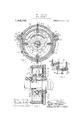
- Fig. 2 is a section taken on line Q-2 of Fig. l, with said device attached to -a wheel and axle of a vehicle, portions of said wheel and axle being broken away to save space in the drawings.
- 3 is aseotional elevation taken on line 8-3 of Fig. 1.
- 4 is an axle and 5 a wheel rotatably mounted on said axle
- 6 is a casingwhich, in the present instance, is secured to the axle 4 and is therefore prevented from rotating on said axle.
- the casing ⁇ u6 is constructed preferably in three parts, a cylindrical shaped body portion 7 and end plates 8 and 9 secured to said cy- -i lindrical body portion by bolts 10.
- the plate 8 is arranged upon'lthe inner end of said cylindrical body portion of theY casing 7 and constitutes a support for the casing 6, said plate being provided with a hub 11 which engages the axle 4, while suitable means are provided to secure said plate 8 to said rear axle to revent a relative rotary movement there etween, said means not being shown in the drawings.
- the end plate 9 is adapted to closethe outer end of said cylindrical bodyportion and is provided with an opening 12.
- the wheel 5 is arranged in close pro'xiinfl .ity to the walll 9 and has secured thereto a hubl which extends inwardly from said wheel and provides a support for the inner side of said wheel upon said axle il. ⁇
- the hub 13 has at its inner end a piston carrier 14 which is adaptedrto rotatably lit a porf tion of the' casing G, said carrier being connected to said hub by a central web 15.
- a series of'pistons 16 ⁇ are arranged in slots 17 preferably radially disposed rela;- "tively to the axis of the "pistonca'rrier 14 ⁇ and as said carrier is revolved within the casing 6 said pistons are adapted to be moved thereon during certain portions of the rotation of said carrier, by means con' sisting of segmental supports or brackets 18 andl 19 which are formed upon .the end plates 8 and 9 respectively, the outer peripheries 200i said su portsbeing arranged ily to the cylindrical portion of the casing 6.
- the supports 18 and 19 extend laterally from said platesf and 9 respectively into recesses 2l and 22 formed in opposite ends of the piston carrier 14 and these supports are each adapted to sustain a pair of rings 23 and 24 which are connected together by studs 25 upon which are mounted rollers 26.
- rollers are arranged adjacent the iuner peripheries ofy said rings and project slightly therewithin and constitute roller bearings therefor.
- the outer eripheries 27 of said rings 23 and 24 are a apted to engage the inner ends 28 of the pistons 16 during certain portions of the rotation of the piston carrier 14g and, as hereinbefore stated, force said pistons outwardly relatively to said carrier whereby the outer ends thereof project laterally beyond the periphery 29 of said carrier and cause said pistons to engage at their outer ends 30 the inner wall 31 of the casing 6, which constitutes the outer boundary of a said inner periphery or wallv 31 of the ⁇ pory tion of the casing constituting the chamber 32 make said chambervsubstantially crescent shaped and as said pistons are revolved through said chamber the peculiar shape of said chamber and the movements of said pis ⁇ tons relatively thereto 4cooperate to perform the operation of drawing fluid into said chamber through an inlet port 33 arranged adjacent to one end of said chamber and ejecting fiuid from said chamber through an outlet port 341 arranged adjacent to the op- .posite end thereof.
- theports 33 and 311 are wide o-pen and must be of a sufficient area to permit the fluid to be drawn into and ejected from said chamber 32 ⁇ without in the least retarding t-he movements of the pistons 16 and in order to provide an opening o-f the proper area
- said ports are preferably arranged longitudinally of the cylindrically shaped portion 7, while rotary valves 35 are provided to open'or close said ports, the median axial lines thereof being preferably arranged substantially parallel with the med-ian axial line of the carrier 14.
- these valves are slightly tapered to fit correspondingly tapered holes 36 in the casing 6 and are held in contact therewith by suitable means, preferably nuts 37 having screw-threaded engagement with the stem 38 thereof.
- the valves 35 are provided with slots 39 which extend transversely through said valves and are adapted to register with the ports ,33' and 34 when said valves are rotated, while levers 40 are arranged upon the ends of said valves and by which the same may be operated to open and close said ports and thereby regulate the passage of fluid therethrough.
- levers 40 are arranged upon the ends of said valves and by which the same may be operated to open and close said ports and thereby regulate the passage of fluid therethrough.
- the inner ends of saidports are arthe edges of said ranged helically relatively to the inner ,pe- I riphery thereof and thereby permit the ends 30 of said pistons to ride smoothly across the same.
- the device hereinbefore described, as stated, is constructed to be used as a brake for vehicles and the like. .It is not the intention however to limit the device to this particular application as other uses may develop to whichl said device may be applied. Furthermore certain minor details of construction may also be changed and others substituted for those herein shown without departing from the spirit of the invention.
- a device of the class described embodying, in its construction, a-.casing comprising a fluid chamber, a piston carrier, a series of pistons on said carrier adapted to draw fluid into and eject fluid from said chamber, valves adapted to control the passage of fluid into and out of said chamber and means adapted to move said pistons relatively to said carrier, said means including a segmental support and'a ring arranged on said support,
- a casing eomprisinga fluid chamber, a series of pistons adapted to revolve Within said casing,
- the inner wall of said casing constituting f said fluid chamber being eccentrically arranged relatively to the axis of rotation of said pistons, means to move said pistons into.
Landscapes
- Engineering & Computer Science (AREA)
- General Engineering & Computer Science (AREA)
- Mechanical Engineering (AREA)
- Braking Arrangements (AREA)
Description
W. P. COLLINS.
BRAKE MEGHANISM.
APPLICATION FILED MAR.31,1913.
1,084,792. 4 Patented Jan. .20, 1914.
tlhl 15ml@ TATE@ Partnr ortica.N
BRAKE MECHANISM.
Specification of Letters Patent.
Patented J 11,111.20, 1914.
Application ld March 31, 1913. Serial No. 757,852.
To all whom it may concern.'
Be it known that I, WILLIAM P. CoLLINs, a citizen of the United States, residin at Boston, in the county of Suffolk and tate of Massachusetts have invented new and useful Improvements in' Brake Mechanisms, of which the following is a specifcation.
This inventionrelates' to new and useful improvements in brake. mechanisms, particularly` though' not exclusively to brake mechanisms adapted' for use in connection with vehicles.
The object of the invention is to provide a simple, compact and durable brake having a casing provided with a fluid chamber and a series of pistons adapted to draw fluid into and eject fluid from said chamber, thel passage of saidtluid to and from said charn-i ber being regulated and controlled byvalves which upon fbeing opened or closed will eitherpermit a freerelative movement between said pistons and the casing comprising said fluid chamber or the movements of said members will be retarded. y
The object of the invention is further to provide means for moving said pistons into a positionvwithin said fluid chamber during the relative movements between said cha/mber and said pistons. v
The invention ,consists in the combina: tion and arrangement of parts whereby the above' objects and certain other objects hereinafter ap earing are attained, as set forth in the fol owing specilication and particularly pointed out in the claims,l
Beferringto the drawings:l F gure 1 is a transverse section, partly in elevation,
" through a brake mechanism embodying my invention. Fig. 2 is a section taken on line Q-2 of Fig. l, with said device attached to -a wheel and axle of a vehicle, portions of said wheel and axle being broken away to save space in the drawings. 3 is aseotional elevation taken on line 8-3 of Fig. 1.
Like numerals refer to like parts throughout the several views of the drawings.
In the drawings, 4 is an axle and 5 a wheel rotatably mounted on said axle, 6 is a casingwhich, in the present instance, is secured to the axle 4 and is therefore prevented from rotating on said axle. The casing`u6 is constructed preferably in three parts, a cylindrical shaped body portion 7 and end plates 8 and 9 secured to said cy- -i lindrical body portion by bolts 10.
.eccentrically relative The plate 8 is arranged upon'lthe inner end of said cylindrical body portion of theY casing 7 and constitutes a support for the casing 6, said plate being provided with a hub 11 which engages the axle 4, while suitable means are provided to secure said plate 8 to said rear axle to revent a relative rotary movement there etween, said means not being shown in the drawings.` The end plate 9 is adapted to closethe outer end of said cylindrical bodyportion and is provided with an opening 12.`
The wheel 5 is arranged in close pro'xiinfl .ity to the walll 9 and has secured thereto a hubl which extends inwardly from said wheel and provides a support for the inner side of said wheel upon said axle il.` The hub 13 has at its inner end a piston carrier 14 which is adaptedrto rotatably lit a porf tion of the' casing G, said carrier being connected to said hub by a central web 15.
A series of'pistons 16` are arranged in slots 17 preferably radially disposed rela;- "tively to the axis of the "pistonca'rrier 14 `and as said carrier is revolved within the casing 6 said pistons are adapted to be moved thereon during certain portions of the rotation of said carrier, by means con' sisting of segmental supports or brackets 18 andl 19 which are formed upon .the end plates 8 and 9 respectively, the outer peripheries 200i said su portsbeing arranged ily to the cylindrical portion of the casing 6.
The supports 18 and 19 extend laterally from said platesf and 9 respectively into recesses 2l and 22 formed in opposite ends of the piston carrier 14 and these supports are each adapted to sustain a pair of rings 23 and 24 which are connected together by studs 25 upon which are mounted rollers 26.
These rollers are arranged adjacent the iuner peripheries ofy said rings and project slightly therewithin and constitute roller bearings therefor.
The outer eripheries 27 of said rings 23 and 24 are a apted to engage the inner ends 28 of the pistons 16 during certain portions of the rotation of the piston carrier 14g and, as hereinbefore stated, force said pistons outwardly relatively to said carrier whereby the outer ends thereof project laterally beyond the periphery 29 of said carrier and cause said pistons to engage at their outer ends 30 the inner wall 31 of the casing 6, which constitutes the outer boundary of a said inner periphery or wallv 31 of the `pory tion of the casing constituting the chamber 32 make said chambervsubstantially crescent shaped and as said pistons are revolved through said chamber the peculiar shape of said chamber and the movements of said pis` tons relatively thereto 4cooperate to perform the operation of drawing fluid into said chamber through an inlet port 33 arranged adjacent to one end of said chamber and ejecting fiuid from said chamber through an outlet port 341 arranged adjacent to the op- .posite end thereof.
In the normal operation of the device theports 33 and 311 are wide o-pen and must be of a sufficient area to permit the fluid to be drawn into and ejected from said chamber 32 `without in the least retarding t-he movements of the pistons 16 and in order to provide an opening o-f the proper area said ports are preferably arranged longitudinally of the cylindrically shaped portion 7, while rotary valves 35 are provided to open'or close said ports, the median axial lines thereof being preferably arranged substantially parallel with the med-ian axial line of the carrier 14. Furthermore these valves are slightly tapered to fit correspondingly tapered holes 36 in the casing 6 and are held in contact therewith by suitable means, preferably nuts 37 having screw-threaded engagement with the stem 38 thereof.
The valves 35 are provided with slots 39 which extend transversely through said valves and are adapted to register with the ports ,33' and 34 when said valves are rotated, while levers 40 are arranged upon the ends of said valves and by which the same may be operated to open and close said ports and thereby regulate the passage of fluid therethrough. To prevent the pistons 16 from striking abruptly against ports during their passage through said chamber the inner ends of saidports are arthe edges of said ranged helically relatively to the inner ,pe- I riphery thereof and thereby permit the ends 30 of said pistons to ride smoothly across the same.
The device hereinbefore described, as stated, is constructed to be used as a brake for vehicles and the like. .It is not the intention however to limit the device to this particular application as other uses may develop to whichl said device may be applied. Furthermore certain minor details of construction may also be changed and others substituted for those herein shown without departing from the spirit of the invention.
Having thus described my invention, what I claim and desire by Letters Patent to secure is: l
1. A device of the class described embodying, in its construction, a-.casing comprising a fluid chamber, a piston carrier, a series of pistons on said carrier adapted to draw fluid into and eject fluid from said chamber, valves adapted to control the passage of fluid into and out of said chamber and means adapted to move said pistons relatively to said carrier, said means including a segmental support and'a ring arranged on said support,
and a series of rollerson said ring adapted to f engage said support and constituting roller bearings.
2. In a rotary brake mechanism, a casing eomprisinga fluid chamber, a series of pistons adapted to revolve Within said casing,
the inner wall of said casing constituting f said fluid chamber being eccentrically arranged relatively to the axis of rotation of said pistons, means to move said pistons into.
WILLIAM l). COLLINS.
' Witnessesz' SYDNEY E. TAF'i, MARGARETTE F, FINNERTY.
Priority Applications (1)
| Application Number | Priority Date | Filing Date | Title |
|---|---|---|---|
| US75785213A US1084792A (en) | 1913-03-31 | 1913-03-31 | Brake mechanism. |
Applications Claiming Priority (1)
| Application Number | Priority Date | Filing Date | Title |
|---|---|---|---|
| US75785213A US1084792A (en) | 1913-03-31 | 1913-03-31 | Brake mechanism. |
Publications (1)
| Publication Number | Publication Date |
|---|---|
| US1084792A true US1084792A (en) | 1914-01-20 |
Family
ID=3153019
Family Applications (1)
| Application Number | Title | Priority Date | Filing Date |
|---|---|---|---|
| US75785213A Expired - Lifetime US1084792A (en) | 1913-03-31 | 1913-03-31 | Brake mechanism. |
Country Status (1)
| Country | Link |
|---|---|
| US (1) | US1084792A (en) |
-
1913
- 1913-03-31 US US75785213A patent/US1084792A/en not_active Expired - Lifetime
Similar Documents
| Publication | Publication Date | Title |
|---|---|---|
| US1737942A (en) | Rotary fluid pump or motor | |
| US1084792A (en) | Brake mechanism. | |
| US2536938A (en) | Rotary fluid motor | |
| US1728528A (en) | Fluid-pressure rotor | |
| US1444577A (en) | Compressor | |
| US1436863A (en) | Rotary pump | |
| US1529061A (en) | Transmission mechanism for automobiles | |
| US709242A (en) | Rotary engine. | |
| US917944A (en) | Rotary engine. | |
| US904749A (en) | Rotary engine. | |
| US1086649A (en) | Brake mechanism. | |
| US992582A (en) | Rotary motor. | |
| US1614119A (en) | Brake for motor vehicles | |
| US1290657A (en) | Rotary engine. | |
| US830334A (en) | Rotary motor. | |
| US1086159A (en) | Rotary engine. | |
| US1945606A (en) | Fluid brake | |
| US806759A (en) | Fluid-power transmitter. | |
| US1012850A (en) | Rotary engine. | |
| US931785A (en) | Rotary steam-engine. | |
| US1051288A (en) | Shock-absorber. | |
| US6132196A (en) | Fluid vane motor/pump | |
| US879045A (en) | Fluid-clutch. | |
| US1565133A (en) | Rotary motor | |
| US1009405A (en) | Rotary engine. |