US10846575B1 - Probabilistic pixel biasing in low area coverage - Google Patents
Probabilistic pixel biasing in low area coverage Download PDFInfo
- Publication number
- US10846575B1 US10846575B1 US16/164,992 US201816164992A US10846575B1 US 10846575 B1 US10846575 B1 US 10846575B1 US 201816164992 A US201816164992 A US 201816164992A US 10846575 B1 US10846575 B1 US 10846575B1
- Authority
- US
- United States
- Prior art keywords
- pixel
- image data
- state
- pixels
- zero
- Prior art date
- Legal status (The legal status is an assumption and is not a legal conclusion. Google has not performed a legal analysis and makes no representation as to the accuracy of the status listed.)
- Active
Links
- 238000000034 method Methods 0.000 claims abstract description 47
- 238000002955 isolation Methods 0.000 claims description 28
- 238000010304 firing Methods 0.000 abstract 1
- 238000006243 chemical reaction Methods 0.000 description 7
- 238000010586 diagram Methods 0.000 description 3
- 230000006870 function Effects 0.000 description 2
- 230000003287 optical effect Effects 0.000 description 2
- 238000009877 rendering Methods 0.000 description 2
- 230000008901 benefit Effects 0.000 description 1
- 238000005516 engineering process Methods 0.000 description 1
- 238000010348 incorporation Methods 0.000 description 1
- 238000013507 mapping Methods 0.000 description 1
- 238000012986 modification Methods 0.000 description 1
- 230000004048 modification Effects 0.000 description 1
- 230000008569 process Effects 0.000 description 1
- 230000007704 transition Effects 0.000 description 1
Images


Classifications
-
- G—PHYSICS
- G06—COMPUTING; CALCULATING OR COUNTING
- G06K—GRAPHICAL DATA READING; PRESENTATION OF DATA; RECORD CARRIERS; HANDLING RECORD CARRIERS
- G06K15/00—Arrangements for producing a permanent visual presentation of the output data, e.g. computer output printers
- G06K15/02—Arrangements for producing a permanent visual presentation of the output data, e.g. computer output printers using printers
- G06K15/18—Conditioning data for presenting it to the physical printing elements
- G06K15/1835—Transforming generic data
- G06K15/1842—Geometric transformations, e.g. on raster data
- G06K15/1843—Changing size or raster resolution
-
- B—PERFORMING OPERATIONS; TRANSPORTING
- B41—PRINTING; LINING MACHINES; TYPEWRITERS; STAMPS
- B41J—TYPEWRITERS; SELECTIVE PRINTING MECHANISMS, i.e. MECHANISMS PRINTING OTHERWISE THAN FROM A FORME; CORRECTION OF TYPOGRAPHICAL ERRORS
- B41J2/00—Typewriters or selective printing mechanisms characterised by the printing or marking process for which they are designed
- B41J2/005—Typewriters or selective printing mechanisms characterised by the printing or marking process for which they are designed characterised by bringing liquid or particles selectively into contact with a printing material
- B41J2/01—Ink jet
- B41J2/015—Ink jet characterised by the jet generation process
- B41J2/04—Ink jet characterised by the jet generation process generating single droplets or particles on demand
- B41J2/045—Ink jet characterised by the jet generation process generating single droplets or particles on demand by pressure, e.g. electromechanical transducers
- B41J2/04501—Control methods or devices therefor, e.g. driver circuits, control circuits
- B41J2/0456—Control methods or devices therefor, e.g. driver circuits, control circuits detecting drop size, volume or weight
-
- B—PERFORMING OPERATIONS; TRANSPORTING
- B41—PRINTING; LINING MACHINES; TYPEWRITERS; STAMPS
- B41J—TYPEWRITERS; SELECTIVE PRINTING MECHANISMS, i.e. MECHANISMS PRINTING OTHERWISE THAN FROM A FORME; CORRECTION OF TYPOGRAPHICAL ERRORS
- B41J2/00—Typewriters or selective printing mechanisms characterised by the printing or marking process for which they are designed
- B41J2/005—Typewriters or selective printing mechanisms characterised by the printing or marking process for which they are designed characterised by bringing liquid or particles selectively into contact with a printing material
- B41J2/01—Ink jet
- B41J2/015—Ink jet characterised by the jet generation process
- B41J2/04—Ink jet characterised by the jet generation process generating single droplets or particles on demand
- B41J2/045—Ink jet characterised by the jet generation process generating single droplets or particles on demand by pressure, e.g. electromechanical transducers
- B41J2/04501—Control methods or devices therefor, e.g. driver circuits, control circuits
- B41J2/04586—Control methods or devices therefor, e.g. driver circuits, control circuits controlling heads of a type not covered by groups B41J2/04575 - B41J2/04585, or of an undefined type
-
- B—PERFORMING OPERATIONS; TRANSPORTING
- B41—PRINTING; LINING MACHINES; TYPEWRITERS; STAMPS
- B41J—TYPEWRITERS; SELECTIVE PRINTING MECHANISMS, i.e. MECHANISMS PRINTING OTHERWISE THAN FROM A FORME; CORRECTION OF TYPOGRAPHICAL ERRORS
- B41J2/00—Typewriters or selective printing mechanisms characterised by the printing or marking process for which they are designed
- B41J2/005—Typewriters or selective printing mechanisms characterised by the printing or marking process for which they are designed characterised by bringing liquid or particles selectively into contact with a printing material
- B41J2/01—Ink jet
- B41J2/21—Ink jet for multi-colour printing
- B41J2/2121—Ink jet for multi-colour printing characterised by dot size, e.g. combinations of printed dots of different diameter
-
- G—PHYSICS
- G06—COMPUTING; CALCULATING OR COUNTING
- G06K—GRAPHICAL DATA READING; PRESENTATION OF DATA; RECORD CARRIERS; HANDLING RECORD CARRIERS
- G06K15/00—Arrangements for producing a permanent visual presentation of the output data, e.g. computer output printers
- G06K15/02—Arrangements for producing a permanent visual presentation of the output data, e.g. computer output printers using printers
- G06K15/10—Arrangements for producing a permanent visual presentation of the output data, e.g. computer output printers using printers by matrix printers
- G06K15/102—Arrangements for producing a permanent visual presentation of the output data, e.g. computer output printers using printers by matrix printers using ink jet print heads
- G06K15/105—Multipass or interlaced printing
- G06K15/107—Mask selection
Definitions
- Systems and methods herein generally relate to printing devices, and more particularly to upscaling an image associated with a multi-state printhead(s) to an image associated with a single-state printhead(s).
- Ink-jet printers fire drops of ink from one or more printheads onto a print medium or image-receiving surface.
- multi-state ink-jet printers have been developed with inkjets that can eject drops of ink with different sizes (i.e. volumes of ink), thereby improving image quality.
- efficient methods of accurately altering image resolution and enhancement are required to take advantage of the technology.
- conventional upscaling techniques can create certain undesirable artefacts and graininess in the upscaled output image.
- particular upscaling methods and devices generate a graininess in low-coverage areas of an image, but not in areas of more coverage.
- a method of upscaling an input image from a lower resolution to a higher resolution comprising: receiving a multi-state contone image data associated with the input image having a first resolution, wherein the multi-state contone image data includes a plurality of pixel values and an associated ink droplet size selected from two or more possible ink droplet sizes for each pixel of the multi-state contone image data; converting each pixel of the multi-state contone image data into a pattern of single-state inkjets activated in a plurality of N-by-M blocks of a binary output image data, wherein the single-state print jets are configured to eject ink droplets of a single size; and outputting the binary output image data having a second resolution, wherein the binary output image data.
- N and M are integers greater than or equal to 1, and the second resolution is greater than the first resolution.
- the pattern of single-state inkjets activated within one or more of the N-by-M blocks is randomized.
- the method also includes operating at least one single-state inkjet in a single-state printhead with reference to the binary output image data to form an output image on a print medium or image-receiving surface that corresponds to the binary output image data.
- a method of upscaling an input image from a lower resolution to a higher resolution comprising: receiving a multi-state contone image data associated with the input image having a first resolution, wherein the multi-state contone image data includes a plurality of pixel values and an associated ink droplet size selected from two or more possible ink droplet sizes for each pixel of the multi-state contone image; determining a degree of isolation for each of the pixels of the multi-state contone image data; assigning a bias probability value to each pixel of the multi-state contone image data based on the degree of isolation corresponding to each pixel; converting each pixel of the multi-state contone image data into a pattern of single-state inkjets activated in a plurality of N-by-M blocks of a binary output image data based on the bias probability value assigned to each pixel, wherein the single-state inkjets are configured to eject ink droplets of a single size; and outputting the binary
- the degree of isolation for a pixel of the multi-state contone image data is determined by: receiving pixel values for a plurality of pixels within P-by-Q block of the multi-state contone image data; and determining a number of zero-pairs associated with a first pixel of the plurality of pixels within the P-by-Q block; wherein P and Q can be integers greater than or equal to 2, and the degree of isolation of the first pixel corresponds to the number of zero-pairs associated with the first pixel.
- a printing system that upscales an input image from a lower resolution to a higher resolution
- the system comprising: a multi-state contone image data associated with the input image having a first resolution, wherein the multi-state contone image data includes a plurality of pixel values and an associated ink droplet size selected from two or more possible ink droplet sizes for each pixel of the multi-state contone image; one or more printheads configured to operate one or more single-state inkjets to eject ink droplets of only one size to form pixels in ink images on a print medium or image receiving surface; a processor operatively connected to the one or more printheads; and a memory connected to the processor and containing programming instructions that are configured to instruct the processor to (i) receive from an image source the multi-state contone image data, (ii) convert each pixel of the multi-state contone image data into a pattern of single-state inkjets activated in a plurality of N-by-M
- N and M can be integers greater than or equal to 1, and the second resolution is greater than the first resolution.
- the memory of the printing system contains programming instructions configured to instruct the processor to operate at least one inkjet in the one or more printheads with reference to the binary output image data to form an output image on a print medium or image-receiving surface that corresponds to the binary output image data
- one or more of the pixels of the multi-state contone image data are converted into a pattern of activated inkjets within the N-by-M blocks, wherein the pattern is a randomized pattern.
- the memory of the printing system contains programming instructions configured to instruct the processor to: determine a number of zero-pairs associated with one or more pixels of the multi-state contone image data by analyzing a plurality of pixels surrounding the one or more pixels; assign a bias probability value to each of the one or more pixels based on the number of zero-pairs associated with each of the one or more pixels; determine whether to bias each of the one or more pixels based on the bias probability value assigned to each of the one or more pixels; and convert each of the one or more pixels of the multi-state contone image data into a pattern of activated inkjets in one or more N-by-M blocks of the binary output image data, wherein N and M are integers greater than or equal to 2, and wherein the pattern of activated inkjets corresponding to each of the one or more pixels is one of a biased pattern or a randomized pattern based on the determination of whether to bias each of the one or more pixels.
- a pixel of the multi-state contone image data can have from between zero and four zero-pairs, including zero zero-pairs, one zero-pair, two zero-pairs, three zero-pairs, and four-zero pairs.
- FIG. 1 is a flowchart of a method for upscaling an input image from a lower resolution to a higher resolution according to an exemplary embodiment of this disclosure.
- FIG. 2 is a second flowchart illustrating in further detail one aspect of the method of upscaling an input image according to an exemplary embodiment of this disclosure.
- FIGS. 3A-3I are illustrations of various P-by-Q blocks of a multi-state contone image data with pixels having various degrees of isolation.
- FIGS. 4A and 4B are illustrations of addition P-by-Q blocks of a multi-state contone image data with pixels selected along a corner ( 4 A) and edge ( 4 B) of an input image.
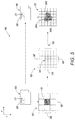
- FIG. 5 is a schematic illustrating an upscaling method according to an exemplary embodiment of this disclosure.
- FIG. 6 is a block diagram of a printing system for performing the methods disclosed herein according to an exemplary embodiment of this disclosure.
- FIG. 7 is a second block diagram of a printing system for performing the methods disclosed herein according to another exemplary embodiment of this disclosure.
- tone image data refers to multi-bit digital data representing an image comprising continuous tone data values used to identify an intensity level for a primary color (e.g. cyan, magenta, yellow, and black) at each pixel of the image, which can be used in the ink of a printer to reproduce the image.
- a primary color e.g. cyan, magenta, yellow, and black
- multi-state contone image data refers to contone image data that includes a parameter corresponding to the size (i.e. volume) of the ink droplets to be ejected by a multi-state inkjet.
- a “multi-state inkjet” or a “multi-state printhead” similarly refer to an inkjet and a printhead configured to eject multiple ink droplet sizes, for example, based on a multi-state contone image data.
- low-coverage area refers to regions of an image wherein marked pixels are relatively isolated. That is, for example, when an image is formed, ink droplets are relatively spaced out (i.e. a minimal number of inkjets are operated and amount ink used within a certain region). These low-coverage areas may represent, for example, light or highlighted areas within an image. Conversely, the terms “mid-coverage areas” and “high-coverage areas” refer to regions wherein pixels are less isolated, more inkjets are operated, and/or more ink is used.
- FIG. 1 a basic method 100 for upscaling an input image from a lower resolution to a higher resolution is depicted in FIG. 1 .
- the method 100 begins at S 100 .
- a multi-state contone image data representing an input image is received.
- the multi-state contone image data includes a plurality of pixel values (i.e. continuous tone data values) for each pixel, as well as a parameter associating an ink droplet size to be used if printed using one or more multi-state inkjets.
- the associated ink droplet size can be selected from two or more possible ink droplet sizes, or from three or more possible ink droplet sizes.
- the associated ink droplet size can be selected from a first volume, a second volume, and a third volume.
- the two or more different possible ink droplet sizes may range from about 3 to about 15 picoliters.
- the first volume may be 4 picoliters
- the second volume may be 8 picoliters
- the third volume may be 12 picoliters.
- each pixel of the multi-state contone image data is converted (i.e. mapped) into a pattern of inkjets activated in a plurality of N-by-M blocks of a binary output image data.
- the variables “N” and “M” can be integers greater than or equal to 1, including greater than or equal to 2.
- each N-by-M block corresponds to the upscaled single pixel of the input image represented by the multi-state contone image data. That is, for example, an input image with a resolution of 600 dots per inch (dpi) may be upscaled to an output image with a resolution of 1200 dpi by mapping each pixel of the input image data to a plurality of 2-by-2 blocks of the output image.
- dpi dots per inch
- the continuous tone values (i.e. pixel values) corresponding to each of the pixels of the multi-state contone image data are converted (i.e. mapped) to a pattern of inkjets activated in a plurality of 2-by-2 blocks of the output image data.
- the output image data stores the patterns of activated inkjets for each of the N-by-M blocks of the output image as a binary output image data.
- an associated “1” or “0” value is designated, based on the patterns of activated inkjets generated.
- the patterns of activated inkjets forming the binary output image data also comprise an associated position parameter for each pixel of the output image (i.e. a parameter identifying where an ink drop should be placed in relation to each pixel).
- one or more ink droplets may be randomly placed, or may be biased in a particular direction (e.g. upper left, upper right, lower left, lower right, etc.) and by varying degrees.
- the binary output image data is output.
- the binary output image data may be output to an inkjet printer to be printed on a print medium, or may be output to an electronic memory device.
- At a step S 140 at least one inkjet may be operated with reference to the binary output image data to form an output image that corresponds to the binary output image data.
- the inkjets may be operated such that the output image is formed using ink droplets of only one size.
- the inkjets are single-state inkjets (i.e. eject only one drop size in order to form an image on a print medium or image-receiving surface).
- the multi-state contone image data corresponding to an input image may have a first resolution
- the output image data may have a second resolution, wherein the second resolution is greater than the first resolution.
- the second resolution is at least twice the first resolution.
- the first resolution may be from about 300 to about 600 spots per inch (“spi”)
- the second resolution may be from about 600 to about 2400 spi.
- other resolutions are contemplated, including resolutions greater 2400 spi and resolutions less than 300 spi.
- step S 150 the method ends.
- step S 110 wherein the multi-state contone image data associated with an input image having a first resolution is received, a degree of isolation for each of the pixels of the multi-state contone image data is determined. In low-coverage areas, the degree of isolation of one or more pixels in a region will be higher.
- the degree of isolation of a first pixel of the multi-state contone image may be determined by a first step S 112 , wherein pixel values for a plurality of pixels within a P-by-Q block of the multi-state contone image data is selected and received.
- the P-by-Q block may define a subset of pixels of the multi-state contone image, and includes the first pixel for which a degree of isolation is being determined.
- P and “Q” can be integers greater than or equal to 2. In further embodiments, “P” and “Q” may independently be 2 or 3.
- a number of zero-pairs for the first pixel is determined.
- zero-pairs refers to the pairs of pixels on opposing sides of the first pixel, wherein both pixels in the pair of pixels have a pixel value of zero (i.e. is empty and an inkjet would not eject an ink droplet in that position).
- a pixel may have 0, 1, 2, 3, or 4 zero-pairs.
- FIGS. 3A-3I several P-by-Q blocks 301 , 302 , 303 , 304 , 305 , 306 , 307 , 308 , 309 of pixels are depicted to illustrate various combinations of zero-pairs wherein P and Q are both 3 .
- each P-by-Q block 301 , 302 , 303 , 304 , 305 , 306 , 307 , 308 , 309 of pixels is illustrated on an X-Y coordinate system, with a first pixel 300 A, 300 B, 300 C, 300 D, 300 E, 300 F, 300 G, 300 H, 300 I located at position (0,0). Also for simplicity, pixels having a non-zero value are depicted as shaded, whereas pixels having a zero value are not shaded. However, those of skill in the art will understand that a variety of pixel values may comprise a plurality of non-zero values.
- first pixel 300 A located at (0,0) within the P-by-Q block 301 has four zero-pairs: a first pair located at ( ⁇ 1,0) and (+1,0); a second pair located at (0, ⁇ 1) and (0,+1); a third pair located at ( ⁇ 1, ⁇ 1) and (+1, ⁇ 1); and a fourth pair located at ( ⁇ 1,+1) and (+1, ⁇ 1).
- first pixel 300 B located at (0,0) within the P-by-Q block 302 has three zero-pairs: a first pair located at ( ⁇ 1,0) and (+1,0); a second pair located at (0, ⁇ 1) and (0,+1); and a third pair located at ( ⁇ 1, ⁇ 1) and (+1,+1).
- the pixel located at (+1, ⁇ 1) has a non-zero value
- the pair including (+1, ⁇ 1) and ( ⁇ 1,+1) is not a zero-pair.
- the pixel located at ( ⁇ 1,+1) also has a non-zero pair, thus the pair including (+1, ⁇ 1) and ( ⁇ 1,+1) is not a zero-pair.
- the first pixels 300 B and 300 C have only three zero-pairs.
- the pixel values are identify and the number of non-zero pairs are counted.
- the degree of isolation associated with a pixel of the multi-state contone image is equal to the number of zero-pairs determined for that pixel.
- a degree of isolation of zero for a pixel indicates that the pixel has zero zero-pairs and is not isolated.
- a degree of isolation of four for a pixel indicates that the pixel has four zero-pairs is completely isolated.
- P-by-Q blocks 305 , 306 , and 308 each have four pixels with a pixel value of zero, the corresponding first pixels 300 E, 300 F, and 300 H each have a different degree of isolation.
- FIGS. 4A and 4B the zero-pairs determination for a pixel on the border of the image is illustrated.
- a pixel 401 A occupying a corner of the image is selected within the P-by-Q block 400 A, which is located at (0,0), is surrounded by pixels located (+1,0), (+1,+1), and (0,+1). Because the no pixels exist off-image, that is, along row 405 A and column 410 A, hypothetical pixels, such as pixel 415 A located at (+1, ⁇ 1), is defaulted to a value of zero.
- FIG. 4A a pixel 401 A occupying a corner of the image is selected within the P-by-Q block 400 A, which is located at (0,0), is surrounded by pixels located (+1,0), (+1,+1), and (0,+1). Because the no pixels exist off-image, that is, along row 405 A and column 410 A, hypothetical pixels, such as pixel 415 A located at (+1, ⁇ 1), is defaulted to a value
- a pixel 401 B occupies a position along the edge of an image, and no pixels exist off-image along row 405 B.
- the hypothetical pixels 415 B along row 405 B are defaulted to a value of zero. For example, in FIGS. 4A and 4B , pixels 401 A and 401 B would have four zero-pairs each.
- bias probability value refers to a value representing the probability that the ink droplets within a pattern of inkjets generated are biased in a particular direction.
- the pattern of inkjets activated corresponding a pixel of a lower resolution image may be randomized when upscaling that pixel, however, this has been found to introduce a graininess in low-coverage areas (i.e. areas where there is a high concentration of isolated pixels).
- the graininess may be reduced or eliminated.
- a bias probability value based on the degree of isolation of a pixel (i.e. number of zero-pairs)
- a smooth transition from low-coverage areas to higher-coverage areas can be obtained.
- the bias probability value associated with a pixel may be between 0 and 1.
- the bias probability value may be 0, 0.25, 0.5, 0.75, or 1.
- a pixel of the multi-state contone image having a high degree of isolation will have a high bias probability value, while a pixel having a low degree of isolation will have a low bias probability value.
- a pixel having four zero-pairs has a bias probability value of 1, a pixel having three zero-pairs has a bias probability value of 0.75, a pixel having two zero-pairs has a bias probability value of 0.5, a pixel having one zero-pair has a bias probability value of 0.25, and a pixel having no zero-pairs has a bias probability value of 0.
- other probability values are contemplated.
- the bias probability value is used in determining whether to bias the pixel of the multi-state contone image data when converting the pixel into a pattern of inkjets to be activated in the higher resolution binary image data.
- the particular pattern of inkjets that will be used is determined or configured prior to printing. For example, if a pixel has a bias probability of 0.25, then there is a 25% chance that the pixel will be rendered using the particular pre-determined pattern of inkjets, and a 75% chance that the pixel will be rendered using a randomized or other standard rendering technique.
- a random number generator may be used to determine whether to bias the pixel based on the bias probability value associated with that pixel.
- the pixel is converted into a randomized pattern of activated inkjets in a N-by-M block of the output image data at a step S 120 A.
- the position of the ink droplets to be ejected from the inkjets within a N-by-M block corresponding to the pixel and forming a portion of the upscaled output image may be randomly placed within that N-by-M block.
- the pixel is converted into a particular pattern of activated inkjets, determined a-priori, within a N-by-M block of the output image data at a step S 120 B.
- position of the ink droplets to be ejected from the inkjets within a N-by-M block corresponding to the pixel and forming a portion of the upscaled output image may be selectively placed within that N-by-M block to be biased in a particular direction.
- steps S 112 through S 120 A/S 120 B are repeated for one or more pixels of the multi-state contone image.
- steps S 112 through S 120 A/ 120 B are repeated for a plurality of pixels, including for each pixel of the multi-state contone image.
- the steps S 112 through 120 A/ 120 B may be repeated only for each pixel having a non-zero value.
- FIG. 5 depicts the conversion 500 of a pixel 501 within a P-by-Q block 502 of a multi-state contone image data representing a low resolution input image 503 into a pattern of inkjets to be activated to eject ink droplets 504 A, 504 B, 504 C of a consistent volume within a N-by-M block 505 of an upscaled output image 506 generated by operating at least one inkjet with reference to the binary output image data.
- “P” 507 and “Q” 508 are both three
- “N” 509 and “M” 510 are both two.
- the pattern of inkjets activated within the N-by-M block 505 may be a randomized pattern of ink droplets 504 A, 504 B, 504 C, or may be a biased pattern of ink 504 A, 504 B, 504 C. This process may then be repeated for additional P-by-Q blocks 511 of the multi-state contone image data, including a plurality of P-by-Q blocks.
- the pattern of activated inkjets includes the number of droplets 504 A, 504 B, 504 C ejected. For example, in some embodiments, no ink droplets may be fired within the N-by-M block 505 , or only one ink droplet may be fired, or two ink droplets may be fired, or three ink droplets may be fired.
- the pattern of inkjets activated within at least one N-by-M block 505 of the binary output image data includes ejecting at least one ink droplet. In other embodiments, the pattern includes ejecting at least two ink droplets, and in still other embodiments, the pattern includes ejecting at least three ink droplets.
- FIG. 6 illustrates a block diagram of a printing system 600 for upscaling and converting a multi-state contone image data associated with an input image into a higher resolution, binary output image data.
- the printing system 600 can be used with systems and methods disclosed herein and can include, for example, a printer, copier, multi-function machine, multi-function device (MFD), etc.
- the system 600 includes a tangible processor 602 , a memory 604 , one or more input/output (I/O) interfaces 606 , 608 , and a controller/bus 610 that operatively connects the processor 602 , memory 604 , and I/O interfaces 606 , 608 together.
- the memory 604 can include instructions 612 for performing one or more of the steps of the methods described herein, and the processor 602 may execute such instructions 612 for performing at least a part or all of the steps of the methods discussed above.
- the memory 604 may represent any type of non-transitory computer readable medium such as random access memory (RAM), read only memory (ROM), magnetic disk or tape, optical disk, flash memory, or holographic memory.
- the memory 306 comprises a combination of random access memory and read only memory.
- the processor 304 and memory 306 may be combined in a single chip.
- the I/O interfaces 606 , 608 may allow the system 600 to communicate with other devices via a wired and/or wireless connection, or via a computer network.
- the processor 602 can be variously embodied, such as by a single-core processor, a dual-core processor (or more generally by a multiple-core processor), a digital processor, and cooperating method coprocessor, a digital controller, or the like.
- the term “software,” as used herein, is intended to encompass any collection or set of instructions executable by a computer or other digital system so as to configure the computer or other digital system to perform the task that is the intent of the software.
- the term “software” is also intended to encompass such instructions stored in storage mediums such as RAM, a hard disk, optical disk, or so forth, and is also intended to encompass so-called “firmware” that is software stored on a ROM or so forth.
- Such software may be organized in various ways, and may include software components organized as libraries, Internet-based programs stored on a remote server or so forth, source code, interpretive code, object code, directly executable code, and so forth. It is contemplated that the software may invoke system-level code or calls to other software residing on a server or other location to perform certain functions.
- the printing system 600 can include memory 604 storing instructions 612 including an input component 614 , an isolation component 616 , a bias probability component 618 , a random conversion component 620 , a biased conversion component 622 , and an output component 622 .
- the memory 604 may also store specific data structures, such as input image data 630 , output image data 632 , degrees of isolation data 634 , bias probability tables 636 , bias probability value data 638 , and the like.
- the input component 614 may be configured to receive, from an image source 626 , image data 628 such as a multi-state contone image data 630 , associated with an input image 648 ( FIG. 7 ). In other embodiments, the input component 614 may be configured to convert the image data 624 into a multi-state contone image data 628 .
- the memory 604 includes instructions configured to convert each pixel of the multi-state contone image data into a pattern of activated inkjets in a plurality of N-by-M blocks of a binary output image data 630 .
- this is accomplished by an isolation component 616 configured to determine a degree of isolation 634 of one or more pixels of the multi-state contone image data 630 .
- the degree of isolation associated with the one or more pixels may be calculated by determining the number of zero-pairs associated with a pixel of the one or more pixels.
- a probability component 618 may assign a bias probability value 638 to each of the one or more pixels based on the corresponding degree of isolation (i.e.
- the bias probability component 618 may also determine whether to bias one or more of the pixels based on the bias probability value 638 associated with each pixel. Then, either the random conversion component 620 or the biased conversion component 622 is used to convert the multi-state contone image data 630 into a higher resolution binary output image data 632 .
- the random conversion component 620 can be configured to generate a randomized pattern of activated inkjets within one or more of the N-by-M blocks of the binary output image data 632
- the biased conversion component 622 can be configured to generate a biased pattern of activated inkjets within one or more of the N-by-M blocks of the binary output image data 632 .
- the memory 612 may also contain an output component 624 configured instruct the processor to output the higher resolution binary output image data 632 .
- the output image data 632 may be output to another printer inside or outside of the system 600 , or to another memory device for storage.
- the output component 624 may be configured to operate at least one inkjet with reference to the binary output image data 632 to form an output image 644 on a print medium 646 (i.e. image-receiving surface) that corresponds to the binary output image data 632 .
- the system 600 may also include additional components 640 , including one or more printheads 642 comprising at least one inkjet, which may be operated by the processor 602 based on instructions 612 stored in the memory 604 .
Abstract
Description
Claims (16)
Priority Applications (1)
| Application Number | Priority Date | Filing Date | Title |
|---|---|---|---|
| US16/164,992 US10846575B1 (en) | 2018-10-19 | 2018-10-19 | Probabilistic pixel biasing in low area coverage |
Applications Claiming Priority (1)
| Application Number | Priority Date | Filing Date | Title |
|---|---|---|---|
| US16/164,992 US10846575B1 (en) | 2018-10-19 | 2018-10-19 | Probabilistic pixel biasing in low area coverage |
Publications (2)
| Publication Number | Publication Date |
|---|---|
| US20200349404A1 US20200349404A1 (en) | 2020-11-05 |
| US10846575B1 true US10846575B1 (en) | 2020-11-24 |
Family
ID=73017755
Family Applications (1)
| Application Number | Title | Priority Date | Filing Date |
|---|---|---|---|
| US16/164,992 Active US10846575B1 (en) | 2018-10-19 | 2018-10-19 | Probabilistic pixel biasing in low area coverage |
Country Status (1)
| Country | Link |
|---|---|
| US (1) | US10846575B1 (en) |
Citations (4)
| Publication number | Priority date | Publication date | Assignee | Title |
|---|---|---|---|---|
| US5696845A (en) | 1993-12-17 | 1997-12-09 | Xerox Corporation | Method for design and implementation of an image resolution enhancement system that employs statistically generated look-up tables |
| US6771392B1 (en) | 1999-09-24 | 2004-08-03 | Xerox Corporation | High resolution image mapping for simulating high resolution printing using high addressability without affecting halftone rendering |
| US20070291065A1 (en) * | 2006-06-19 | 2007-12-20 | Canon Kabushiki Kaisha | Inkjet printing apparatus, printing control method for inkjet printing apparatus, program, and storage medium |
| US7440139B2 (en) | 2005-01-13 | 2008-10-21 | Xerox Corporation | Systems and methods for controlling a tone reproduction curve using error diffusion |
-
2018
- 2018-10-19 US US16/164,992 patent/US10846575B1/en active Active
Patent Citations (4)
| Publication number | Priority date | Publication date | Assignee | Title |
|---|---|---|---|---|
| US5696845A (en) | 1993-12-17 | 1997-12-09 | Xerox Corporation | Method for design and implementation of an image resolution enhancement system that employs statistically generated look-up tables |
| US6771392B1 (en) | 1999-09-24 | 2004-08-03 | Xerox Corporation | High resolution image mapping for simulating high resolution printing using high addressability without affecting halftone rendering |
| US7440139B2 (en) | 2005-01-13 | 2008-10-21 | Xerox Corporation | Systems and methods for controlling a tone reproduction curve using error diffusion |
| US20070291065A1 (en) * | 2006-06-19 | 2007-12-20 | Canon Kabushiki Kaisha | Inkjet printing apparatus, printing control method for inkjet printing apparatus, program, and storage medium |
Also Published As
| Publication number | Publication date |
|---|---|
| US20200349404A1 (en) | 2020-11-05 |
Similar Documents
| Publication | Publication Date | Title |
|---|---|---|
| US8451493B2 (en) | Processor, method and program for processing data using a mask pattern with print permission parts arranged at a distance of corresponding integral multiple areas | |
| JP4519876B2 (en) | Data processing apparatus, data processing method and program | |
| EP2107508A2 (en) | Image processing apparatus and image processing method | |
| JP2006005899A (en) | Image outputting system for outputting image while encoding it by a plurality of pixels | |
| JP4241823B2 (en) | Dot data processing apparatus, image output system and methods thereof | |
| US8382228B2 (en) | Image forming apparatus and image forming method | |
| JP4564979B2 (en) | Data processing apparatus, recording apparatus, and mask pattern manufacturing method | |
| JP5183688B2 (en) | Data processing apparatus and data generation method | |
| JP5268875B2 (en) | Image forming apparatus and image forming method | |
| EP0944024B1 (en) | Reduction of periodic artifacts in incremental printing | |
| US10846575B1 (en) | Probabilistic pixel biasing in low area coverage | |
| JP2006231902A (en) | Printer, program and method for controlling the printer apparatus, program and method for generating printing data | |
| US9135536B2 (en) | Image processing apparatus and image processing method generating binary data specifying dot arrangement in a unit area of a print medium | |
| JP6896405B2 (en) | Recording device and recording method | |
| JP2007245583A (en) | Inkjet recorder, inkjet recording method and program | |
| JP4597159B2 (en) | Data processing apparatus, mask pattern manufacturing method, and data processing method | |
| JP3840240B2 (en) | Inkjet recording method, inkjet recording apparatus, and inkjet recording system | |
| US8988734B2 (en) | Image processing apparatus and control method configured to complement a recording amount assigned to defective nozzles | |
| JP2006229810A (en) | Image output system for outputting image, while coding a plurality of pixels each | |
| JP2011131575A (en) | Data generation method, data generation apparatus, and recording device | |
| JP5899564B2 (en) | Inkjet printing method | |
| JP2006224616A (en) | Recording method and recording system | |
| JP2006212907A (en) | Printing apparatus, printing program, printing method and image processing apparatus, image processing program, image processing method, and recording medium recorded with the same | |
| JP2005059364A (en) | Inkjet recording method, inkjet recorder, and inkjet recording system | |
| US11683437B1 (en) | Print fluid drop dispensation mask with entry moved to entry for adjacent pass to avoid repeated dispensation for a pixel per pass |
Legal Events
| Date | Code | Title | Description |
|---|---|---|---|
| AS | Assignment |
Owner name: XEROX CORPORATION, CONNECTICUT Free format text: ASSIGNMENT OF ASSIGNORS INTEREST;ASSIGNORS:SCHWEID, STUART;TRIPLETT, ROGER L.;NEWELL, JOHN;REEL/FRAME:047233/0014 Effective date: 20181017 |
|
| FEPP | Fee payment procedure |
Free format text: ENTITY STATUS SET TO UNDISCOUNTED (ORIGINAL EVENT CODE: BIG.); ENTITY STATUS OF PATENT OWNER: LARGE ENTITY |
|
| STCF | Information on status: patent grant |
Free format text: PATENTED CASE |
|
| AS | Assignment |
Owner name: CITIBANK, N.A., AS AGENT, DELAWARE Free format text: SECURITY INTEREST;ASSIGNOR:XEROX CORPORATION;REEL/FRAME:062740/0214 Effective date: 20221107 |
|
| AS | Assignment |
Owner name: XEROX CORPORATION, CONNECTICUT Free format text: RELEASE OF SECURITY INTEREST IN PATENTS AT R/F 062740/0214;ASSIGNOR:CITIBANK, N.A., AS AGENT;REEL/FRAME:063694/0122 Effective date: 20230517 |
|
| AS | Assignment |
Owner name: CITIBANK, N.A., AS COLLATERAL AGENT, NEW YORK Free format text: SECURITY INTEREST;ASSIGNOR:XEROX CORPORATION;REEL/FRAME:064760/0389 Effective date: 20230621 |
|
| AS | Assignment |
Owner name: JEFFERIES FINANCE LLC, AS COLLATERAL AGENT, NEW YORK Free format text: SECURITY INTEREST;ASSIGNOR:XEROX CORPORATION;REEL/FRAME:065628/0019 Effective date: 20231117 |
|
| AS | Assignment |
Owner name: CITIBANK, N.A., AS COLLATERAL AGENT, NEW YORK Free format text: SECURITY INTEREST;ASSIGNOR:XEROX CORPORATION;REEL/FRAME:066741/0001 Effective date: 20240206 |