US1084635A - Rotary engine. - Google Patents
Rotary engine. Download PDFInfo
- Publication number
- US1084635A US1084635A US63232511A US1911632325A US1084635A US 1084635 A US1084635 A US 1084635A US 63232511 A US63232511 A US 63232511A US 1911632325 A US1911632325 A US 1911632325A US 1084635 A US1084635 A US 1084635A
- Authority
- US
- United States
- Prior art keywords
- piston
- hub
- rotary engine
- engine
- guide
- Prior art date
- Legal status (The legal status is an assumption and is not a legal conclusion. Google has not performed a legal analysis and makes no representation as to the accuracy of the status listed.)
- Expired - Lifetime
Links
- 238000012856 packing Methods 0.000 description 5
- 238000010408 sweeping Methods 0.000 description 2
- 230000003534 oscillatory effect Effects 0.000 description 1
- XLYOFNOQVPJJNP-UHFFFAOYSA-N water Substances O XLYOFNOQVPJJNP-UHFFFAOYSA-N 0.000 description 1
Images


Classifications
-
- F—MECHANICAL ENGINEERING; LIGHTING; HEATING; WEAPONS; BLASTING
- F04—POSITIVE - DISPLACEMENT MACHINES FOR LIQUIDS; PUMPS FOR LIQUIDS OR ELASTIC FLUIDS
- F04C—ROTARY-PISTON, OR OSCILLATING-PISTON, POSITIVE-DISPLACEMENT MACHINES FOR LIQUIDS; ROTARY-PISTON, OR OSCILLATING-PISTON, POSITIVE-DISPLACEMENT PUMPS
- F04C18/00—Rotary-piston pumps specially adapted for elastic fluids
- F04C18/30—Rotary-piston pumps specially adapted for elastic fluids having the characteristics covered by two or more of groups F04C18/02, F04C18/08, F04C18/22, F04C18/24, F04C18/48, or having the characteristics covered by one of these groups together with some other type of movement between co-operating members
- F04C18/34—Rotary-piston pumps specially adapted for elastic fluids having the characteristics covered by two or more of groups F04C18/02, F04C18/08, F04C18/22, F04C18/24, F04C18/48, or having the characteristics covered by one of these groups together with some other type of movement between co-operating members having the movement defined in group F04C18/08 or F04C18/22 and relative reciprocation between the co-operating members
- F04C18/344—Rotary-piston pumps specially adapted for elastic fluids having the characteristics covered by two or more of groups F04C18/02, F04C18/08, F04C18/22, F04C18/24, F04C18/48, or having the characteristics covered by one of these groups together with some other type of movement between co-operating members having the movement defined in group F04C18/08 or F04C18/22 and relative reciprocation between the co-operating members with vanes reciprocating with respect to the inner member
- F04C18/352—Rotary-piston pumps specially adapted for elastic fluids having the characteristics covered by two or more of groups F04C18/02, F04C18/08, F04C18/22, F04C18/24, F04C18/48, or having the characteristics covered by one of these groups together with some other type of movement between co-operating members having the movement defined in group F04C18/08 or F04C18/22 and relative reciprocation between the co-operating members with vanes reciprocating with respect to the inner member the vanes being pivoted on the axis of the outer member
Definitions
- mitnrnsm v (if; @a/z/w/ my? llnumtnr w M. HOFFMAN.
- This invention relates to rotary engines.
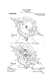
- FIG. 1 is a side elevation showing that part of the engine on which the projections containing the valves appear.
- Fig. 2 is a vertical cross sect on longitudinal of the shaft.
- Fig; 1 is an elevation, as in Flg. 3, in which, however, the front case is removed and the piston carrier is removed.
- Fig. 5, is an elevation as in Fig. 3 with the piston blades shown in a position different to that shown in Fig. 3.
- Fig. 6, is a perspective ig. 7 is a perspective view of a piston guide.
- Fig. 8 is an end elevation of a piston guide.
- Fig. 9, is a side elevation of a piston guide.
- V is a side elevation of a piston guide.
- the engine comprises a cylinder bored from three centers, one of which is central to the oval-like chamber of the piston and the other two centers are centric to this first I mentioned center and are centric to parts of the cylinder ranged with respect to a middle horizontal which arc symmetrically arline.
- he cylinder 1 is mounted on a base 2 and is closed in by an end plate 3 and an end plate 4 in a single engine such as is shown in the drawings.
- the end plate 3 1s provided with a circular groove 5 concentric with the center 6 of the cylinder this groove serves as a race for the piston blade guides as will be hereinafter explained.
- a second hub member 11 is secured to the hub memberS with the surface of one of said hub members partly overlying the the front case removed and other, the hub member 11 being for the most part of Its surfaceso far removed from the face 7 of the end plate 3 that a ring terminal 13 of one of the piston blades can freely rotate around its hub 8 with a part of the ring underlying the hub 11.
- Thering 14 of the second piston blade engages the hub 11 and through a part of its extent overlies the hub 8 and can freely rotate on its own hub.
- the piston blade 1 1 extends as an arm from the ring 14 and has a radial sweep around that part of the cylinder 10 which is concentric with the center 9 and continues in rotation in a complete circle around the center 9*, sweeping close to the surface a, b, c, and sweeping clear from the surface 0?, e, f.
- the piston blade 15 projects from the ring 13 and sweeps in close proximity to the circular surface d, e, f, and clear from the surface a, b, c.
- the terminal end of the piston blade is broad to extend from the plate 3 to the plate 4.
- the broadened end is connected to the hub by a thin arm 14: and extends from a point intermediate the surface terminals of the end 14:".
- the end 15 of the second piston blade is also broadened to extend fully between the plates 8 and 4: and the arm 15 which connects this piston terminal with the ring 13 springs from' the head close to the surface which sweeps the side terminal adjacent to surface 3.
- a carrier member 16 circular in form and having a radius equal to the-radius of the are from a to 03 and c to f engages over the hubs and inner part of the piston arms and is provided throughout the most part of its periphery with a flange that engages closely against the face of, the end member 3. It is bored near its margin with circular apertures in which engage the guide members 17 and 17.
- These are circular members capable of oscillatory motion in their sockets; they are alike and each outer wall of the groove 5 but this surface is of shorter radius than the radius of the outer wall of the groove 5 in order that the guide 17 may oscillate in the groove.
- the tie member 20 is a slot 22 cut diametrically through the guide.
- the head 14" of the piston guide reciprocates through this slot.
- the piston head is preferably provided with grooves 14 to furnish a steam packing or water packing between this surface and the surface of the cylinder adjacent to which it revolves.
- the shaft on the engine is made fast to the carrier member 16 and revolves with the carrier member; provision is made for the introduction of steam at two places diametrically opposite with the inlet port 23 controlled by oscillating valve 24 and with the inlet port 25 controlled by oscillating valve 26.
- the exhaust port 27 and the exhaust port 28 open into an exhaust chamber 29 which conducts the exhaust steam to a discharge pipe30.
- the oscillating valves 24 and 26 are-actuated by a link connection 31 to the crank 32 on the shaft and cranks 33 and 34 on the respective shafts of the oscillating valves.
- the piston blades maintain a position that is nearly diametrically opposite with respect to the axis of the main shaft; each one maintains its proper radial direction from its own center of rotation.
- a packing member comprising segments of cylinders adapted to oscillate in a cylindrical cavity and to engage slidingly a piston arm engaging between said segments, and a tie uniting said segments, said tie being provided with arched surfaces whereby it is adapted to oscillate in a guide race, substantially as described.
- a packing member comprising segments to oscillate in a cylindrical cavity and to engage slidingly a piston armengaging between said segments, and a tie uniting said segments, said tie being provided with arched surfaces whereby it is adapted to oscillate in a guide race, a casing and a groove in said casing the walls of which are adapted to engage saidarched surfaces to define the position of said packing member.
Landscapes
- Engineering & Computer Science (AREA)
- Mechanical Engineering (AREA)
- General Engineering & Computer Science (AREA)
- Transmission Devices (AREA)
Description
W. M. HOFFMAN.
ROTARY ENGINE.
APPLICATION FILED JUNE 10, 1911.
1,084,635. 1" Patented Jan. 20, 1914.
3 SHEETS-SHEET 1.
mitnrnsm v (if; @a/z/w/ my? llnumtnr w M. HOFFMAN.
ROTARY ENGINE.
APPLICATION FILED JUNE 10 1911.
1 ,0845635. 1 Patented Jan. 20, 1 914.
3 SHEETS-SHEET 2.
m nim filnumtur M @Mw WM?) Attnrnrya W. M. HOFFMAN.
ROTARY ENGINE.
APPLICATION FILED JUNE 10, 1911.
1,084,635. Patented 7311.20, 1914.
3 SHEETS-SHEET 3.
Eluumtnr Atinrnrgs view of a piston blade. I
UNITED STATES PATENT OFFICE.
WILLIAM M. HOFFMAN, OF BUFFALO, NEW YORK.
ROTARY ENGINE.
Specification of Letters Patent.
Application filed June 10, 1911.
Patented Jan. 20, 1914.
Serial No. 632,325.
exact description of the same, such as will enable others skilled in theart to whichit pertains to make and use the same, reference being had to the accompanying drawings, which form a part of this specification.
This invention relates to rotary engines.
It has for its object an improved rotary piston engine.
In the drawings :-Figure 1, 1s a side elevation showing that part of the engine on which the projections containing the valves appear. Fig. 2, is a vertical cross sect on longitudinal of the shaft. Fig. 3, 1s a side elevation with I showing the side opposite to that shown in Fig. 1. Fig; 1, is an elevation, as in Flg. 3, in which, however, the front case is removed and the piston carrier is removed. Fig. 5, is an elevation as in Fig. 3 with the piston blades shown in a position different to that shown in Fig. 3. Fig. 6, is a perspective ig. 7 is a perspective view of a piston guide. Fig. 8, is an end elevation of a piston guide. Fig. 9, is a side elevation of a piston guide. V
[The engine comprises a cylinder bored from three centers, one of which is central to the oval-like chamber of the piston and the other two centers are centric to this first I mentioned center and are centric to parts of the cylinder ranged with respect to a middle horizontal which arc symmetrically arline.
..;..;;fl: he cylinder 1 is mounted on a base 2 and is closed in by an end plate 3 and an end plate 4 in a single engine such as is shown in the drawings. The end plate 3 1s provided with a circular groove 5 concentric with the center 6 of the cylinder this groove serves as a race for the piston blade guides as will be hereinafter explained. Within the groove is a circular surface 7 upon which is secured a circular bearing hub 8 concentric with the center 9, which center 9 is concentric to the curved cylinder wall 10 at one end of'the oval chamber of the cylinder A second hub member 11 is secured to the hub memberS with the surface of one of said hub members partly overlying the the front case removed and other, the hub member 11 being for the most part of Its surfaceso far removed from the face 7 of the end plate 3 that a ring terminal 13 of one of the piston blades can freely rotate around its hub 8 with a part of the ring underlying the hub 11. Thering 14 of the second piston blade engages the hub 11 and through a part of its extent overlies the hub 8 and can freely rotate on its own hub. The piston blade 1 1 extends as an arm from the ring 14 and has a radial sweep around that part of the cylinder 10 which is concentric with the center 9 and continues in rotation in a complete circle around the center 9*, sweeping close to the surface a, b, c, and sweeping clear from the surface 0?, e, f. The piston blade 15 projects from the ring 13 and sweeps in close proximity to the circular surface d, e, f, and clear from the surface a, b, c. The terminal end of the piston blade is broad to extend from the plate 3 to the plate 4. The broadened end is connected to the hub by a thin arm 14: and extends from a point intermediate the surface terminals of the end 14:". The end 15 of the second piston blade is also broadened to extend fully between the plates 8 and 4: and the arm 15 which connects this piston terminal with the ring 13 springs from' the head close to the surface which sweeps the side terminal adjacent to surface 3. A carrier member 16 circular in form and having a radius equal to the-radius of the are from a to 03 and c to f engages over the hubs and inner part of the piston arms and is provided throughout the most part of its periphery with a flange that engages closely against the face of, the end member 3. It is bored near its margin with circular apertures in which engage the guide members 17 and 17. These are circular members capable of oscillatory motion in their sockets; they are alike and each outer wall of the groove 5 but this surface is of shorter radius than the radius of the outer wall of the groove 5 in order that the guide 17 may oscillate in the groove. The
the tie member 20 is a slot 22 cut diametrically through the guide. The head 14" of the piston guide reciprocates through this slot. The piston head is preferably provided with grooves 14 to furnish a steam packing or water packing between this surface and the surface of the cylinder adjacent to which it revolves.
The shaft on the engine is made fast to the carrier member 16 and revolves with the carrier member; provision is made for the introduction of steam at two places diametrically opposite with the inlet port 23 controlled by oscillating valve 24 and with the inlet port 25 controlled by oscillating valve 26. The exhaust port 27 and the exhaust port 28 open into an exhaust chamber 29 which conducts the exhaust steam to a discharge pipe30. The oscillating valves 24 and 26 are-actuated by a link connection 31 to the crank 32 on the shaft and cranks 33 and 34 on the respective shafts of the oscillating valves. The piston blades maintain a position that is nearly diametrically opposite with respect to the axis of the main shaft; each one maintains its proper radial direction from its own center of rotation.
What I claim is 1. In a rotary engine, a packing member comprising segments of cylinders adapted to oscillate in a cylindrical cavity and to engage slidingly a piston arm engaging between said segments, and a tie uniting said segments, said tie being provided with arched surfaces whereby it is adapted to oscillate in a guide race, substantially as described.
2. In a rotary engine, a packing member comprising segments to oscillate in a cylindrical cavity and to engage slidingly a piston armengaging between said segments, and a tie uniting said segments, said tie being provided with arched surfaces whereby it is adapted to oscillate in a guide race, a casing and a groove in said casing the walls of which are adapted to engage saidarched surfaces to define the position of said packing member.
In testimony whereof, I sign this specification in the presence of two witnesses.
WILLIAM M. HOFFMAN.
Witnesses:
STUART C. BARNES, VERA PILLMAN.
of cylinders adapted. I
Priority Applications (1)
| Application Number | Priority Date | Filing Date | Title |
|---|---|---|---|
| US63232511A US1084635A (en) | 1911-06-10 | 1911-06-10 | Rotary engine. |
Applications Claiming Priority (1)
| Application Number | Priority Date | Filing Date | Title |
|---|---|---|---|
| US63232511A US1084635A (en) | 1911-06-10 | 1911-06-10 | Rotary engine. |
Publications (1)
| Publication Number | Publication Date |
|---|---|
| US1084635A true US1084635A (en) | 1914-01-20 |
Family
ID=3152863
Family Applications (1)
| Application Number | Title | Priority Date | Filing Date |
|---|---|---|---|
| US63232511A Expired - Lifetime US1084635A (en) | 1911-06-10 | 1911-06-10 | Rotary engine. |
Country Status (1)
| Country | Link |
|---|---|
| US (1) | US1084635A (en) |
Cited By (1)
| Publication number | Priority date | Publication date | Assignee | Title |
|---|---|---|---|---|
| US6550442B2 (en) * | 2001-07-16 | 2003-04-22 | Modesto J. Garcia | Rotary machine used as a four-cycle rotary combustion engine, a compressor, a vacuum pump, a steam engine and a high pressure water motor |
-
1911
- 1911-06-10 US US63232511A patent/US1084635A/en not_active Expired - Lifetime
Cited By (1)
| Publication number | Priority date | Publication date | Assignee | Title |
|---|---|---|---|---|
| US6550442B2 (en) * | 2001-07-16 | 2003-04-22 | Modesto J. Garcia | Rotary machine used as a four-cycle rotary combustion engine, a compressor, a vacuum pump, a steam engine and a high pressure water motor |
Similar Documents
| Publication | Publication Date | Title |
|---|---|---|
| US991576A (en) | Rotary engine. | |
| US1084635A (en) | Rotary engine. | |
| US3981645A (en) | Displaced piston machine | |
| US793664A (en) | Rotary engine. | |
| US2417568A (en) | Rotary vane type pump | |
| US695006A (en) | Steam-engine. | |
| US2258379A (en) | Rotary fluid pump or motor | |
| US1319456A (en) | Rotary engine | |
| US1253716A (en) | Rotary engine. | |
| US280710A (en) | bakee | |
| US2346218A (en) | Rotary pump | |
| US1557434A (en) | Compressor | |
| US1006093A (en) | Rotary engine. | |
| US683406A (en) | Discoidal engine. | |
| US422328A (en) | Petebs | |
| US924832A (en) | Rotary engine. | |
| US1086159A (en) | Rotary engine. | |
| US1372750A (en) | Rotary engine | |
| US637986A (en) | Rotary engine. | |
| US758122A (en) | Cut-off valve for steam-engines. | |
| US867119A (en) | Rotary engine. | |
| US811103A (en) | Rotary engine. | |
| US670863A (en) | Steam-engine. | |
| US663939A (en) | Rotary engine. | |
| US262602A (en) | Rotary steam-engine |