US10843760B2 - Scooter with rotational connection - Google Patents

Scooter with rotational connection Download PDF

Info

Publication number
US10843760B2
US10843760B2 US16/202,461 US201816202461A US10843760B2 US 10843760 B2 US10843760 B2 US 10843760B2 US 201816202461 A US201816202461 A US 201816202461A US 10843760 B2 US10843760 B2 US 10843760B2
Authority
US
United States
Prior art keywords
steering mechanism
personal mobility
frame structure
mobility vehicle
leg
Prior art date
Legal status (The legal status is an assumption and is not a legal conclusion. Google has not performed a legal analysis and makes no representation as to the accuracy of the status listed.)
Active
Application number
US16/202,461
Other versions
US20190291805A1 (en
Inventor
Ian Desberg
William Griggs
Current Assignee (The listed assignees may be inaccurate. Google has not performed a legal analysis and makes no representation or warranty as to the accuracy of the list.)
Razor USA LLC
Original Assignee
Razor USA LLC
Priority date (The priority date is an assumption and is not a legal conclusion. Google has not performed a legal analysis and makes no representation as to the accuracy of the date listed.)
Filing date
Publication date
Application filed by Razor USA LLC filed Critical Razor USA LLC
Priority to US16/202,461 priority Critical patent/US10843760B2/en
Publication of US20190291805A1 publication Critical patent/US20190291805A1/en
Priority to US16/950,617 priority patent/US11383786B2/en
Application granted granted Critical
Publication of US10843760B2 publication Critical patent/US10843760B2/en
Priority to US17/861,848 priority patent/US11904979B2/en
Active legal-status Critical Current
Anticipated expiration legal-status Critical

Links

Images

Classifications

    • BPERFORMING OPERATIONS; TRANSPORTING
    • B62LAND VEHICLES FOR TRAVELLING OTHERWISE THAN ON RAILS
    • B62KCYCLES; CYCLE FRAMES; CYCLE STEERING DEVICES; RIDER-OPERATED TERMINAL CONTROLS SPECIALLY ADAPTED FOR CYCLES; CYCLE AXLE SUSPENSIONS; CYCLE SIDE-CARS, FORECARS, OR THE LIKE
    • B62K5/00Cycles with handlebars, equipped with three or more main road wheels
    • B62K5/10Cycles with handlebars, equipped with three or more main road wheels with means for inwardly inclining the vehicle body on bends
    • BPERFORMING OPERATIONS; TRANSPORTING
    • B62LAND VEHICLES FOR TRAVELLING OTHERWISE THAN ON RAILS
    • B62KCYCLES; CYCLE FRAMES; CYCLE STEERING DEVICES; RIDER-OPERATED TERMINAL CONTROLS SPECIALLY ADAPTED FOR CYCLES; CYCLE AXLE SUSPENSIONS; CYCLE SIDE-CARS, FORECARS, OR THE LIKE
    • B62K3/00Bicycles
    • B62K3/002Bicycles without a seat, i.e. the rider operating the vehicle in a standing position, e.g. non-motorized scooters; non-motorized scooters with skis or runners
    • BPERFORMING OPERATIONS; TRANSPORTING
    • B62LAND VEHICLES FOR TRAVELLING OTHERWISE THAN ON RAILS
    • B62KCYCLES; CYCLE FRAMES; CYCLE STEERING DEVICES; RIDER-OPERATED TERMINAL CONTROLS SPECIALLY ADAPTED FOR CYCLES; CYCLE AXLE SUSPENSIONS; CYCLE SIDE-CARS, FORECARS, OR THE LIKE
    • B62K5/00Cycles with handlebars, equipped with three or more main road wheels
    • B62K5/02Tricycles
    • B62K5/027Motorcycles with three wheels
    • BPERFORMING OPERATIONS; TRANSPORTING
    • B62LAND VEHICLES FOR TRAVELLING OTHERWISE THAN ON RAILS
    • B62KCYCLES; CYCLE FRAMES; CYCLE STEERING DEVICES; RIDER-OPERATED TERMINAL CONTROLS SPECIALLY ADAPTED FOR CYCLES; CYCLE AXLE SUSPENSIONS; CYCLE SIDE-CARS, FORECARS, OR THE LIKE
    • B62K5/00Cycles with handlebars, equipped with three or more main road wheels
    • B62K5/02Tricycles
    • B62K5/06Frames for tricycles
    • BPERFORMING OPERATIONS; TRANSPORTING
    • B62LAND VEHICLES FOR TRAVELLING OTHERWISE THAN ON RAILS
    • B62MRIDER PROPULSION OF WHEELED VEHICLES OR SLEDGES; POWERED PROPULSION OF SLEDGES OR SINGLE-TRACK CYCLES; TRANSMISSIONS SPECIALLY ADAPTED FOR SUCH VEHICLES
    • B62M6/00Rider propulsion of wheeled vehicles with additional source of power, e.g. combustion engine or electric motor
    • B62M6/40Rider propelled cycles with auxiliary electric motor
    • B62M6/60Rider propelled cycles with auxiliary electric motor power-driven at axle parts
    • BPERFORMING OPERATIONS; TRANSPORTING
    • B62LAND VEHICLES FOR TRAVELLING OTHERWISE THAN ON RAILS
    • B62JCYCLE SADDLES OR SEATS; AUXILIARY DEVICES OR ACCESSORIES SPECIALLY ADAPTED TO CYCLES AND NOT OTHERWISE PROVIDED FOR, e.g. ARTICLE CARRIERS OR CYCLE PROTECTORS
    • B62J43/00Arrangements of batteries
    • B62J43/10Arrangements of batteries for propulsion
    • B62J43/16Arrangements of batteries for propulsion on motorcycles or the like
    • BPERFORMING OPERATIONS; TRANSPORTING
    • B62LAND VEHICLES FOR TRAVELLING OTHERWISE THAN ON RAILS
    • B62KCYCLES; CYCLE FRAMES; CYCLE STEERING DEVICES; RIDER-OPERATED TERMINAL CONTROLS SPECIALLY ADAPTED FOR CYCLES; CYCLE AXLE SUSPENSIONS; CYCLE SIDE-CARS, FORECARS, OR THE LIKE
    • B62K2202/00Motorised scooters
    • BPERFORMING OPERATIONS; TRANSPORTING
    • B62LAND VEHICLES FOR TRAVELLING OTHERWISE THAN ON RAILS
    • B62KCYCLES; CYCLE FRAMES; CYCLE STEERING DEVICES; RIDER-OPERATED TERMINAL CONTROLS SPECIALLY ADAPTED FOR CYCLES; CYCLE AXLE SUSPENSIONS; CYCLE SIDE-CARS, FORECARS, OR THE LIKE
    • B62K2204/00Adaptations for driving cycles by electric motor
    • BPERFORMING OPERATIONS; TRANSPORTING
    • B62LAND VEHICLES FOR TRAVELLING OTHERWISE THAN ON RAILS
    • B62KCYCLES; CYCLE FRAMES; CYCLE STEERING DEVICES; RIDER-OPERATED TERMINAL CONTROLS SPECIALLY ADAPTED FOR CYCLES; CYCLE AXLE SUSPENSIONS; CYCLE SIDE-CARS, FORECARS, OR THE LIKE
    • B62K23/00Rider-operated controls specially adapted for cycles, i.e. means for initiating control operations, e.g. levers, grips
    • B62K23/02Rider-operated controls specially adapted for cycles, i.e. means for initiating control operations, e.g. levers, grips hand actuated
    • B62K23/06Levers

Abstract

A scooter device that can be propelled by side to side movement of a user is disclosed. The scooter device includes at least a first front wheel, at least a second and a third rearward located wheel, a frame structure through which the first wheel is coupled to the second and third wheels, wherein the second and third rearward located wheels are mounted in a biased direction arrangement and a steering mechanism that has a vertically ascending control member and is coupled to the first wheel such that turning of the steering mechanism achieves a turning of the first wheel, the steering mechanism further coupled to the frame structure such that the steering mechanism may be tilted relative to the frame structure. The frame structure can includes a first foot placement platform extending above the second wheel and a second foot placement platform extending above the third wheel.

Description

INCORPORATION BY REFERENCE TO ANY PRIORITY APPLICATIONS
The present application is a continuation of U.S. patent application Ser. No. 15/586,648, filed May 4, 2017, which is a continuation of U.S. patent application Ser. No. 15/019,680, filed Feb. 9, 2016, which claims the benefit of U.S. Provisional Application No. 62/114,766, filed Feb. 11, 2015, the entirety of each of which is hereby incorporated by reference herein.
BACKGROUND Field
The present disclosure relates generally to ridable vehicles and, more specifically, to a ridable scooter with a rotational connection.
Description of the Related Art
Riding on vehicles such as scooters or skateboards is a popular recreational activity. Scooters have become popular among many age groups and there are many different scooter variations and designs. Some scooters generally have at least two wheels and some type of steering mechanism. Some scooter designs include four or more wheels.
SUMMARY
Some scooters require a user to use his or her feet to push on the riding surface (e.g., the ground) to propel the scooter. It can be desirable that some scooters may be propelled without the use of a power unit (e.g., a motor). For example, it can be desirable for a scooter to be propelled through a twisting motion without requiring the user to use his or her feet to push on the riding surface and propel the scooter.
An aspect of one or more embodiments involves the realization that it is desirable to allow a user to ride on a scooter and move the scooter without the use of a motor or the user pushing off the riding surface. Therefore, the current arrangements in the prior art for ridable scooters are unsuitable and/or could be improved and/or made more desirable.
The systems, methods, and devices described herein have innovative aspects, no single one of which is indispensable or solely responsible for their desirable attributes. Without limiting the scope of the claims, some of the advantageous features of certain embodiments will now be summarized.
In one aspect, a scooter device includes a front wheel; a first rear wheel freely rotatable about a first rotation axis and pivotable about a first pivot axis; a second rear wheel freely rotatable about a second rotation axis and pivotable about a second pivot axis; a frame structure through which the front wheel is coupled to the first and second rear wheels, wherein the first and second rear wheels are mounted in a biased direction arrangement such that the first and second rear wheels are biased to return to a generally forward-facing direction; and a steering mechanism that has a steering shaft and is coupled to the front wheel such that turning the steering mechanism achieves a turning of the front wheel, the steering mechanism further coupled to the frame structure such that the steering mechanism may be tilted relative to the frame structure; wherein the frame structure includes a first foot placement platform extending above the first rear wheel and a second foot placement platform extending above the second rear wheel; and wherein, in use, the scooter is configured to be propelled by the user moving side to side, thereby shifting a portion of the weight of the user back and forth between the first and second placement platforms.
In some aspects, the scooter device further includes a power mechanism coupled to the frame structure, wherein the power mechanism drives the front wheel to propel the scooter device. In some aspects, the frame structure further includes a first rotation member and a second rotation member and the steering mechanism is connected to the second rotation member that is rotatable with respect to the first rotation member. In some aspects, an application of a lateral force on the steering mechanism results in tilting of the steering mechanism relative to the frame structure and the steering mechanism is biased to return to an initial position when the application of lateral force is removed. In some aspects, the pivot axis of each of the first and second rear wheels is inclined with respect to the first and second foot placement platforms. In some aspects, the scooter device further includes a brake assembly configured to selectively apply a braking force to the front wheel. In some aspects, the steering assembly further comprises a steering support member coupled between the steering shaft and the frame structure. In some aspects, the frame structure further includes a longitudinally-disposed support member, and the steering support member is connected to the longitudinally-disposed support member. In some aspects, the longitudinally-disposed support member comprises a first member and a second member and the first member is configured to rotate with respect to the second member. In some aspects, the second member slides within an end of the first member.
In another aspects, a personal mobility vehicle includes a front wheel; a pair of rear wheels; a frame structure having a first leg and a second leg, the first and second legs connected to a joint structure, a first platform connected to the first leg and a second platform connected to the second leg, the frame structure connecting the front wheel and the pair of rear wheels, the first platform having an upper surface configured to support a first foot of the user and the second platform having an upper surface configured to support a second foot of the user; and a steering mechanism having a steering shaft, the steering mechanism connected to the front wheel such that turning the steering mechanism turns the front wheel, the steering mechanism further connected to the joint structure such that the steering mechanism may be tilted relative to the frame structure.
In some aspects, the joint structure comprises a first member and a second member and the second member is configured to rotate with respect to the first member. In some aspects, the second member slides within an end of the first member. In some aspects, the steering mechanism further comprises a handlebar including two handgrip portions. In some aspects, the pair of rear wheels are caster wheels mounted in a forward tilted arrangement with respect to the first and second platforms. In some aspects, the personal mobility vehicle further includes a power mechanism configured to provide power to the front wheel. In some aspects, the power mechanism includes an electric motor that drives the front wheel.
In yet another aspect, a scooter includes a front wheel; a first rear wheel freely rotatable about a first rotation axis and pivotable about a first pivot axis; a second rear wheel freely rotatable about a second rotation axis and pivotable about a second pivot axis; a frame structure having a first leg and a second leg, the first and second legs connected to a joint structure, a first foot support platform connected to the first leg and a second foot support platform connected to the second leg, the frame structure connecting the front wheel and the first and second rear wheels; and a steering mechanism having a steering shaft connected to the joint structure such that the steering mechanism may be tilted relative to the frame structure, the steering mechanism connected to the front wheel; wherein, in use, the scooter is propelled by side to side movement of a user.
In some aspects, the scooter further includes a power mechanism configured to provide power to the front wheel. In some aspects, the power mechanism includes an electric motor that drives the front wheel.
BRIEF DESCRIPTION OF THE DRAWINGS
Throughout the drawings, reference numbers can be reused to indicate general correspondence between reference elements. The drawings are provided to illustrate example embodiments described herein and are not intended to limit the scope of the disclosure.
FIG. 1 illustrates a side perspective view of a scooter device in accordance with an embodiment.
FIG. 2 illustrates a side perspective view of a scooter device in accordance with another embodiment.
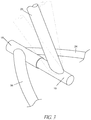
FIG. 3 illustrates a rotational connection of a handlebar member of the scooter device shown in FIG. 1 and FIG. 2.
FIG. 4 illustrates a schematic view of a scooter device that includes a seat.
DETAILED DESCRIPTION OF CERTAIN EMBODIMENTS
Reference will now be made in detail to various embodiments of the present technology, which relates to various personal mobility devices, such as scooters. Although certain specific embodiments of the present technology are described, the present technology is not limited to these embodiments. On the contrary, these described embodiments are merely illustrative of the present technology, and the present technology is intended to also cover alternatives, modifications, and equivalents. Furthermore, in the following detailed description, numerous specific details are set forth in order to provide a thorough understanding of the present technology. However, it will be recognized by one of ordinary skill in the art that embodiments may be practiced without these specific details. In some instances, well known methods, procedures, compounds, compositions and mechanisms have not been described in detail as not to unnecessarily obscure aspects of embodiments of the present technology.
For the purposes of this disclosure, embodiments of personal mobility vehicles will be referred to as “scooters”, but it will be understood by those with ordinary skill in the art that the present disclosure extends beyond the specifically disclosed embodiments and references to scooters to other alternative embodiments and/or uses of the invention and modifications and equivalents thereof. In particular, while the present vehicles and related methods have been described in the context of particularly preferred embodiments as it relates to scooters, the skilled artisan will appreciate, in view of the present disclosure, that certain advantages, features and aspects of the systems and methods may be realized in a variety of other applications, including personal mobility vehicles other than scooters and/or scooters with different arrangements of front and rear wheels.
In a preferred embodiment, a scooter device 10 may include a frame structure 20 that is coupled to a steering mechanism 50. In some embodiments, the frame structure 20 is connected with at least two rear wheels 22, 32. The frame structure 20 is connected to the steering mechanism 50 with a steering mechanism support member 25. The frame structure 20 may include a joint structure 40 from which legs 24 and 34 extend. In the embodiment of FIG. 1, a longitudinally disposed support is configured as multiple rotation members 18, 19 or other structure that connects the steering mechanism support member 25 and the legs 24, 34. The first and second rotation members 18, 19 are preferably configured such that the second rotation member 19 rotates with respect to the first rotation member 18, as will be discussed in greater detail below. In some embodiments, the second rotation member 19 may fit or slide within an end of the first rotation member 18. For example, as shown, the first and second rotation members 18, 19 can be generally coaxially aligned. Support member 25 may be non-movably coupled to steering mechanism 50 (shown in FIGS. 1-2) or movably coupled through a pivot or otherwise coupled.
The steering mechanism 50 includes a steering shaft 54 that is coupled to a front wheel 12 on one end and ascends to a handlebar 53 at its other end. In some embodiments, the steering shaft 54 is generally parallel to a vertical axis. The steering shaft may include multiple (telescoping or otherwise configured) sections and a height adjustment mechanism. The handlebar 53 may include two handgrip portions 56, 57 that the user may use to steer and control the scooter 10. As shown, the handlebar 53 may include one or more hand brakes 58, 59 that the user may actuate to brake the scooter. The hand brakes 58, 59 can be operably connected (e.g., via a cable) with a brake assembly (not shown) that is configured to engage to brake the scooter. For example, the brake assembly can be configured to engage with one of the wheels.
The scooter device 10 can include a location for the user to sit (such as a seat 70 as illustrated in FIG. 4) or stand. For example, the scooter device 10 may have a plurality of user platforms 42, 52 that are coupled to the legs 24, 34. As shown, in some embodiments, the platforms 42, 52 of FIGS. 1-2 extend substantially over the rear wheels 22, 32. The platforms 42, 52 provide surface areas on which a user can place their feet to ride on the scooter and/or perform stunts with the scooter.
In some embodiments, the rear wheels 22, 32 are caster wheels (and thus can also be called “rear swivel caster wheels”). In some embodiments, the rear wheels 22, 32 each comprise a wheel, fork, and shaft. The two rear wheels 22, 32 are preferably mounted in a forward tilted caster arrangement. This arrangement achieves a wheel that is capable of turning via rotation about its mounting shaft, yet which self-returns to the line of direction at which it is mounted. In some embodiments, the rear wheels 22, 32 are each tilted, relative to vertical, at least about: 5°, 10°, 15°, 20°, 25°, or otherwise.
The rear wheels 22, 32 may have a centering mechanism, which is configured to bias the rear wheels to a neutral (e.g., forward) steering position. For example, a spring action device may be mounted between the rear wheels 22, 32 and some portion of the user support platforms 42, 52 of the scooter. This can provide rotational resistance to the rear wheels 22, 32 relative to the platforms 42, 52. In certain embodiments, centering of the rear wheels 22, 32 may be provided by a biasing mechanism (e.g., torsion spring arrangement, such as a helical torsion spring). In these embodiments, the spring provides resistance to pivoting or turning of the fork about its turning axis. The biasing mechanism may also provide rotational resistance and a biasing force on the rear wheels to return the rear wheels to their neutral steering position when the scooter is being propelled by the user in a forward direction. Additional details regarding such centering wheels and/or biasing mechanisms can be found, for example, in U.S. Pat. No. 7,195,259, which is hereby incorporated by reference in its entirety.
As discussed above, the support member 25 connects the steering mechanism 50 to the frame structure 20. In some embodiments, the support member 25 may be fixedly coupled to the frame structure 20. For example the support member 25 may be welded or bolted to the frame structure 20.
In certain implementations, the support member 25 may be dynamically connected to the frame structure 20. For example, the support member 25 can connect with the second rotation member 19, which can be configured to move (e.g., rotate) relative to the first rotation member 18 of the frame structure 20. In some embodiments, the first and/or second rotation member 18, 19 includes a biased cam or the like that permits movement of the support member 25 with respect to the legs 24, 34 of the frame structure 20. In some variants, some or all of the support member 25 comprises a generally rigid, yet flexible, material with elastic properties, such as fiberglass, flexible metal, polyurethane or the like. The generally rigid, yet flexible, support member can permit the steering mechanism 25 to move relative to the legs 24, 34, which can permit a user to lean the steering mechanism 50 into a curve.
As shown in FIG. 3, the second rotation member 19 preferably permits movement (e.g., side-to-side movement) of the support member 25 and the steering mechanism 50 in response to a displacement force applied by the user, such as a generally lateral force that the user applies via the handgrip portions 56, 57. In some embodiments, the second rotation member 19 is configured to return to a rest position (e.g., an initial position) in the absence of the displacement force. In some embodiments, in the rest position, the steering shaft 54 is generally parallel to a vertical axis, such as is shown in FIGS. 1 and 2.
In certain implementations, since the support member 25 is coupled to the steering mechanism 50 and to the second rotation member 19 (which is configured to move relative to the first rotation member 18 of the frame structure 20), the steering mechanism 50 can be moved (e.g., tilted) relative to the legs 24, 34 and the user platforms 42, 52. This can permit a user to adjust the steering mechanism 50, such as to lean the steering mechanism 50 into a turn, etc. In certain embodiments, the steering mechanism 50 is configured to tilt, from a vertical position and in a first direction (e.g., right), at least about: 30°, 40°, 50°, 60°, 75°, or otherwise. In various embodiments, the steering mechanism 50 is configured to tilt, from a vertical position and in a second direction (e.g., right), at least about: 30°, 40°, 50°, 60°, 75°, or otherwise. In some implementations, the steering mechanism 50 tilts independently of frame structure 20. For example, tilting of the steering mechanism 50 up to at least about 30° from vertical does not substantially move the frame structure 20. In some variants, tilting of the steering mechanism 50 up to at least about 40° from vertical does not result in either of rear wheels 22, 32 being raised off of the riding surface (e.g., ground).
As shown in FIGS. 1 and 2, rear wheels 22, 32 may be mounted below the foot or user platforms 42, 52. The rear wheels 22, 32 are preferably mounted to the platforms 42, 52 such that, in response to the user leaning the steering mechanism 50 to its right side (with respect to the advancing direction of the scooter), the rear wheels 22, 32 will roll to the right so that the user can turn the scooter device 10 to the right. Alternatively, in response to the user leaning the steering mechanism 50 to its left side (with respect to the advancing direction of the scooter), the rear wheels 22, 32 will roll to the left with respect to the advancing direction so that the user can turn to the left.
In some embodiments, to propel the scooter 10, a user shifts his or her weight from side to side on the platforms 42, 52 of the frame structure 20. This can apply a force to the frame structure 20 that results in the frame structure 20 moving relative to the steering mechanism 50. For example, such movement of the frame structure 20 can cause the steering mechanism 50 to rotate relative to the frame structure 20. As the user moves the frame structure 20 side to side due to the application of force on the platforms 42, 52, the rear wheels 22, 32 will make rolling angles with respect to the advancing direction or direction of travel. As a result, the user can propel the scooter 10 forward by twisting his or her body side to side without moving his feet from the platforms 42, 52. Alternatively, or in addition to the propulsion method discussed above, the user may use his feet to propel the scooter 10 by, for example, pushing against the ground.
In some embodiments, the scooter 10 may include a power mechanism 55, as shown in FIG. 1. The power mechanism 55 may be configured to provide power to front wheel 12 to propel the scooter without the user needing to push with his or her feet and/or without needing to move the frame structure side to side as described above. In some embodiments, the power mechanism 55 includes an electric motor 23 that drives the front wheel 12 using a belt. In many instances, the electric motor is a 250 W variable speed electric motor, though any of a variety of electric motors can be used. The power mechanism 55 preferably includes a battery that may be used to power the electric motor 23.
As shown, the legs 24, 34 can be connected by the first rotation portion 18. In some embodiments, the legs 24, 34 are connected by only the first rotation portion 18. In some embodiments, as shown in FIG. 2, additional support members, such as shaft 21 may run between the legs 24, 34 to provide additional stability to the scooter 10.
Terms of orientation used herein, such as “top”, “bottom”, “upward”, “downward”, “lower”, “front”, “frontward”, “rear”, “rearward”, and “end” are used to simplify the description of the context of the illustrated embodiments. Likewise, terms of sequence, such as “first” and “second”, are used to simplify the description of the illustrated embodiments. However, other orientation and sequences are possible, and the present disclosure should not be limited to the illustrated orientation(s). Those skilled in the art will appreciate that other orientations of the various components are possible.
Conditional language, such as “can,” “could,” “might,” or “may,” unless specifically stated otherwise, or otherwise understood within the context as used, is generally intended to convey that certain embodiments include or do not include certain features, elements, and/or steps. Thus, such conditional language is not generally intended to imply that features, elements, and/or steps are in any way required for one or more embodiments.
Conjunctive language, such as the phrase “at least one of X, Y, and Z,” unless specifically stated otherwise, is otherwise understood with the context as used in general to convey that an item, term, etc. may be either X, Y, or Z. Thus, such conjunctive language is not generally intended to imply that certain embodiments require the presence of at least one of X, at least one of Y, and at least one of Z.
The terms “approximately,” “about,” and “substantially” as used herein represent an amount close to the stated amount that still performs a desired function or achieves a desired result. For example, in some embodiments, as the context may permit, the terms “approximately”, “about”, and “substantially” may refer to an amount that is within less than or equal to 10% of the stated amount. The term “generally” as used herein represents a value, amount, or characteristic that predominantly includes or tends toward a particular value, amount, or characteristic. As an example, in certain embodiments, as the context may permit, the term “generally parallel” can refer to something that departs from exactly parallel by less than or equal to 20 degrees.
Unless otherwise explicitly stated, articles such as “a” or “an” should generally be interpreted to include one or more described items. Accordingly, phrases such as “a device configured to” are intended to include one or more recited devices. Such one or more recited devices can also be collectively configured to carry out the stated recitations. For example, “a processor configured to carry out recitations A, B, and C” can include a first processor configured to carry out recitation A working in conjunction with a second processor configured to carry out recitations B and C.
The terms “comprising,” “including,” “having,” and the like are synonymous and are used inclusively, in an open-ended fashion, and do not exclude additional elements, features, acts, operations, and so forth. Likewise, the terms “some,” “certain,” and the like are synonymous and are used in an open-ended fashion. Also, the term “or” is used in its inclusive sense (and not in its exclusive sense) so that when used, for example, to connect a list of elements, the term “or” means one, some, or all of the elements in the list.
Overall, the language of the claims is to be interpreted broadly based on the language employed in the claims. The language of the claims is not to be limited to the non-exclusive embodiments and examples that are illustrated and described in this disclosure, or that are discussed during the prosecution of the application.
Although this invention has been disclosed in the context of certain preferred embodiments and examples, it will be understood by those skilled in the art that the present disclosure extends beyond the specifically disclosed embodiments to other alternative embodiments and/or uses of the invention and obvious modifications and equivalents thereof. In particular, while the present systems and methods have been described in the context of particularly preferred embodiments, the skilled artisan will appreciate, in view of the present disclosure, that certain advantages, features and aspects of the systems and methods may be realized in a variety of other applications, many of which have been noted above. Various features and aspects of the disclosed embodiments can be combined with or substituted for one another in order to form varying modes of the conveyor. The scope of this disclosure should not be limited by the particular disclosed embodiments described herein.
Additionally, it is contemplated that various aspects and features of the invention described can be practiced separately, combined together, or substituted for one another, and that a variety of combination and subcombinations of the features and aspects can be made and still fall within the scope of the invention. Certain features that are described in this disclosure in the context of separate implementations can also be implemented in combination in a single implementation. Conversely, various features that are described in the context of a single implementation can also be implemented in multiple implementations separately or in any suitable subcombination. Although features may be described above as acting in certain combinations, one or more features from a claimed combination can, in some cases, be excised from the combination, and the combination may be claimed as any subcombination or variation of any subcombination.
Moreover, while operations may be depicted in the drawings or described in the specification in a particular order, such operations need not be performed in the particular order shown or in sequential order, and all operations need not be performed, to achieve the desirable results. Other operations that are not depicted or described can be incorporated in the example methods and processes. For example, one or more additional operations can be performed before, after, simultaneously, or between any of the described operations. Further, the operations may be rearranged or reordered in other implementations. Also, the separation of various system components in the implementations described above should not be understood as requiring such separation in all implementations, and it should be understood that the described components and systems can generally be integrated together in a single product or packaged into multiple products. Additionally, other implementations are within the scope of this disclosure.
Some embodiments have been described in connection with the accompanying drawings. The figures are drawn to scale, but such scale should not be limiting, since dimensions and proportions other than what are shown are contemplated and are within the scope of the disclosed invention. Distances, angles, etc. are merely illustrative and do not necessarily bear an exact relationship to actual dimensions and layout of the devices illustrated. Components can be added, removed, and/or rearranged. Further, the disclosure herein of any particular feature, aspect, method, property, characteristic, quality, attribute, element, or the like in connection with various embodiments can be used in all other embodiments set forth herein. Additionally, any methods described herein may be practiced using any device suitable for performing the recited steps.
In summary, various embodiments and examples of personal mobility devices, such as scooters, have been disclosed. Although the devices have been disclosed in the context of those embodiments and examples, this disclosure extends beyond the specifically disclosed embodiments to other alternative embodiments and/or other uses of the embodiments, as well as to certain modifications and equivalents thereof. This disclosure expressly contemplates that various features and aspects of the disclosed embodiments can be combined with, or substituted for, one another. Thus, the scope of this disclosure should not be limited by the particular embodiments described above, but should be determined only by a fair reading of the claims that follow.

Claims (20)

What is claimed is:
1. A personal mobility vehicle comprising:
a front wheel;
a plurality of rear wheels, each of the plurality of rear wheels being rotatable about a respective rotation axis and pivotable about a respective pivot axis;
a frame structure comprising a longitudinally-disposed member, a first leg, a second leg, a first platform, and a second platform, each of the first and second platforms being configured to support a user's foot, wherein the longitudinally-disposed member comprises a first member and a second member, the second member being rotatable relative to the first member, and wherein the first and second legs are fixed relative to each other;
a seat;
a steering mechanism comprising a steering support member, the steering support member being connected to the longitudinally-disposed member of the frame structure; and
a power mechanism comprising a motor configured to drive the front wheel.
2. The personal mobility vehicle of claim 1, wherein the first platform is connected to the first leg and the second platform is connected to the second leg.
3. The personal mobility vehicle of claim 1, wherein the first leg and the second leg are connected by only the first member.
4. The personal mobility vehicle of claim 1, further comprising a shaft extending between the first leg and the second leg.
5. The personal mobility vehicle of claim 1, wherein an application of a lateral force on the steering mechanism causes tilting of the steering mechanism relative to the frame structure.
6. The personal mobility vehicle of claim 5, wherein the steering mechanism is biased to return to an initial position when the application of the lateral force is removed.
7. The personal mobility vehicle of claim 1, wherein a portion of the second member slides within a portion of the first member.
8. A personal mobility vehicle comprising:
a front wheel;
a plurality of rear wheels, each of the plurality of rear wheels being rotatable about a respective rotation axis and pivotable about a respective pivot axis;
a frame structure comprising a longitudinally-disposed member, a first platform, and a second platform, each of the first and second platforms being configured to support a user's foot, wherein the longitudinally-disposed member comprises a first member and a second member, the second member being rotatable relative to the first member;
a laterally extending support connected to the frame structure, the support configured to inhibit relative movement of the first and second platforms;
a seat;
a steering mechanism comprising a steering support member, the steering support member being connected to the longitudinally-disposed member of the frame structure; and
a power mechanism comprising a motor configured to drive the front wheel.
9. The personal mobility vehicle of claim 8, wherein an application of a lateral force on the steering mechanism causes tilting of the steering mechanism relative to the frame structure.
10. The personal mobility vehicle of claim 9, wherein the steering mechanism is biased to return to an initial position when the application of the lateral force is removed.
11. The personal mobility vehicle of claim 8, wherein a portion of the second member slides within a portion of the first member.
12. The personal mobility vehicle of claim 8, wherein the first member and the second member are coaxially aligned.
13. The personal mobility vehicle of claim 8, wherein the steering mechanism further comprises a handlebar including a handgrip portion.
14. A personal mobility vehicle comprising:
a front wheel;
a plurality of rear wheels, each of the plurality of rear wheels being rotatable about a respective rotation axis and pivotable about a respective pivot axis;
a frame structure comprising a longitudinally-disposed member, a first platform, and a second platform, each of the platforms being configured to support a user's foot, wherein the longitudinally-disposed member comprises a first member and a second member, the second member being rotatable relative to the first member;
a seat;
a steering mechanism comprising a steering support member, wherein the steering support member couples the steering mechanism to the frame structure, the steering support member being connected to the longitudinally-disposed member, wherein the steering mechanism is configured to rotate and tilt relative to the frame structure; and
a power mechanism comprising a motor configured to drive the front wheel.
15. The personal mobility vehicle of claim 14, further comprising a first leg and a second leg.
16. The personal mobility vehicle of claim 15, wherein the first platform is connected to the first leg and the second platform is connected to the second leg.
17. The personal mobility vehicle of claim 15, wherein the first leg and the second leg are connected by only the first member.
18. The personal mobility vehicle of claim 15, wherein the first and second legs extend rearward at an angle.
19. The personal mobility vehicle of claim 14, wherein an application of a lateral force on the steering mechanism causes tilting of the steering mechanism relative to the frame structure.
20. The personal mobility vehicle of claim 19, wherein the steering mechanism is biased to return to an initial position when the application of the lateral force is removed.
US16/202,461 2015-02-11 2018-11-28 Scooter with rotational connection Active US10843760B2 (en)

Priority Applications (3)

Application Number Priority Date Filing Date Title
US16/202,461 US10843760B2 (en) 2015-02-11 2018-11-28 Scooter with rotational connection
US16/950,617 US11383786B2 (en) 2015-02-11 2020-11-17 Scooter with rotational connection
US17/861,848 US11904979B2 (en) 2015-02-11 2022-07-11 Scooter with rotational connection

Applications Claiming Priority (4)

Application Number Priority Date Filing Date Title
US201562114766P 2015-02-11 2015-02-11
US15/019,680 US9643679B2 (en) 2015-02-11 2016-02-09 Scooter with rotational connection
US15/586,648 US10144476B2 (en) 2015-02-11 2017-05-04 Scooter with rotational connection
US16/202,461 US10843760B2 (en) 2015-02-11 2018-11-28 Scooter with rotational connection

Related Parent Applications (1)

Application Number Title Priority Date Filing Date
US15/586,648 Continuation US10144476B2 (en) 2015-02-11 2017-05-04 Scooter with rotational connection

Related Child Applications (1)

Application Number Title Priority Date Filing Date
US16/950,617 Continuation US11383786B2 (en) 2015-02-11 2020-11-17 Scooter with rotational connection

Publications (2)

Publication Number Publication Date
US20190291805A1 US20190291805A1 (en) 2019-09-26
US10843760B2 true US10843760B2 (en) 2020-11-24

Family

ID=56565689

Family Applications (5)

Application Number Title Priority Date Filing Date
US15/019,680 Active US9643679B2 (en) 2015-02-11 2016-02-09 Scooter with rotational connection
US15/586,648 Active 2036-02-27 US10144476B2 (en) 2015-02-11 2017-05-04 Scooter with rotational connection
US16/202,461 Active US10843760B2 (en) 2015-02-11 2018-11-28 Scooter with rotational connection
US16/950,617 Active US11383786B2 (en) 2015-02-11 2020-11-17 Scooter with rotational connection
US17/861,848 Active US11904979B2 (en) 2015-02-11 2022-07-11 Scooter with rotational connection

Family Applications Before (2)

Application Number Title Priority Date Filing Date
US15/019,680 Active US9643679B2 (en) 2015-02-11 2016-02-09 Scooter with rotational connection
US15/586,648 Active 2036-02-27 US10144476B2 (en) 2015-02-11 2017-05-04 Scooter with rotational connection

Family Applications After (2)

Application Number Title Priority Date Filing Date
US16/950,617 Active US11383786B2 (en) 2015-02-11 2020-11-17 Scooter with rotational connection
US17/861,848 Active US11904979B2 (en) 2015-02-11 2022-07-11 Scooter with rotational connection

Country Status (5)

Country Link
US (5) US9643679B2 (en)
EP (1) EP3256372B1 (en)
JP (2) JP6626510B2 (en)
CN (1) CN107406116B (en)
WO (1) WO2016130587A1 (en)

Cited By (2)

* Cited by examiner, † Cited by third party
Publication number Priority date Publication date Assignee Title
USD956142S1 (en) 2017-09-12 2022-06-28 Razor Usa Llc Personal mobility vehicle
US11383786B2 (en) 2015-02-11 2022-07-12 Razor Usa Llc Scooter with rotational connection

Families Citing this family (12)

* Cited by examiner, † Cited by third party
Publication number Priority date Publication date Assignee Title
US10399632B2 (en) 2014-12-18 2019-09-03 The Glorious Empire, Llc Adjustable rear wheel hood brake/stop system for free style kick scooters
US9783260B2 (en) * 2014-12-18 2017-10-10 Andrew Broussard Adjustable rear wheel hood brake/stop system for free style kick scooters
US9889368B1 (en) * 2016-09-02 2018-02-13 Shane Chen Personal transportation device
CN206644930U (en) * 2017-03-03 2017-11-17 国星智能(深圳)科技有限公司 A kind of Quick Release conversion equipment of carriage for children
DE102018000114B4 (en) * 2018-01-10 2021-01-28 Andreas ten Haaft Vehicle multi-lane and tiltable, with push and ride properties
USD885987S1 (en) 2018-04-17 2020-06-02 Razor Usa Llc Personal mobility vehicle
WO2020204869A1 (en) * 2019-04-01 2020-10-08 Иван Иванович КОТУРБАЧ Adaptive three-wheeled electric scooter
EP4013669A4 (en) * 2019-08-15 2023-08-16 DGL Group Ltd. Three-wheeled power drift scooter
US20210275869A1 (en) * 2020-03-05 2021-09-09 Connie Dumas Bass Lower body training assist device
JP6915179B1 (en) * 2020-05-01 2021-08-04 本田技研工業株式会社 vehicle
CN113212622A (en) * 2021-06-24 2021-08-06 深圳百客电子商务有限公司 Balance car, control method thereof and kart taking balance car as power
US11827308B2 (en) * 2021-08-31 2023-11-28 Honda Motor Co., Ltd. Three wheeled electric cargo transporter

Citations (63)

* Cited by examiner, † Cited by third party
Publication number Priority date Publication date Assignee Title
US4071261A (en) 1976-10-01 1978-01-31 General Motors Corporation Lock bar for cambering vehicle
US4087106A (en) 1975-05-19 1978-05-02 General Motors Corporation Cambering vehicle
US4123079A (en) 1977-03-21 1978-10-31 General Motors Corporation Occupant propelled cambering vehicle
US4165093A (en) 1977-03-21 1979-08-21 General Motors Corporation Occupant propelled cambering vehicle
US4540192A (en) 1983-12-27 1985-09-10 Shelton L Harvey Three-wheeled scooter-type vehicle
US5039121A (en) 1989-10-11 1991-08-13 Rick L. Hardin Tri-skater
USD338433S (en) 1991-06-14 1993-08-17 Crooks Sr John H Adult tricycle
FR2689082A1 (en) 1992-03-30 1993-10-01 Girardi Philippe Small tricycle scooter which inclines on bends - carries two rear wheels on pivoting arms from steering column with links to articulated cross-beam
US5551717A (en) 1992-04-09 1996-09-03 De Courcey Milne; John Sports conveyance
USD449017S1 (en) 2000-11-07 2001-10-09 Shui-Te Tsai Electric tricycle
USD450631S1 (en) 2001-02-20 2001-11-20 Apax Vehicle Developments Inc. Tricycle
US20020063411A1 (en) 2000-11-29 2002-05-30 Pin-Chieh Feng Foldable tricycle
US20020063406A1 (en) 2000-11-29 2002-05-30 Pin-Chieh Feng Footboard of tricycle
JP2002325878A (en) 2001-03-01 2002-11-12 Jd Japan Kk Tricycle skater
US6531838B2 (en) 2000-12-21 2003-03-11 Mobile Transport Technologies, Inc. Front-wheel-mounted electric motor for a wheeled vehicle
US20030188906A1 (en) 2002-04-09 2003-10-09 Todd Bank Swing-steering system for three-wheeled vehicles
JP2003532571A (en) 1999-11-05 2003-11-05 トリッケ テク インコーポレーテッド Cambering vehicle and mechanism thereof
USD483821S1 (en) 2002-12-18 2003-12-16 Lien-Chuan Yang Exercise bike with three wheels
US20040094925A1 (en) 2003-06-23 2004-05-20 Unique Forces Company Limited Cambering vehicle
US20050035570A1 (en) 2003-08-12 2005-02-17 Chu Kuo Yi Folding bicycle structure
USD524193S1 (en) 2005-04-29 2006-07-04 Jae Hyun Hong Frame of tricycle
USD540400S1 (en) 2004-09-24 2007-04-10 Zap Three-wheeled vehicle
USD553198S1 (en) 2005-12-19 2007-10-16 Play And Run Natural S.A. De C.V. Three-wheeled velocipede without pedals
KR200438635Y1 (en) 2007-01-23 2008-02-28 주식회사 슬로비 A Trike Having A Handle-stem With Independent Tilting Means
WO2009041933A2 (en) 2007-09-21 2009-04-02 Razor Usa, Llc Side movement propelled scooter device having expanded foot platform
US7549655B2 (en) 2007-01-30 2009-06-23 Jeeng-Neng Fan Scooter
KR20100007115A (en) 2008-07-11 2010-01-22 주식회사 슬로비 Foothole attaching and detaching type kick board
JP3157958U (en) 2009-08-10 2010-03-04 正修科技大學 Body link mechanism
US7681895B2 (en) 2006-01-21 2010-03-23 Shane Chen Side movement propelled scooter device having expanded foot platform
USD622639S1 (en) 2009-10-20 2010-08-31 Eric Lee Brockmeyer Tricycle
US20100234186A1 (en) 2009-03-13 2010-09-16 Jeeng-Neng Fan Skate fitness car
USD626038S1 (en) 2009-04-12 2010-10-26 Ying-Yi Li Tricycle
USD630158S1 (en) 2010-02-16 2011-01-04 Huffy Corporation Child vehicle
US20110031709A1 (en) 2007-12-28 2011-02-10 Mski Corp. Tricycle kick board
US20110089656A1 (en) 2009-10-15 2011-04-21 Po-Lin Chiu Manual-swinging scooter
US20110298193A1 (en) 2010-06-04 2011-12-08 Hsin Lung Accessories Co., Ltd. skate car structure
USD654542S1 (en) 2011-06-01 2012-02-21 Po-Lin Chiu Scooter
US20120043733A1 (en) 2010-08-19 2012-02-23 Tong-Pei Tsai Wiggling freewheeled vehicle
USD668186S1 (en) 2011-03-31 2012-10-02 Usine GTX, Inc. Tricycle
USD680175S1 (en) 2011-09-12 2013-04-16 Funtastic Limited Tricycle
US20140070508A1 (en) 2012-09-11 2014-03-13 Hideyasu Yamabe Kick skater
USD710950S1 (en) 2013-03-15 2014-08-12 Radio Flyer Inc. Ride-on vehicle
US8807581B2 (en) 2012-03-30 2014-08-19 Yvolve Sports Ltd Head tube reset mechanism for a scooter
US20150068828A1 (en) 2013-09-10 2015-03-12 Egological Mobility Solutions Inc. Foldable electric vehicle
USD735812S1 (en) 2014-07-03 2015-08-04 Urban626, Llc Motorized scooter
USD739310S1 (en) 2013-11-26 2015-09-22 Richard David Barnaby Latham Tricycle
US20150266530A1 (en) 2014-03-19 2015-09-24 Yvolve Sports Ltd Swing scooter
USD745608S1 (en) 2014-10-29 2015-12-15 Zhejiang Jinbang Sports Equipment Co., Ltd. Adjustable three wheel drifting scooter
WO2016130587A1 (en) 2015-02-11 2016-08-18 Razor Usa Llc Scooter with rotational connection
USD774979S1 (en) 2015-05-28 2016-12-27 Urban626, Llc Motorized scooter
USD774969S1 (en) 2015-02-24 2016-12-27 Martin Angelov Angelov Folding pedal powered tricycle
US20170029060A1 (en) 2014-04-11 2017-02-02 Mski Corporation Tricycle kick scooter
USD782942S1 (en) 2016-02-08 2017-04-04 Michael Trifaro Adult tricycle
USD787378S1 (en) 2016-02-09 2017-05-23 Radio Flyer Inc. Stroller tricycle
US20170313375A1 (en) 2014-12-31 2017-11-02 Jong-ho Lee Tilting-capable three-wheeled boarding vehicle
US20170361892A1 (en) 2014-12-11 2017-12-21 Edge Brands Ltd. Scooter with mechanical assemblies
US9873476B2 (en) 2015-05-29 2018-01-23 Urban626, Llc Foldable electric vehicle
US20180072366A1 (en) 2016-09-13 2018-03-15 Toyota Jidosha Kabushiki Kaisha Traveling apparatus
USD824291S1 (en) 2017-05-08 2018-07-31 Melody Hsieh Ergonomic tricycle
USD828233S1 (en) 2015-03-06 2018-09-11 Radio Flyer Inc. Ride-on tricycle
USD845837S1 (en) 2017-11-03 2019-04-16 Relync Tech Ltd. Folding electric tricycle
USD855116S1 (en) 2017-09-12 2019-07-30 Razor Usa Llc Personal mobility vehicle
USD885987S1 (en) 2018-04-17 2020-06-02 Razor Usa Llc Personal mobility vehicle

Family Cites Families (26)

* Cited by examiner, † Cited by third party
Publication number Priority date Publication date Assignee Title
US4050713A (en) * 1976-09-28 1977-09-27 General Motors Corporation Cambering device for cambering vehicle
US4065146A (en) * 1976-09-28 1977-12-27 General Motors Corporation Cambering device for cambering vehicle
US4050712A (en) * 1976-09-28 1977-09-27 General Motors Corporation Cambering device for cambering vehicle
JP3157958B2 (en) 1993-07-13 2001-04-23 ダイハツ工業株式会社 Leading vehicle recognition method
US20030042058A1 (en) * 2001-08-28 2003-03-06 Shane Chen Detachable motor for scooter
EP1511541B1 (en) 2002-05-01 2007-11-07 Decolee Co., Ltd. Skateboard with direction-caster
USD484073S1 (en) 2002-07-17 2003-12-23 Razor Usa Llc Tricycle
USD498709S1 (en) 2003-08-04 2004-11-23 Razor Usa Llc Rear steering tricycle
US7597334B2 (en) * 2006-01-21 2009-10-06 Shane Chen Sideways movement propelled scooter device
CN201002682Y (en) * 2007-01-23 2008-01-09 美国锐哲有限公司 Sliding vehicle driven by user side movement
US8157274B2 (en) 2009-01-06 2012-04-17 Shane Chen Torsionally flexible connecting structure for transportation device
KR101158493B1 (en) * 2009-04-10 2012-06-21 오상우 Kick board
KR20100134262A (en) * 2009-06-15 2010-12-23 구본하 Playing apparatus
USD645925S1 (en) 2009-09-03 2011-09-27 Razor Usa Llc Skateboard
KR20120013809A (en) * 2010-08-06 2012-02-15 주식회사 하이트라이더 The roller-ski of inline-board
USD693414S1 (en) 2012-03-15 2013-11-12 Razor Usa Llc Electric scooter
US9168965B2 (en) 2012-10-02 2015-10-27 Bravo Sports Electric scooter assemblies
USD810836S1 (en) 2015-10-29 2018-02-20 Razor Usa Llc Electric scooter
USD793481S1 (en) 2016-05-17 2017-08-01 Razor Usa Llc Drifting kart
USD932948S1 (en) 2019-08-15 2021-10-12 Harley-Davidson Motor Company Group, LLC Motorcycle
USD943030S1 (en) 2019-11-28 2022-02-08 Shenzhen Ridetech Electronics Co., Ltd Electric folding scooter
TWD210839S (en) 2020-01-22 2021-04-01 大陸商納恩博(北京)科技有限公司 Scooter
USD940599S1 (en) 2020-01-24 2022-01-11 Super73, Inc. Powered motorbike
USD940600S1 (en) 2020-01-24 2022-01-11 Super 73, Inc. Motorbike frame with gusset joint
KR20220001304A (en) 2020-06-29 2022-01-05 현대자동차주식회사 Personal mobility and control method for the same
USD938864S1 (en) 2021-04-01 2021-12-21 Yuantao Tong Bracket for bicycle

Patent Citations (69)

* Cited by examiner, † Cited by third party
Publication number Priority date Publication date Assignee Title
US4087106A (en) 1975-05-19 1978-05-02 General Motors Corporation Cambering vehicle
US4071261A (en) 1976-10-01 1978-01-31 General Motors Corporation Lock bar for cambering vehicle
US4123079A (en) 1977-03-21 1978-10-31 General Motors Corporation Occupant propelled cambering vehicle
US4165093A (en) 1977-03-21 1979-08-21 General Motors Corporation Occupant propelled cambering vehicle
US4540192A (en) 1983-12-27 1985-09-10 Shelton L Harvey Three-wheeled scooter-type vehicle
US5039121A (en) 1989-10-11 1991-08-13 Rick L. Hardin Tri-skater
USD338433S (en) 1991-06-14 1993-08-17 Crooks Sr John H Adult tricycle
FR2689082A1 (en) 1992-03-30 1993-10-01 Girardi Philippe Small tricycle scooter which inclines on bends - carries two rear wheels on pivoting arms from steering column with links to articulated cross-beam
US5551717A (en) 1992-04-09 1996-09-03 De Courcey Milne; John Sports conveyance
US6976687B2 (en) 1999-11-05 2005-12-20 Trikke Tech, Inc. Cambering vehicle and mechanism
JP2003532571A (en) 1999-11-05 2003-11-05 トリッケ テク インコーポレーテッド Cambering vehicle and mechanism thereof
USD449017S1 (en) 2000-11-07 2001-10-09 Shui-Te Tsai Electric tricycle
US20020063411A1 (en) 2000-11-29 2002-05-30 Pin-Chieh Feng Foldable tricycle
US20020063406A1 (en) 2000-11-29 2002-05-30 Pin-Chieh Feng Footboard of tricycle
US6531838B2 (en) 2000-12-21 2003-03-11 Mobile Transport Technologies, Inc. Front-wheel-mounted electric motor for a wheeled vehicle
USD450631S1 (en) 2001-02-20 2001-11-20 Apax Vehicle Developments Inc. Tricycle
JP2002325878A (en) 2001-03-01 2002-11-12 Jd Japan Kk Tricycle skater
US20030188906A1 (en) 2002-04-09 2003-10-09 Todd Bank Swing-steering system for three-wheeled vehicles
USD483821S1 (en) 2002-12-18 2003-12-16 Lien-Chuan Yang Exercise bike with three wheels
US20040094925A1 (en) 2003-06-23 2004-05-20 Unique Forces Company Limited Cambering vehicle
US20050035570A1 (en) 2003-08-12 2005-02-17 Chu Kuo Yi Folding bicycle structure
USD540400S1 (en) 2004-09-24 2007-04-10 Zap Three-wheeled vehicle
USD524193S1 (en) 2005-04-29 2006-07-04 Jae Hyun Hong Frame of tricycle
USD553198S1 (en) 2005-12-19 2007-10-16 Play And Run Natural S.A. De C.V. Three-wheeled velocipede without pedals
US8128109B2 (en) 2006-01-21 2012-03-06 Shane Chen Side movement propelled recreational device having extended rear support
US7926825B2 (en) 2006-01-21 2011-04-19 Shane Chen Side movement propelled scooter device with foot platform
US7681895B2 (en) 2006-01-21 2010-03-23 Shane Chen Side movement propelled scooter device having expanded foot platform
KR200438635Y1 (en) 2007-01-23 2008-02-28 주식회사 슬로비 A Trike Having A Handle-stem With Independent Tilting Means
US7549655B2 (en) 2007-01-30 2009-06-23 Jeeng-Neng Fan Scooter
WO2009041933A2 (en) 2007-09-21 2009-04-02 Razor Usa, Llc Side movement propelled scooter device having expanded foot platform
US20110031709A1 (en) 2007-12-28 2011-02-10 Mski Corp. Tricycle kick board
KR20100007115A (en) 2008-07-11 2010-01-22 주식회사 슬로비 Foothole attaching and detaching type kick board
US20100234186A1 (en) 2009-03-13 2010-09-16 Jeeng-Neng Fan Skate fitness car
USD626038S1 (en) 2009-04-12 2010-10-26 Ying-Yi Li Tricycle
JP3157958U (en) 2009-08-10 2010-03-04 正修科技大學 Body link mechanism
US20110089656A1 (en) 2009-10-15 2011-04-21 Po-Lin Chiu Manual-swinging scooter
USD622639S1 (en) 2009-10-20 2010-08-31 Eric Lee Brockmeyer Tricycle
USD630158S1 (en) 2010-02-16 2011-01-04 Huffy Corporation Child vehicle
US20110298193A1 (en) 2010-06-04 2011-12-08 Hsin Lung Accessories Co., Ltd. skate car structure
US20120043733A1 (en) 2010-08-19 2012-02-23 Tong-Pei Tsai Wiggling freewheeled vehicle
USD668186S1 (en) 2011-03-31 2012-10-02 Usine GTX, Inc. Tricycle
USD654542S1 (en) 2011-06-01 2012-02-21 Po-Lin Chiu Scooter
USD680175S1 (en) 2011-09-12 2013-04-16 Funtastic Limited Tricycle
US8807581B2 (en) 2012-03-30 2014-08-19 Yvolve Sports Ltd Head tube reset mechanism for a scooter
US20140070508A1 (en) 2012-09-11 2014-03-13 Hideyasu Yamabe Kick skater
USD710950S1 (en) 2013-03-15 2014-08-12 Radio Flyer Inc. Ride-on vehicle
US20150068828A1 (en) 2013-09-10 2015-03-12 Egological Mobility Solutions Inc. Foldable electric vehicle
USD739310S1 (en) 2013-11-26 2015-09-22 Richard David Barnaby Latham Tricycle
US20150266530A1 (en) 2014-03-19 2015-09-24 Yvolve Sports Ltd Swing scooter
US20170029060A1 (en) 2014-04-11 2017-02-02 Mski Corporation Tricycle kick scooter
USD746924S1 (en) 2014-07-03 2016-01-05 Urban626, Llc Motorized scooter
USD735812S1 (en) 2014-07-03 2015-08-04 Urban626, Llc Motorized scooter
USD745608S1 (en) 2014-10-29 2015-12-15 Zhejiang Jinbang Sports Equipment Co., Ltd. Adjustable three wheel drifting scooter
US20170361892A1 (en) 2014-12-11 2017-12-21 Edge Brands Ltd. Scooter with mechanical assemblies
US20170313375A1 (en) 2014-12-31 2017-11-02 Jong-ho Lee Tilting-capable three-wheeled boarding vehicle
WO2016130587A1 (en) 2015-02-11 2016-08-18 Razor Usa Llc Scooter with rotational connection
US10144476B2 (en) 2015-02-11 2018-12-04 Razor Usa Llc Scooter with rotational connection
US9643679B2 (en) 2015-02-11 2017-05-09 Razor Usa Llc Scooter with rotational connection
USD774969S1 (en) 2015-02-24 2016-12-27 Martin Angelov Angelov Folding pedal powered tricycle
USD828233S1 (en) 2015-03-06 2018-09-11 Radio Flyer Inc. Ride-on tricycle
USD774979S1 (en) 2015-05-28 2016-12-27 Urban626, Llc Motorized scooter
US9873476B2 (en) 2015-05-29 2018-01-23 Urban626, Llc Foldable electric vehicle
USD782942S1 (en) 2016-02-08 2017-04-04 Michael Trifaro Adult tricycle
USD787378S1 (en) 2016-02-09 2017-05-23 Radio Flyer Inc. Stroller tricycle
US20180072366A1 (en) 2016-09-13 2018-03-15 Toyota Jidosha Kabushiki Kaisha Traveling apparatus
USD824291S1 (en) 2017-05-08 2018-07-31 Melody Hsieh Ergonomic tricycle
USD855116S1 (en) 2017-09-12 2019-07-30 Razor Usa Llc Personal mobility vehicle
USD845837S1 (en) 2017-11-03 2019-04-16 Relync Tech Ltd. Folding electric tricycle
USD885987S1 (en) 2018-04-17 2020-06-02 Razor Usa Llc Personal mobility vehicle

Non-Patent Citations (5)

* Cited by examiner, † Cited by third party
Title
"Razor PowerRider 360-Owner's Manual." Razor., Dec. 22, 2016 [online], [retrieved on Jan. 21, 2020]. Retrieved from the Internet <URL: https://www.razor.com/wp-content/uploads/2-18/02/PowerRider360_MAN_US_161222.pdf>.
"Razor PowerRider 360—Owner's Manual." Razor., Dec. 22, 2016 [online], [retrieved on Jan. 21, 2020]. Retrieved from the Internet <URL: https://www.razor.com/wp-content/uploads/2-18/02/PowerRider360_MAN_US_161222.pdf>.
International Search Report and Written Opinion in corresponding International Patent Application No. PCT/US2016/017205, dated Apr. 21, 2016.
Razor Drift Rider Electric Scooter with 3D Steering-First Look. YouTube., Mar. 28, 2018 [online], [retrieved on Jan. 21, 2020]. Retrieved from the Internet ,URL: https://www.youtube.com/watch?v=Yx-9eJ49Weo>.
Razor Drift Rider Electric Scooter with 3D Steering—First Look. YouTube., Mar. 28, 2018 [online], [retrieved on Jan. 21, 2020]. Retrieved from the Internet ,URL: https://www.youtube.com/watch?v=Yx-9eJ49Weo>.

Cited By (4)

* Cited by examiner, † Cited by third party
Publication number Priority date Publication date Assignee Title
US11383786B2 (en) 2015-02-11 2022-07-12 Razor Usa Llc Scooter with rotational connection
US11904979B2 (en) 2015-02-11 2024-02-20 Razor Usa Llc Scooter with rotational connection
USD956142S1 (en) 2017-09-12 2022-06-28 Razor Usa Llc Personal mobility vehicle
USD1003365S1 (en) 2017-09-12 2023-10-31 Razor Usa Llc Personal mobility vehicle

Also Published As

Publication number Publication date
US20160229485A1 (en) 2016-08-11
US11383786B2 (en) 2022-07-12
EP3256372B1 (en) 2020-08-26
US10144476B2 (en) 2018-12-04
JP6626510B2 (en) 2019-12-25
CN107406116B (en) 2020-06-19
JP7111684B2 (en) 2022-08-02
US11904979B2 (en) 2024-02-20
JP2018508408A (en) 2018-03-29
JP2020037411A (en) 2020-03-12
US20210214035A1 (en) 2021-07-15
EP3256372A4 (en) 2018-10-24
CN107406116A (en) 2017-11-28
US20190291805A1 (en) 2019-09-26
WO2016130587A1 (en) 2016-08-18
US20180154969A1 (en) 2018-06-07
US20230150602A1 (en) 2023-05-18
US9643679B2 (en) 2017-05-09
EP3256372A1 (en) 2017-12-20

Similar Documents

Publication Publication Date Title
US11383786B2 (en) Scooter with rotational connection
US9932087B2 (en) Vehicle drivable in use by a person walking or running whilst seated and the use of such vehicle
US8201838B2 (en) Scooter
US20090211827A1 (en) Snowmobile with active rider positioning
US7762564B2 (en) Ski sledge
EP2285654B1 (en) Skating device
US9090313B2 (en) Snowmobile having a front suspension assembly with at least one protrusion
US9211937B2 (en) Leg scooter device
WO2012104622A2 (en) Foot propelled vehicle
EP3344512A1 (en) Personal transportation device
US10807672B2 (en) Bicycle
WO2009070035A2 (en) Riding apparatus and usage thereof
US20010026056A1 (en) Ride-on toy
US11883735B1 (en) Skateboard device
KR20190067238A (en) Three-wheeled scooter
CA2411964C (en) Snowmobile with active rider positioning

Legal Events

Date Code Title Description
FEPP Fee payment procedure

Free format text: ENTITY STATUS SET TO UNDISCOUNTED (ORIGINAL EVENT CODE: BIG.); ENTITY STATUS OF PATENT OWNER: SMALL ENTITY

FEPP Fee payment procedure

Free format text: ENTITY STATUS SET TO SMALL (ORIGINAL EVENT CODE: SMAL); ENTITY STATUS OF PATENT OWNER: SMALL ENTITY

STPP Information on status: patent application and granting procedure in general

Free format text: DOCKETED NEW CASE - READY FOR EXAMINATION

STPP Information on status: patent application and granting procedure in general

Free format text: NON FINAL ACTION MAILED

STPP Information on status: patent application and granting procedure in general

Free format text: RESPONSE TO NON-FINAL OFFICE ACTION ENTERED AND FORWARDED TO EXAMINER

STPP Information on status: patent application and granting procedure in general

Free format text: NOTICE OF ALLOWANCE MAILED -- APPLICATION RECEIVED IN OFFICE OF PUBLICATIONS

STPP Information on status: patent application and granting procedure in general

Free format text: PUBLICATIONS -- ISSUE FEE PAYMENT VERIFIED

STCF Information on status: patent grant

Free format text: PATENTED CASE