US10841588B2 - Video encoding device, video decoding device, video encoding method, video decoding method, and program using inter prediction - Google Patents
Video encoding device, video decoding device, video encoding method, video decoding method, and program using inter prediction Download PDFInfo
- Publication number
- US10841588B2 US10841588B2 US13/977,756 US201213977756A US10841588B2 US 10841588 B2 US10841588 B2 US 10841588B2 US 201213977756 A US201213977756 A US 201213977756A US 10841588 B2 US10841588 B2 US 10841588B2
- Authority
- US
- United States
- Prior art keywords
- predetermined area
- image block
- inter
- motion vectors
- prediction
- Prior art date
- Legal status (The legal status is an assumption and is not a legal conclusion. Google has not performed a legal analysis and makes no representation as to the accuracy of the status listed.)
- Active, expires
Links
- 238000000034 method Methods 0.000 title claims description 23
- 239000013598 vector Substances 0.000 claims abstract description 111
- 238000005192 partition Methods 0.000 claims abstract description 110
- 238000010586 diagram Methods 0.000 description 30
- 238000013139 quantization Methods 0.000 description 27
- 230000002457 bidirectional effect Effects 0.000 description 6
- NRNCYVBFPDDJNE-UHFFFAOYSA-N pemoline Chemical compound O1C(N)=NC(=O)C1C1=CC=CC=C1 NRNCYVBFPDDJNE-UHFFFAOYSA-N 0.000 description 6
- 238000001514 detection method Methods 0.000 description 5
- 238000013213 extrapolation Methods 0.000 description 4
- 241000023320 Luma <angiosperm> Species 0.000 description 3
- 239000000284 extract Substances 0.000 description 3
- 230000006870 function Effects 0.000 description 3
- 230000010365 information processing Effects 0.000 description 3
- OSWPMRLSEDHDFF-UHFFFAOYSA-N methyl salicylate Chemical compound COC(=O)C1=CC=CC=C1O OSWPMRLSEDHDFF-UHFFFAOYSA-N 0.000 description 3
- 230000002093 peripheral effect Effects 0.000 description 3
- 230000005540 biological transmission Effects 0.000 description 1
- 238000004590 computer program Methods 0.000 description 1
- 230000000694 effects Effects 0.000 description 1
- 238000009499 grossing Methods 0.000 description 1
Images


Classifications
-
- H—ELECTRICITY
- H04—ELECTRIC COMMUNICATION TECHNIQUE
- H04N—PICTORIAL COMMUNICATION, e.g. TELEVISION
- H04N19/00—Methods or arrangements for coding, decoding, compressing or decompressing digital video signals
- H04N19/50—Methods or arrangements for coding, decoding, compressing or decompressing digital video signals using predictive coding
- H04N19/503—Methods or arrangements for coding, decoding, compressing or decompressing digital video signals using predictive coding involving temporal prediction
-
- H—ELECTRICITY
- H04—ELECTRIC COMMUNICATION TECHNIQUE
- H04N—PICTORIAL COMMUNICATION, e.g. TELEVISION
- H04N19/00—Methods or arrangements for coding, decoding, compressing or decompressing digital video signals
- H04N19/10—Methods or arrangements for coding, decoding, compressing or decompressing digital video signals using adaptive coding
- H04N19/102—Methods or arrangements for coding, decoding, compressing or decompressing digital video signals using adaptive coding characterised by the element, parameter or selection affected or controlled by the adaptive coding
- H04N19/103—Selection of coding mode or of prediction mode
- H04N19/109—Selection of coding mode or of prediction mode among a plurality of temporal predictive coding modes
-
- H—ELECTRICITY
- H04—ELECTRIC COMMUNICATION TECHNIQUE
- H04N—PICTORIAL COMMUNICATION, e.g. TELEVISION
- H04N19/00—Methods or arrangements for coding, decoding, compressing or decompressing digital video signals
- H04N19/10—Methods or arrangements for coding, decoding, compressing or decompressing digital video signals using adaptive coding
- H04N19/102—Methods or arrangements for coding, decoding, compressing or decompressing digital video signals using adaptive coding characterised by the element, parameter or selection affected or controlled by the adaptive coding
- H04N19/119—Adaptive subdivision aspects, e.g. subdivision of a picture into rectangular or non-rectangular coding blocks
-
- H—ELECTRICITY
- H04—ELECTRIC COMMUNICATION TECHNIQUE
- H04N—PICTORIAL COMMUNICATION, e.g. TELEVISION
- H04N19/00—Methods or arrangements for coding, decoding, compressing or decompressing digital video signals
- H04N19/10—Methods or arrangements for coding, decoding, compressing or decompressing digital video signals using adaptive coding
- H04N19/102—Methods or arrangements for coding, decoding, compressing or decompressing digital video signals using adaptive coding characterised by the element, parameter or selection affected or controlled by the adaptive coding
- H04N19/12—Selection from among a plurality of transforms or standards, e.g. selection between discrete cosine transform [DCT] and sub-band transform or selection between H.263 and H.264
- H04N19/122—Selection of transform size, e.g. 8x8 or 2x4x8 DCT; Selection of sub-band transforms of varying structure or type
-
- H—ELECTRICITY
- H04—ELECTRIC COMMUNICATION TECHNIQUE
- H04N—PICTORIAL COMMUNICATION, e.g. TELEVISION
- H04N19/00—Methods or arrangements for coding, decoding, compressing or decompressing digital video signals
- H04N19/10—Methods or arrangements for coding, decoding, compressing or decompressing digital video signals using adaptive coding
- H04N19/134—Methods or arrangements for coding, decoding, compressing or decompressing digital video signals using adaptive coding characterised by the element, parameter or criterion affecting or controlling the adaptive coding
- H04N19/136—Incoming video signal characteristics or properties
- H04N19/137—Motion inside a coding unit, e.g. average field, frame or block difference
- H04N19/139—Analysis of motion vectors, e.g. their magnitude, direction, variance or reliability
-
- H—ELECTRICITY
- H04—ELECTRIC COMMUNICATION TECHNIQUE
- H04N—PICTORIAL COMMUNICATION, e.g. TELEVISION
- H04N19/00—Methods or arrangements for coding, decoding, compressing or decompressing digital video signals
- H04N19/10—Methods or arrangements for coding, decoding, compressing or decompressing digital video signals using adaptive coding
- H04N19/134—Methods or arrangements for coding, decoding, compressing or decompressing digital video signals using adaptive coding characterised by the element, parameter or criterion affecting or controlling the adaptive coding
- H04N19/146—Data rate or code amount at the encoder output
- H04N19/147—Data rate or code amount at the encoder output according to rate distortion criteria
-
- H—ELECTRICITY
- H04—ELECTRIC COMMUNICATION TECHNIQUE
- H04N—PICTORIAL COMMUNICATION, e.g. TELEVISION
- H04N19/00—Methods or arrangements for coding, decoding, compressing or decompressing digital video signals
- H04N19/10—Methods or arrangements for coding, decoding, compressing or decompressing digital video signals using adaptive coding
- H04N19/169—Methods or arrangements for coding, decoding, compressing or decompressing digital video signals using adaptive coding characterised by the coding unit, i.e. the structural portion or semantic portion of the video signal being the object or the subject of the adaptive coding
- H04N19/17—Methods or arrangements for coding, decoding, compressing or decompressing digital video signals using adaptive coding characterised by the coding unit, i.e. the structural portion or semantic portion of the video signal being the object or the subject of the adaptive coding the unit being an image region, e.g. an object
- H04N19/176—Methods or arrangements for coding, decoding, compressing or decompressing digital video signals using adaptive coding characterised by the coding unit, i.e. the structural portion or semantic portion of the video signal being the object or the subject of the adaptive coding the unit being an image region, e.g. an object the region being a block, e.g. a macroblock
-
- H—ELECTRICITY
- H04—ELECTRIC COMMUNICATION TECHNIQUE
- H04N—PICTORIAL COMMUNICATION, e.g. TELEVISION
- H04N19/00—Methods or arrangements for coding, decoding, compressing or decompressing digital video signals
- H04N19/46—Embedding additional information in the video signal during the compression process
-
- H—ELECTRICITY
- H04—ELECTRIC COMMUNICATION TECHNIQUE
- H04N—PICTORIAL COMMUNICATION, e.g. TELEVISION
- H04N19/00—Methods or arrangements for coding, decoding, compressing or decompressing digital video signals
- H04N19/50—Methods or arrangements for coding, decoding, compressing or decompressing digital video signals using predictive coding
- H04N19/503—Methods or arrangements for coding, decoding, compressing or decompressing digital video signals using predictive coding involving temporal prediction
- H04N19/51—Motion estimation or motion compensation
-
- H—ELECTRICITY
- H04—ELECTRIC COMMUNICATION TECHNIQUE
- H04N—PICTORIAL COMMUNICATION, e.g. TELEVISION
- H04N19/00—Methods or arrangements for coding, decoding, compressing or decompressing digital video signals
- H04N19/60—Methods or arrangements for coding, decoding, compressing or decompressing digital video signals using transform coding
- H04N19/61—Methods or arrangements for coding, decoding, compressing or decompressing digital video signals using transform coding in combination with predictive coding
-
- H—ELECTRICITY
- H04—ELECTRIC COMMUNICATION TECHNIQUE
- H04N—PICTORIAL COMMUNICATION, e.g. TELEVISION
- H04N19/00—Methods or arrangements for coding, decoding, compressing or decompressing digital video signals
- H04N19/65—Methods or arrangements for coding, decoding, compressing or decompressing digital video signals using error resilience
-
- H—ELECTRICITY
- H04—ELECTRIC COMMUNICATION TECHNIQUE
- H04N—PICTORIAL COMMUNICATION, e.g. TELEVISION
- H04N19/00—Methods or arrangements for coding, decoding, compressing or decompressing digital video signals
- H04N19/70—Methods or arrangements for coding, decoding, compressing or decompressing digital video signals characterised by syntax aspects related to video coding, e.g. related to compression standards
-
- H—ELECTRICITY
- H04—ELECTRIC COMMUNICATION TECHNIQUE
- H04N—PICTORIAL COMMUNICATION, e.g. TELEVISION
- H04N19/00—Methods or arrangements for coding, decoding, compressing or decompressing digital video signals
- H04N19/90—Methods or arrangements for coding, decoding, compressing or decompressing digital video signals using coding techniques not provided for in groups H04N19/10-H04N19/85, e.g. fractals
- H04N19/91—Entropy coding, e.g. variable length coding [VLC] or arithmetic coding
Definitions
- the present invention relates to a video encoding device, a video decoding device, a video encoding method, a video decoding method, and a program that use hierarchical coding units.
- Non Patent Literature (NPL) 1 discloses typical video encoding system and video decoding system.
- a video encoding device described in NPL 1 has a structure as shown in FIG. 17 .
- the video encoding device shown in FIG. 17 is called a typical video encoding device below.
- the video encoding device shown in FIG. 17 includes a transformer/quantizer 101 , an entropy encoder 102 , an inverse transformer/inverse quantizer 103 , a buffer 104 , a predictor 105 , a multiplexer 106 , and an encoding controller 108 .
- the video encoding device shown in FIG. 17 divides each frame into blocks of 16 ⁇ 16 pixel size called macro blocks (MBs), and encodes each MB sequentially from top left of the frame.
- MBs macro blocks
- FIG. 18 is an explanatory diagram showing an example of block division in the case where the frame has a spatial resolution of QCIF (Quarter Common Intermediate Format). The following describes the operation of each unit while focusing only on pixel values of luminance for simplicity's sake.
- QCIF Quadrater Common Intermediate Format
- a prediction signal supplied from the predictor 105 is subtracted from the block-divided input video, and the result is input to the transformer/quantizer 101 as a prediction error image.
- prediction signals There are two types of prediction signals, namely, an intra prediction signal and an inter prediction signal.
- the inter prediction signal is also called an inter-frame prediction signal.
- the intra prediction signal is a prediction signal generated based on an image of a reconstructed picture that has the same display time as a current picture stored in the buffer 104 .
- Intra_4 ⁇ 4 prediction process for luma samples 8.3.2 Intra_8 ⁇ 8 prediction process for luma samples
- 8.3.3 Intra_16 ⁇ 16 prediction process for luma samples in NPL 1 intra prediction of three block sizes, i.e. Intra_4 ⁇ 4, Intra_8 ⁇ 8, and Intra_16 ⁇ 16, are available.
- Intra_4 ⁇ 4 and Intra_8 ⁇ 8 are respectively intra prediction of 4 ⁇ 4 block size and 8 ⁇ 8 block size, as can be understood from (a) and (c) in FIG. 19 .
- Each circle ( 0 ) in the drawing represents a reference pixel used for intra prediction, i.e., a pixel of the reconstructed picture having the same display time as the current picture.
- intra prediction of Intra_4 ⁇ 4 reconstructed peripheral pixels are directly set as reference pixels, and used for padding (extrapolation) in nine directions shown in (b) of FIG. 19 to form the prediction signal.
- intra prediction of Intra_8 ⁇ 8 pixels obtained by smoothing peripheral pixels of the image of the reconstructed picture by low-pass filters (1 ⁇ 2, 1 ⁇ 4, 1 ⁇ 2) shown under the right arrow in (c) of FIG. 19 are set as reference pixels, and used for extrapolation in the nine directions shown in (b) of FIG. 19 to form the prediction signal.
- Intra_16 ⁇ 16 is intra prediction of 16 ⁇ 16 block size, as can be understood from (a) in FIG. 20 .
- each circle ( ⁇ ) in the drawing represents a reference pixel used for intra prediction, i.e., a pixel of the reconstructed picture having the same display time as the current picture.
- intra prediction of Intra_16 ⁇ 16 peripheral pixels of the image of the reconstructed picture are directly set as reference pixels, and used for extrapolation in four directions shown in (b) of FIG. 20 to form the prediction signal.
- an MB and a block encoded using the intra prediction signal are called an intra MB and an intra block, respectively, i.e., a block size of intra prediction is called an intra prediction block size, and a direction of extrapolation is called an intra prediction direction.
- the intra prediction block size and the intra prediction direction are prediction parameters related to intra prediction.
- the inter prediction signal is a prediction signal generated from an image of a reconstructed picture different in display time from the one the current picture has and is stored in the buffer 104 .
- an MB and a block encoded using the inter prediction signal are called an inter MB and an inter block, respectively.
- a block size of inter prediction can be selected from, for example, 16 ⁇ 16, 16 ⁇ 8, 8 ⁇ 16, 8 ⁇ 8, 8 ⁇ 4, 4 ⁇ 8, and 4 ⁇ 4.
- FIG. 21 is an explanatory diagram showing an example of inter prediction using 16 ⁇ 16 block size as an example.
- prediction parameters of inter prediction include not only a direction of inter prediction representing a direction of the reference picture of an inter prediction signal relative to a picture to be encoded of the block to be encoded, but also a reference picture index for identifying the reference picture used for inter prediction of the block to be encoded. This is because, in AVC, multiple reference pictures stored in the buffer 104 can be used for inter prediction.
- FIG. 22 is an explanatory diagram showing interpolation processing for luminance signals in motion-compensated prediction.
- A represents a pixel signal at an integer pixel position
- b, c, d represent pixel signals at decimal pixel positions with 1 ⁇ 2-pixel accuracy
- e 1 , e 2 , e 3 represent pixel signals at decimal pixel positions with 1 ⁇ 4-pixel accuracy.
- the pixel signal b is generated by applying a six-tap filter to pixels at horizontal integer pixel positions.
- the pixel signal c is generated by applying the six-tap filter to pixels at vertical integer pixel positions.
- the pixel signal d is generated by applying the six-tap filter to pixels at horizontal or vertical decimal pixel positions with 1 ⁇ 2-pixel accuracy.
- the coefficients of the six-tap filter are represented as [1, ⁇ 5, 20, 20, ⁇ 5, 1]/32.
- the pixel signals e 1 , e 2 , and e 3 are generated by applying a two-tap filter [1, 1]/2 to pixels at neighboring integer pixel positions or decimal pixel positions, respectively.
- a picture encoded by including only intra MBs is called an I picture.
- a picture encoded by including not only intra MBs but also inter MBs is called a P picture.
- a picture encoded by including inter MBs that use not only one reference picture but two reference pictures simultaneously for inter prediction is called a B picture.
- inter prediction in which the direction of the reference picture of the inter prediction signal relative to the picture to be encoded of the block to be encoded is past is called forward prediction
- inter prediction in which the direction of the reference picture of the inter prediction signal relative to the picture to be encoded of the block to be encoded is future is called backward prediction
- inter prediction simultaneously using two reference pictures involving both the past and the future is called bidirectional prediction.
- the direction of inter prediction is a prediction parameter of inter prediction.
- the predictor 105 compares an input video signal with a prediction signal to determine a prediction parameter that minimizes the energy of a prediction error image block.
- the encoding controller 108 supplies the determined prediction parameter to the entropy encoder 102 .
- the transformer/quantizer 101 frequency-transforms the prediction error image to get a frequency transform coefficient.
- the transformer/quantizer 101 further quantizes the frequency transform coefficient with a predetermined quantization step width Qs.
- the quantized frequency transform coefficient is called a transform quantization value.
- the entropy encoder 102 entropy-encodes the prediction parameters and the transform quantization value.
- the prediction parameters are information associated with MB and block prediction, such as prediction mode (intra prediction, inter prediction), intra prediction block size, intra prediction direction, inter prediction block size, and motion vector mentioned above.
- the inverse transformer/inverse quantizer 103 inverse-quantizes the transform quantization value with the predetermined quantization step width Qs.
- the inverse transformer/inverse quantizer 103 further performs inverse frequency transform of the frequency transform coefficient obtained by the inverse quantization.
- the prediction signal is added to the reconstructed prediction error image obtained by the inverse frequency transform, and the result is supplied to the buffer 104 .
- the buffer 104 stores the reconstructed image supplied.
- the reconstructed image for one frame is called a reconstructed picture.
- the multiplexer 106 multiplexes and outputs the output data of the entropy encoder 102 and coding parameters.
- the multiplexer 106 in the video encoding device Based on the operation described above, the multiplexer 106 in the video encoding device generates a bitstream.
- a video decoding device described in NPL 1 has a structure as shown in FIG. 23 .
- the video decoding device shown in FIG. 23 is called a typical video decoding device.
- the video decoding device shown in FIG. 23 includes a de-multiplexer 201 , an entropy decoder 202 , an inverse transformer/inverse quantizer 203 , a predictor 204 , and a buffer 205 .
- the de-multiplexer 201 de-multiplexes the input bitstream and extracts an entropy-encoded video bitstream.
- the entropy decoder 202 entropy-decodes the video bitstream.
- the entropy decoder 202 entropy-decodes the MB and block prediction parameters and the transform quantization value, and supplies the results to the inverse transformer/inverse quantizer 203 and the predictor 204 .
- the inverse transformer/inverse quantizer 203 inverse-quantizes the transform quantization value with the quantization step width.
- the inverse transformer/inverse quantizer 203 further performs inverse frequency transform of the frequency transform coefficient obtained by the inverse quantization.
- the predictor 204 After the inverse frequency transform, the predictor 204 generates a prediction signal using an image of a reconstructed picture stored in the buffer 205 based on the entropy-decoded MB and block prediction parameters.
- the prediction signal supplied from the predictor 204 is added to a reconstructed prediction error image obtained by the inverse frequency transform performed by the inverse transformer/inverse quantizer 203 , and the result is supplied to the buffer 205 as a reconstructed image.
- the reconstructed picture stored in the buffer 205 is output as a decoded image (decoded video).
- the typical video decoding device Based on the operation described above, the typical video decoding device generates the decoded image.
- NPL 2 discloses Test Model under Consideration (TMuC). Unlike that disclosed in NPL 1, the TMuC scheme uses hierarchical coding units (Coding Tree Blocks (CTBs)) shown in FIG. 24 . In this specification, CTB blocks are called Coding Units (CUs).
- CTBs Coding Tree Blocks
- the largest CU is called the Largest Coding Unit (LCU), and the smallest CU is called the Smallest Coding Unit (SCU).
- LCU Largest Coding Unit
- SCU Smallest Coding Unit
- PU Prediction Unit
- the PU is a basic unit of prediction, and eight PU partition types ⁇ 2N ⁇ 2N, 2N ⁇ N, N ⁇ 2N, N ⁇ N, 2N ⁇ nU, 2N ⁇ nD, nL ⁇ 2N, nR ⁇ 2N ⁇ shown in FIG. 25 are defined.
- the PU used for inter prediction is called an inter PU and the PU used for intra prediction is called intra PU.
- inter-PU partition The PU partition for which inter prediction is used is called inter-PU partition, and the PU partition for which intra prediction is used is called intra-PU partition.
- intra-PU partition The PU partition for which inter prediction is used is called inter-PU partition, and the PU partition for which intra prediction is used is called intra-PU partition.
- the shapes shown in FIG. 25 only the squares of 2N ⁇ 2N and N ⁇ N are supported as the intra-PU partitions.
- the lengths of one side of a CU and a PU are called CU size and PU size, respectively.
- the TMuC scheme can use a filter with up to twelve taps to seek for a predicted image with a decimal accuracy.
- the relationship between pixel position and filter coefficient is as follows.
- a and E are pixels at integer pixel positions.
- b is a pixel at 1 ⁇ 4-pixel position
- c is a pixel at 1 ⁇ 2-pixel position
- d is a pixel at 3 ⁇ 4 pixel position. The same applies to those in the vertical direction.
- the pixel b or pixel c shown in FIG. 22 is generated by applying a filter for horizontal or vertical 1 ⁇ 2-pixel position once.
- the pixel e 1 is generated by applying a filter for 1 ⁇ 4-pixel position once.
- decimal pixels such as pixel e 2 and pixel e 3 , the pixel positions of which are decimal-accuracy positions in both the horizontal and vertical directions and at least either of which is 1 ⁇ 4-pixel position.
- pixel A is a pixel at an integer pixel position
- pixel c is a pixel at a decimal pixel position to be obtained.
- pixel b is first generated by applying a filter for vertical 1 ⁇ 4-pixel position.
- pixel c is generated by applying a filter for horizontal 3 ⁇ 4 pixel position to the decimal pixel b.
- 8.3 Interpolation Methods of NPL 2 the generation of decimal pixels is described in more detail.
- a syntax indicative of a PU partition type in each PU header of CUs on all the levels (according to 4.1.10 Prediction unit syntax in NPL 2, intra_split_flag in the case of intra prediction and inter_partitioning_idc in the case of inter prediction) is embedded in an output bitstream.
- intra_split_flag syntax is called an intra-PU partition type syntax
- inter_partitioning_idc syntax is called an inter-PU partition type syntax.
- TMuC memory accesses to reference pictures increase as the size of the inter-PU partition becomes smaller, causing a problem of straining the memory bandwidth.
- the twelve-tap filter is used to generate a decimal pixel in the TMuC scheme, the memory bandwidth is more strained.
- FIG. 28 is an explanatory diagram for describing memory access areas when the twelve-tap filter is used.
- FIG. 28(A) shows a memory access area of one inter-PU partition when the PU partition type of N ⁇ N is selected
- FIG. 28(B) shows a memory access area when the inter-PU partition type of 2N ⁇ 2N is selected.
- a video encoding device is a video encoding device for encoding video using inter prediction, which includes encoding control means for controlling an inter-PU partition type of a CU to be encoded, based on the maximum number of motion vectors allowed for an image block having a predetermined area and the number of motion vectors of an encoded image block contained in the image block having the predetermined area.
- a video decoding device is a video decoding device for decoding video using inter prediction, which includes decoding control means for controlling an inter-PU partition type of a CU to be decoded, based on the maximum number of motion vectors allowed for an image block having a predetermined area and the number of motion vectors of a decoded image block contained in the image block having the predetermined area.
- a video encoding method is a video encoding method for encoding video using inter prediction, which includes controlling an inter-PU partition type of a CU to be encoded, based on the maximum number of motion vectors allowed for an image block having a predetermined area and the number of motion vectors of an encoded image block contained in the image block having the predetermined area.
- a video decoding method is a video decoding method for decoding video using inter prediction, which includes controlling an inter-PU partition type of a CU to be decoded, based on the maximum number of motion vectors allowed for an image block having a predetermined area and the number of motion vectors of a decoded image block contained in the image block having the predetermined area.
- a video encoding program causes a computer for encoding video using inter prediction to execute a process of controlling an inter-PU partition type of a CU to be encoded, based on the maximum number of motion vectors allowed for an image block having a predetermined area and the number of motion vectors of an encoded image block contained in the image block having the predetermined area.
- a video decoding program causes a computer for decoding video using inter prediction to execute a process of controlling an inter-PU partition type of a CU to be decoded, based on the maximum number of motion vectors allowed for an image block having a predetermined area and the number of motion vectors of a decoded image block contained in the image block having the predetermined area.
- the memory bandwidth per predetermined area can be reduced.
- the inter prediction direction is restricted based on the number of motion vectors of an encoded image block contained in an image block having a predetermined area, the memory bandwidth per predetermined area can be reduced.
- FIG. 1 is a block diagram of a video encoding device in Exemplary Embodiment 1.
- FIG. 2 is a flowchart showing an operation of determining prediction parameters performed by an encoding controller in Exemplary Embodiment 1.
- FIG. 3 is a flowchart showing an operation of determining PU partition type candidates.
- FIG. 4 is a flowchart showing an operation of determining inter prediction direction candidates for each PU partition.
- FIG. 5 is an explanatory diagram of a list indicative of information on a predetermined area and information on the maximum number of motion vectors allowed for an image block having the predetermined area in a sequence parameter set.
- FIG. 6 is a flowchart showing a PU header writing operation.
- FIG. 7 is an explanatory diagram of a list indicative of information on inter_partitioning_idc syntax in a PU syntax.
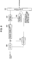
- FIG. 8 is a block diagram of a video decoding device in Exemplary Embodiment 3.
- FIG. 9 is a flowchart showing a PU header parsing operation.
- FIG. 10 is an explanatory diagram of a list indicative of information on a predetermined area and information on the maximum number of motion vectors allowed for an image block having the predetermined area in a picture parameter set.
- FIG. 11 is an explanatory diagram of a list indicative of information on a predetermined area and information on the number of motion vectors allowed for an image block having the predetermined area in a slice header.
- FIG. 12 is a block diagram of a video decoding device in Exemplary Embodiment 4.
- FIG. 13 is a flowchart showing an error detection operation.
- FIG. 14 is a block diagram showing a configuration example of an information processing system capable of implementing the functions of a video encoding device and a video decoding device according to the present invention.
- FIG. 15 is a block diagram showing a main part of a video encoding device according to the present invention.
- FIG. 16 is a block diagram showing a main part of a video decoding device according to the present invention.
- FIG. 17 is a block diagram of a typical video encoding device.
- FIG. 18 is an explanatory diagram showing an example of block division.
- FIG. 19 is an explanatory diagram for describing intra prediction of Intra_4 ⁇ 4 and Intra_8 ⁇ 8.
- FIG. 20 is an explanatory diagram for describing intra prediction of Intra_16 ⁇ 16.
- FIG. 21 is an explanatory diagram showing an example of inter prediction.
- FIG. 22 is an explanatory diagram showing interpolation processing for luminance signals in motion-compensated prediction.
- FIG. 23 is a block diagram of a typical video decoding device.
- FIG. 24 is an explanatory diagram for describing a CTB.
- FIG. 25 is an explanatory diagram for describing a PU.
- FIG. 26 is an explanatory diagram for describing decimal pixel positions.
- FIG. 27 is an explanatory diagram for describing a decimal pixel generation method using a twelve-tap filter in the TMuC scheme.
- FIG. 28 is an explanatory diagram for describing a memory access range when a decimal pixel is generated using a twelve-tap filter in the TMuC scheme.
- the present invention restricts inter-PU partitions of a CU to be encoded and an inter prediction direction based on the number of motion vectors of an encoded image block contained in an image block having a predetermined area to solve the problems.
- inter-PU partition type candidates and inter prediction direction candidates are respectively restricted based on the number of motion vectors of an encoded image block contained in an image block having a predetermined area to solve the problems.
- transmission of an inter-PU partition type syntax in a PU header is restricted to solve the problems.
- the ratio of the number of bits of the inter-PU partition type syntax included in a bitstream can be kept low to suppress the memory bandwidth while improving the quality of compressed video.
- the predetermined area means one LCU or successive two or more LCUs.
- Exemplary Embodiment 1 shows a video encoding device including: encoding control means for controlling an inter-PU partition type and an inter prediction direction based on the maximum number of motion vectors allowed for an image block having a predetermined area (a predetermined region in the image) and the number of motion vectors of an encoded image block contained in the image block having the predetermined area; and means for embedding, in a bitstream, information on the predetermined area and information on the maximum number of motion vectors allowed for the image block having the predetermined area to signal, to a video decoding device, the information on the maximum number of motion vectors allowed for the image block having the predetermined area.
- the predetermined area is LCUs of successive numSucLcu (one or more LCUs)
- the maximum number of motion vectors allowed per predetermined area is maxNumMV
- the number of motion vectors contained in an encoded CU within the predetermined area is currNumMV.
- the video encoding device in the exemplary embodiment includes a transformer/quantizer 101 , an entropy encoder 102 , an inverse transformer/inverse quantizer 103 , a buffer 104 , a predictor 105 , a multiplexer 106 , and an encoding controller 107 , like the typical video encoding device shown in FIG. 17 .
- the video encoding device in the exemplary embodiment shown in FIG. 1 differs from the video encoding device shown in FIG. 17 in that numSucLcu and maxNumMV are supplied to the encoding controller 107 to control the inter-PU partition type and the inter prediction direction based on numSucLcu and maxNumMV. NumSucLcu and maxNumMV are also supplied to the multiplexer 106 to signal numSucLcu and maxNumMV to the video decoding device.
- the encoding controller 107 has the predictor 105 calculate a cost (Rate-Distortion cost: R-D cost) calculated from a coding distortion (the energy of an error image between an input signal and a reconstructed picture) and a generated bit count.
- the encoding controller 107 determines a CU splitting pattern in which the R-D cost is minimized (the splitting pattern determined by split_coding_unit_flag as shown in FIG. 24 ), and prediction parameters of each CU.
- the encoding controller 107 supplies determined split_coding_unit_flag and the prediction parameters of each CU to the predictor 105 and the entropy encoder 102 .
- the prediction parameters are information associated with prediction of a CU to be encoded, such as prediction mode (pred_mode), intra-PU partition type (intra_split_flag), intra prediction direction, inter-PU partition type (inter_partitioning_idc), and motion vector.
- prediction mode pred_mode
- intra-PU partition type intra_split_flag
- intra prediction direction intra prediction direction
- inter_partitioning_idc inter-PU partition type
- the encoding controller 107 in the exemplary embodiment controls the PU partition type based on numSucLcu and maxNumMV.
- the encoding controller 107 in the exemplary embodiment selects the optimum PU partition type as a prediction parameter from a total of ten types of intra prediction ⁇ 2N ⁇ 2N, N ⁇ N ⁇ and a full set of inter prediction.
- the encoding controller 107 selects the optimum PU partition type as a prediction parameter from a total of nine types of intra prediction ⁇ 2N ⁇ 2N, N ⁇ N ⁇ and inter prediction ⁇ 2N ⁇ 2N, 2N ⁇ N, N ⁇ 2N, 2N ⁇ nU, 2N ⁇ nD, nL ⁇ 2N, nR ⁇ 2N ⁇ .
- the encoding controller 107 selects the optimum PU partition type as a prediction parameter from a total of three types of intra prediction ⁇ 2N ⁇ 2N, N ⁇ N ⁇ and inter prediction ⁇ 2N ⁇ 2N ⁇ .
- maxNumMV ⁇ currNumMV ⁇ 1 the encoding controller 107 selects the optimum PU partition type as a prediction parameter from two types of intra prediction ⁇ 2N ⁇ 2N, N ⁇ N ⁇ .
- FIG. 2 is a flowchart showing the operation of the encoding controller 107 in the exemplary embodiment to determine prediction parameters for each CU.
- the encoding controller 107 determines PU partition candidates in step S 101 .
- the encoding controller 107 determines inter prediction direction candidates.
- the encoding controller 107 uses the PU partition type and inter prediction direction candidates determined in step S 101 and step S 102 to determine prediction parameters based on the R-D cost.
- the encoding controller 107 updates currNumMV based on the PU partition type and the inter prediction direction determined in step S 102 and step S 103 .
- FIG. 3 is a flowchart showing an operation of determining the PU partition type candidates in step S 101 of FIG. 2 .
- the encoding controller 107 sets PU partition type candidates in step S 202 to a total of ten types of intra prediction ⁇ 2N ⁇ 2N, N ⁇ N ⁇ and a full set of inter prediction.
- the encoding controller 107 sets PU partition type candidates in step S 204 to a total of nine types of intra prediction ⁇ 2N ⁇ 2N, N ⁇ N ⁇ and inter prediction ⁇ 2N ⁇ 2N, 2N ⁇ N, N ⁇ 2N, 2N ⁇ nU, 2N ⁇ nD, nL ⁇ 2N, nR ⁇ 2N ⁇ .
- the encoding controller 107 sets PU partition type candidates in step S 206 to a total of three types of intra prediction ⁇ 2N ⁇ 2N, N ⁇ N ⁇ and inter prediction ⁇ 2N ⁇ 2N ⁇ .
- the encoding controller 107 sets PU partition type candidates to two types of intra prediction ⁇ 2N ⁇ 2N, N ⁇ N ⁇ .
- FIG. 4 is a flowchart showing an operation of determining the inter prediction direction candidates in step S 102 of FIG. 2 .
- step S 302 the encoding controller 107 sets the variable i representing the PU partition index to 1.
- the encoding controller 107 sets, in S 306 , the inter prediction direction candidates for partition i to ⁇ forward, backward ⁇ .
- step S 308 When i is equal to m in step S 308 , the process is ended.
- the predictor 105 selects a prediction signal corresponding to the prediction parameters of each CU determined by the encoding controller 107 .
- the prediction signal supplied from the predictor 105 is subtracted from input video of each CU in a shape determined by the encoding controller 107 to generate a prediction error image, and the prediction error image is input to the transformer/quantizer 101 .
- the transformer/quantizer 101 frequency-transforms the prediction error image to obtain a frequency transform coefficient.
- the transformer/quantizer 101 further quantizes the frequency transform coefficient with a predetermined quantization step width Qs to obtain a transform quantization value.
- the entropy encoder 102 entropy-encodes split_coding_unit_flag (see FIG. 24 ) supplied from the encoding controller 107 , the prediction parameters, and the transform quantization value supplied from the transformer/quantizer 101 .
- the inverse transformer/inverse quantizer 103 inverse-quantizes the transform quantization value with the predetermined quantization step width Qs.
- the inverse transformer/inverse quantizer 103 further performs inverse frequency transform of the frequency transform coefficient obtained by the inverse quantization.
- the prediction signal is added to the reconstructed prediction error image obtained by the inverse frequency transform, and the result is supplied to the buffer 104 .
- the multiplexer 106 multiplexes and outputs the information on the predetermined area, the information on the number of motion vectors allowed per predetermined area, and output data of the entropy encoder 103 .
- the multiplexer 106 multiplexes num_successive_largest_coding_unit (the value of numSucLcu in the exemplary embodiment) and max_num_motion_vector syntax (the value of maxNumMV in the exemplary embodiment) as listed in FIG. 5 .
- the video encoding device Based on the operation mentioned above, the video encoding device according to this invention generates a bitstream.
- the video encoding device in the exemplary embodiment includes the encoding control means for controlling the inter-PU partition type and inter prediction direction of a CU to be encoded based on the maximum number of motion vectors allowed for an image block having a predetermined area and the number of motion vectors of an encoded image block contained in the image block having the above predetermined area so that motion vectors greater in number than the maximum number of motion vectors allowed for the image block having the predetermined area will not be used within the predetermined area.
- the video encoding device sets, in a predetermined inter-PU partition type, and entropy-encodes an inter-PU partition type syntax in a PU header layer of the CU to be encoded.
- the memory bandwidth is reduced by preventing motion vectors greater in number than the maximum number of motion vectors from being used within the predetermined area. Further, since the number of inter-PU partition type syntaxes to be signaled is reduced by preventing the motion vectors greater in number than the maximum number of motion vectors from being used within the predetermined area, the percentage of the amount of code of a PU header in the bitstream is reduced, and hence the quality of video is improved.
- the video encoding device in the exemplary embodiment embeds, in the bitstream, the information on the predetermined area and the information on the maximum number of motion vectors allowed for the image block having the predetermined area.
- the interoperability of the video encoding device and the video decoding device can be enhanced.
- a video encoding device in Exemplary Embodiment 2 includes: encoding control means for controlling an inter-PU partition type and an inter prediction direction based on a predetermined area set from the outside and the maximum number of motion vectors allowed for an image block having the predetermined area to control entropy-encoding of an inter-PU partition type syntax based on the number of motion vectors of an encoded image block contained in the image block having the predetermined area mentioned above; and means for embedding, in a bitstream, information on the predetermined area, information on the maximum number of motion vectors allowed for the image block having the predetermined area, and information on the number of motion vectors allowed per predetermined area to signal, to a video decoding device, the information on the maximum number of motion vectors allowed for the image block having the predetermined area and the information on the number of motion vectors allowed per predetermined area.
- the predetermined area is LCUs of successive numSucLcu
- the maximum number of motion vectors allowed for the image block having the predetermined area is maxNumMV
- the number of motion vectors of an encoded CU contained in the image block within the predetermined area is currNumMV.
- the structure of the video encoding device in the exemplary embodiment is the same as the structure of the video encoding device in Exemplary Embodiment 1 shown in FIG. 1 .
- the video encoding device in this exemplary embodiment shown in FIG. 1 differs from the video encoding device shown in FIG. 17 in that numSucLcu and maxNumMV are supplied to the encoding controller 107 to control the inter-PU partition and the inter prediction direction based on numSucLcu and maxNumMV. NumSucLcu and maxNumMV are also supplied to the multiplexer 106 to signal numSucLcu and maxNumMV to the video decoding device.
- the encoding controller 107 has the predictor 105 calculate the R-D cost calculated from a coding distortion (the energy of an error image between an input signal and a reconstructed picture) and a generated bit count.
- the encoding controller 107 determines a CU splitting pattern in which the R-D cost is minimized (the splitting pattern determined by split_coding_unit_flag as shown in FIG. 24 ), and prediction parameters of each CU.
- the encoding controller 107 supplies the determined split_coding_unit_flag and prediction parameters of each CU to the predictor 105 and the entropy encoder 102 .
- the prediction parameters are information associated with prediction of a CU to be encoded, such as prediction mode (pred_mode), intra-PU partition type (intra_split_flag), intra prediction direction, inter-PU partition type (inter_partitioning_idc), and motion vector.
- prediction mode pred_mode
- intra-PU partition type intra_split_flag
- intra prediction direction intra prediction direction
- inter_partitioning_idc inter-PU partition type
- the encoding controller 107 in the exemplary embodiment determines PU partition type and inter prediction direction candidates.
- the encoding controller 107 uses the determined PU partition and inter prediction direction candidates to determine prediction parameters based on the R-D cost.
- the encoding controller 107 in the exemplary embodiment controls the entropy encoder 102 not to entropy-encode inter_partitioning_idc.
- the predictor 105 selects a prediction signal corresponding to the prediction parameters of each CU determined by the encoding controller 107 .
- the prediction signal supplied from the predictor 105 is subtracted from input video of each CU in a shape determined by the encoding controller 107 to generate a prediction error image, and the prediction error image is input to the transformer/quantizer 101 .
- the transformer/quantizer 101 frequency-transforms the prediction error image to obtain a frequency transform coefficient.
- the transformer/quantizer 101 further quantizes the frequency transform coefficient with a predetermined quantization step width Qs to obtain a transform quantization value.
- the entropy encoder 102 entropy-encodes split_coding_unit_flag (see FIG. 24 ) supplied from the encoding controller 107 , the prediction parameters, and the transform quantization value supplied from the transformer/quantizer 101 .
- the inverse transformer/inverse quantizer 103 inverse-quantizes the transform quantization value with the predetermined quantization step width Qs.
- the inverse transformer/inverse quantizer 103 further performs inverse frequency transform of the frequency transform coefficient obtained by the inverse quantization.
- the prediction signal is added to the reconstructed prediction error image obtained by the inverse frequency transform, and the result is supplied to the buffer 104 .
- the multiplexer 106 multiplexes and outputs the information on the predetermined area, the information on the number of motion vectors allowed per predetermined area, and output data of the entropy encoder 102 .
- the multiplexer 106 multiplexes num_successive_largest_coding_unit (the value of numSucLcu in the exemplary embodiment) and max_num_motion_vector syntax (the value of maxNumMV in the exemplary embodiment) as listed in FIG. 5 .
- the video encoding device of this invention Based on the operation described above, the video encoding device of this invention generates a bitstream.
- the entropy encoder 102 entropy-encodes split_coding_unit_flag in step S 401 .
- the entropy encoder 102 further entropy-encodes the prediction mode in step S 402 , i.e., the entropy encoder 102 entropy-encodes pred_mode syntax.
- the encoding controller 107 controls the entropy encoder 102 to skip entropy-encoding of inter_partitioning_idc syntax.
- the encoding controller 107 controls the entropy encoder 102 to entropy-encode, in step S 405 , PU partition type information on the CU to be encoded.
- the above-mentioned pred_mode syntax and inter_partitioning_idc syntax are signaled as represented in a list shown in FIG. 7 .
- the video encoding device in the exemplary embodiment includes the encoding control means for controlling an inter-PU partition type and an inter prediction direction based on the number of motion vectors (the maximum number of motion vectors ⁇ 1 in the exemplary embodiment) allowed per predetermined area based on the maximum number of motion vectors allowed for an image block having the predetermined area. Since the video encoding device does not transmit unnecessary inter-PU partition type information, the ratio of the number of bits of the inter-PU partition type included in a bitstream can be kept low to reduce the memory bandwidth while maintaining the quality of compressed video.
- the video encoding device in the exemplary embodiment includes the means for embedding, in a bitstream, information on the predetermined area set from the outside, the maximum number of motion vectors allowed for the image block having the predetermined area, and the number of motion vectors allowed per predetermined area so that an inter-PU partition type syntax can be parsed from the bitstream.
- the interoperability of the video encoding device and the video decoding device can be enhanced.
- the video encoding device in the exemplary embodiment performs control not to entropy-encode an inter-PU partition type syntax in a PU header layer of the CU to be encoded in order to reduce the number of inter-PU partition type syntaxes to be signaled, or performs control to signal the inter-PU partition type syntax only when the number of motion vectors is less than the value obtained by subtracting one from the maximum number of motion vectors. Since the reduction in the number of inter-PU partition type syntaxes to be signaled reduces the percentage of the amount of code of a PU header in the bitstream, the quality of video is further improved.
- a video decoding device in Exemplary Embodiment 3 decodes a bitstream generated by the video encoding device in Exemplary Embodiment 2.
- the video decoding device in this exemplary embodiment includes: means for de-multiplexing information on a predetermined area and information on the number of motion vectors allowed for an image block having the predetermined area that are multiplexed into a bitstream; and parsing means for parsing an inter-PU partition type from the bitstream based on the number of motion vectors of an encoded image block contained in the image block having the predetermined area.
- the video decoding device in the exemplary embodiment includes a de-multiplexer 201 , an entropy decoder 202 , an inverse transformer/inverse quantizer 203 , a predictor 204 , a buffer 205 , and a decoding controller 206 .
- the de-multiplexer 201 de-multiplexes an input bitstream and extracts information on the predetermined area, information on the number of motion vectors allowed for the image block having the predetermined area, and an entropy-encoded video bitstream.
- the de-multiplexer 201 de-multiplexes num_successive_largest_coding_unit syntax and max_num_motion_vector syntax in sequence parameters as listed in FIG. 5 .
- the de-multiplexer 201 further supplies the information on the predetermined area and the maximum number of motion vectors allowed for the image block having the predetermined area to the decoding controller 206 .
- the entropy decoder 202 entropy-decodes the video bitstream.
- the entropy decoder 202 supplies an entropy-decoded transform quantization value to the inverse transformer/inverse quantizer 203 .
- the entropy decoder 202 supplies entropy-decoded split_coding_unit_flag and prediction parameters to the decoding controller 206 .
- the decoding controller 206 in the exemplary embodiment controls the entropy decoder 202 to skip entropy-decoding of the inter-PU partition type syntax of the CU to be decoded.
- the de-multiplexer 201 further sets the inter-PU partition type of the CU to be decoded to 2N ⁇ 2N.
- currNumMV is updated based on an inter prediction direction of each partition to be decoded following the inter-PU partition type.
- the inverse transformer/inverse quantizer 203 inverse-quantizes transform quantization values of luminance and color difference with a predetermined quantization step width.
- the inverse transformer/inverse quantizer 203 further performs inverse frequency transform of a frequency transform coefficient obtained by the inverse quantization.
- the predictor 204 After the inverse frequency transform, the predictor 204 generates a prediction signal using an image of a reconstructed picture stored in the buffer 205 based on the prediction parameters supplied from the decoding controller 206 .
- the prediction signal supplied from the predictor 204 is added to a reconstructed prediction error image obtained by the inverse frequency transform performed by the inverse transformer/inverse quantizer 203 , and the result is supplied to the buffer 205 as a reconstructed picture.
- the reconstructed picture stored in the buffer 205 is then output as a decoded image.
- the video decoding device in the exemplary embodiment Based on the operation described above, the video decoding device in the exemplary embodiment generates a decoded image.
- the entropy decoder 202 entropy-decodes split_coding_unit_flag to decide the CU size in step S 501 .
- step S 502 the entropy decoder 202 entropy-decodes the prediction mode.
- the entropy decoder 202 entropy-decodes pred_mode syntax.
- the decoding controller 206 controls the entropy decoder 202 in step S 506 to entropy-decode the PU partition type of the CU to be decoded and to set the PU partition type of the CU to a PU partition type obtained as a result of the entropy-decoding.
- the video encoding device in Exemplary Embodiment 2 can multiplex, into a picture parameter set or a slice header, the information on the predetermined area (num_successive_largest_coding_unit) and the information on the number of motion vectors (max_num_motion_vector) allowed per predetermined area used in Exemplary Embodiment 1 as listed in FIG. 10 or FIG. 11 .
- FIG. 10 is an explanatory diagram of a list indicative of information on the predetermined area and information on the maximum number of motion vectors allowed for an image block having the predetermined area in a picture parameter set.
- FIG. 11 is an explanatory diagram of a list indicative of information on the predetermined area and information on the number of motion vectors allowed for the image block having the predetermined area in a slice header.
- the video decoding device of the above invention can de-multiplex num_successive_largest_coding_unit syntax and max_num_motion_vector syntax from the picture parameter set or the slice header.
- the video decoding device in the exemplary embodiment includes decoding control means for controlling an inter-PU partition type of a CU to be decoded and an inter prediction direction based on the maximum number of motion vectors allowed for an image block having a predetermined area and the number of motion vectors of an encoded image block contained in the image block having the predetermined area mentioned above so that motion vectors greater in number than the maximum number of motion vectors allowed for the image block having the predetermined area will not be used within the predetermined area.
- a video decoding device in Exemplary Embodiment 4 decodes a bitstream generated by the video encoding device in Exemplary Embodiment 1.
- the video decoding device in this exemplary embodiment includes: means for de-multiplexing information on a predetermined area and information on the maximum number of motion vectors allowed for an image block having the predetermined area that are multiplexed into a bitstream; and error detection means for detecting an error in an access unit accessing the bitstream including a CU to be decoded, based on the number of motion vectors of an encoded image block contained in the image block having the predetermined area mentioned above.
- the access unit is the unit of storing coded data for one picture.
- the error means violation of restrictions based on the number of motion vectors allowed per predetermined area.
- the video decoding device in the exemplary embodiment includes a de-multiplexer 201 , an entropy decoder 202 , an inverse transformer/inverse quantizer 203 , a predictor 204 , a buffer 205 , and an error detector 207 .
- the de-multiplexer 201 operates the same way as the de-multiplexer 201 in Exemplary Embodiment 3 to de-multiplex an input bitstream and extract information on a predetermined area, information on the maximum number of motion vectors allowed for an image block having the predetermined area, and an entropy-encoded video bitstream.
- the de-multiplexer 201 de-multiplexes num_successive_largest_coding_unit syntax and max_num_motion_vector syntax in sequence parameters as listed in FIG. 5 .
- the de-multiplexer 201 further supplies the information on the predetermined area and the maximum number of motion vectors allowed for the image block having the predetermined area to the error detector 207 .
- the entropy decoder 202 entropy-decodes the video bitstream.
- the entropy decoder 202 supplies an entropy-decoded transform quantization value to the inverse transformer/inverse quantizer 203 .
- the entropy decoder 202 then supplies entropy-decoded split_coding_unit_flag and prediction parameters to the error detector 207 .
- the error detector 207 performs error detection on the prediction parameters supplied from the entropy decoder 202 based on the information on the predetermined area and the maximum number of motion vectors allowed for the image block having the predetermined area supplied from the de-multiplexer 201 , and supplies the result to the predictor 204 .
- the error detection operation will be described later.
- the error detector 207 also plays a role as the decoding controller 206 in Exemplary Embodiment 3.
- the inverse transformer/inverse quantizer 203 operates the same way as the inverse transformer/inverse quantizer 203 in Exemplary Embodiment 3.
- the predictor 204 generates a prediction signal using an image of a reconstructed picture stored in the buffer 205 based on the prediction parameters supplied from the error detector 207 .
- the buffer 205 operates the same way as the buffer 205 in Exemplary Embodiment 3.
- the video decoding device in the exemplary embodiment Based on the operation described above, the video decoding device in the exemplary embodiment generates a decoded image.
- step S 601 when the error detector 207 determines that the prediction mode of a PU of the CU to be decoded is intra, the process is ended.
- the error detector 207 sets m in step S 602 as the number of PU partitions of the CU to be decoded.
- step S 605 when the number of motion vectors (maxNumMV ⁇ currNumMV) available for the remaining inter-PUs is less than the remaining number of partitions (m ⁇ i), the error detector 207 determines in step S 606 that there is an error, and notifies the outside of the error. For example, the error detector 207 outputs the address of the CU in which the error has occurred.
- step S 607 When maxNumMV ⁇ currNumMV is greater than or equal to the remaining number of partitions (m ⁇ i), the procedure proceeds to step S 607 .
- i is equal to m in step S 607 , the process is ended.
- the error detector 207 detects the error in an access unit accessing the bitstream including the CU to be decoded.
- the video encoding devices and the video decoding devices of the above inventions control an inter-PU partition of a CU to be encoded, based on the maximum number of motion vectors allowed for an image block having a predetermined area, but similar control can be performed by using the maximum number of inter-PU partitions allowed for the image block having the predetermined area or the greatest amount of memory access allowed for the image block having the predetermined area.
- Each of the aforementioned exemplary embodiments can be implemented in hardware or in a computer program.
- An information processing system shown in FIG. 14 includes a processor 1001 , a program memory 1002 , a storage medium 1003 for storing video data, and a storage medium 1004 for storing a bitstream.
- the storage medium 1003 and the storage medium 1004 may be different storage media, or storage areas on the same storage medium.
- a magnetic medium such as a hard disk can be used as the storage medium.
- a program for carrying out the function of each block (except the buffer block) shown in each of FIG. 1 , FIG. 8 , and FIG. 12 is stored in the program memory 1002 .
- the processor 1001 performs processing according to the program stored in the program memory 1002 to carry out the functions of the video encoding device or the video decoding device shown in FIG. 1 , FIG. 8 , or FIG. 12 , respectively.
- FIG. 15 is a block diagram showing a main part of a video encoding device according to the present invention.
- the video encoding device according to the present invention is a video encoding device for encoding video using inter prediction, including encoding control means 11 (the encoding controller 107 shown in FIG. 1 as an example) for controlling an inter-PU partition type of a CU to be encoded, based on the maximum number (PA) of motion vectors allowed for an image block having a predetermined area and the number (PB) of motion vectors of an encoded image block contained in the image block having the predetermined area.
- PA maximum number
- PB number
- FIG. 16 is a block diagram showing a main part of a video decoding device according to the present invention.
- the video decoding device according to the present invention is a video decoding device for decoding video using inter prediction, including decoding control means 21 (the decoding controller 206 shown in FIG. 8 as an example) for controlling an inter-PU partition type of a CU to be decoded, based on the maximum number (PA) of motion vectors allowed for an image block having a predetermined area and the number (PB) of motion vectors of a decoded image block contained in the image block having the predetermined area.
- PA maximum number
- PB number
Applications Claiming Priority (3)
| Application Number | Priority Date | Filing Date | Title |
|---|---|---|---|
| JP2011004963 | 2011-01-13 | ||
| JP2011-004963 | 2011-01-13 | ||
| PCT/JP2012/000045 WO2012096146A1 (ja) | 2011-01-13 | 2012-01-05 | 映像符号化装置、映像復号装置、映像符号化方法、映像復号方法及びプログラム |
Related Parent Applications (1)
| Application Number | Title | Priority Date | Filing Date |
|---|---|---|---|
| PCT/JP2012/000045 A-371-Of-International WO2012096146A1 (ja) | 2011-01-13 | 2012-01-05 | 映像符号化装置、映像復号装置、映像符号化方法、映像復号方法及びプログラム |
Related Child Applications (1)
| Application Number | Title | Priority Date | Filing Date |
|---|---|---|---|
| US17/060,828 Continuation US11323720B2 (en) | 2011-01-13 | 2020-10-01 | Video encoding device, video decoding device, video encoding method, video decoding method, and program using inter prediction |
Publications (2)
| Publication Number | Publication Date |
|---|---|
| US20130322542A1 US20130322542A1 (en) | 2013-12-05 |
| US10841588B2 true US10841588B2 (en) | 2020-11-17 |
Family
ID=46507055
Family Applications (4)
| Application Number | Title | Priority Date | Filing Date |
|---|---|---|---|
| US13/977,756 Active 2034-02-12 US10841588B2 (en) | 2011-01-13 | 2012-01-05 | Video encoding device, video decoding device, video encoding method, video decoding method, and program using inter prediction |
| US17/060,828 Active US11323720B2 (en) | 2011-01-13 | 2020-10-01 | Video encoding device, video decoding device, video encoding method, video decoding method, and program using inter prediction |
| US17/685,579 Active US11647205B2 (en) | 2011-01-13 | 2022-03-03 | Video encoding device, video decoding device, video encoding method, video decoding method, and program using inter prediction |
| US17/685,543 Active US11665352B2 (en) | 2011-01-13 | 2022-03-03 | Video encoding device, video decoding device, video encoding method, video decoding method, and program using inter prediction |
Family Applications After (3)
| Application Number | Title | Priority Date | Filing Date |
|---|---|---|---|
| US17/060,828 Active US11323720B2 (en) | 2011-01-13 | 2020-10-01 | Video encoding device, video decoding device, video encoding method, video decoding method, and program using inter prediction |
| US17/685,579 Active US11647205B2 (en) | 2011-01-13 | 2022-03-03 | Video encoding device, video decoding device, video encoding method, video decoding method, and program using inter prediction |
| US17/685,543 Active US11665352B2 (en) | 2011-01-13 | 2022-03-03 | Video encoding device, video decoding device, video encoding method, video decoding method, and program using inter prediction |
Country Status (9)
| Country | Link |
|---|---|
| US (4) | US10841588B2 (pl) |
| EP (2) | EP2665273B1 (pl) |
| JP (4) | JP5974899B2 (pl) |
| KR (4) | KR101851326B1 (pl) |
| CN (4) | CN108055538B (pl) |
| BR (3) | BR122020018552B1 (pl) |
| ES (1) | ES2900775T3 (pl) |
| PL (1) | PL2665273T3 (pl) |
| WO (1) | WO2012096146A1 (pl) |
Families Citing this family (11)
| Publication number | Priority date | Publication date | Assignee | Title |
|---|---|---|---|---|
| CN108055538B (zh) * | 2011-01-13 | 2021-10-29 | 日本电气株式会社 | 视频编码设备以及视频编码方法 |
| US9762899B2 (en) * | 2011-10-04 | 2017-09-12 | Texas Instruments Incorporated | Virtual memory access bandwidth verification (VMBV) in video coding |
| JP6731574B2 (ja) * | 2014-03-06 | 2020-07-29 | パナソニックIpマネジメント株式会社 | 動画像符号化装置および動画像符号化方法 |
| JP2015173404A (ja) * | 2014-03-12 | 2015-10-01 | 富士通株式会社 | 動画像符号化装置、動画像符号化方法及び動画像符号化用コンピュータプログラム |
| WO2015163167A1 (ja) * | 2014-04-23 | 2015-10-29 | ソニー株式会社 | 画像処理装置及び画像処理方法 |
| US10390087B2 (en) | 2014-05-01 | 2019-08-20 | Qualcomm Incorporated | Hypothetical reference decoder parameters for partitioning schemes in video coding |
| CN104125469B (zh) * | 2014-07-10 | 2017-06-06 | 中山大学 | 一种用于hevc的快速编码方法 |
| WO2016153251A1 (ko) * | 2015-03-23 | 2016-09-29 | 엘지전자 주식회사 | 비디오 신호의 처리 방법 및 이를 위한 장치 |
| WO2017183751A1 (ko) * | 2016-04-22 | 2017-10-26 | 엘지전자(주) | 인터 예측 모드 기반 영상 처리 방법 및 이를 위한 장치 |
| CN109076220B (zh) * | 2016-05-10 | 2022-08-09 | 三星电子株式会社 | 用于对图像进行编码/解码的方法及其装置 |
| CN108924551B (zh) * | 2018-08-29 | 2022-01-07 | 腾讯科技(深圳)有限公司 | 视频图像编码模式的预测方法及相关设备 |
Citations (10)
| Publication number | Priority date | Publication date | Assignee | Title |
|---|---|---|---|---|
| US20050249290A1 (en) | 2004-05-07 | 2005-11-10 | Stephen Gordon | Method and system for dynamic selection of transform size in a video decoder based on signal content |
| JP2007060452A (ja) | 2005-08-26 | 2007-03-08 | Nippon Telegr & Teleph Corp <Ntt> | 動画像予測符号化方法、動画像予測符号化装置、動画像予測符号化プログラム及びそのプログラムを記録したコンピュータ読み取り可能な記録媒体 |
| US20070147503A1 (en) | 2005-12-27 | 2007-06-28 | Toshiyuki Ikeda | Selection of encoded data, setting of encoded data, creation of recoded data, and recoding method and device |
| WO2010039728A2 (en) | 2008-10-03 | 2010-04-08 | Qualcomm Incorporated | Video coding with large macroblocks |
| US20110002380A1 (en) * | 2008-03-10 | 2011-01-06 | Hua Yang | Method and apparatus for predictive frame selection supporting enhanced efficiency and subjective quality |
| WO2011019250A2 (en) | 2009-08-14 | 2011-02-17 | Samsung Electronics Co., Ltd. | Method and apparatus for encoding video, and method and apparatus for decoding video |
| US20110164677A1 (en) * | 2008-09-26 | 2011-07-07 | Dolby Laboratories Licensing Corporation | Complexity Allocation for Video and Image Coding Applications |
| WO2012017858A1 (ja) | 2010-08-03 | 2012-02-09 | ソニー株式会社 | 画像処理装置と画像処理方法 |
| US20120147961A1 (en) * | 2010-12-09 | 2012-06-14 | Qualcomm Incorporated | Use of motion vectors in evaluating geometric partitioning modes |
| US20130077691A1 (en) * | 2011-06-20 | 2013-03-28 | Qualcomm Incorporated | Parallelization friendly merge candidates for video coding |
Family Cites Families (12)
| Publication number | Priority date | Publication date | Assignee | Title |
|---|---|---|---|---|
| JP2002101416A (ja) * | 2000-09-25 | 2002-04-05 | Fujitsu Ltd | 画像制御装置 |
| JP2004179687A (ja) * | 2002-11-22 | 2004-06-24 | Toshiba Corp | 動画像符号化/復号化方法及び装置 |
| KR101366093B1 (ko) * | 2007-03-28 | 2014-02-21 | 삼성전자주식회사 | 영상의 부호화, 복호화 방법 및 장치 |
| KR20080107965A (ko) * | 2007-06-08 | 2008-12-11 | 삼성전자주식회사 | 객체 경계 기반 파티션을 이용한 영상의 부호화, 복호화방법 및 장치 |
| CN107105257B (zh) * | 2007-06-29 | 2020-08-28 | 威勒斯媒体国际有限公司 | 图像编码装置、图像编码方法、图像译码装置、图像译码方法 |
| EP2034742A3 (en) * | 2007-07-25 | 2009-10-14 | Hitachi Ltd. | Video coding method and device |
| CN101394580B (zh) | 2007-09-21 | 2012-01-25 | 电信科学技术研究院 | Eps承载管理的方法、装置、mme及通信系统 |
| EP2048886A1 (en) * | 2007-10-11 | 2009-04-15 | Panasonic Corporation | Coding of adaptive interpolation filter coefficients |
| CN101394560B (zh) * | 2008-06-30 | 2010-09-01 | 浙江大学 | 一种用于视频编码的混合流水线装置 |
| JP2011004963A (ja) | 2009-06-25 | 2011-01-13 | Universal Entertainment Corp | 不正を防止すると共にゲームの進行をディーラにナビゲートするゲーミングシステム |
| US9137544B2 (en) * | 2010-11-29 | 2015-09-15 | Mediatek Inc. | Method and apparatus for derivation of mv/mvp candidate for inter/skip/merge modes |
| CN108055538B (zh) * | 2011-01-13 | 2021-10-29 | 日本电气株式会社 | 视频编码设备以及视频编码方法 |
-
2012
- 2012-01-05 CN CN201810101737.0A patent/CN108055538B/zh active Active
- 2012-01-05 KR KR1020137016920A patent/KR101851326B1/ko active IP Right Grant
- 2012-01-05 WO PCT/JP2012/000045 patent/WO2012096146A1/ja active Application Filing
- 2012-01-05 PL PL12734382T patent/PL2665273T3/pl unknown
- 2012-01-05 CN CN201810103418.3A patent/CN108111847B/zh active Active
- 2012-01-05 KR KR1020187010850A patent/KR101935217B1/ko active IP Right Grant
- 2012-01-05 KR KR1020167022895A patent/KR101840579B1/ko active IP Right Grant
- 2012-01-05 EP EP12734382.0A patent/EP2665273B1/en active Active
- 2012-01-05 KR KR1020157022459A patent/KR101841334B1/ko active IP Right Grant
- 2012-01-05 BR BR122020018552-0A patent/BR122020018552B1/pt active IP Right Grant
- 2012-01-05 CN CN201280005384.5A patent/CN103314590B/zh active Active
- 2012-01-05 CN CN201810102760.1A patent/CN108093255B/zh active Active
- 2012-01-05 BR BR112013017802-7A patent/BR112013017802B1/pt active IP Right Grant
- 2012-01-05 US US13/977,756 patent/US10841588B2/en active Active
- 2012-01-05 EP EP21197304.5A patent/EP3965418A1/en active Pending
- 2012-01-05 BR BR122020018553-8A patent/BR122020018553B1/pt active IP Right Grant
- 2012-01-05 JP JP2012552666A patent/JP5974899B2/ja active Active
- 2012-01-05 ES ES12734382T patent/ES2900775T3/es active Active
-
2016
- 2016-07-15 JP JP2016140172A patent/JP6233465B2/ja active Active
-
2017
- 2017-10-23 JP JP2017204300A patent/JP6432662B2/ja active Active
- 2017-10-23 JP JP2017204299A patent/JP6432661B2/ja active Active
-
2020
- 2020-10-01 US US17/060,828 patent/US11323720B2/en active Active
-
2022
- 2022-03-03 US US17/685,579 patent/US11647205B2/en active Active
- 2022-03-03 US US17/685,543 patent/US11665352B2/en active Active
Patent Citations (11)
| Publication number | Priority date | Publication date | Assignee | Title |
|---|---|---|---|---|
| US20050249290A1 (en) | 2004-05-07 | 2005-11-10 | Stephen Gordon | Method and system for dynamic selection of transform size in a video decoder based on signal content |
| JP2007060452A (ja) | 2005-08-26 | 2007-03-08 | Nippon Telegr & Teleph Corp <Ntt> | 動画像予測符号化方法、動画像予測符号化装置、動画像予測符号化プログラム及びそのプログラムを記録したコンピュータ読み取り可能な記録媒体 |
| US20070147503A1 (en) | 2005-12-27 | 2007-06-28 | Toshiyuki Ikeda | Selection of encoded data, setting of encoded data, creation of recoded data, and recoding method and device |
| JP2007180776A (ja) | 2005-12-27 | 2007-07-12 | Nec Corp | 符号化データ選定、符号化データ設定、再符号化データ生成及び再符号化の方法及び装置 |
| US20110002380A1 (en) * | 2008-03-10 | 2011-01-06 | Hua Yang | Method and apparatus for predictive frame selection supporting enhanced efficiency and subjective quality |
| US20110164677A1 (en) * | 2008-09-26 | 2011-07-07 | Dolby Laboratories Licensing Corporation | Complexity Allocation for Video and Image Coding Applications |
| WO2010039728A2 (en) | 2008-10-03 | 2010-04-08 | Qualcomm Incorporated | Video coding with large macroblocks |
| WO2011019250A2 (en) | 2009-08-14 | 2011-02-17 | Samsung Electronics Co., Ltd. | Method and apparatus for encoding video, and method and apparatus for decoding video |
| WO2012017858A1 (ja) | 2010-08-03 | 2012-02-09 | ソニー株式会社 | 画像処理装置と画像処理方法 |
| US20120147961A1 (en) * | 2010-12-09 | 2012-06-14 | Qualcomm Incorporated | Use of motion vectors in evaluating geometric partitioning modes |
| US20130077691A1 (en) * | 2011-06-20 | 2013-03-28 | Qualcomm Incorporated | Parallelization friendly merge candidates for video coding |
Non-Patent Citations (19)
| Title |
|---|
| "Information technology—Coding of audio-visual objects—Part 10: Advanced Video Coding", International Standard, ISO/IEC 14496-10, May 15, 2009, pp. 1-118, Fifth Edition. |
| "Test Model Under Consideration", Joint Collaborative Team on Video Coding (JCT-VC) of ITU-T SG16 WP3 and ISO/IEC JTC1/SC29/WG11, 2nd Meeting: Geneva, CH, Jul. 21-28, 2010, Document: JCTVC-B205, pp. 1-152. |
| "Test Model Under Consideration", Joint Collaborative Team on Video Coding (JCT-VC) of ITU-T SG16 WP3 and ISO/IEC JTC1/SC29/WG11, 2nd Meeting: Geneva, CH, Jul. 21-28, 2010, Document: JCTVC-B205, pp. 1-33. |
| Chono, et al., "Description of video coding technology proposal by NEC", JCTVC-A104, JCT-VC Meeting, Apr. 15-23, 2010, Dresden, XP030007534, 30 pages. |
| Communication dated Dec. 15, 2015, from the Japanese Patent Office in counterpart application No. 2012-552666. |
| Communication dated Jan. 16, 2018, from Korean Intellectual Property Office in counterpart application No. 10-2013-7016920. |
| Communication dated Jan. 16, 2018, from Korean Intellectual Property Office in counterpart application No. 10-2015-7022459. |
| Communication dated Nov. 12, 2015 from the Intellectual Property Office of the P.R. China issued in corresponding application No. 201280005384.5. |
| Communication dated Sep. 6, 2016, issued by the Korean Intellectual Property Office in corresponding Korean Application No. 10-2016-7022895. |
| Davies, et al., "Samsung and BBC response to Call for Proposals on Video Compression Technology", JCT-VC Meeting, Apr. 15-23, 2010, Dresden, XP030007576, 36 pages. |
| Extended European Search Report, dated Jun. 12, 2014, issued by the European Patent Office, in counterpart Application No. 12734382.0. |
| Han, et al., "Improved Video Compression Efficiency Through Flexible Unit Representation and Corresponding Extension of Coding Tools", IEEE Transactions on Circuits and Systems for Video Technology, IEEE Service Center, Piscataway, NJ, US, vol. 20, No. 12, Dec. 2010, XP011329409, 12 pages. |
| K. CHONO (NEC), K. SENZAKI (NEC), H. AOKI (NEC), J. TAJIME (NEC), Y. SENDA (NEC): "Video coding technology proposal by NEC", 1. JCT-VC MEETING; 15-4-2010 - 23-4-2010; DRESDEN; (JOINTCOLLABORATIVE TEAM ON VIDEO CODING OF ISO/IEC JTC1/SC29/WG11 AND ITU-TSG.16 ); URL: HTTP://WFTP3.ITU.INT/AV-ARCH/JCTVC-SITE/, JCTVC-A104, 18 April 2010 (2010-04-18), XP030007534 |
| Ken McCann et al. "Samsung Response to the call for proposals on video compression technology" Apr. 2010; 42 pages total. |
| NAITO S , MATSUMURA A, KOIKE A: "Efficient coding scheme for super high definition video based on extending H.264 high profile", PROCEEDINGS OF SPIE, IEEE, US, vol. 6077, no. 067727, 18 January 2006 (2006-01-18), US, pages 1 - 8, XP002538136, ISBN: 978-1-62841-730-2 |
| Naito, et al., "Efficient coding scheme for super high definition video based on extending H.264 high profile", Proceedings of SPIE, International Society for Optical Engineering, US, vol. 6077, No. 67727, Jan. 18, 2006, XP002538136, 8 pages. |
| T. DAVIES (BBC): "Video coding technology proposal by BBC (and Samsung)", 1. JCT-VC MEETING; 15-4-2010 - 23-4-2010; DRESDEN; (JOINTCOLLABORATIVE TEAM ON VIDEO CODING OF ISO/IEC JTC1/SC29/WG11 AND ITU-TSG.16 ); URL: HTTP://WFTP3.ITU.INT/AV-ARCH/JCTVC-SITE/, JCTVC-A125, 16 April 2010 (2010-04-16), XP030007576 |
| WOO-JIN HAN ; JUNGHYE MIN ; IL-KOO KIM ; ELENA ALSHINA ; ALEXANDER ALSHIN ; TAMMY LEE ; JIANLE CHEN ; VADIM SEREGIN ; SUNIL LEE ; : "Improved Video Compression Efficiency Through Flexible Unit Representation and Corresponding Extension of Coding Tools", IEEE TRANSACTIONS ON CIRCUITS AND SYSTEMS FOR VIDEO TECHNOLOGY, INSTITUTE OF ELECTRICAL AND ELECTRONICS ENGINEERS, US, vol. 20, no. 12, 1 December 2010 (2010-12-01), US, pages 1709 - 1720, XP011329409, ISSN: 1051-8215, DOI: 10.1109/TCSVT.2010.2092612 |
| Yoshinori Suzuki., "Reduction of MC Memory Access using Adaptive MV Coding", The Institute of Electronics, Information and Communication Engineers, vol. 103, No. 513, Dec. 2003, pp. 35-40. |
Also Published As
Similar Documents
| Publication | Publication Date | Title |
|---|---|---|
| US11647205B2 (en) | Video encoding device, video decoding device, video encoding method, video decoding method, and program using inter prediction | |
| US11943449B2 (en) | Video decoding device, and video encoding method performing entropy-decoding process for inter prediction unit partition type syntax | |
| US20240163449A1 (en) | Video encoding device performing entropy-encoding process for inter prediction unit partition type syntax | |
| US20240163448A1 (en) | Video decoding device and video encoding device using inter prediction |
Legal Events
| Date | Code | Title | Description |
|---|---|---|---|
| AS | Assignment |
Owner name: NEC CORPORATION, JAPAN Free format text: ASSIGNMENT OF ASSIGNORS INTEREST;ASSIGNORS:SENZAKI, KENTA;SENDA, YUZO;CHONO, KEIICHI;AND OTHERS;SIGNING DATES FROM 20130626 TO 20130705;REEL/FRAME:031007/0310 |
|
| STCV | Information on status: appeal procedure |
Free format text: ON APPEAL -- AWAITING DECISION BY THE BOARD OF APPEALS |
|
| STCV | Information on status: appeal procedure |
Free format text: BOARD OF APPEALS DECISION RENDERED |
|
| STPP | Information on status: patent application and granting procedure in general |
Free format text: DOCKETED NEW CASE - READY FOR EXAMINATION |
|
| STPP | Information on status: patent application and granting procedure in general |
Free format text: NOTICE OF ALLOWANCE MAILED -- APPLICATION RECEIVED IN OFFICE OF PUBLICATIONS |
|
| STPP | Information on status: patent application and granting procedure in general |
Free format text: PUBLICATIONS -- ISSUE FEE PAYMENT RECEIVED |
|
| STCF | Information on status: patent grant |
Free format text: PATENTED CASE |