US10835352B2 - Intraoral scanner and computing system for capturing images and generating three-dimensional models - Google Patents
Intraoral scanner and computing system for capturing images and generating three-dimensional models Download PDFInfo
- Publication number
- US10835352B2 US10835352B2 US15/925,093 US201815925093A US10835352B2 US 10835352 B2 US10835352 B2 US 10835352B2 US 201815925093 A US201815925093 A US 201815925093A US 10835352 B2 US10835352 B2 US 10835352B2
- Authority
- US
- United States
- Prior art keywords
- mouthpiece
- intraoral scanner
- handle
- images
- pattern
- Prior art date
- Legal status (The legal status is an assumption and is not a legal conclusion. Google has not performed a legal analysis and makes no representation as to the accuracy of the status listed.)
- Active - Reinstated, expires
Links
Images


Classifications
-
- A—HUMAN NECESSITIES
- A61—MEDICAL OR VETERINARY SCIENCE; HYGIENE
- A61C—DENTISTRY; APPARATUS OR METHODS FOR ORAL OR DENTAL HYGIENE
- A61C9/00—Impression cups, i.e. impression trays; Impression methods
- A61C9/004—Means or methods for taking digitized impressions
- A61C9/0046—Data acquisition means or methods
- A61C9/0053—Optical means or methods, e.g. scanning the teeth by a laser or light beam
- A61C9/006—Optical means or methods, e.g. scanning the teeth by a laser or light beam projecting one or more stripes or patterns on the teeth
-
- A—HUMAN NECESSITIES
- A61—MEDICAL OR VETERINARY SCIENCE; HYGIENE
- A61B—DIAGNOSIS; SURGERY; IDENTIFICATION
- A61B1/00—Instruments for performing medical examinations of the interior of cavities or tubes of the body by visual or photographical inspection, e.g. endoscopes; Illuminating arrangements therefor
- A61B1/00002—Operational features of endoscopes
- A61B1/00004—Operational features of endoscopes characterised by electronic signal processing
- A61B1/00009—Operational features of endoscopes characterised by electronic signal processing of image signals during a use of endoscope
-
- A—HUMAN NECESSITIES
- A61—MEDICAL OR VETERINARY SCIENCE; HYGIENE
- A61B—DIAGNOSIS; SURGERY; IDENTIFICATION
- A61B1/00—Instruments for performing medical examinations of the interior of cavities or tubes of the body by visual or photographical inspection, e.g. endoscopes; Illuminating arrangements therefor
- A61B1/00163—Optical arrangements
- A61B1/00193—Optical arrangements adapted for stereoscopic vision
-
- A—HUMAN NECESSITIES
- A61—MEDICAL OR VETERINARY SCIENCE; HYGIENE
- A61B—DIAGNOSIS; SURGERY; IDENTIFICATION
- A61B1/00—Instruments for performing medical examinations of the interior of cavities or tubes of the body by visual or photographical inspection, e.g. endoscopes; Illuminating arrangements therefor
- A61B1/00163—Optical arrangements
- A61B1/00194—Optical arrangements adapted for three-dimensional imaging
-
- A—HUMAN NECESSITIES
- A61—MEDICAL OR VETERINARY SCIENCE; HYGIENE
- A61B—DIAGNOSIS; SURGERY; IDENTIFICATION
- A61B1/00—Instruments for performing medical examinations of the interior of cavities or tubes of the body by visual or photographical inspection, e.g. endoscopes; Illuminating arrangements therefor
- A61B1/04—Instruments for performing medical examinations of the interior of cavities or tubes of the body by visual or photographical inspection, e.g. endoscopes; Illuminating arrangements therefor combined with photographic or television appliances
- A61B1/045—Control thereof
-
- A—HUMAN NECESSITIES
- A61—MEDICAL OR VETERINARY SCIENCE; HYGIENE
- A61B—DIAGNOSIS; SURGERY; IDENTIFICATION
- A61B1/00—Instruments for performing medical examinations of the interior of cavities or tubes of the body by visual or photographical inspection, e.g. endoscopes; Illuminating arrangements therefor
- A61B1/06—Instruments for performing medical examinations of the interior of cavities or tubes of the body by visual or photographical inspection, e.g. endoscopes; Illuminating arrangements therefor with illuminating arrangements
- A61B1/0605—Instruments for performing medical examinations of the interior of cavities or tubes of the body by visual or photographical inspection, e.g. endoscopes; Illuminating arrangements therefor with illuminating arrangements for spatially modulated illumination
-
- A—HUMAN NECESSITIES
- A61—MEDICAL OR VETERINARY SCIENCE; HYGIENE
- A61B—DIAGNOSIS; SURGERY; IDENTIFICATION
- A61B1/00—Instruments for performing medical examinations of the interior of cavities or tubes of the body by visual or photographical inspection, e.g. endoscopes; Illuminating arrangements therefor
- A61B1/24—Instruments for performing medical examinations of the interior of cavities or tubes of the body by visual or photographical inspection, e.g. endoscopes; Illuminating arrangements therefor for the mouth, i.e. stomatoscopes, e.g. with tongue depressors; Instruments for opening or keeping open the mouth
Definitions
- the present invention relates to intraoral scanning and, more particularly, to an improved intraoral scanner and computing system for capturing and producing higher quality three-dimensional imaging.
- Intraoral cameras and scanners are used by dentists or doctors to take images of the inside of a patients' mouth.
- Current scanners commonly operate by projecting structured light such as fringes or grid patterns, collecting and analyzing imagery of the projected patterns to be measured once they are modulated by the surface of the mouth.
- structured light such as fringes or grid patterns
- One factor limiting performance arises from the wide diversity of the materials being scanned within the mouth. Each material has unique optical properties and thereby reflects and scatters light differently.
- standard imaging techniques may lead to images with low quality such as poor contrast, low luminosity or image saturation. This could lead to incomplete or inaccurate measurements.
- current intraoral scanners include a mouth-piece that either cannot rotate with respect to the hand-piece or cannot rotate continuously.
- it is typically limited to 180-degree increments. This makes operation of the scanner less convenient to the operator and less comfortable to the patient.
- this limitation in motion could prevent the scanner mouth-piece from accessing hard-to-reach areas in the mouth cavity, hence reducing the quality of the 3D measurements performed.
- an intraoral scanner includes a handle, a mouthpiece extending from the handle, a structured light projector projecting a light pattern from the mouthpiece, and a stereo camera capturing images through the mouthpiece.
- the intraoral scanner further includes a flood illuminator projecting light from the mouthpiece.
- the handle includes a mounting dock and the mouthpiece includes a mounting receiver releasably coupled to the mounting dock.
- the mouthpiece may be rotatable relative to the handle about the mounting dock along a longitudinal axis of the intraoral scanner.
- the handle includes a locking pin spring biased to protrude radially from the mounting dock and a button operable to urge the locking pin inward against the bias of the spring.
- a plurality of pin slots may be formed circumferentially along an inner surface of the mounting receiver.
- the mounting receiver includes a first magnetic material and the mounting dock includes a second magnet material attracted to the first magnetic material.
- the light pattern is spatial modulation and/or temporal modulation.
- the spatial modulation may be a fringe pattern, a grid pattern, a random pattern, or a combination thereof.
- the capturing of images is at a video frame rate and is synchronized with the flood illuminator and the structured light projector.
- a system of capturing and processing image data includes an intraoral scanner having a structured light projector and a stereo camera, and a computing system operable to receive data from the intraoral scanner.
- the computing system includes a processor and a memory.
- the processor receives image data from the intraoral scanner, the image data including a plurality of images of a scene having a plurality of different materials.
- the processor identifies, within the plurality of images, an optimal image of each of the plurality of different materials.
- the processor further generates a high dynamic range image of the scene by combining the optimal images of each of the plurality of different materials.
- the scene is an inside of a mouth of a patient.
- the high dynamic range image includes an overlaid pattern projected by the structured light projector and captured by the stereo camera.
- the processor determines three-dimensional measurements of the scene using the overlaid pattern of the high dynamic range image.
- the processor further generates a digital three-dimensional model of the scene using the three-dimensional measurement.
- the intraoral scanner further includes a flood illuminator, a handle, and a mouthpiece extending from the handle.
- the flood illuminator projects light from the mouthpiece
- the structured light projector projects a light pattern from the mouthpiece
- the stereo camera captures images from the mouthpiece.
- a method of capturing and processing image data from within a patient's mouth includes the steps of: illuminating a plurality of materials within a patient's mouth with a structured light projector; capturing a plurality of images of the plurality of materials with a stereo camera; identifying, within the plurality of images, an optimal image of each of the plurality of different materials; and generating, by a computing system, a high dynamic range image of an inside of the patient's mouth by combining the optimal images of each of the plurality of different materials.
- the high dynamic range image includes an overlaid pattern projected by the structured light projector and captured by the stereo camera.
- the method further includes the steps of: determining three-dimensional measurements of the inside of the patient's mouth using the overlaid pattern of the high dynamic range image; and generating, by the computing system, a digital three-dimensional model of the inside of the patient's mouth using the three-dimensional measurements.
- the method further includes the step of illuminating the plurality of materials within the patient's mouth with a flood illuminator. In some embodiments, the steps of illuminating a plurality of materials within the patient's mouth with the flood illuminator and the structured light projector and capturing the plurality of images of the plurality of materials with a stereo camera are performed simultaneously using an intraoral scanner.
- FIG. 1 is a perspective view of an embodiment of an intraoral scanner supported by a support base of the present invention
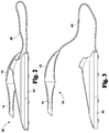
- FIG. 2 is a side view of an embodiment of an intraoral scanner supported by a support base of the present invention
- FIG. 3 is an exploded view of an embodiment of an intraoral scanner and a support base of the present invention
- FIG. 4 a is a detail cross sectional view of an embodiment of an intraoral scanner of the present invention.
- FIG. 4 b is a detail exploded view of an embodiment of an intraoral scanner of the present invention.
- FIG. 5 is a detail exploded view of an embodiment of an intraoral scanner of the present invention.
- FIG. 6 is a perspective view of an embodiment of an intraoral scanner supported by a support base and connected to a computing system of the present invention
- FIG. 7 is a schematic view of an embodiment of the present invention.
- FIG. 8 is a schematic view of an embodiment of the present invention.
- FIG. 9 is a flow chart of an embodiment of voxel hashing of the present invention.
- FIG. 10 is a flow chart of an embodiment of voxel hashing of the present invention.
- an embodiment of the present invention provides an intraoral scanner used in the field of digital dentistry for capturing 3D and color information of the surface of teeth, gum, dental impressions, stone models and the like.
- the disclosed invention also employs a hardware setup combining two 3D scanning techniques: projection of structured light and multiple-camera imaging.
- the introduction of a new method (voxel hashing) of encoding mutable 3D information in a scalar field yields a 3D volume with an effective resolution multiple-times greater than that achievable with traditional methods.
- the present invention creates 3D reconstruction models with enhanced accuracy.
- the present invention includes an intraoral scanner 10 .
- the intraoral scanner 10 includes a handle 12 and a mouthpiece 14 extending from the handle 12 .
- the intraoral scanner 10 further includes a flood illuminator 16 projecting light from the mouthpiece 14 and a structured light projector 18 projecting a light pattern from the mouthpiece 14 .
- a stereo camera 19 captures images through the mouthpiece 14 .
- the present invention may include a support base 44 .
- the support base 44 is configured to releasably secure the intraoral scanner 10 when the intraoral scanner 10 is not in use.
- the support base 44 may supply wired or wireless power to the intraoral scanner 10 .
- the support base 44 may include a battery, which supplies power to the intraoral scanner 10 .
- the support base 44 includes a power cord connected to an outlet or another power source port, such as a USB port.
- An electrical wiring 46 runs from the support base 44 to the intraoral scanner 10 , thereby providing power to the intraoral scanner 10 .
- the intraoral scanner 10 may further include a controller unit 29 disposed within the handle.
- the controller unit 29 may synchronize the flood illuminator 16 , the structure light projector 18 , and the stereo camera 19 to activate at the same time.
- the controller unit 29 may further interact with and send image data to a computing system 100 .
- the handle 12 may further include a mounting dock 20 having an inner sidewall defining a channel 23 in which light from the flood illuminator 16 and the structured light projector 18 is projected through.
- the mouthpiece 14 includes a mounting receiver 22 formed at a proximal end.
- the mounting receiver 22 releasably couples to the mounting dock 20 .
- An outer surface of the mounting dock 20 has a shape that is defined by an inner surface of the mounting receiver 22 .
- the mounting dock 20 may include a cylindrical or frustoconical shape, while an inner surface of the mounting receiver 22 defines the cylindrical or frustoconical shape.
- the mounting dock 20 may slide into and nest within the mounting receiver 22 .
- An inner surface of the mouthpiece 14 also defines a channel 25 aligning with the channel 23 of the mounting dock 20 .
- the channel 25 of the mouthpiece 14 ends at an opening 24 formed at a distal end of the mouthpiece 14 .
- the opening 24 may be substantially perpendicular to the channels 23 , 25 .
- an angled mirror 26 is disposed at the distal end of the mouthpiece 14 , within the channel 25 and above the opening 24 .
- the angled mirror 26 may be disposed at about 30 degrees up to about 60 degrees, such as about 45 degrees, relative to the opening 24 and the channels 23 , 25 .
- Light is projected from the flood illuminator 16 and the structured light projector 18 . The light travels through the aligned channels 23 , 25 and is reflected off of the angled mirror 26 , through the opening 24 and onto a target scene.
- Sensors of the stereo camera 19 capture images of the target scene from the reflection of the mirror 26 .
- the mouthpiece 14 may be rotatable relative to the handle 12 about a longitudinal axis 28 of the intraoral scanner.
- the handle 12 includes a locking pin 30 spring biased to protrude radially from the mounting dock 20 and a button 32 operable to urge the locking pin 30 inward against the bias of the spring 34 .
- a plurality of pin slots 36 are formed circumferentially along an inner surface of the mounting receiver 22 .
- the locking pin 30 protrudes into one of the slots 36 , fixing the mouthpiece 14 to the handle 12 .
- the pin slots 36 may be evenly spaced apart at 90-degree intervals, 45-degree intervals and the like. For example, four pin slots 36 may be evenly spaced apart 90-degrees away from one another.
- a user may scan a portion of the patient's mouth, remove the mouthpiece, press the button 32 to urge the locking pin 30 inward and out of a pin slot 36 , rotate the mouthpiece 14 relative to the handle 12 and release the button so that the locking pin 30 enters a different pin slot 36 .
- the user may place the mouthpiece 14 back into the patient's mouth and scan a different portion of the patient's mouth.
- the handle 12 connects to the mouthpiece 14 by magnetic materials.
- the mounting receiver 22 includes a first magnetic material 38 and the mounting dock 20 includes a second magnetic material 40 attracted to the first magnetic material 38 .
- the first and second magnetic materials 38 , 40 may include a combination of a magnet and a ferromagnet or a combination of two attracting magnets.
- the mouthpiece 14 rotates relative to the handle 12 about a longitudinal axis 28 continuously over a full 360-degree range. This facilitates user operation when accessing hard-to-reach areas in the mouth cavity and results in the collection of more data and in turn more accurate 3D measurements.
- the two light sources include the flood illuminator 16 and the structured light projector 18 .
- the two light sources may be white light sources or monochromatic sources, such as laser diodes.
- the light incident from both light sources is returned into the mouthpiece 14 after reflection and scattering by various objects in the mouth cavity such as teeth, gum, crowns and other dental restorations for example.
- the flood illuminator 16 is an illuminator unit dedicated to illuminating the mouth cavity in a uniform manner.
- the light beam generated by the flood illuminator is delivered to the area of interest in the mouth cavity by the mouthpiece 14 .
- the flood illuminator 16 allows the stereo camera 19 to capture accurate colors of the materials of the target scene.
- the structured light projector 18 projects a light pattern (structured light) onto the mouth cavity, through the mouthpiece 14 .
- the structure light projector 18 is used to project structured light onto the surface to be measured.
- the projected pattern can feature spatial modulation (such as fringes, grid or random patterns), temporal modulation, or a combination thereof.
- the projected light can be monochromatic or polychromatic.
- the stereo camera 19 of the present invention includes a first camera 19 a and a second camera 19 b synchronously capturing images of the illuminated mouth cavity.
- the stereo camera 19 is a system of two cameras 19 a , 19 b with overlapping field-of-views, each equipped with monochromatic or color image sensors. Image capture for both sensors is synchronized in order to mitigate the effect of system motion on the resulting 3D measurements.
- the cameras 19 a , 19 b may include charge coupled device (CCD) or complementary metal-oxide semiconductor (CMOS) sensors. Each sensor captures a stream of images of the mouth cavity. In each image of the stream, various materials may be present such as teeth, gum, or filling material, for example, with an overlaid light pattern from the structured light projector 18 .
- Synchronization of the illumination using the flood illuminator 16 , illumination using the structured light projector 18 and the image capture using the stereo camera 19 is performed by the intraoral scanner 10 .
- the capture of the stereo image pairs may occur at video frame rate and is synchronized and simultaneous with the structured light projector 18 and flood illuminator 16 .
- the present invention further includes a computing system 100 for processing, rendering, and exporting image data captured by the intraoral scanner 10 .
- the computing system 100 is at least the processor and the memory.
- the computing system 100 may execute on any suitable operating system such as IBM's zSeries/Operating System (z/OS), MS-DOS, PC-DOS, MAC-iOS, WINDOWS, UNIX, OpenVMS, ANDROID, an operating system based on LINUX, or any other appropriate operating system, including future operating systems.
- IBM's zSeries/Operating System z/OS
- MS-DOS MS-DOS
- PC-DOS PC-DOS
- MAC-iOS MAC-iOS
- WINDOWS UNIX
- OpenVMS OpenVMS
- ANDROID an operating system based on LINUX, or any other appropriate operating system, including future operating systems.
- the computing system 100 includes a processor, memory, a user interface, and a communication interface.
- the processor includes hardware for executing instructions, such as those making up a computer program.
- the memory includes main memory for storing instructions such as computer program(s) for the processor to execute, or data for processor to operate on.
- the memory may include an HDD, a floppy disk drive, flash memory, an optical disc, a magneto-optical disc, magnetic tape, a Universal Serial Bus (USB) drive, a solid-state drive (SSD), or a combination of two or more of these.
- the memory may include removable or non-removable (or fixed) media, where appropriate.
- the memory may be internal or external to the computing system 100 , where appropriate.
- the memory is non-volatile, solid-state memory.
- the user interface includes hardware, software, or both providing one or more interfaces for user communication with the computing system 100 .
- the user interface may include a keyboard, keypad, microphone, monitor, mouse, printer, scanner, speaker, still camera, stylus, tablet, touchscreen, trackball, video camera, another user interface or a combination of two or more of these.
- the communication interface includes hardware, software, or both providing one or more interfaces for communication (e.g., packet-based communication) between the computing system 100 , the intraoral scanner 10 and other computing systems or one or more networks.
- the intraoral scanner 10 may be directly hard wired to the computing system 100 , such as through a USB port or other cable connection interface and may transfer image data through the cable connection.
- the intraoral scanner 10 may be hard wired to the computing system 100 through the support base 44 .
- the intraoral scanner 10 may transfer image data using wireless communication.
- the computing system 100 and the intraoral scanner 10 may include a communication interface including a network interface controller (NIC) or network adapter for communicating with an Ethernet or other wire-based network or a wireless NIC (WNIC) or wireless adapter for communicating with a wireless network, such as a WI-FI network.
- NIC network interface controller
- WNIC wireless NIC
- This disclosure contemplates any suitable network and any suitable communication interface.
- the intraoral scanner 10 and the computing system 100 may communicate via an ad hoc network, a personal area network (PAN), a local area network (LAN), a wide area network (WAN), a metropolitan area network (MAN), or one or more portions of the Internet or a combination of two or more of these.
- PAN personal area network
- LAN local area network
- WAN wide area network
- MAN metropolitan area network
- the intraoral scanner 10 and the computing system 100 may communicate via a wireless PAN (WPAN) (e.g., a BLUETOOTH WPAN), a WI-FI network, a WI-MAX network, a cellular telephone network (e.g., a Global System for Mobile Communications (GSM) network), or other suitable wireless network or a combination of two or more of these.
- WPAN wireless PAN
- WI-FI wireless Fidelity
- WI-MAX Wireless Fidelity
- GSM Global System for Mobile Communications
- GSM Global System for Mobile Communications
- the intraoral scanner 10 and the computing system 100 may include any suitable communication interface for any of these networks, where appropriate.
- the computing system 100 receives image data from the intraoral scanner 10 .
- the image data includes a plurality of images of a scene having a plurality of different materials.
- the scene is an inside of a mouth of a patient and the plurality of different materials includes teeth, gums, crowns and other dental restorations.
- the processor performs data processing such as reconstructing a 3D model, data rendering, and exporting data to a format usable by the user.
- the high dynamic range (HDR) processing stage combines images of the scene that were captured for various exposures into a single HDR image.
- the processor identifies, within the plurality of images, an optimal image of each of the plurality of different materials and generates the HDR image of the scene by combining the optimal images of each of the plurality of different materials.
- the computer system 100 selects the optimal image based on the exposure for each of the materials visible in the frame.
- the exposure of the image can be controlled in two ways: by modifying the exposure time of the image capture or by modifying the intensity (luminance) of the illuminator or projector used.
- the exposure of the frame is selected so that image areas for one material exhibit good image quality (i.e. clear contrast and high luminosity). This means that areas with other materials visible in the frame could have lower quality (for example they could become over-exposed or under-exposed). Images of the same scene with various exposures are collected sequentially. This allows collecting high quality images for each material (area).
- the HDR image exhibits image quality that is higher than any of the original images captured due to varying exposures.
- the present invention allows for better visualization of details in the images, and especially when imaging various materials such as tooth, gum, filling, or stone/gypsum.
- the method also reduces image saturation (glint effect) encountered in the presence of wetness (saliva or blood) on the surface of the tooth or gum which is detrimental to the performance of intraoral systems.
- the HDR processing stage can be implemented as a digital image processor using a software approach (computer code) or a hardware approach [such as Field-Programmable Gate Arrays (FPGA's) or multi-processor units] or a combination of both.
- the HDR-enhanced image is then used for computation of the 3D measurements.
- the detection and identification of the projected pattern is facilitated by using the HDR-enhanced imagery.
- the HDR image includes the overlaid pattern projected by the structured light projector and captured by the stereo camera.
- the computing system 100 determines three-dimensional measurements of the scene using the overlaid pattern of the high dynamic range image and generates a digital three-dimensional model of the scene using the three-dimensional measurements. Using the combination of the stereo cameras 19 and the structured light projector 18 , the measurements are more accurate and complete. Another benefit of this method is that the remainder of the 3D measurement pipeline does not need to be altered for processing HDR-enhanced data instead of regular data.
- a method of capturing and processing image data from within a patient's mouth includes the following steps.
- An operator inserts the mouthpiece 14 into a patient's mouth.
- the operator presses a button 42 to turn on the flood illuminator 16 and the structured light projector 18 , thereby illuminating a plurality of materials within the patient's mouth.
- the button 42 simultaneously activates the stereo camera 19 which captures images of the plurality of materials inside of the patient's mouth.
- the digital images are saved on a memory.
- the operator may then remove the mouthpiece 14 from the patient's mouth and rotate the mouthpiece relative to the handle 12 .
- the operator then inserts the mouthpiece 14 back into the patient's mouth and presses the button 42 to capture and save additional digital images.
- the above steps may be repeated until the operator has captured a sufficient amount of digital images to reconstruct a target scene.
- the method further includes processing the above captured digital images.
- the image data is sent to the computing system 100 for processing, rendering, and exporting.
- An optimal image of each of the plurality of different materials is identified by the computing system 100 .
- a high dynamic range image of the target scene is generated by combining the optimal images of each of the plurality of different materials by the computing system 100 .
- the optimal images are selected based on the materials exposure quality.
- the computing system 100 selects the exposure for each image based on the materials visible in the frame.
- the method further includes rendering a three-dimensional image of the scene.
- the high dynamic range image includes the overlaid pattern projected by the structured light projector 18 and captured by the stereo camera 19 .
- the computer system 100 determines three-dimensional measurements of the inside of the patient's mouth using the overlaid pattern of the high dynamic range image.
- the computer system 100 generates a digital three-dimensional model of the inside of the patient's mouth using the three-dimensional measurements.
- aspects of the present invention include an improved system and method for 3D data processing, to include 3D data collection, storage and processing. With these improvements greater 3D resolution can be achieved, and faster 3D measurements can be made. In addition, the amount of memory required to represent the 3D scalar volume data is substantially reduced.
- 3D information is traditionally encoded in a scalar volume described by a truncated signed distance function (TSDF).
- TSDF truncated signed distance function
- the dimensions of this scalar volume are fixed and determined by the available memory of the device on which the information is stored, by way of non-limiting example, the device may include a graphics processing unit (GPU), a central processing unit (CPU), or a field-programmable gate array (FPGA).
- GPU graphics processing unit
- CPU central processing unit
- FPGA field-programmable gate array
- the memory block representing the scalar volume must be allocated at run-time and is static.
- the required memory increases with an inverse-cubic relationship to the voxel size. For example, doubling the resolution of the scalar volume (or halving the voxel size) requires eight-times more device memory, while tripling the resolution requires a 27-times more memory, and so on.
- voxels are instead allocated as needed when their weights/values are modified beyond a non-zero default.
- the method of the present invention uses a hash key to represent the spatial index of the voxel.
- This hash key is then stored in a two-dimensional hash table to correlate each allocated voxel's respective hash key to a memory block in a pre-allocated heap.
- the hash key itself stores at the very least the X, Y, and Z spatial indices of the voxel it represents. Additional information can also be encoded in the key, such as a culling/removal bit.
- the hash key may include three 13-bit keys describing each of the X, Y, and Z spatial indices of the voxel within the scalar volume and one 1-bit culling flag (indicating that the voxel is no longer used and should be removed).
- the 40-bit voxel hash key provides for a scalar volume with a maximum dimensionality of 2 13 ⁇ 2 13 ⁇ 2 13 voxels, or 8192 ⁇ 8192 ⁇ 8192 voxels.
- a combination of a two-dimensional hash table and a pre-allocated voxel heap are used.
- a mutable offset value (heap pointer) is used to keep track of the next block in the pre-allocated heap available for dynamic allocation.
- the hash table instantiated with 2 13 ⁇ 2 13 bucket nodes in size, representing each of a voxel's possible X, Y spatial indices within the scalar volume.
- Each of these bucket nodes represent the head of a singly-linked list of child nodes, with each child node containing data describing the next node in the singly-linked list (if there is a next node) and an offset in the pre-allocated voxel heap representing the node's respective voxel's data block.
- the X, Y, and Z spatial indices of the requested voxel is passed to a lookup-function.
- This lookup-function first checks the hash table to determine if the bucket node at the requested voxel's X, Y spatial index contains a data offset representing any voxel's data block.
- the lookup-function will traverse the list until the “next node” value of the child node(s) yields a null value, thus indicating the end of the singly-linked list.
- the child nodes' respective voxel data is checked for its hash key, from which its respective spatial Z index is extracted. If this spatial Z index matches the requested spatial Z index, then the data offset stored in that node (and thus the voxel data itself) is returned.
- the lookup-function then dynamically allocates a single voxel. This is done by first atomically incrementing the heap pointer while simultaneously taking old value prior to the increment. This offset value represents this newly allocated voxel's block of memory. This offset value is then stored in the next available child node (or bucket node if no child node exists at the X, Y spatial index), and the node is inserted into the list at the voxel's respective X, Y spatial index.
- the hashing approach of the present invention instead allows for only occupied voxels to be represented in memory.
- the effective resolution of the 3D volume may be greatly increased and the effective size of the voxel may be greatly reduced. In turn, this results in a much more accurate 3D reconstruction.
Landscapes
- Health & Medical Sciences (AREA)
- Life Sciences & Earth Sciences (AREA)
- Surgery (AREA)
- Physics & Mathematics (AREA)
- Veterinary Medicine (AREA)
- Public Health (AREA)
- Optics & Photonics (AREA)
- General Health & Medical Sciences (AREA)
- Animal Behavior & Ethology (AREA)
- Engineering & Computer Science (AREA)
- Medical Informatics (AREA)
- Biophysics (AREA)
- Biomedical Technology (AREA)
- Molecular Biology (AREA)
- Radiology & Medical Imaging (AREA)
- Pathology (AREA)
- Nuclear Medicine, Radiotherapy & Molecular Imaging (AREA)
- Heart & Thoracic Surgery (AREA)
- Dentistry (AREA)
- Oral & Maxillofacial Surgery (AREA)
- Epidemiology (AREA)
- Signal Processing (AREA)
- Dental Tools And Instruments Or Auxiliary Dental Instruments (AREA)
- Endoscopes (AREA)
Abstract
Description
Memory Address=X index+(Y index *X dim)+(Z index *Y dim *X dim)
Claims (16)
Priority Applications (3)
| Application Number | Priority Date | Filing Date | Title |
|---|---|---|---|
| US15/925,093 US10835352B2 (en) | 2018-03-19 | 2018-03-19 | Intraoral scanner and computing system for capturing images and generating three-dimensional models |
| US29/649,000 USD884175S1 (en) | 2018-03-19 | 2018-05-25 | Intraoral scanner |
| US16/949,815 US20210059793A1 (en) | 2018-03-19 | 2020-11-16 | Intraoral scanner and computing system for capturing images and generating three-dimensional models |
Applications Claiming Priority (1)
| Application Number | Priority Date | Filing Date | Title |
|---|---|---|---|
| US15/925,093 US10835352B2 (en) | 2018-03-19 | 2018-03-19 | Intraoral scanner and computing system for capturing images and generating three-dimensional models |
Related Child Applications (2)
| Application Number | Title | Priority Date | Filing Date |
|---|---|---|---|
| US29641236 Continuation-In-Part | 2018-03-19 | 2018-03-20 | |
| US16/949,815 Continuation US20210059793A1 (en) | 2018-03-19 | 2020-11-16 | Intraoral scanner and computing system for capturing images and generating three-dimensional models |
Publications (2)
| Publication Number | Publication Date |
|---|---|
| US20190282342A1 US20190282342A1 (en) | 2019-09-19 |
| US10835352B2 true US10835352B2 (en) | 2020-11-17 |
Family
ID=67903710
Family Applications (2)
| Application Number | Title | Priority Date | Filing Date |
|---|---|---|---|
| US15/925,093 Active - Reinstated 2038-11-18 US10835352B2 (en) | 2018-03-19 | 2018-03-19 | Intraoral scanner and computing system for capturing images and generating three-dimensional models |
| US16/949,815 Abandoned US20210059793A1 (en) | 2018-03-19 | 2020-11-16 | Intraoral scanner and computing system for capturing images and generating three-dimensional models |
Family Applications After (1)
| Application Number | Title | Priority Date | Filing Date |
|---|---|---|---|
| US16/949,815 Abandoned US20210059793A1 (en) | 2018-03-19 | 2020-11-16 | Intraoral scanner and computing system for capturing images and generating three-dimensional models |
Country Status (1)
| Country | Link |
|---|---|
| US (2) | US10835352B2 (en) |
Families Citing this family (11)
| Publication number | Priority date | Publication date | Assignee | Title |
|---|---|---|---|---|
| WO2019005056A1 (en) * | 2017-06-29 | 2019-01-03 | Carestream Dental Technology Topco Limited | Automatic intraoral 3d scanner using light sheet active triangulation |
| USD884175S1 (en) * | 2018-03-19 | 2020-05-12 | 3D Imaging And Stimulation Corp. Americas | Intraoral scanner |
| USD918209S1 (en) * | 2019-03-08 | 2021-05-04 | D4D Technologies, Llc | Handheld scanner tip |
| CN114078103A (en) * | 2020-08-21 | 2022-02-22 | 先临三维科技股份有限公司 | Method and system for reconstructing data and scanning equipment |
| JP7389484B2 (en) * | 2020-12-23 | 2023-11-30 | あしかメディ工業株式会社 | Cervical cancer examination device |
| EP4205695B1 (en) * | 2021-12-30 | 2025-02-19 | Medit Corp. | Intraoral scanning and imaging system |
| CN114831756B (en) * | 2022-05-02 | 2024-10-29 | 先临三维科技股份有限公司 | Intraoral scanning processing method, system, electronic device and medium |
| USD988513S1 (en) | 2022-08-19 | 2023-06-06 | Sprintray Inc. | Intraoral scanner |
| EP4591424A1 (en) * | 2022-09-21 | 2025-07-30 | 3Shape A/S | An intraoral scanning device with a supply assembly unit |
| JP1773373S (en) * | 2022-11-04 | 2024-06-18 | Scanner support | |
| US20250086877A1 (en) * | 2023-09-12 | 2025-03-13 | Qualcomm Incorporated | Content-adaptive 3d reconstruction |
Citations (66)
| Publication number | Priority date | Publication date | Assignee | Title |
|---|---|---|---|---|
| US5003166A (en) * | 1989-11-07 | 1991-03-26 | Massachusetts Institute Of Technology | Multidimensional range mapping with pattern projection and cross correlation |
| US5702249A (en) * | 1995-05-19 | 1997-12-30 | Cooper; David H. | Modular intra-oral imaging system video camera |
| US5771067A (en) * | 1992-09-11 | 1998-06-23 | Williams; Ronald R. | Dental video camera with an electrically adjustable iris |
| US5865725A (en) * | 1995-09-13 | 1999-02-02 | Moritex Corporation | Image capture instrument with side view angle |
| US6002424A (en) * | 1997-06-12 | 1999-12-14 | Schick Technologies, Inc. | Dental imaging system with white balance compensation |
| US6181369B1 (en) * | 1997-01-09 | 2001-01-30 | Matsushita Electric Industrial Co., Ltd. | Videoscope for dental or other use |
| US6276934B1 (en) * | 1998-02-19 | 2001-08-21 | Miratech Dental Imaging, Ltd. | Dental camera |
| US20010026315A1 (en) * | 2000-03-29 | 2001-10-04 | Matsushita Electric Industrial Co., Ltd. | Video scope |
| DE10105497A1 (en) | 2001-02-07 | 2002-08-08 | Rodenstock Praez Soptik Gmbh | Dental camera has lens head with LED illumination device, connected to camera handle |
| USD468429S1 (en) | 2001-03-26 | 2003-01-07 | Kaltenbach & Voight Gmbh | Intraoral camera |
| DE19619951C2 (en) | 1996-05-17 | 2003-02-06 | Regine Tuckermann | Optical measuring system of the dental apparatus with a miniaturized special endoscope camera, a micro laser probe and a mechanical probe needle for displaying and correcting the tooth topography, especially the occlusal surfaces, with a view to optimizing the bite design, as well as digitizing the measured values and transferring them to the CNC for the production of fillings and dentures |
| JP3414857B2 (en) | 1994-09-01 | 2003-06-09 | オーエスジー株式会社 | Dental tool rotary operating device and dental tool |
| US6606113B2 (en) * | 1995-05-24 | 2003-08-12 | Olympus Optical Co., Ltd. | Stereoscopic endocsope system and TV imaging system for endoscope |
| US20040117052A1 (en) * | 1999-03-29 | 2004-06-17 | Geng Z. Jason | Sanitary sleeve or tip for intra-oral three-dimensional camera |
| US20040166471A1 (en) | 2003-02-20 | 2004-08-26 | Polytec Gmbh | Method and device for optical measurement of a cast model of a tooth in restorative dentistry |
| US20050090749A1 (en) * | 1996-09-02 | 2005-04-28 | Rudger Rubbert | Method and device for carrying out optical pick up |
| US6937348B2 (en) * | 2000-01-28 | 2005-08-30 | Genex Technologies, Inc. | Method and apparatus for generating structural pattern illumination |
| US20070009150A1 (en) * | 2005-07-08 | 2007-01-11 | Omron Corporation | Method and apparatus for generating projecting pattern |
| US20070064242A1 (en) * | 2005-09-01 | 2007-03-22 | Sonaray, Inc. | Method and system for obtaining high resolution 3-D images of moving objects by use of sensor fusion |
| JP2007143963A (en) | 2005-11-29 | 2007-06-14 | Osada Res Inst Ltd | Dental intraoral observation device |
| US7354402B2 (en) * | 2004-04-02 | 2008-04-08 | Hoarau Yves R | Intraoral data input tool |
| US20090087050A1 (en) * | 2007-08-16 | 2009-04-02 | Michael Gandyra | Device for determining the 3D coordinates of an object, in particular of a tooth |
| WO2009139110A1 (en) | 2008-05-13 | 2009-11-19 | パナソニック株式会社 | Intraoral measurement apparatus and intraoral measurement system |
| WO2010057336A1 (en) | 2008-11-21 | 2010-05-27 | Carestream Health | An auto focus intraoral camera with liquid lens |
| US20100209002A1 (en) * | 2007-11-15 | 2010-08-19 | Sirona Dental Systems Gmbh | Method for optical measurement of the three dimensional geometry of objects |
| WO2010094805A1 (en) | 2009-02-23 | 2010-08-26 | Sirona Dental Systems Gmbh | Handheld dental camera and method for optical 3d measurement |
| JP2011056154A (en) | 2009-09-14 | 2011-03-24 | Panasonic Corp | Intraoral camera |
| WO2011050496A1 (en) | 2009-10-30 | 2011-05-05 | Carestream Health, Inc. | Intraoral camera with liquid lens |
| WO2011052129A1 (en) | 2009-10-27 | 2011-05-05 | パナソニック株式会社 | Intraoral camera |
| JP2011110072A (en) | 2009-11-24 | 2011-06-09 | Panasonic Corp | Intraoral camera |
| JP2011110073A (en) | 2009-11-24 | 2011-06-09 | Panasonic Corp | Intraoral camera |
| JP2011172609A (en) | 2010-02-23 | 2011-09-08 | Panasonic Corp | Intraoral camera |
| MX2010003528A (en) | 2010-03-30 | 2011-09-29 | Hector Lopez Ruschke | Device integral with a dental unit including components, accessories and pieces for applying dentistry ozone. |
| JP2012020033A (en) | 2010-07-16 | 2012-02-02 | Panasonic Corp | Intraoral camera |
| US20120056993A1 (en) * | 2010-09-08 | 2012-03-08 | Salman Luqman | Dental Field Visualization System with Improved Ergonomics |
| JP2012075690A (en) | 2010-10-01 | 2012-04-19 | Panasonic Corp | Intraoral camera |
| WO2012060063A1 (en) | 2010-11-04 | 2012-05-10 | 株式会社ニックス | Intraoral x-ray imaging apparatus for dentistry |
| CA2824665A1 (en) | 2011-01-11 | 2012-07-19 | Nobuchika Urakabe | Intraoral video camera and display system |
| US20120237889A1 (en) * | 2011-03-18 | 2012-09-20 | Atron3D Gmbh | Device for recording images of three-dimensional objects |
| US20130010080A1 (en) * | 2011-07-08 | 2013-01-10 | Ray Lawrence A | Method and apparatus for mapping in stereo imaging |
| EP2554107A1 (en) | 2011-08-05 | 2013-02-06 | GC Corporation | Intraoral inspection apparatus and method for operating intraoral inspection apparatus |
| US20130108981A1 (en) * | 2010-06-08 | 2013-05-02 | François Duret | Device for taking three-dimensional and temporal optical imprints in color |
| US20130120533A1 (en) * | 2011-11-10 | 2013-05-16 | Carestream Health, Inc. | 3d intraoral measurements using optical multiline method |
| DE102012102580A1 (en) | 2012-03-26 | 2013-09-26 | Degudent Gmbh | Method for measuring an object and intraoral scanner |
| AU2013101537A4 (en) | 2013-11-23 | 2013-12-19 | Candra Innovations Pty Ltd | Intraoral camera for oral hygiene devices |
| US20140146142A1 (en) * | 2011-07-08 | 2014-05-29 | François Duret | Three-dimensional measuring device used in the dental field |
| JP2014516609A (en) | 2011-04-08 | 2014-07-17 | ケアストリーム ヘルス インク | Intraoral camera with liquid lens for image stabilization |
| US20140255868A1 (en) * | 2013-03-08 | 2014-09-11 | A.Tron3D Gmbh | Holding device for an intraoral scanner |
| US20140272764A1 (en) * | 2013-03-14 | 2014-09-18 | Michael L. Miller | Spatial 3d sterioscopic intraoral camera system background |
| WO2015016340A1 (en) | 2013-08-02 | 2015-02-05 | 株式会社吉田製作所 | Wireless transmission unit for dental instrument with built-in camera, and dental instrument with built-in camera |
| USD741935S1 (en) | 2014-02-11 | 2015-10-27 | Gregory S. Sundheim | Lighted dental camera |
| USD742518S1 (en) | 2014-09-18 | 2015-11-03 | Align Technology, Inc. | Intraoral scanner wand |
| WO2016032470A1 (en) | 2014-08-28 | 2016-03-03 | Carestream Health, Inc. | 3- d intraoral measurements using optical multiline method |
| CN105640484A (en) | 2016-04-05 | 2016-06-08 | 苏州佳像视讯科技有限公司 | Intraoral endoscopic camera device |
| US20160191901A1 (en) * | 2014-12-24 | 2016-06-30 | 3M Innovative Properties Company | 3d image capture apparatus with cover window fiducials for calibration |
| WO2016113745A1 (en) | 2015-01-18 | 2016-07-21 | Dentlytec G.P.L. Ltd | System, device, and method for dental intraoral scanning |
| US20160220105A1 (en) * | 2015-02-03 | 2016-08-04 | Francois Duret | Device for viewing an interior of a mouth |
| US20160262856A1 (en) * | 2015-03-12 | 2016-09-15 | Align Technology, Inc. | Digital dental tray |
| US20170181815A1 (en) * | 2014-05-23 | 2017-06-29 | Apollo Oral Scanner, LLC | Novel dental scanner device and system and methods of use |
| US20170202483A1 (en) * | 2015-07-13 | 2017-07-20 | J. Morita Mfg. Corp. | Intraoral three-dimensional measuring device, intraoral three-dimensional measuring method, and intraoral three-dimensional measurement result display method |
| US20170202650A1 (en) * | 2014-05-27 | 2017-07-20 | Heraeus Kulzer Gmbh | Method for producing a denture base semi-finished product |
| US9757020B1 (en) * | 2016-05-26 | 2017-09-12 | Dental Smartmirror, Inc. | Using an intraoral mirror with an integrated camera to record dental impressions, and applicants thereof |
| US20170289523A1 (en) * | 2016-03-30 | 2017-10-05 | Vatech Co., Ltd. | Dental intraoral scanner system |
| US20180028292A1 (en) * | 2015-01-08 | 2018-02-01 | Dentlytec G.P.L. Ltd. | System, device, and method for improved intraoral scanning accuracy |
| US20180080828A1 (en) * | 2015-03-25 | 2018-03-22 | 3M Innovative Properties Company | A dental imaging and illumination device |
| US20200060550A1 (en) * | 2015-01-18 | 2020-02-27 | Dentlytec G.P.L. Ltd. | Intraoral scanner |
-
2018
- 2018-03-19 US US15/925,093 patent/US10835352B2/en active Active - Reinstated
-
2020
- 2020-11-16 US US16/949,815 patent/US20210059793A1/en not_active Abandoned
Patent Citations (68)
| Publication number | Priority date | Publication date | Assignee | Title |
|---|---|---|---|---|
| US5003166A (en) * | 1989-11-07 | 1991-03-26 | Massachusetts Institute Of Technology | Multidimensional range mapping with pattern projection and cross correlation |
| US5771067A (en) * | 1992-09-11 | 1998-06-23 | Williams; Ronald R. | Dental video camera with an electrically adjustable iris |
| JP3414857B2 (en) | 1994-09-01 | 2003-06-09 | オーエスジー株式会社 | Dental tool rotary operating device and dental tool |
| US5702249A (en) * | 1995-05-19 | 1997-12-30 | Cooper; David H. | Modular intra-oral imaging system video camera |
| US6606113B2 (en) * | 1995-05-24 | 2003-08-12 | Olympus Optical Co., Ltd. | Stereoscopic endocsope system and TV imaging system for endoscope |
| US5865725A (en) * | 1995-09-13 | 1999-02-02 | Moritex Corporation | Image capture instrument with side view angle |
| DE19619951C2 (en) | 1996-05-17 | 2003-02-06 | Regine Tuckermann | Optical measuring system of the dental apparatus with a miniaturized special endoscope camera, a micro laser probe and a mechanical probe needle for displaying and correcting the tooth topography, especially the occlusal surfaces, with a view to optimizing the bite design, as well as digitizing the measured values and transferring them to the CNC for the production of fillings and dentures |
| US20050090749A1 (en) * | 1996-09-02 | 2005-04-28 | Rudger Rubbert | Method and device for carrying out optical pick up |
| US6181369B1 (en) * | 1997-01-09 | 2001-01-30 | Matsushita Electric Industrial Co., Ltd. | Videoscope for dental or other use |
| US6002424A (en) * | 1997-06-12 | 1999-12-14 | Schick Technologies, Inc. | Dental imaging system with white balance compensation |
| US6276934B1 (en) * | 1998-02-19 | 2001-08-21 | Miratech Dental Imaging, Ltd. | Dental camera |
| US20040117052A1 (en) * | 1999-03-29 | 2004-06-17 | Geng Z. Jason | Sanitary sleeve or tip for intra-oral three-dimensional camera |
| US6937348B2 (en) * | 2000-01-28 | 2005-08-30 | Genex Technologies, Inc. | Method and apparatus for generating structural pattern illumination |
| US20010026315A1 (en) * | 2000-03-29 | 2001-10-04 | Matsushita Electric Industrial Co., Ltd. | Video scope |
| DE10105497A1 (en) | 2001-02-07 | 2002-08-08 | Rodenstock Praez Soptik Gmbh | Dental camera has lens head with LED illumination device, connected to camera handle |
| USD468429S1 (en) | 2001-03-26 | 2003-01-07 | Kaltenbach & Voight Gmbh | Intraoral camera |
| US20040166471A1 (en) | 2003-02-20 | 2004-08-26 | Polytec Gmbh | Method and device for optical measurement of a cast model of a tooth in restorative dentistry |
| US7354402B2 (en) * | 2004-04-02 | 2008-04-08 | Hoarau Yves R | Intraoral data input tool |
| US20070009150A1 (en) * | 2005-07-08 | 2007-01-11 | Omron Corporation | Method and apparatus for generating projecting pattern |
| US20070064242A1 (en) * | 2005-09-01 | 2007-03-22 | Sonaray, Inc. | Method and system for obtaining high resolution 3-D images of moving objects by use of sensor fusion |
| JP2007143963A (en) | 2005-11-29 | 2007-06-14 | Osada Res Inst Ltd | Dental intraoral observation device |
| US20090087050A1 (en) * | 2007-08-16 | 2009-04-02 | Michael Gandyra | Device for determining the 3D coordinates of an object, in particular of a tooth |
| US8411917B2 (en) * | 2007-08-16 | 2013-04-02 | Steinbichler Optotechnik Gmbh | Device for determining the 3D coordinates of an object, in particular of a tooth |
| US20100209002A1 (en) * | 2007-11-15 | 2010-08-19 | Sirona Dental Systems Gmbh | Method for optical measurement of the three dimensional geometry of objects |
| WO2009139110A1 (en) | 2008-05-13 | 2009-11-19 | パナソニック株式会社 | Intraoral measurement apparatus and intraoral measurement system |
| WO2010057336A1 (en) | 2008-11-21 | 2010-05-27 | Carestream Health | An auto focus intraoral camera with liquid lens |
| WO2010094805A1 (en) | 2009-02-23 | 2010-08-26 | Sirona Dental Systems Gmbh | Handheld dental camera and method for optical 3d measurement |
| JP2011056154A (en) | 2009-09-14 | 2011-03-24 | Panasonic Corp | Intraoral camera |
| WO2011052129A1 (en) | 2009-10-27 | 2011-05-05 | パナソニック株式会社 | Intraoral camera |
| WO2011050496A1 (en) | 2009-10-30 | 2011-05-05 | Carestream Health, Inc. | Intraoral camera with liquid lens |
| JP2011110072A (en) | 2009-11-24 | 2011-06-09 | Panasonic Corp | Intraoral camera |
| JP2011110073A (en) | 2009-11-24 | 2011-06-09 | Panasonic Corp | Intraoral camera |
| JP2011172609A (en) | 2010-02-23 | 2011-09-08 | Panasonic Corp | Intraoral camera |
| MX2010003528A (en) | 2010-03-30 | 2011-09-29 | Hector Lopez Ruschke | Device integral with a dental unit including components, accessories and pieces for applying dentistry ozone. |
| US20130108981A1 (en) * | 2010-06-08 | 2013-05-02 | François Duret | Device for taking three-dimensional and temporal optical imprints in color |
| JP2012020033A (en) | 2010-07-16 | 2012-02-02 | Panasonic Corp | Intraoral camera |
| US20120056993A1 (en) * | 2010-09-08 | 2012-03-08 | Salman Luqman | Dental Field Visualization System with Improved Ergonomics |
| JP2012075690A (en) | 2010-10-01 | 2012-04-19 | Panasonic Corp | Intraoral camera |
| WO2012060063A1 (en) | 2010-11-04 | 2012-05-10 | 株式会社ニックス | Intraoral x-ray imaging apparatus for dentistry |
| US20130286174A1 (en) * | 2011-01-11 | 2013-10-31 | Kabushiki Kaisya Advance | Intraoral video camera and display system |
| CA2824665A1 (en) | 2011-01-11 | 2012-07-19 | Nobuchika Urakabe | Intraoral video camera and display system |
| US20120237889A1 (en) * | 2011-03-18 | 2012-09-20 | Atron3D Gmbh | Device for recording images of three-dimensional objects |
| JP2014516609A (en) | 2011-04-08 | 2014-07-17 | ケアストリーム ヘルス インク | Intraoral camera with liquid lens for image stabilization |
| US20130010080A1 (en) * | 2011-07-08 | 2013-01-10 | Ray Lawrence A | Method and apparatus for mapping in stereo imaging |
| US20140146142A1 (en) * | 2011-07-08 | 2014-05-29 | François Duret | Three-dimensional measuring device used in the dental field |
| EP2554107A1 (en) | 2011-08-05 | 2013-02-06 | GC Corporation | Intraoral inspection apparatus and method for operating intraoral inspection apparatus |
| US20130120533A1 (en) * | 2011-11-10 | 2013-05-16 | Carestream Health, Inc. | 3d intraoral measurements using optical multiline method |
| DE102012102580A1 (en) | 2012-03-26 | 2013-09-26 | Degudent Gmbh | Method for measuring an object and intraoral scanner |
| US20140255868A1 (en) * | 2013-03-08 | 2014-09-11 | A.Tron3D Gmbh | Holding device for an intraoral scanner |
| US20140272764A1 (en) * | 2013-03-14 | 2014-09-18 | Michael L. Miller | Spatial 3d sterioscopic intraoral camera system background |
| WO2015016340A1 (en) | 2013-08-02 | 2015-02-05 | 株式会社吉田製作所 | Wireless transmission unit for dental instrument with built-in camera, and dental instrument with built-in camera |
| AU2013101537A4 (en) | 2013-11-23 | 2013-12-19 | Candra Innovations Pty Ltd | Intraoral camera for oral hygiene devices |
| USD741935S1 (en) | 2014-02-11 | 2015-10-27 | Gregory S. Sundheim | Lighted dental camera |
| US20170181815A1 (en) * | 2014-05-23 | 2017-06-29 | Apollo Oral Scanner, LLC | Novel dental scanner device and system and methods of use |
| US20170202650A1 (en) * | 2014-05-27 | 2017-07-20 | Heraeus Kulzer Gmbh | Method for producing a denture base semi-finished product |
| WO2016032470A1 (en) | 2014-08-28 | 2016-03-03 | Carestream Health, Inc. | 3- d intraoral measurements using optical multiline method |
| USD742518S1 (en) | 2014-09-18 | 2015-11-03 | Align Technology, Inc. | Intraoral scanner wand |
| US20160191901A1 (en) * | 2014-12-24 | 2016-06-30 | 3M Innovative Properties Company | 3d image capture apparatus with cover window fiducials for calibration |
| US20180028292A1 (en) * | 2015-01-08 | 2018-02-01 | Dentlytec G.P.L. Ltd. | System, device, and method for improved intraoral scanning accuracy |
| WO2016113745A1 (en) | 2015-01-18 | 2016-07-21 | Dentlytec G.P.L. Ltd | System, device, and method for dental intraoral scanning |
| US20200060550A1 (en) * | 2015-01-18 | 2020-02-27 | Dentlytec G.P.L. Ltd. | Intraoral scanner |
| US20160220105A1 (en) * | 2015-02-03 | 2016-08-04 | Francois Duret | Device for viewing an interior of a mouth |
| US20160262856A1 (en) * | 2015-03-12 | 2016-09-15 | Align Technology, Inc. | Digital dental tray |
| US20180080828A1 (en) * | 2015-03-25 | 2018-03-22 | 3M Innovative Properties Company | A dental imaging and illumination device |
| US20170202483A1 (en) * | 2015-07-13 | 2017-07-20 | J. Morita Mfg. Corp. | Intraoral three-dimensional measuring device, intraoral three-dimensional measuring method, and intraoral three-dimensional measurement result display method |
| US20170289523A1 (en) * | 2016-03-30 | 2017-10-05 | Vatech Co., Ltd. | Dental intraoral scanner system |
| CN105640484A (en) | 2016-04-05 | 2016-06-08 | 苏州佳像视讯科技有限公司 | Intraoral endoscopic camera device |
| US9757020B1 (en) * | 2016-05-26 | 2017-09-12 | Dental Smartmirror, Inc. | Using an intraoral mirror with an integrated camera to record dental impressions, and applicants thereof |
Also Published As
| Publication number | Publication date |
|---|---|
| US20210059793A1 (en) | 2021-03-04 |
| US20190282342A1 (en) | 2019-09-19 |
Similar Documents
| Publication | Publication Date | Title |
|---|---|---|
| US10835352B2 (en) | Intraoral scanner and computing system for capturing images and generating three-dimensional models | |
| CN112985307B (en) | Three-dimensional scanner, system and three-dimensional reconstruction method | |
| US10188278B2 (en) | Using an intraoral mirror with an integrated camera to record dental status, and applications thereof | |
| JP4464044B2 (en) | Method and system for imaging and modeling three-dimensional structures | |
| JP6663718B2 (en) | Intraoral scanning device with illumination frame incorporated into image frame | |
| JP6223331B2 (en) | Three-dimensional measuring device used in the dental field | |
| US6364660B1 (en) | Method and system for imaging and modeling dental structures | |
| JP2019523064A5 (en) | ||
| US20110207074A1 (en) | Dental imaging system and method | |
| WO2022037688A1 (en) | Data reconstruction method and system, and scanning device | |
| WO2017029670A1 (en) | Intra-oral mapping of edentulous or partially edentulous mouth cavities | |
| CN119212645A (en) | Intraoral scanning device with extended field of view | |
| WO2012142110A2 (en) | Method and system for tracking jaw motion | |
| KR102137544B1 (en) | Apparatus and method for generating dental three-dimiension surface image | |
| CN112890765B (en) | Intraoral three-dimensional scanning device and method | |
| CN108135472B (en) | Optical tomography digital impression image capturing system and using method thereof | |
| CN115100350A (en) | Monocular vision-based oral modeling method, system and storage medium | |
| US20220313401A1 (en) | Data integration method of 3-dimensional scanner and system using same | |
| CN101711675B (en) | Device for measuring geometric shapes of teeth | |
| CN114521982A (en) | Intraoral scanner, intraoral scanning implementation method and storage medium | |
| US20250312129A1 (en) | Method and system for designing a dental appliance | |
| US20250387075A1 (en) | Method for determining optical parameters to be displayed on a three-dimensional model | |
| CN210727899U (en) | Hand-held type oral cavity scanning device | |
| JP2018159703A (en) | Method for photographing three-dimensional surface shape of object | |
| CN120167871A (en) | Control method of oral scanner, oral scanner and storage medium |
Legal Events
| Date | Code | Title | Description |
|---|---|---|---|
| FEPP | Fee payment procedure |
Free format text: ENTITY STATUS SET TO UNDISCOUNTED (ORIGINAL EVENT CODE: BIG.); ENTITY STATUS OF PATENT OWNER: SMALL ENTITY |
|
| AS | Assignment |
Owner name: 3D IMAGING AND SIMULATION CORP. AMERICAS, VIRGINIA Free format text: ASSIGNMENT OF ASSIGNORS INTEREST;ASSIGNORS:AUBAILLY, MATHIEU;SMITT, SIGRID;MUDGE, SCOTT A.;AND OTHERS;REEL/FRAME:045292/0950 Effective date: 20180319 |
|
| AS | Assignment |
Owner name: 3D IMAGING AND SIMULATION CORP. AMERICAS, VIRGINIA Free format text: CORRECTIVE ASSIGNMENT TO CORRECT THE APPLICATION NUMBER 29/641,236 PREVIOUSLY RECORDED ON REEL 045292 FRAME 0950. ASSIGNOR(S) HEREBY CONFIRMS THE ASSIGNMENT;ASSIGNORS:AUBAILLY, MATHIEU;SMITT, SIGRID;MUDGE, SCOTT A.;AND OTHERS;REEL/FRAME:045664/0012 Effective date: 20180319 |
|
| FEPP | Fee payment procedure |
Free format text: ENTITY STATUS SET TO SMALL (ORIGINAL EVENT CODE: SMAL); ENTITY STATUS OF PATENT OWNER: SMALL ENTITY |
|
| STPP | Information on status: patent application and granting procedure in general |
Free format text: NOTICE OF ALLOWANCE MAILED -- APPLICATION RECEIVED IN OFFICE OF PUBLICATIONS |
|
| STPP | Information on status: patent application and granting procedure in general |
Free format text: PUBLICATIONS -- ISSUE FEE PAYMENT RECEIVED |
|
| STCF | Information on status: patent grant |
Free format text: PATENTED CASE |
|
| LAPS | Lapse for failure to pay maintenance fees |
Free format text: PATENT EXPIRED FOR FAILURE TO PAY MAINTENANCE FEES (ORIGINAL EVENT CODE: EXP.); ENTITY STATUS OF PATENT OWNER: SMALL ENTITY |
|
| STCH | Information on status: patent discontinuation |
Free format text: PATENT EXPIRED DUE TO NONPAYMENT OF MAINTENANCE FEES UNDER 37 CFR 1.362 |
|
| FP | Lapsed due to failure to pay maintenance fee |
Effective date: 20241117 |
|
| FEPP | Fee payment procedure |
Free format text: PETITION RELATED TO MAINTENANCE FEES FILED (ORIGINAL EVENT CODE: PMFP); ENTITY STATUS OF PATENT OWNER: SMALL ENTITY Free format text: SURCHARGE, PETITION TO ACCEPT PYMT AFTER EXP, UNINTENTIONAL. (ORIGINAL EVENT CODE: M2558); ENTITY STATUS OF PATENT OWNER: SMALL ENTITY |
|
| MAFP | Maintenance fee payment |
Free format text: PAYMENT OF MAINTENANCE FEE, 4TH YR, SMALL ENTITY (ORIGINAL EVENT CODE: M2551); ENTITY STATUS OF PATENT OWNER: SMALL ENTITY Year of fee payment: 4 |
|
| PRDP | Patent reinstated due to the acceptance of a late maintenance fee |
Effective date: 20250623 |
|
| REFU | Refund |
Free format text: REFUND - SURCHARGE, PETITION TO ACCEPT PYMT AFTER EXP, UNINTENTIONAL (ORIGINAL EVENT CODE: R2558); ENTITY STATUS OF PATENT OWNER: SMALL ENTITY |
|
| FEPP | Fee payment procedure |
Free format text: PETITION RELATED TO MAINTENANCE FEES GRANTED (ORIGINAL EVENT CODE: PMFG); ENTITY STATUS OF PATENT OWNER: SMALL ENTITY |
|
| STCF | Information on status: patent grant |
Free format text: PATENTED CASE |