US10830165B2 - Identification and suppression system of a torque delivery imbalance of an internal combustion engine equipped with two or more cylinders - Google Patents
Identification and suppression system of a torque delivery imbalance of an internal combustion engine equipped with two or more cylinders Download PDFInfo
- Publication number
- US10830165B2 US10830165B2 US16/248,212 US201916248212A US10830165B2 US 10830165 B2 US10830165 B2 US 10830165B2 US 201916248212 A US201916248212 A US 201916248212A US 10830165 B2 US10830165 B2 US 10830165B2
- Authority
- US
- United States
- Prior art keywords
- cylinder
- correction
- internal combustion
- combustion engine
- amplitude
- Prior art date
- Legal status (The legal status is an assumption and is not a legal conclusion. Google has not performed a legal analysis and makes no representation as to the accuracy of the status listed.)
- Active, expires
Links
- 238000002485 combustion reaction Methods 0.000 title claims abstract description 63
- 230000001629 suppression Effects 0.000 title claims description 34
- 238000000034 method Methods 0.000 claims abstract description 49
- 238000012937 correction Methods 0.000 claims description 89
- 239000000446 fuel Substances 0.000 claims description 22
- 238000002347 injection Methods 0.000 claims description 12
- 239000007924 injection Substances 0.000 claims description 12
- 238000012545 processing Methods 0.000 claims description 9
- 238000004590 computer program Methods 0.000 claims description 3
- 230000009466 transformation Effects 0.000 claims 2
- 238000004458 analytical method Methods 0.000 abstract description 5
- 230000000875 corresponding effect Effects 0.000 description 9
- 238000011217 control strategy Methods 0.000 description 5
- 238000001514 detection method Methods 0.000 description 5
- 230000009467 reduction Effects 0.000 description 4
- 238000010586 diagram Methods 0.000 description 3
- 230000007246 mechanism Effects 0.000 description 3
- 239000000203 mixture Substances 0.000 description 3
- 230000008901 benefit Effects 0.000 description 2
- 238000004364 calculation method Methods 0.000 description 2
- 238000004519 manufacturing process Methods 0.000 description 2
- 238000012544 monitoring process Methods 0.000 description 2
- 230000005355 Hall effect Effects 0.000 description 1
- 230000009471 action Effects 0.000 description 1
- 239000000654 additive Substances 0.000 description 1
- 230000000996 additive effect Effects 0.000 description 1
- 230000005540 biological transmission Effects 0.000 description 1
- 238000004422 calculation algorithm Methods 0.000 description 1
- 230000008859 change Effects 0.000 description 1
- 238000010276 construction Methods 0.000 description 1
- 230000002596 correlated effect Effects 0.000 description 1
- 239000002283 diesel fuel Substances 0.000 description 1
- 238000005516 engineering process Methods 0.000 description 1
- 238000001914 filtration Methods 0.000 description 1
- 239000012535 impurity Substances 0.000 description 1
- 238000000520 microinjection Methods 0.000 description 1
- 238000012986 modification Methods 0.000 description 1
- 230000004048 modification Effects 0.000 description 1
- 238000010587 phase diagram Methods 0.000 description 1
- 238000001228 spectrum Methods 0.000 description 1
- 230000002269 spontaneous effect Effects 0.000 description 1
Images


Classifications
-
- F—MECHANICAL ENGINEERING; LIGHTING; HEATING; WEAPONS; BLASTING
- F02—COMBUSTION ENGINES; HOT-GAS OR COMBUSTION-PRODUCT ENGINE PLANTS
- F02D—CONTROLLING COMBUSTION ENGINES
- F02D41/00—Electrical control of supply of combustible mixture or its constituents
- F02D41/008—Controlling each cylinder individually
- F02D41/0085—Balancing of cylinder outputs, e.g. speed, torque or air-fuel ratio
-
- F—MECHANICAL ENGINEERING; LIGHTING; HEATING; WEAPONS; BLASTING
- F02—COMBUSTION ENGINES; HOT-GAS OR COMBUSTION-PRODUCT ENGINE PLANTS
- F02D—CONTROLLING COMBUSTION ENGINES
- F02D41/00—Electrical control of supply of combustible mixture or its constituents
- F02D41/0025—Controlling engines characterised by use of non-liquid fuels, pluralities of fuels, or non-fuel substances added to the combustible mixtures
- F02D41/0047—Controlling exhaust gas recirculation [EGR]
- F02D41/005—Controlling exhaust gas recirculation [EGR] according to engine operating conditions
- F02D41/0052—Feedback control of engine parameters, e.g. for control of air/fuel ratio or intake air amount
-
- F—MECHANICAL ENGINEERING; LIGHTING; HEATING; WEAPONS; BLASTING
- F02—COMBUSTION ENGINES; HOT-GAS OR COMBUSTION-PRODUCT ENGINE PLANTS
- F02D—CONTROLLING COMBUSTION ENGINES
- F02D41/00—Electrical control of supply of combustible mixture or its constituents
- F02D41/02—Circuit arrangements for generating control signals
- F02D41/14—Introducing closed-loop corrections
- F02D41/1497—With detection of the mechanical response of the engine
- F02D41/1498—With detection of the mechanical response of the engine measuring engine roughness
-
- F—MECHANICAL ENGINEERING; LIGHTING; HEATING; WEAPONS; BLASTING
- F02—COMBUSTION ENGINES; HOT-GAS OR COMBUSTION-PRODUCT ENGINE PLANTS
- F02D—CONTROLLING COMBUSTION ENGINES
- F02D41/00—Electrical control of supply of combustible mixture or its constituents
- F02D41/22—Safety or indicating devices for abnormal conditions
-
- F—MECHANICAL ENGINEERING; LIGHTING; HEATING; WEAPONS; BLASTING
- F02—COMBUSTION ENGINES; HOT-GAS OR COMBUSTION-PRODUCT ENGINE PLANTS
- F02N—STARTING OF COMBUSTION ENGINES; STARTING AIDS FOR SUCH ENGINES, NOT OTHERWISE PROVIDED FOR
- F02N11/00—Starting of engines by means of electric motors
- F02N11/08—Circuits specially adapted for starting of engines
- F02N11/0814—Circuits specially adapted for starting of engines comprising means for controlling automatic idle-start-stop
- F02N11/0818—Conditions for starting or stopping the engine or for deactivating the idle-start-stop mode
- F02N11/0833—Vehicle conditions
-
- F—MECHANICAL ENGINEERING; LIGHTING; HEATING; WEAPONS; BLASTING
- F02—COMBUSTION ENGINES; HOT-GAS OR COMBUSTION-PRODUCT ENGINE PLANTS
- F02D—CONTROLLING COMBUSTION ENGINES
- F02D41/00—Electrical control of supply of combustible mixture or its constituents
- F02D41/24—Electrical control of supply of combustible mixture or its constituents characterised by the use of digital means
- F02D41/26—Electrical control of supply of combustible mixture or its constituents characterised by the use of digital means using computer, e.g. microprocessor
- F02D41/28—Interface circuits
- F02D2041/286—Interface circuits comprising means for signal processing
- F02D2041/288—Interface circuits comprising means for signal processing for performing a transformation into the frequency domain, e.g. Fourier transformation
-
- F—MECHANICAL ENGINEERING; LIGHTING; HEATING; WEAPONS; BLASTING
- F02—COMBUSTION ENGINES; HOT-GAS OR COMBUSTION-PRODUCT ENGINE PLANTS
- F02D—CONTROLLING COMBUSTION ENGINES
- F02D2200/00—Input parameters for engine control
- F02D2200/02—Input parameters for engine control the parameters being related to the engine
- F02D2200/10—Parameters related to the engine output, e.g. engine torque or engine speed
- F02D2200/101—Engine speed
Definitions
- the present invention relates to the field of methods and systems for the identification of disturbances and for the consequent control of the internal engine to suppress such disturbances.
- Internal combustion engines include one or more pistons associated with as many cylinders.
- the relative reciprocating motion is transformed into a rotary motion by means of a known crank mechanism.
- an advantage of fractioning said capacity is the easy balancing of the alternating and rotating masses.
- the internal combustion engine balancing depends on several factors:
- An efficient balancing of an internal combustion engine also allows reducing the vibrations it transmits to the relative supports that connect the internal combustion engine to the body of the vehicle and to the transmission.
- a lower intensity of the vibrations allows reducing or simplifying the flywheel with an overall reduction of the mass of the vehicle. This reduction, in turn, saves fuel and improves the vehicle performance.
- the object of the present invention is to provide a balancing system designed to compensate or at least reduce any imbalances in the rotation of an internal combustion engine equipped with a plurality of cylinders.
- the basic idea of the present invention is to detect an imbalance of the torque delivered by a single cylinder with respect to the remaining cylinders by means of a frequency analysis of a first signal representative of the rotation speed of the drive shaft when this speed is substantially constant.
- said first signal is converted into a corresponding signal in the frequency domain and a predetermined frequency band is identified.
- a phase of said second signal is calculated in said second predetermined band.
- This identification is carried out so as to save only the half-order frequency, namely the one obtained for a frequency equal to half the nominal frequency corresponding to the rotation speed of the drive shaft.
- This phase identifies a specific cylinder that causes said imbalance, namely that introduces a disturbance.
- one or more strategies for correcting said imbalance or disturbance might be implemented by varying the ignition advance of one or more cylinders.
- the engine rpm signal is generally present in the engine control unit, therefore no variation of the existing hardware is required.
- the method object of the present invention can advantageously be implemented in a processing unit designed to control the internal combustion engine modified/programmed to be a further object of the present invention.
- FIG. 1 shows a signal in the frequency domain corresponding to a signal representative of a rotation speed of a drive shaft of an internal combustion engine
- FIG. 2 shows an even subdivision of the plane in as many angular sectors as the cylinders of the internal combustion engine of FIG. 1 ;
- FIG. 3 shows a time curve representing an amplitude measured in a predetermined frequency band of FIG. 1 ;
- FIG. 4 shows a flowchart representative of a first preferred variant of a control method based on the present invention
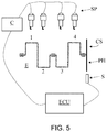
- FIG. 5 shows a preferred implementation of the present invention in the context of a positive ignition internal combustion engine
- FIG. 6 shows a preferred implementation of the present invention in the context of a diesel cycle internal combustion engine.
- second component does not imply the presence of a “first” component.
- the internal combustion engine comprises a plurality of cylinders.
- FIGS. 4 and 5 show only the first four cylinders 1 to 4 of a first bank of an engine comprising two V-shaped banks with a total of eight cylinders.
- the cylinders are connected to a single drive shaft CS to which a so-called phonic wheel is rigidly associated, to which a sensor S is in turn associated that is able to measure an (angular) speed of the drive shaft.
- a so-called phonic wheel is rigidly associated
- a sensor S is in turn associated that is able to measure an (angular) speed of the drive shaft.
- it uses the Hall effect, but other technologies can be used.
- FIG. 5 shows a positive ignition internal combustion engine showing the SP spark plugs that cause the air/fuel mixture to ignite in a corresponding cylinder 1 - 4 .
- FIG. 6 shows a diesel cycle internal combustion engine showing the diesel fuel injectors J that inject the fuel into a corresponding cylinder 1 - 4 .
- An ECU (Engine Control Unit) processing unit is operatively connected to said angular speed sensor S.
- the processing unit is programmed to acquire the signal generated by said sensor and to convert it into a signal in the frequency domain, for example by the Fourier transform.
- They are preferably processed acquisition ranges of said signal in which the same signal is averagely constant.
- a first ideal analysis condition can coincide with the idle condition of the internal combustion engine.
- a nominal frequency is defined based on the average angular rotation speed of the drive shaft, for example, 850 rpm corresponds to a nominal frequency of 14.17 Hz.
- FIGS. 1 and 3 Examples of frequency analysis of the angular speed of the internal combustion engine are given in FIGS. 1 and 3 .
- the signal in the frequency domain is analysed, preferably by the Fourier transform, at said half-order frequency.
- the Fourier transform is a function of the time domain with values in the complex plane. Therefore, it is possible to calculate the so-called phase spectrum of the function as arctan (Im(f)Re(f)) and in particular the phase fi(f) of the disturbance by substituting said half-order frequency to the variable f, e.g. 7 Hz if the engine is idling.
- phase value is correlated with the cylinder causing this imbalance.
- the plan is divided first into contiguous angular sectors numbered according to the same ignition sequence of the cylinders starting from a reference phase f (0), indicated in the Figure by the axis 0 .
- An example is given in FIG. 2 . Therefore, a 1:1 relationship is defined between the angular sectors and all the cylinders composing the internal combustion engine.
- the cylinder i is identified as the cause of this imbalance, which is the one whose angular sector comprises the aforesaid phase fi (f/2).
- the cylinder is identified when a counter exceeds a settable threshold, i.e. when the phase is stable after a predetermined number of iterations.
- This counter is reset every time the phase changes angular sector: in this way the identification takes place only after a sufficiently long time in order to reliably associate the calculated phase with the cylinder i.
- the initial problem may spontaneously end, e.g. due to impurities in the fuel that selectively hit a cylinder.
- a possible suppression strategy can cause a disturbance with an increase in the amplitude of the half-order frequency associated with a cylinder, which delivers, for example, more torque than the remaining cylinders.
- the second option b) is advantageous because it allows obtaining a quicker correction starting from the last correction carried out following the detection of the cylinder i as a cause of disturbance.
- the method for the identification of a torque delivery imbalance of an internal combustion engine equipped with two or more cylinders under constant speed operating conditions comprises in succession the following steps:
- the ECU processing unit can intervene on an operating parameter of a cylinder:
- the internal combustion engine is a positive ignition internal combustion engine and includes a post-treatment system of the exhausted gas allowing a lean combustion (lambda higher than 1), then either of the two or both of the previous strategies can be used in combination with each other.
- the timing of fuel injections and/or the total mass injected in each combustion cycle may be varied.
- the effected correction aims at obtaining a variation of the torque delivered by a cylinder that is judged to be the cause of the disturbance. Said variation is made in a discrete manner, namely with predetermined and adjustable amplitude corrections of an operating parameter of said cylinder.
- the amplitude of the half-order frequency is monitored regardless of the type of correction carried out. This provides a feedback on the exactness of the correction. If the amplitude is reduced, then the correction sign is correct, otherwise the correction sign is inverted until its amplitude is lower than said predetermined settable threshold Th. Therefore, the present suppression method is a closed loop control method.
- a disturbance suppression introduced by the previously identified cylinder is corrected by means of one of the following steps:
- the method is performed in closed loop and therefore also the following steps are carried out in succession:
- the correction continues by using the same correction sign or by inverting the correction sign until the amplitude of the half-order frequency is again below the threshold Th.
- the correction reduces the amplitude of the disturbance, it continues without inverting the correction sign, otherwise the sign is inverted and the correction is continued until the amplitude of the half-order frequency is reduced below the threshold Th.
- said first trend is low pass filtered in order to identify an improving or worsening trend of the correction action carried out with respect to the first trend acquired before the correction.
- FIG. 3 shows two overlapping curves. The more jagged one identifies said second trend, while the filtered, more smoothed one identifies the first signal. Their overlapping shows that the correction tends to limit the amplitude of the second trend with a correction made with the correct sign.
- a similar comparison can be made by comparing the integrals of said first and second trends.
- said integrals are obtained after the low pass filtering of both trends.
- the disturbance suppression provides a correction (ixa) of the torque delivered by said cylinder i and/or a correction (ixb, ixc) of the torque delivered by the remaining cylinders.
- This torque correction can be positive or negative.
- the suppression procedure ends, maintaining the last correction, while the monitoring of the amplitude of the half-order frequency can continue.
- FIG. 4 a proposes a flowchart of an example of a preferred implementation of the present invention by implementing the detection of an imbalance, the identification of the cylinder that causes this imbalance as well as the relative suppression by taking into account any previous suppression:
- the use of the flag is convenient for detecting when a correction procedure on a cylinder is completed or evolving.
- step 15 reports “first cylinder i previously subjected to correction”, it means that its correction has been completed by setting the flag to zero.
- the present method allows checking whether the intervention is correct and in case inverting the correction sign.
- the strategy is also able to intervene on the second cylinder by correcting the delivered torque.
- the second cylinder j is opposite the first cylinder i, it is preferable to operate backwards, i.e. by inverting the sign of the last correction made on the cylinder i until the amplitude of the half-order frequency falls below the threshold Th.
- Another ideal condition to detect a torque delivery imbalance occurs when the angular speed of the drive shaft is higher than the idling speed and is averagely constant over a predetermined time range.
- This time range must be long enough to allow the acquisitions necessary for steps 10 and 17 .
- This control strategy unlike the previous one, can be performed under any operating condition of the internal combustion engine.
- this control strategy can be combined with the previous one, which instead must be actuated at idling speed. This means that at idling speed the previous control strategy prevails, whereas the present control strategy works at engine speeds higher than the idling speed.
- the advance of the cylinder i or of the relative opposite cylinder j and/or of the remaining cylinders may be gradually varied.
- the procedure corrects the advance of the cylinder i both in positive and in negative, as in the previous example.
- the diagram of FIG. 4 can therefore be modified to check whether the cylinder causing the disturbance has set the maximum advance. If so, the procedure reduces the advance of the opposite cylinder up to a certain reduction threshold.
- the torque delivered by the cylinder no. 5 can be reduced by delta and the torque delivered by the remaining cylinders no. 2 -no. 4 , no. 6 -no. 8 can be reduced by delta/h, where h is a parameter that can be calibrated, e.g. it can be equal to 2 or equal to the number N ⁇ 1, where N represents the number of cylinders, which in the example is equal to 8.
- the torque delivered by the cylinder no. 5 can be gradually reduced up to a certain reduction threshold.
- a further control can be introduced and as the cylinder to be corrected can be set the one that actually causes the disturbance i or its opposite j based on the advance value set on the cylinder i causing the disturbance, with respect to a relative predetermined maximum advance value.
- the fuel injection control can be advantageously performed in diesel cycle internal combustion engines as there are no stringent restrictions in the stoichiometry of the combustion or in the positive ignition engines with an ATS that allows them to operate even in conditions of lean mixture.
- This control strategy can be applied both at idling speed and at other rpms.
- the fuel injection can be corrected by checking the fuel microinjections, their timing and/or the total mass of fuel injected at each combustion cycle in the cylinder i and/or in the remaining cylinders.
- the present invention can be advantageously implemented by means of a computer program, which comprises coding means for implementing one or more steps of the method, when this program is run on a computer. Therefore, the scope of protection extends to said computer program and also to computer readable means comprising a recorded message, said computer readable means comprising program coding means for implementing one or more steps of the method when said program is run on a computer.
Landscapes
- Engineering & Computer Science (AREA)
- Chemical & Material Sciences (AREA)
- Combustion & Propulsion (AREA)
- Mechanical Engineering (AREA)
- General Engineering & Computer Science (AREA)
- Combined Controls Of Internal Combustion Engines (AREA)
- Output Control And Ontrol Of Special Type Engine (AREA)
- Exhaust-Gas Circulating Devices (AREA)
- Electrical Control Of Air Or Fuel Supplied To Internal-Combustion Engine (AREA)
Abstract
Description
-
- low manufacturing tolerances of the relative components, from the crank mechanisms to the valves to the fuel injectors;
- engine assembling ability,
- combustion control system of each cylinder.
-
- a) the previous corrections are cancelled and the disturbance monitoring is restarted, or
- b) it is identified the cylinder j that is currently causing the disturbance. If the cylinder j corresponds to the angular sector opposite the one previously associated with the cylinder i, then the cause of the disturbance is considered the same disturbance suppression strategy implemented on the previously corrected cylinder i, otherwise the cylinder j is considered the cause of the new disturbance.
-
- (i) acquiring a first signal of a rotation speed of a relative drive shaft (CS) by means of a speed sensor;
- (ii) converting said first signal into a second signal in the frequency domain, (iia) calculating a first amplitude (A=Re(f/2)) of a predetermined frequency (f/2) equal to half a frequency (f) relative to said averagely constant speed;
- (iii) comparing said first amplitude (A) with a predetermined threshold (Th) and if said first amplitude exceeds said predetermined threshold, then
- (iv) an imbalance of the internal combustion engine has been identified.
-
- (iib) calculating a first phase (fi(f/2)) relative to a first amplitude (Re(f/2)) with respect to a reference phase (f(0));
- (v) preliminary dividing a plane into angular sectors in numbers corresponding to a number (N) of said two or more cylinders and numbering said sectors consecutively according to an ignition order of said internal combustion engine starting from a reference phase (0);
- (vi) identifying said first cylinder (i) that causes said imbalance by identifying a corresponding sector (i) to which said first phase (fi(f/2)) belongs.
Disturbance Suppression
-
- on the ignition advance, in the case of a positive ignition internal combustion engine,
- on the fuel injection, in the case of a self-ignition, i.e. a diesel cycle internal combustion engine.
-
- (ixa) a first correction of an operating parameter of said first cylinder, or
- (ixb) a second correction of an operating parameter of a second cylinder (j) opposite said first cylinder, or
- (ixc) a third correction of an operating parameter of the remaining cylinders with respect to said first cylinder.
-
- (xi) acquiring a second signal of said rotation speed of a relative drive shaft (CS) by means of a speed sensor;
- (xii) converting said second signal into a second signal in the frequency domain, (xiia) calculating a second amplitude (A′=Re(f/2)) of said predetermined frequency;
- (xiii) comparing said first amplitude with said second amplitude and if said second amplitude exceeds said first amplitude, then
- (xiv) inverting a sign of said correction and carrying out said first, second or third correction of said parameter according to any one of the possible aforesaid options ixa, ixb, ixc, or, if said first amplitude exceeds said second amplitude, then
- (ix) correcting said parameter according to one of said aforesaid options without obviously varying the sign previously used for the previous correction.
-
- the index of the cylinder (i-mo) object of the last correction;
- which correction has been made on the same cylinder or on the opposite one and/or on the remaining cylinders (ixa, ixb, ixc);
- said sign of said last correction.
-
- (step 10) (iia) first acquisition of a first time sample of the rotation speed signal of the drive shaft and first calculation of a first amplitude A of the half-order disturbance;
- (step 11) (iii) comparing said amplitude with a predetermined threshold (Th) and if said amplitude does not exceed said predetermined threshold (
step 11=NO) then a flag is set to zero (F0) and the procedure is restarted from the beginning (step 10), otherwise (step 11=YES) - (step 12) checking whether a first cylinder i that generates the imbalance has already been identified at the previous recursion, and if it had been previously identified (
step 12=YES), then - (step 14) correcting an operating parameter of said first cylinder i;
- if instead the cylinder had not been corrected in the previous recursion (
step 12=NO), then - (step 13) (iib) calculating the phase of the half-order frequency (fi (f/2)) by identifying a second cylinder j;
- (step 15) checking whether said second cylinder j is a cylinder opposite—at less than 180°—a first cylinder i previously subjected to correction, and if the check is positive (
step 15=YES), then - (step 16) correcting an operating parameter of said first cylinder i, otherwise (
step 15=NO) correcting (step 14) an operating parameter of the identified second cylinder j; then - (step 17) second acquisition of a second time sample of the rotation speed signal of the drive shaft acquired after said correction (
steps 14 or 16) and second calculation of a second amplitude A′ of the half-order disturbance; - (step 18) checking whether said second amplitude A′ is lower than said first amplitude A; in the positive case (17=YES), then
- (step 19) maintaining an unchanged sign of said correction, setting to 1 the flag (F1) and starting again from the beginning (step 10), otherwise (
step 17=NO) - (step 20) inverting a sign of said correction, setting to 1 the flag (F1) and starting again from the beginning (step 10).
Claims (22)
Applications Claiming Priority (2)
| Application Number | Priority Date | Filing Date | Title |
|---|---|---|---|
| IT201800001107A IT201800001107A1 (en) | 2018-01-16 | 2018-01-16 | SYSTEM OF IDENTIFICATION AND SUPPRESSION OF A TORQUE DELIVERY UNBALANCE OF AN INTERNAL COMBUSTION ENGINE EQUIPPED WITH TWO OR MORE CYLINDERS |
| IT102018000001107 | 2018-01-16 |
Publications (2)
| Publication Number | Publication Date |
|---|---|
| US20190218982A1 US20190218982A1 (en) | 2019-07-18 |
| US10830165B2 true US10830165B2 (en) | 2020-11-10 |
Family
ID=62002222
Family Applications (1)
| Application Number | Title | Priority Date | Filing Date |
|---|---|---|---|
| US16/248,212 Active 2039-02-06 US10830165B2 (en) | 2018-01-16 | 2019-01-15 | Identification and suppression system of a torque delivery imbalance of an internal combustion engine equipped with two or more cylinders |
Country Status (3)
| Country | Link |
|---|---|
| US (1) | US10830165B2 (en) |
| EP (1) | EP3511554B1 (en) |
| IT (1) | IT201800001107A1 (en) |
Families Citing this family (1)
| Publication number | Priority date | Publication date | Assignee | Title |
|---|---|---|---|---|
| CN116009501B (en) * | 2023-03-22 | 2023-06-16 | 山东瑞芝生物科技股份有限公司 | Primary pulp production machine management and control system based on data analysis |
Citations (14)
| Publication number | Priority date | Publication date | Assignee | Title |
|---|---|---|---|---|
| US4301678A (en) * | 1979-12-20 | 1981-11-24 | United Technologies Corporation | Relative power contribution of an internal combustion engine |
| US20020148441A1 (en) | 2001-03-02 | 2002-10-17 | Taner Tuken | On-line individual fuel injector diagnostics from instantaneous engine speed measurements |
| US20030089338A1 (en) | 2000-11-07 | 2003-05-15 | Joerg Remele | Regulation of true running for diesel engines |
| US20050229904A1 (en) | 2002-07-31 | 2005-10-20 | Reinhold Hagel | Regulating the mode of operation of an internal combustion engine |
| US20070175443A1 (en) | 2005-12-05 | 2007-08-02 | Matthias Schueler | Method for controlling the quantity of fuel and/or air to an internal combustion engine on a cylinder-by-cylinder basis |
| US20080276697A1 (en) | 2005-11-30 | 2008-11-13 | Wartsila Finland Oy | Apparatus for Identifying a Non-Uniform Share of Cylinder Power in an Internal Combustion Piston Engine System |
| US20090037060A1 (en) * | 2006-03-09 | 2009-02-05 | Volvo Technology Corporation | Hybrid powertrain and method for controlling a hybrid powertrain |
| US20100039076A1 (en) * | 2008-08-12 | 2010-02-18 | Rolls-Royce Plc | Electromechanical arrangement |
| US20140347043A1 (en) * | 2012-01-09 | 2014-11-27 | Isis Innovation Limited | Monitoring engine components |
| EP2843219A1 (en) | 2012-04-24 | 2015-03-04 | Toyota Jidosha Kabushiki Kaisha | Control device for internal combustion engine |
| US20170122839A1 (en) * | 2015-11-03 | 2017-05-04 | MAGNETI MARELLI S.p.A. | Method of estimating the mfb50 combustion index and the instantaneous torque generated by the cylinders of an internal combustion engine |
| US20170241369A1 (en) * | 2016-02-24 | 2017-08-24 | Ford Global Technologies, Llc | Method for reducing cylinder air-fuel ratio imbalance |
| US20170254726A1 (en) | 2016-03-07 | 2017-09-07 | General Electric Company | Method and systems for diagnosing an engine |
| US20200040988A1 (en) * | 2018-08-02 | 2020-02-06 | GM Global Technology Operations LLC | Torque converter clutch control system health estimation |
-
2018
- 2018-01-16 IT IT201800001107A patent/IT201800001107A1/en unknown
-
2019
- 2019-01-15 US US16/248,212 patent/US10830165B2/en active Active
- 2019-01-16 EP EP19152188.9A patent/EP3511554B1/en active Active
Patent Citations (14)
| Publication number | Priority date | Publication date | Assignee | Title |
|---|---|---|---|---|
| US4301678A (en) * | 1979-12-20 | 1981-11-24 | United Technologies Corporation | Relative power contribution of an internal combustion engine |
| US20030089338A1 (en) | 2000-11-07 | 2003-05-15 | Joerg Remele | Regulation of true running for diesel engines |
| US20020148441A1 (en) | 2001-03-02 | 2002-10-17 | Taner Tuken | On-line individual fuel injector diagnostics from instantaneous engine speed measurements |
| US20050229904A1 (en) | 2002-07-31 | 2005-10-20 | Reinhold Hagel | Regulating the mode of operation of an internal combustion engine |
| US20080276697A1 (en) | 2005-11-30 | 2008-11-13 | Wartsila Finland Oy | Apparatus for Identifying a Non-Uniform Share of Cylinder Power in an Internal Combustion Piston Engine System |
| US20070175443A1 (en) | 2005-12-05 | 2007-08-02 | Matthias Schueler | Method for controlling the quantity of fuel and/or air to an internal combustion engine on a cylinder-by-cylinder basis |
| US20090037060A1 (en) * | 2006-03-09 | 2009-02-05 | Volvo Technology Corporation | Hybrid powertrain and method for controlling a hybrid powertrain |
| US20100039076A1 (en) * | 2008-08-12 | 2010-02-18 | Rolls-Royce Plc | Electromechanical arrangement |
| US20140347043A1 (en) * | 2012-01-09 | 2014-11-27 | Isis Innovation Limited | Monitoring engine components |
| EP2843219A1 (en) | 2012-04-24 | 2015-03-04 | Toyota Jidosha Kabushiki Kaisha | Control device for internal combustion engine |
| US20170122839A1 (en) * | 2015-11-03 | 2017-05-04 | MAGNETI MARELLI S.p.A. | Method of estimating the mfb50 combustion index and the instantaneous torque generated by the cylinders of an internal combustion engine |
| US20170241369A1 (en) * | 2016-02-24 | 2017-08-24 | Ford Global Technologies, Llc | Method for reducing cylinder air-fuel ratio imbalance |
| US20170254726A1 (en) | 2016-03-07 | 2017-09-07 | General Electric Company | Method and systems for diagnosing an engine |
| US20200040988A1 (en) * | 2018-08-02 | 2020-02-06 | GM Global Technology Operations LLC | Torque converter clutch control system health estimation |
Non-Patent Citations (1)
| Title |
|---|
| Search Report for IT Application No. 2018000001107, search completed Sep. 7, 2018 (8 pages). |
Also Published As
| Publication number | Publication date |
|---|---|
| EP3511554B1 (en) | 2021-08-18 |
| EP3511554A1 (en) | 2019-07-17 |
| US20190218982A1 (en) | 2019-07-18 |
| IT201800001107A1 (en) | 2019-07-16 |
Similar Documents
| Publication | Publication Date | Title |
|---|---|---|
| JP4096924B2 (en) | Injection amount control device for internal combustion engine | |
| US5111405A (en) | Engine control system | |
| JP3861550B2 (en) | Abnormal cylinder detection device for multi-cylinder internal combustion engine | |
| JP5772634B2 (en) | Control device for multi-cylinder internal combustion engine | |
| US12163495B2 (en) | Control apparatus for internal combustion engine | |
| JP2001234800A (en) | Fuel injection control device | |
| US8977471B2 (en) | Controller for internal combustion engine | |
| US10677180B2 (en) | Controller and control method for internal combustion engine | |
| US10830165B2 (en) | Identification and suppression system of a torque delivery imbalance of an internal combustion engine equipped with two or more cylinders | |
| GB2343220A (en) | Internal combustion engine knock detection | |
| US20010020465A1 (en) | Method for detecting combustion misfires and cylinder equalization in internal combustion engines with knock control | |
| JP3498392B2 (en) | Electronic control fuel injection device | |
| JP3876766B2 (en) | Injection rate control device for internal combustion engine | |
| JP3695411B2 (en) | Fuel injection control device for internal combustion engine | |
| JPH08218917A (en) | Engine controller | |
| JP6156293B2 (en) | Fuel injection control device for internal combustion engine | |
| US20190186406A1 (en) | Controller for internal combustion engine | |
| JP6219609B2 (en) | Engine start control device | |
| JP5648646B2 (en) | Fuel injection control device | |
| US5967117A (en) | Method for determining a rotational speed for an idling control of an internal combustion engine | |
| JP4389400B2 (en) | Fuel injection device | |
| US12163858B2 (en) | Misfire determination device for internal combustion engine | |
| US20230235713A1 (en) | Control apparatus for engine | |
| JP2007032557A (en) | Fuel injection control device | |
| JP2920262B2 (en) | Control device for multi-cylinder internal combustion engine |
Legal Events
| Date | Code | Title | Description |
|---|---|---|---|
| FEPP | Fee payment procedure |
Free format text: ENTITY STATUS SET TO UNDISCOUNTED (ORIGINAL EVENT CODE: BIG.); ENTITY STATUS OF PATENT OWNER: LARGE ENTITY |
|
| STPP | Information on status: patent application and granting procedure in general |
Free format text: DOCKETED NEW CASE - READY FOR EXAMINATION |
|
| STPP | Information on status: patent application and granting procedure in general |
Free format text: NON FINAL ACTION MAILED |
|
| STPP | Information on status: patent application and granting procedure in general |
Free format text: NOTICE OF ALLOWANCE MAILED -- APPLICATION RECEIVED IN OFFICE OF PUBLICATIONS |
|
| AS | Assignment |
Owner name: FERRARI S.P.A., ITALY Free format text: ASSIGNMENT OF ASSIGNORS INTEREST;ASSIGNORS:TOMBARI, LORENZO;SARTONI, GIOVANNI;GENOVA, DANIELE;REEL/FRAME:053974/0225 Effective date: 20200929 |
|
| STPP | Information on status: patent application and granting procedure in general |
Free format text: PUBLICATIONS -- ISSUE FEE PAYMENT VERIFIED |
|
| STCF | Information on status: patent grant |
Free format text: PATENTED CASE |
|
| MAFP | Maintenance fee payment |
Free format text: PAYMENT OF MAINTENANCE FEE, 4TH YEAR, LARGE ENTITY (ORIGINAL EVENT CODE: M1551); ENTITY STATUS OF PATENT OWNER: LARGE ENTITY Year of fee payment: 4 |