US1081663A - Computing device. - Google Patents
Computing device. Download PDFInfo
- Publication number
- US1081663A US1081663A US75717413A US1913757174A US1081663A US 1081663 A US1081663 A US 1081663A US 75717413 A US75717413 A US 75717413A US 1913757174 A US1913757174 A US 1913757174A US 1081663 A US1081663 A US 1081663A
- Authority
- US
- United States
- Prior art keywords
- sheet
- rollers
- casing
- calculating
- numbers
- Prior art date
- Legal status (The legal status is an assumption and is not a legal conclusion. Google has not performed a legal analysis and makes no representation as to the accuracy of the status listed.)
- Expired - Lifetime
Links
Images

Classifications
-
- G—PHYSICS
- G06—COMPUTING OR CALCULATING; COUNTING
- G06C—DIGITAL COMPUTERS IN WHICH ALL THE COMPUTATION IS EFFECTED MECHANICALLY
- G06C3/00—Arrangements for table look-up, e.g. menstruation table
-
- G—PHYSICS
- G06—COMPUTING OR CALCULATING; COUNTING
- G06G—ANALOGUE COMPUTERS
- G06G1/00—Hand-manipulated computing devices
Definitions
- nuFFIEIn nuFFIEIn
- ⁇ nnNDALnv1LLE,-rND1AnA, nssrmvon Aor onnrnarr To sur State of Indiana have invented certain new Iand. useful Improvements in Computing Devices, of which the following is a specifica' tion.
- This invention relates to an improved -computing or calculating device for rapidly multiplying given numbers without mathematical calculation, and has for its object to produce a device of thisA character which will have a very large range in respect to the numbers to be calculated, which will be very compact in structure, and which will be so simple as to render mistakes impossible.
- a further object of the invention resides in the provision of a calculating sheet or strip upon which is arranged a plurality of predetermined numbers, the said sheet being operated in connection with a pair of parallel .rol-lersor cylindrical members in such a novel and peculiar manner as to permit use of both, sides or faces of the said sheet for calculati v purposes.
- a still urther ob]ec t of the invention contemplates the provision of a computing device of the above character embodied in convenient form for use and operation inthe hand or upon.the desk of the user.
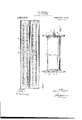
- Figure 1 is an end View of a device or machine constructed in accordance with my invention
- Fig. 2 is a vertical sectional view, with the supports removed.
- Fig. 3v is an elevation, with the casing removed;
- Fig. 4 is a vertical sectional view, with the casing removed;
- Fig. 5' is a top plan view of the device with the casing removed.
- crank handle 10 secured atone end of the lower shaft 8.
- Gear wheels 11'- and 12 are formed upon the extremities ofthe rollers 2 and 3 respectively to impart motion to the roller 3 accordingv to the rotation of the roller 2 created by the manipulation of the crank handle 10.
- the'saidrollers are spaced suiciently apart to permit free rotation of one,"without frictional engagement with the other and-'will cause one. of the said rollers torotate in one direction while the other rolleris rotated in the. opposite direction for -eifecting-the desired ,result necessary in' carrying out the invention.
- Phe outer shell or casing within which the rollers and gear wheels are contained is provided.
- the said numbers indicating the multiplier of the problem to be determined or calculated while the said numerals from 1 to 100 and from 1% to 84.1,- represent the multiplica-nd.
- I provide predetermined numerals comprising the product or the result of the calculation desired.
- the turningof the crank handle. 10 will shift the position of the sheet 14: upon the rollers and will bring the desired numeral or multiplier' at the For instance, the machine may be stopped at 11; and if you desire to multiply 11 by 27 all that is necessary is to glance at the numeral 27 of the multiplicand and the product or result which is Q97, the latter being placed in the space 18 of the sheet directly beneath the numeral 27. If an uneven number is t0 be calculated for example,
- both sides or' faces of the sheet 14 are utilized for computing or calculating purposes; that the operation of thel 'crank handle 10 for shifting the numerals upon the said sheet is all that is necessary to calculate or obtain the product of the example 'zo be computed; and that the provision or the eccentric pivotal mounting of the casing will allow the entire machine to be tilted or swung into a more convenient position.
- a calculating device including in combination a pair of spaced apart upright supports, the said supports each having an arcuate alined slot formed therein, a casing e'cccntrically pivoted between the said supports, the said casing having sight openings formed therein, a pair of parallel spaced apart rollers mounted within said casing, shafts upon which said rollers are rigidly mounted, one of said shafts adapted to ex tend through the said slots to provide for the tilting of the casing from the eccentric pivot point, means including meshing gears mounted one upon each of the said shafts for simultaneously rotating the said rollers in an opposite direction, means for rotating one of said shafts, and a calculating sheet having numerals arranged upon each side thereof, the saidshect adapted to be wound oppositely upon the said rollers for exposing to view the said numerals through the said sight openings of the casing during the rotation ot' the rollers, as and for the purpose set forth.
Landscapes
- Engineering & Computer Science (AREA)
- Theoretical Computer Science (AREA)
- Physics & Mathematics (AREA)
- Computer Hardware Design (AREA)
- General Physics & Mathematics (AREA)
- Computing Systems (AREA)
- Sheet Holders (AREA)
Description
GOMEUTNG DEVICE.
APPLIGATIN FILED $1311.27. 191;.
Patented Deo. 16, .1913.
2 SHEETS-SHEET 1.
C. D. DUFFIELD. COMPUTING DEVICE.
APPLIQATION FILED Mu?, 1913.
Patented Dec. 16, 1913.
2 SHEETS-SHEET 2.
tention to the andren ,15. nuFFIEIn; or `nnNDALnv1LLE,-rND1AnA, nssrmvon Aor onnrnarr To sur State of Indiana, have invented certain new Iand. useful Improvements in Computing Devices, of which the following is a specifica' tion.
This invention relates to an improved -computing or calculating device for rapidly multiplying given numbers without mathematical calculation, and has for its object to produce a device of thisA character which will have a very large range in respect to the numbers to be calculated, which will be very compact in structure, and which will be so simple as to render mistakes impossible.
A further object of the invention resides in the provision of a calculating sheet or strip upon which is arranged a plurality of predetermined numbers, the said sheet being operated in connection with a pair of parallel .rol-lersor cylindrical members in such a novel and peculiar manner as to permit use of both, sides or faces of the said sheet for calculati v purposes.
A still urther ob]ec t of the invention, contemplates the provision of a computing device of the above character embodied in convenient form for use and operation inthe hand or upon.the desk of the user.
The above and additional objects are accomplished by such means as are illustrated in their preferred embodiment in the accom panying drawings, described in the follow ing specification andl then more particularly pointed out in the claim which is appended hereto and forms a part of vthis application.
In describing my invention in detail reference will be had to the accompanying drawings wherein like characte denote like or corresponding parts throughout the several views, and in which l Figure 1 is an end View of a device or machine constructed in accordance with my invention; Fig. 2 is a vertical sectional view, with the supports removed. Fig. 3v is an elevation, with the casing removed; Fig. 4
the calculating sheets arranged thereupon;` and Fig. 5' is a top plan view of the device with the casing removed.
Before proceeding with the drawings, I desire to call fact that while-I have evolved the description of particular atl SG'HUTT, OF'KENDALLVILLE, INDIANA.
f Cormru'riive nlivreis.I
`my invention with reference to thefmultiplyingk of various numerals, the same may be readily utilized for adding, subtracting or otherwise calculating numerals.
Referring now to the drawings, whereinl is. illustrated the preferred formvof my invention the numeral l designates an upright specification of Leners Intent." Patented De@ '16"19'1'3 Application filed March 27, 19,13. Serial No. 757,174..
of novel and peculiar form,'there being two, one at each end of the machine, between which a pair of parallel rollersor cylindrical members 2 and 3- are disposed. The upper extremity of the supports lphave an extension l f irmed integrally therewith, the said extension eectingan eccentric pivot point as at 5 for the outer shell or casing 6 of the machine. An arcuate slot 7 is formed within the supports l, the curvature of the `said slot being described from the eccentric pivot point 5. By the provision of the said slot .7, a tilting` of the entire machine, eX- cludi-ng. the supports is permitted, the tilted portion of the machine beingswung upon the eccentric pivotal connection 'designated as at 5 in Fig. l of'thedrawings. vTwo parallel shafts 8 and 9 respectively --extend through the rollers 2 and 3- of the machine for xedly supporting the said rollers. and
imparting motionthereto throughk the medi;
um ot a crank handle 10 secured atone end of the lower shaft 8. Gear wheels 11'- and 12 are formed upon the extremities ofthe rollers 2 and 3 respectively to impart motion to the roller 3 accordingv to the rotation of the roller 2 created by the manipulation of the crank handle 10. By the provision ofthe -gear wheels lland 12 it will beseen that the'saidrollers are spaced suiciently apart to permit free rotation of one,"without frictional engagement with the other and-'will cause one. of the said rollers torotate in one direction while the other rolleris rotated in the. opposite direction for -eifecting-the desired ,result necessary in' carrying out the invention. Phe outer shell or casing within which the rollers and gear wheels are contained is provided. withv a pain ofv trans parent depressions 13 extending parallel with and throughout the entire length of the saidk rollers 2 and 3, the said depressed -portions of the casing effecting a sightopening for exposing to view the interior mechanism contained within the saidcasing.
Having described fully the mechanical struc-ture of the. device, the 'operation and arrangement of the -calculating sheet 14 .of the=- lower roller 2.
'sight opening 13 of either roller.
secured to the outer face 'of the lower roller 2 and is wound thereupon, once, twice or any number of times desired and extends from the said yroller as at 1 5 to the upper roller 3 upon which it is also wound the desired number of times and secured to the outer face at any 'suitable;point.` Arranged at predetermined ypoints upon one face of the sheet 14 so as to be exposed to view through the sight :opening 13 of the upper roller, are aplurality of numbers ranging from 1 to 100, while the opposite face of the said sheet 14 is provided with a plurality of numbers ranging from 1% to 84%, the said last mentioned numbers being exposed to view through the sight opening 13 Numbers. ranging from 2 upwardlyf are arranged upon the blankspacel 16 ofthe sheet 14, the said numbers indicating the multiplier of the problem to be determined or calculated while the said numerals from 1 to 100 and from 1% to 84.1,- represent the multiplica-nd. Between the said rows of numbers 17, the latter being divided and arranged oppositely or in rows upon the calculating sheet 14, I provide predetermined numerals comprising the product or the result of the calculation desired.
In operation, the turningof the crank handle. 10 will shift the position of the sheet 14: upon the rollers and will bring the desired numeral or multiplier' at the For instance, the machine may be stopped at 11; and if you desire to multiply 11 by 27 all that is necessary is to glance at the numeral 27 of the multiplicand and the product or result which is Q97, the latter being placed in the space 18 of the sheet directly beneath the numeral 27. If an uneven number is t0 be calculated for example,
11 by 65;, a glance at 65;;- will show 720%-- dircctly therebeneath, the product of such multiplication.
It will be seenfrom the above, taken in connection with the accompanying drawings that both sides or' faces of the sheet 14 are utilized for computing or calculating purposes; that the operation of thel 'crank handle 10 for shifting the numerals upon the said sheet is all that is necessary to calculate or obtain the product of the example 'zo be computed; and that the provision or the eccentric pivotal mounting of the casing will allow the entire machine to be tilted or swung into a more convenient position.
lI desire to emphasize the fact that various minor changes in details of construction, proportion and arrangement of parts may be resorted to, when required, without sacriicing any of the advantages of my invention, as defined in the appended claim.
Having thus Afuiiy described my invention, what I claim as new and desire to secure by LettersPatent, is
A calculating device including in combination a pair of spaced apart upright supports, the said supports each having an arcuate alined slot formed therein, a casing e'cccntrically pivoted between the said supports, the said casing having sight openings formed therein, a pair of parallel spaced apart rollers mounted within said casing, shafts upon which said rollers are rigidly mounted, one of said shafts adapted to ex tend through the said slots to provide for the tilting of the casing from the eccentric pivot point, means including meshing gears mounted one upon each of the said shafts for simultaneously rotating the said rollers in an opposite direction, means for rotating one of said shafts, and a calculating sheet having numerals arranged upon each side thereof, the saidshect adapted to be wound oppositely upon the said rollers for exposing to view the said numerals through the said sight openings of the casing during the rotation ot' the rollers, as and for the purpose set forth.
In testimony wher-cci" l aliix my signature in presence of two witnesses.
CLOYCE D. DUFFIELD. Vitnesses GUY A. SGHUTT, J. AUSTIN JONES.
Priority Applications (1)
| Application Number | Priority Date | Filing Date | Title |
|---|---|---|---|
| US75717413A US1081663A (en) | 1913-03-27 | 1913-03-27 | Computing device. |
Applications Claiming Priority (1)
| Application Number | Priority Date | Filing Date | Title |
|---|---|---|---|
| US75717413A US1081663A (en) | 1913-03-27 | 1913-03-27 | Computing device. |
Publications (1)
| Publication Number | Publication Date |
|---|---|
| US1081663A true US1081663A (en) | 1913-12-16 |
Family
ID=3149896
Family Applications (1)
| Application Number | Title | Priority Date | Filing Date |
|---|---|---|---|
| US75717413A Expired - Lifetime US1081663A (en) | 1913-03-27 | 1913-03-27 | Computing device. |
Country Status (1)
| Country | Link |
|---|---|
| US (1) | US1081663A (en) |
Cited By (2)
| Publication number | Priority date | Publication date | Assignee | Title |
|---|---|---|---|---|
| US10956854B2 (en) | 2017-10-20 | 2021-03-23 | BXB Digital Pty Limited | Systems and methods for tracking goods carriers |
| US10977460B2 (en) | 2017-08-21 | 2021-04-13 | BXB Digital Pty Limited | Systems and methods for pallet tracking using hub and spoke architecture |
-
1913
- 1913-03-27 US US75717413A patent/US1081663A/en not_active Expired - Lifetime
Cited By (2)
| Publication number | Priority date | Publication date | Assignee | Title |
|---|---|---|---|---|
| US10977460B2 (en) | 2017-08-21 | 2021-04-13 | BXB Digital Pty Limited | Systems and methods for pallet tracking using hub and spoke architecture |
| US10956854B2 (en) | 2017-10-20 | 2021-03-23 | BXB Digital Pty Limited | Systems and methods for tracking goods carriers |
Similar Documents
| Publication | Publication Date | Title |
|---|---|---|
| US1081663A (en) | Computing device. | |
| US1502662A (en) | Game-score register | |
| US3310896A (en) | Apparatus for displaying insurance data | |
| US1248017A (en) | Automatic rewinding device for stenotype-note holders. | |
| US986433A (en) | Display-stand. | |
| US718104A (en) | Registering mechanism. | |
| US1111174A (en) | Drafting instrument. | |
| US786102A (en) | Calculator. | |
| US2230990A (en) | Measuring instrument | |
| JP2005152222A5 (en) | ||
| US641517A (en) | Automatic computing-machine. | |
| US1090626A (en) | Score indicating and recording device. | |
| US551520A (en) | Calculating-machine for weights and values | |
| US896710A (en) | Computer. | |
| US862232A (en) | Calculating device. | |
| US947064A (en) | Educational device. | |
| US704114A (en) | Computing-machine. | |
| US3557476A (en) | Viewing device for microprint | |
| US951375A (en) | Game-counter. | |
| US1552516A (en) | Gear case | |
| US978950A (en) | Automatic computing device and cash-drawer. | |
| US1134924A (en) | Machine for measuring and rolling wall-paper. | |
| US1751082A (en) | Accounting device | |
| US677952A (en) | Educational appliance. | |
| US2510391A (en) | Logarithmic calculator |