US10816053B2 - Hydraulic brake - Google Patents
Hydraulic brake Download PDFInfo
- Publication number
- US10816053B2 US10816053B2 US16/169,539 US201816169539A US10816053B2 US 10816053 B2 US10816053 B2 US 10816053B2 US 201816169539 A US201816169539 A US 201816169539A US 10816053 B2 US10816053 B2 US 10816053B2
- Authority
- US
- United States
- Prior art keywords
- hydraulic pressure
- piston
- cylinder body
- cylinder
- rotor
- Prior art date
- Legal status (The legal status is an assumption and is not a legal conclusion. Google has not performed a legal analysis and makes no representation as to the accuracy of the status listed.)
- Expired - Fee Related, expires
Links
- 239000004918 carbon fiber reinforced polymer Substances 0.000 claims description 9
- 239000012530 fluid Substances 0.000 description 11
- 230000008878 coupling Effects 0.000 description 10
- 238000010168 coupling process Methods 0.000 description 10
- 238000005859 coupling reaction Methods 0.000 description 10
- 238000001514 detection method Methods 0.000 description 10
- 238000003825 pressing Methods 0.000 description 10
- 238000012423 maintenance Methods 0.000 description 6
- 238000005452 bending Methods 0.000 description 3
- 238000010586 diagram Methods 0.000 description 3
- 230000005484 gravity Effects 0.000 description 3
- 238000004519 manufacturing process Methods 0.000 description 3
- 238000000034 method Methods 0.000 description 3
- 230000002093 peripheral effect Effects 0.000 description 3
- 229920000049 Carbon (fiber) Polymers 0.000 description 2
- XEEYBQQBJWHFJM-UHFFFAOYSA-N Iron Chemical compound [Fe] XEEYBQQBJWHFJM-UHFFFAOYSA-N 0.000 description 2
- 230000009471 action Effects 0.000 description 2
- 239000004917 carbon fiber Substances 0.000 description 2
- 238000003754 machining Methods 0.000 description 2
- 230000036544 posture Effects 0.000 description 2
- 238000012545 processing Methods 0.000 description 2
- 238000004891 communication Methods 0.000 description 1
- 238000005520 cutting process Methods 0.000 description 1
- 238000013016 damping Methods 0.000 description 1
- 230000000694 effects Effects 0.000 description 1
- 238000007667 floating Methods 0.000 description 1
- 238000010348 incorporation Methods 0.000 description 1
- 238000003780 insertion Methods 0.000 description 1
- 230000037431 insertion Effects 0.000 description 1
- 229910052742 iron Inorganic materials 0.000 description 1
- 239000000463 material Substances 0.000 description 1
- 230000009467 reduction Effects 0.000 description 1
- 239000011347 resin Substances 0.000 description 1
- 229920005989 resin Polymers 0.000 description 1
- 238000003860 storage Methods 0.000 description 1
- 239000000725 suspension Substances 0.000 description 1
Images


Classifications
-
- F—MECHANICAL ENGINEERING; LIGHTING; HEATING; WEAPONS; BLASTING
- F16—ENGINEERING ELEMENTS AND UNITS; GENERAL MEASURES FOR PRODUCING AND MAINTAINING EFFECTIVE FUNCTIONING OF MACHINES OR INSTALLATIONS; THERMAL INSULATION IN GENERAL
- F16D—COUPLINGS FOR TRANSMITTING ROTATION; CLUTCHES; BRAKES
- F16D65/00—Parts or details
- F16D65/38—Slack adjusters
- F16D65/72—Slack adjusters hydraulic
-
- F—MECHANICAL ENGINEERING; LIGHTING; HEATING; WEAPONS; BLASTING
- F16—ENGINEERING ELEMENTS AND UNITS; GENERAL MEASURES FOR PRODUCING AND MAINTAINING EFFECTIVE FUNCTIONING OF MACHINES OR INSTALLATIONS; THERMAL INSULATION IN GENERAL
- F16D—COUPLINGS FOR TRANSMITTING ROTATION; CLUTCHES; BRAKES
- F16D55/00—Brakes with substantially-radial braking surfaces pressed together in axial direction, e.g. disc brakes
- F16D55/02—Brakes with substantially-radial braking surfaces pressed together in axial direction, e.g. disc brakes with axially-movable discs or pads pressed against axially-located rotating members
- F16D55/22—Brakes with substantially-radial braking surfaces pressed together in axial direction, e.g. disc brakes with axially-movable discs or pads pressed against axially-located rotating members by clamping an axially-located rotating disc between movable braking members, e.g. movable brake discs or brake pads
- F16D55/224—Brakes with substantially-radial braking surfaces pressed together in axial direction, e.g. disc brakes with axially-movable discs or pads pressed against axially-located rotating members by clamping an axially-located rotating disc between movable braking members, e.g. movable brake discs or brake pads with a common actuating member for the braking members
- F16D55/225—Brakes with substantially-radial braking surfaces pressed together in axial direction, e.g. disc brakes with axially-movable discs or pads pressed against axially-located rotating members by clamping an axially-located rotating disc between movable braking members, e.g. movable brake discs or brake pads with a common actuating member for the braking members the braking members being brake pads
- F16D55/226—Brakes with substantially-radial braking surfaces pressed together in axial direction, e.g. disc brakes with axially-movable discs or pads pressed against axially-located rotating members by clamping an axially-located rotating disc between movable braking members, e.g. movable brake discs or brake pads with a common actuating member for the braking members the braking members being brake pads in which the common actuating member is moved axially, e.g. floating caliper disc brakes
-
- F—MECHANICAL ENGINEERING; LIGHTING; HEATING; WEAPONS; BLASTING
- F16—ENGINEERING ELEMENTS AND UNITS; GENERAL MEASURES FOR PRODUCING AND MAINTAINING EFFECTIVE FUNCTIONING OF MACHINES OR INSTALLATIONS; THERMAL INSULATION IN GENERAL
- F16D—COUPLINGS FOR TRANSMITTING ROTATION; CLUTCHES; BRAKES
- F16D65/00—Parts or details
- F16D65/02—Braking members; Mounting thereof
- F16D65/04—Bands, shoes or pads; Pivots or supporting members therefor
- F16D65/092—Bands, shoes or pads; Pivots or supporting members therefor for axially-engaging brakes, e.g. disc brakes
- F16D65/095—Pivots or supporting members therefor
- F16D65/097—Resilient means interposed between pads and supporting members or other brake parts
- F16D65/0971—Resilient means interposed between pads and supporting members or other brake parts transmitting brake actuation force, e.g. elements interposed between brake piston and pad
-
- F—MECHANICAL ENGINEERING; LIGHTING; HEATING; WEAPONS; BLASTING
- F16—ENGINEERING ELEMENTS AND UNITS; GENERAL MEASURES FOR PRODUCING AND MAINTAINING EFFECTIVE FUNCTIONING OF MACHINES OR INSTALLATIONS; THERMAL INSULATION IN GENERAL
- F16D—COUPLINGS FOR TRANSMITTING ROTATION; CLUTCHES; BRAKES
- F16D65/00—Parts or details
- F16D65/14—Actuating mechanisms for brakes; Means for initiating operation at a predetermined position
-
- F—MECHANICAL ENGINEERING; LIGHTING; HEATING; WEAPONS; BLASTING
- F16—ENGINEERING ELEMENTS AND UNITS; GENERAL MEASURES FOR PRODUCING AND MAINTAINING EFFECTIVE FUNCTIONING OF MACHINES OR INSTALLATIONS; THERMAL INSULATION IN GENERAL
- F16D—COUPLINGS FOR TRANSMITTING ROTATION; CLUTCHES; BRAKES
- F16D55/00—Brakes with substantially-radial braking surfaces pressed together in axial direction, e.g. disc brakes
- F16D2055/0004—Parts or details of disc brakes
- F16D2055/0016—Brake calipers
- F16D2055/002—Brake calipers assembled from a plurality of parts
-
- F—MECHANICAL ENGINEERING; LIGHTING; HEATING; WEAPONS; BLASTING
- F16—ENGINEERING ELEMENTS AND UNITS; GENERAL MEASURES FOR PRODUCING AND MAINTAINING EFFECTIVE FUNCTIONING OF MACHINES OR INSTALLATIONS; THERMAL INSULATION IN GENERAL
- F16D—COUPLINGS FOR TRANSMITTING ROTATION; CLUTCHES; BRAKES
- F16D55/00—Brakes with substantially-radial braking surfaces pressed together in axial direction, e.g. disc brakes
- F16D2055/0004—Parts or details of disc brakes
- F16D2055/007—Pins holding the braking members
-
- F—MECHANICAL ENGINEERING; LIGHTING; HEATING; WEAPONS; BLASTING
- F16—ENGINEERING ELEMENTS AND UNITS; GENERAL MEASURES FOR PRODUCING AND MAINTAINING EFFECTIVE FUNCTIONING OF MACHINES OR INSTALLATIONS; THERMAL INSULATION IN GENERAL
- F16D—COUPLINGS FOR TRANSMITTING ROTATION; CLUTCHES; BRAKES
- F16D2121/00—Type of actuator operation force
- F16D2121/02—Fluid pressure
- F16D2121/04—Fluid pressure acting on a piston-type actuator, e.g. for liquid pressure
-
- F—MECHANICAL ENGINEERING; LIGHTING; HEATING; WEAPONS; BLASTING
- F16—ENGINEERING ELEMENTS AND UNITS; GENERAL MEASURES FOR PRODUCING AND MAINTAINING EFFECTIVE FUNCTIONING OF MACHINES OR INSTALLATIONS; THERMAL INSULATION IN GENERAL
- F16D—COUPLINGS FOR TRANSMITTING ROTATION; CLUTCHES; BRAKES
- F16D2125/00—Components of actuators
- F16D2125/02—Fluid-pressure mechanisms
- F16D2125/10—Plural pistons interacting by fluid pressure, e.g. hydraulic force amplifiers using different sized pistons
-
- F—MECHANICAL ENGINEERING; LIGHTING; HEATING; WEAPONS; BLASTING
- F16—ENGINEERING ELEMENTS AND UNITS; GENERAL MEASURES FOR PRODUCING AND MAINTAINING EFFECTIVE FUNCTIONING OF MACHINES OR INSTALLATIONS; THERMAL INSULATION IN GENERAL
- F16D—COUPLINGS FOR TRANSMITTING ROTATION; CLUTCHES; BRAKES
- F16D55/00—Brakes with substantially-radial braking surfaces pressed together in axial direction, e.g. disc brakes
- F16D55/02—Brakes with substantially-radial braking surfaces pressed together in axial direction, e.g. disc brakes with axially-movable discs or pads pressed against axially-located rotating members
- F16D55/22—Brakes with substantially-radial braking surfaces pressed together in axial direction, e.g. disc brakes with axially-movable discs or pads pressed against axially-located rotating members by clamping an axially-located rotating disc between movable braking members, e.g. movable brake discs or brake pads
- F16D55/224—Brakes with substantially-radial braking surfaces pressed together in axial direction, e.g. disc brakes with axially-movable discs or pads pressed against axially-located rotating members by clamping an axially-located rotating disc between movable braking members, e.g. movable brake discs or brake pads with a common actuating member for the braking members
- F16D55/225—Brakes with substantially-radial braking surfaces pressed together in axial direction, e.g. disc brakes with axially-movable discs or pads pressed against axially-located rotating members by clamping an axially-located rotating disc between movable braking members, e.g. movable brake discs or brake pads with a common actuating member for the braking members the braking members being brake pads
- F16D55/226—Brakes with substantially-radial braking surfaces pressed together in axial direction, e.g. disc brakes with axially-movable discs or pads pressed against axially-located rotating members by clamping an axially-located rotating disc between movable braking members, e.g. movable brake discs or brake pads with a common actuating member for the braking members the braking members being brake pads in which the common actuating member is moved axially, e.g. floating caliper disc brakes
- F16D55/2265—Brakes with substantially-radial braking surfaces pressed together in axial direction, e.g. disc brakes with axially-movable discs or pads pressed against axially-located rotating members by clamping an axially-located rotating disc between movable braking members, e.g. movable brake discs or brake pads with a common actuating member for the braking members the braking members being brake pads in which the common actuating member is moved axially, e.g. floating caliper disc brakes the axial movement being guided by one or more pins engaging bores in the brake support or the brake housing
- F16D55/227—Brakes with substantially-radial braking surfaces pressed together in axial direction, e.g. disc brakes with axially-movable discs or pads pressed against axially-located rotating members by clamping an axially-located rotating disc between movable braking members, e.g. movable brake discs or brake pads with a common actuating member for the braking members the braking members being brake pads in which the common actuating member is moved axially, e.g. floating caliper disc brakes the axial movement being guided by one or more pins engaging bores in the brake support or the brake housing by two or more pins
-
- F—MECHANICAL ENGINEERING; LIGHTING; HEATING; WEAPONS; BLASTING
- F16—ENGINEERING ELEMENTS AND UNITS; GENERAL MEASURES FOR PRODUCING AND MAINTAINING EFFECTIVE FUNCTIONING OF MACHINES OR INSTALLATIONS; THERMAL INSULATION IN GENERAL
- F16D—COUPLINGS FOR TRANSMITTING ROTATION; CLUTCHES; BRAKES
- F16D65/00—Parts or details
- F16D65/02—Braking members; Mounting thereof
- F16D65/04—Bands, shoes or pads; Pivots or supporting members therefor
- F16D65/092—Bands, shoes or pads; Pivots or supporting members therefor for axially-engaging brakes, e.g. disc brakes
- F16D65/095—Pivots or supporting members therefor
- F16D65/097—Resilient means interposed between pads and supporting members or other brake parts
- F16D65/0972—Resilient means interposed between pads and supporting members or other brake parts transmitting brake reaction force, e.g. elements interposed between torque support plate and pad
-
- F—MECHANICAL ENGINEERING; LIGHTING; HEATING; WEAPONS; BLASTING
- F16—ENGINEERING ELEMENTS AND UNITS; GENERAL MEASURES FOR PRODUCING AND MAINTAINING EFFECTIVE FUNCTIONING OF MACHINES OR INSTALLATIONS; THERMAL INSULATION IN GENERAL
- F16D—COUPLINGS FOR TRANSMITTING ROTATION; CLUTCHES; BRAKES
- F16D65/00—Parts or details
- F16D65/14—Actuating mechanisms for brakes; Means for initiating operation at a predetermined position
- F16D65/16—Actuating mechanisms for brakes; Means for initiating operation at a predetermined position arranged in or on the brake
- F16D65/18—Actuating mechanisms for brakes; Means for initiating operation at a predetermined position arranged in or on the brake adapted for drawing members together, e.g. for disc brakes
Definitions
- the disclosure relates to a hydraulic brake.
- JP 10-122272 A discloses a hydraulic brake including (a) an inner pad and an outer pad that are located so as to sandwich therebetween a rotor configured to rotate with a wheel, (b) a caliper, and (c) a wheel cylinder provided in the caliper.
- a generally arc-shaped recess is formed on the caliper at a portion that abuts against the outer pad, and a linear member having an outer diameter greater than an inner diameter of the recess is disposed in the recess.
- the disclosure provides a hydraulic brake with reduced weight.
- An aspect of the disclosure provides a hydraulic brake including: an inner pad and an outer pad located to sandwich a rotor configured to rotate with a wheel between the inner pad and the outer pad; a wheel cylinder including a cylinder body including a cylinder bore, a hydraulic pressure chamber formed in the cylinder body, and a first piston liquid-tightly and slidably fitted in the cylinder bore and configured to be moved by a hydraulic pressure in the hydraulic pressure chamber so as to press the inner pad against the rotor; and a drive member configured to be moved, by the hydraulic pressure in the hydraulic pressure chamber, in a direction opposite to a direction in which the first piston moves, so as to press the outer pad against the rotor.
- the cylinder body includes a fragile portion at a portion corresponding to the hydraulic pressure chamber.
- a fragile portion is formed in a cylinder body of a wheel cylinder.
- a fragile portion is formed in a cylinder body of a wheel cylinder.
- the fragile portion may be provided at a portion, outside a sliding portion of the first piston, of the cylinder body.
- At least part of the drive member may be made of carbon fiber reinforced plastic.
- the hydraulic brake may include a housing attached to a non-rotary member and holding the inner pad and the outer pad.
- the cylinder bore may be provided in the housing;
- the cylinder body may be a portion, where the cylinder bore is formed, of the housing;
- the wheel cylinder may include a second piston, the second piston being liquid-tightly and slidably fitted in the cylinder bore and being configured to be moved in the direction, by the hydraulic pressure in the hydraulic pressure chamber, opposite to the direction in which the first piston moves;
- the drive member may be a frame held by the housing so as to be relatively movable, the frame being a frame-shaped rigid body and including a portion engaging the second piston and a portion facing the outer pad, the frame configured to be moved, by the second piston, in the direction opposite to the direction in which the first piston moves.
- the drive member may be a caliper held by a non-rotary member so as to be movable in a direction parallel to a rotation axis of the rotor; the cylinder bore may be provided in the caliper; and the cylinder body may be a portion, where the cylinder bore is formed, of the caliper.
- the fragile portion may have a strength less than a strength of a portion of the cylinder body other than the fragile portion.
- the fragile portion may be provided at a position overlapping at least part of the hydraulic pressure chamber in an axial direction of the cylinder body.
- a thickness of the cylinder body at the fragile portion may be less than a thickness of the cylinder body at a portion other than the fragile portion.
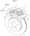
- FIG. 1 is a perspective view of a disc brake being a hydraulic brake according to a first embodiment of the disclosure
- FIG. 2 is a sectional view showing a main portion of the disc brake
- FIG. 3 is a sectional view of a pressing device of the disc brake
- FIG. 4 is an exploded perspective view of a main portion of the disc brake
- FIG. 5 is a sectional view taken along line V-V of FIG. 2 ;
- FIG. 6 is a sectional view taken along line VI-VI of FIG. 2 ;
- FIG. 7 is a perspective view showing a frame of the pressing device
- FIG. 8 is a perspective view showing a spring being a component of the disc brake
- FIG. 9 is a perspective view showing another spring being a component of the disc brake.
- FIG. 10 is a perspective view showing still another spring being a component of the disc brake
- FIG. 11 is a diagram schematically showing the operation of the disc brake
- FIG. 12 is a diagram showing an operating state of the disc brake
- FIG. 13 is a sectional view taken along line XIII-XIII of FIG. 2 ;
- FIG. 14 is a diagram conceptually showing a hydraulic brake system including the hydraulic brake
- FIG. 15 is a flowchart showing a leakage detection program stored in a storage unit of a brake ECU of the hydraulic brake system.
- FIG. 16 is a sectional view of a disc brake being a hydraulic brake according to a second embodiment of the disclosure.
- a disc brake 2 according to this embodiment is of the floating type and is a hydraulic disc brake that is operated by the hydraulic pressure.
- Disc brakes 2 are components of a hydraulic brake system shown in FIG. 14 and are respectively attached to right and left front wheels.
- the floating-type hydraulic disc brake 2 includes (I) an inner pad 4 and an outer pad 6 that are located on both sides of a rotor 3 so as to sandwich therebetween the rotor 3 that is rotated together with the wheel, (II) a pressing device 8 , and (III) a housing 10 supporting the pressing device 8 .
- the pressing device 8 includes a wheel cylinder 14 and a frame 16 .
- the wheel cylinder 14 includes a first piston 24 as a first pressing member and a second piston 26 as a second pressing member that are liquid-tightly and slidably fitted in a cylinder bore 21 formed in a main housing portion 28 of the housing 10 .
- a hydraulic pressure chamber 30 is defined between the first piston 24 and the second piston 26 in the cylinder bore 21 .
- Piston seals 24 s , 26 s are respectively provided between the first piston 24 and the cylinder bore 21 and between the second piston 26 and the cylinder bore 21 , and therefore, strictly speaking, the hydraulic pressure chamber 30 is defined as a portion surrounded by the piston seals 24 s , 26 s and the cylinder bore 21 .
- a portion, formed with the cylinder bore 21 , of the main housing portion 28 is a cylinder body 14 h being the body of the wheel cylinder 14 so that the wheel cylinder 14 is held by the main housing portion 28 .
- the frame 16 is a frame-shaped rigid body and is held by the main housing portion 28 so as to be relatively movable in the direction parallel to the rotation axis L of the rotor 3 .
- the rotation axis L of the rotor 3 is parallel to the axis M of the pressing device 8 , and therefore, hereinafter, the direction parallel to the rotation axis L of the rotor 3 may be referred to as the axial direction of the pressing device 8 or simply as the axial direction, or as the direction parallel to the axis M.
- the side where the main housing portion 28 is located is the vehicle inner side
- the side where the outer pad 6 is located is the vehicle outer side.
- the disc brake 2 is operated when the hydraulic pressure is supplied to the hydraulic pressure chamber 30 of the wheel cylinder 14 .
- the first piston 24 is moved parallel to the axis M toward the rotor 3
- the second piston 26 is moved parallel to the axis M in the direction away from the rotor 3 .
- the first piston 24 presses the inner pad 4 against the rotor 3
- the second piston 26 moves the frame 16 in the direction of arrow X.
- the outer pad 6 is pressed against the rotor 3 .
- the rotor 3 is pressed by the inner pad 4 and the outer pad 6 from its both sides so that the disc brake 2 is in the operating state. Details will be described below.
- the inner pad 4 and the outer pad 6 respectively include back plates 4 r , 6 r and friction engagement members 4 f , 6 f.
- the housing 10 includes (a) the main housing portion 28 , (b) a bridge portion 32 extending from the main housing portion 28 across the rotor 3 , (c) a pair of pad pins 34 , 35 spaced apart from each other in the circumferential direction of the rotor 3 , and so on.
- the main housing portion 28 extends generally in the axial direction, and the cylinder bore 21 is formed in the main housing portion 28 so as to pass through the main housing portion 28 in the direction parallel to the axis M.
- the first piston 24 and the second piston 26 each have a bottomed hollow cylindrical shape and are concentrically fitted in the cylinder bore 21 in tandem in the axial direction in a posture in which the bottoms of the first and second pistons 24 , 26 face the hydraulic pressure chamber 30 .
- the main housing portion 28 is provided with a pair of to-be-attached portions 36 , 37 .
- the to-be-attached portions 36 , 37 are respectively provided on both sides, in the direction perpendicular to the axis M, of an end portion of the main housing portion 28 on the side close to the rotor 3 in the axial direction.
- the to-be-attached portions 36 , 37 extend radially inward of the rotor 3 and are attached to a suspension member being a non-rotary member such as a knuckle (which can also be referred to as a vehicle body side member).
- the main housing portion 28 is provided with two pairs of to-be-engaged portions that are engageable with the frame 16 .
- the two pairs of to-be-engaged portions are respectively provided at both end portions of the main housing portion 28 in the axial direction. Specifically, as shown in FIGS.
- first engagement recess portions 40 , 41 being the pair of to-be-engaged portions of the two pairs of to-be-engaged portions are respectively provided on both sides, in the direction perpendicular to the axis M, of the end portion of the main housing portion 28 on the side close to the rotor 3 in the axial direction
- second engagement recess portions 42 , 43 being the other pair of to-be-engaged portions are respectively provided on both sides, in the direction perpendicular to the axis M, of the end portion of the main housing portion 28 on the side remote from the rotor 3 in the axial direction.
- the first engagement recess portions 40 , 41 are respectively provided to the to-be-attached portions 36 , 37 .
- the radial center points of the first engagement recess portions 40 , 41 and the second engagement recess portions 42 , 43 are located approximately on a center reference plane S.
- the center reference plane S is a plane that is perpendicular to a reference line P being a line perpendicular to the rotation axis L of the rotor 3 and to a center line passing through the center of the first piston 24 and the center of the second piston 26 (being the same as the axis M) and that includes the axis M.
- the first engagement recess portions 40 , 41 and the second engagement recess portions 42 , 43 each have a groove extending in the axial direction.
- the first engagement recess portion 41 has a pair of wall surfaces 41 a , 41 b spaced apart from each other in the radial direction of the rotor 3 (hereinafter may be simply referred to as the radial direction) and a bottom surface 41 c located between the wall surfaces 41 a , 41 b .
- the wall surfaces 41 a , 41 b each extend parallel to the center reference plane S.
- the first engagement recess portion 40 and the second engagement recess portions 42 , 43 each have a pair of wall surfaces and a bottom surface.
- the bridge portion 32 has a generally U-shape in plan view and has a first end portion fixed to one of the to-be-attached portions 36 , 37 and a second end portion fixed to the other of the to-be-attached portions 36 , 37 .
- the bridge portion 32 includes a first rod 50 extending in the axial direction, a second rod 52 extending parallel to the first rod 50 and spaced apart from the first rod 50 in the circumferential direction of the rotor 3 , and a connecting portion 54 connecting the first rod 50 and the second rod 52 together on the opposite side of the rotor 3 from the main housing portion 28 .
- the connecting portion 54 extends in the direction perpendicular to the axis M in plan view and may have an arbitrary shape.
- Through-holes 56 , 58 each extending in the axial direction are respectively formed at both end portions of the connecting portion 54 in the circumferential direction of the rotor 3 .
- through-holes 60 , 62 each extending in the axial direction are respectively formed at portions of the main housing portion 28 corresponding to the through-holes 56 , 58 .
- the pad pins 34 , 35 each extend in the axial direction and are respectively provided with heads 34 h , 35 h at first end portions thereof.
- the pad pins 34 , 35 respectively pass through the through-holes 60 , 62 , through-holes formed in the back plates 4 r , 6 r of the inner pad 4 and the outer pad 6 , and the through-holes 56 , 58 in this order.
- the pad pins 34 , 35 are held by the main housing portion 28 at the first end portions thereof and by the bridge portion 32 at second end portions thereof, and thus are held by the housing 10 at both first and second end portions thereof.
- the heads 34 h , 35 h of the pad pins 34 , 35 are located on the vehicle inner side of the through-holes 60 , 62 of the main housing portion 28 , and split pins (not shown) are respectively attached to the pad pins 34 , 35 at portions on the opposite side (rotor side) of the through-holes 60 , 62 , thereby preventing coming-off of the pad pins 34 , 35 . Since the heads 34 h , 35 h are located on the vehicle inner side of the rotor 3 , the pad pins 34 , 35 are prevented from coming off to the vehicle outer side.
- the inner pad 4 and the outer pad 6 are held to be movable in the axial direction by the pad pins 34 , 35 , but since the pad pins 34 , 35 are provided so as to be spaced apart from each other in the circumferential direction, turning of the inner pad 4 and the outer pad 6 around the pad pins 34 , 35 is suppressed.
- a pad spring 70 in the form of a leaf spring is attached to intermediate portions of the pad pins 34 , 35 at portions radially outward of the friction engagement members 4 f , 6 f .
- the pad spring 70 applies elastic forces to the inner pad 4 and the outer pad 6 in the radial and circumferential directions and applies elastic forces to the pad pins 34 , 35 in the direction toward each other.
- the pad spring 70 the backlash of the inner pad 4 and the outer pad 6 is suppressed so that the occurrence of vibration and noise is suppressed.
- the cylinder body 14 h is provided with a fragile portion 71 .
- the fragile portion 71 is provided at a portion Ra, shown in FIG. 2 , of an intermediate portion of the cylinder body 14 h , i.e. at “a portion that remains after portions where the first piston 24 and the second piston 26 slide are removed from a portion, corresponding to the hydraulic pressure chamber 30 , of the cylinder body 14 h ”. That is, in the portion, corresponding to the hydraulic pressure chamber 30 , of the cylinder body 14 h , the portion Ra is a portion between a bottom surface 24 f of the first piston 24 and a bottom surface 26 f of the second piston 26 in the non-operating state of the wheel cylinder 14 . As shown in FIG.
- the fragile portion 71 includes an arc-shaped recess 72 formed at an intermediate portion of a side portion of the main housing portion 28 , and an arc-shaped cut-out recess 73 further formed at a middle portion, in the axial direction, of the recess 72 .
- the fragile portion 71 is provided at the portion Ra, i.e. even when the recess 72 is formed so as to be open at “the portion that remains after the portions where the first piston 24 and the second piston 26 slide are removed from the portion, corresponding to the hydraulic pressure chamber 30 of the cylinder bore 21 , of the cylinder body 14 h ”, there is no influence on sliding of the first piston 24 and the second piston 26 .
- the frame 16 is a generally frame-shaped rigid body and includes (i) a first side portion 74 and a second side portion 75 each extending in the direction perpendicular to the axis M and spaced apart from each other in the axial direction, and (ii) a third side portion 77 and a fourth side portion 78 each extending in the direction perpendicular to the first side portion 74 and the second side portion 75 and spaced apart from each other in the direction perpendicular to the axis M.
- the third side portion 77 and the fourth side portion 78 each connect the first side portion 74 and the second side portion 75 together.
- the first side portion 74 and the second side portion 75 are located on the opposite sides of the rotor 3 in the axial direction.
- the first side portion 74 is located on the vehicle outer side of the rotor 3 and faces the outer pad 6 .
- the second side portion 75 is located on the vehicle inner side of the rotor 3 and engaged with the second piston 26 .
- the third side portion 77 and the fourth side portion 78 are each provided to extend to the vehicle inner side and to the vehicle outer side of the rotor 3 . As shown in FIGS. 5 and 6 , the third side portion 77 and the fourth side portion 78 are provided across the rotor 3 without being located radially outward of the inner pad 4 and the outer pad 6 . In other words, as shown in FIGS.
- the third side portion 77 and the fourth side portion 78 are bent such that the interval between portions 77 a , 78 a located radially outward of the rotor 3 is greater than the interval between portions 77 b , 78 b located on the vehicle inner side of the rotor 3 (hereinafter, the portions 77 b , 78 b may be referred to as the inner side portions 77 b , 78 b ).
- the inner pad 4 and the outer pad 6 are located between the interval-greater portions 77 a , 78 a.
- Two pairs of engagement portions are provided on side surfaces, facing each other, of the inner side portions 77 b , 78 b of the third side portion 77 and the fourth side portion 78 so as to be spaced apart from each other in the axial direction.
- First engagement projecting portions 80 , 82 being the pair of engagement portions of the two pairs of engagement portions are respectively located at rotor-side end portions of the inner side portions 77 b , 78 b
- second engagement projecting portions 81 , 83 being the other pair of engagement portions are respectively located at end portions of the inner side portions 77 b , 78 b on the side remote from the rotor 3 .
- the first engagement projecting portions 80 , 82 and the second engagement projecting portions 81 , 83 have shapes that are respectively engageable with the first engagement recess portions 40 , 41 and the second engagement recess portions 42 , 43 .
- the radial center points of the first engagement projecting portions 80 , 82 and the second engagement projecting portions 81 , 83 are located approximately on the center reference plane S.
- the first engagement projecting portions 80 , 82 each include two projecting portions spaced apart from each other with a gap therebetween in the axial direction. Specifically, the first engagement projecting portion 80 includes two projecting portions 80 a , 80 b , and the first engagement projecting portion 82 includes two projecting portions 82 a , 82 b .
- the first engagement projecting portions 80 ( 80 a , 80 b ), 82 ( 82 a , 82 b ) and the second engagement projecting portions 81 , 83 each have a generally rectangular parallelepiped shape protruding in the direction perpendicular to the axis M and each have a pair of side surfaces radially spaced apart from each other and parallel to the center reference plane S, a top surface located between the side surfaces, and so on.
- the projecting portion 80 a of the first engagement projecting portion 80 has side surfaces 80 ap , 80 aq , and a top surface 80 at .
- This also applies to the first engagement projecting portion 82 and the second engagement projecting portions 81 , 83 i.e. each having a pair of side surfaces parallel to the center reference plane S and a top surface.
- the first engagement projecting portions 80 , 82 of the frame 16 are respectively engaged with the first engagement recess portions 40 , 41 of the main housing portion 28
- the second engagement projecting portions 81 , 83 are respectively engaged with the second engagement recess portions 42 , 43 , so that the frame 16 is held by the main housing portion 28 .
- the radial center points of the first engagement projecting portions 80 , 82 and the second engagement projecting portions 81 , 83 and the radial center points of the first engagement recess portions 40 , 41 and the second engagement recess portions 42 , 43 are located on the center reference plane S. Therefore, the frame 16 is held by the main housing portion 28 on the plane that is the same as the center reference plane S.
- the radial center points of holding portions, holding the frame 16 , of the main housing portion 28 are located on the center reference plane S.
- the holding portion represents a portion where the engagement projecting portion and the engagement recess portion are engaged together.
- the first engagement projecting portions 80 , 82 and the second engagement projecting portions 81 , 83 each have a pair of side surfaces extending parallel to the center reference plane S
- the first engagement recess portions 40 , 41 and the second engagement recess portions 42 , 43 each have a pair of wall surfaces extending parallel to the center reference plane S, wherein these side surfaces and wall surfaces, i.e. the surfaces, are engageable with each other.
- a leaf spring as an elastic member is provided between each of the first engagement projecting portions 80 , 82 and the second engagement projecting portions 81 , 83 and a corresponding one of the first engagement recess portions 40 , 41 and the second engagement recess portions 42 , 43 .
- radial springs 86 are respectively attached to the projecting portion 80 a of the first engagement projecting portion 80 and the projecting portion 82 a of the first engagement projecting portion 82
- circumferential springs 88 are respectively attached to the projecting portion 80 b and the projecting portion 82 b
- radial springs 94 are respectively attached to the second engagement projecting portions 81 , 83 .
- the radial spring 86 is formed by bending an elongated plate member 90 and includes a fitting portion 86 a bent in a generally ]-shape and a spring portion 86 b formed so as to be placed over a side surface of the fitting portion 86 a with a gap therebetween. Further, an end portion of the spring portion 86 b is partially bent with respect to the axial direction to provide an inclined portion 86 c . For example, as shown in FIG.
- the radial spring 86 is attached to the projecting portion 80 a in the state where the projecting portion 80 a is fitted in the fitting portion 86 a in the radial direction and the spring portion 86 b is located radially inward of the side surface 80 aq of the projecting portion 80 a . Since the radial spring 94 has the same shape as the radial spring 86 , a description thereof will be omitted.
- the circumferential spring 88 is likewise formed by bending an elongated plate member 92 and includes a fitting portion 88 a and a spring portion 88 b formed so as to be placed over a bottom surface of the fitting portion 88 a with a gap therebetween.
- the circumferential spring 88 is attached to the projecting portion 80 b in the state where the projecting portion 80 b is fitted in the fitting portion 88 a in the axial direction and the spring portion 88 b is located circumferentially inward of the top surface 80 bt of the projecting portion 80 b.
- the first engagement projecting portion 80 is engaged with the first engagement recess portion 40 such that the spring portion 86 b of the radial spring 86 is located between the side surface 80 aq of the projecting portion 80 a and the wall surface 40 b of the first engagement recess portion 40 and that the spring portion 88 b of the circumferential spring 88 is located between the top surface 80 bt of the projecting portion 80 b and the bottom surface 40 c of the first engagement recess portion 40 .
- the radial springs 86 , 94 and the circumferential springs 88 between the main housing portion 28 and the frame 16 , the positional deviation of the frame 16 relative to the main housing portion 28 in the radial and circumferential directions is absorbed.
- the positioning of the frame 16 can be achieved so that it is possible to reliably move the frame 16 in the axial direction.
- radial and circumferential external forces that act between the frame 16 and the main housing portion 28 are absorbed by the radial springs 86 , 94 and the circumferential springs 88 , it is possible to suppress the occurrence of vibration and noise of the frame 16 . Further, it is possible to improve the ease of assembly of the frame 16 to the main housing portion 28 . Further, the insertion of the projecting portion 80 a into the first engagement recess portion 40 is facilitated by the inclined portion 86 c.
- the frame 16 is designed such that, in side view, the center of gravity G is located between the holding portions, holding the frame 16 , of the main housing portion 28 (range K), i.e. between an end face of the first engagement projecting portion 80 , 82 on the vehicle outer side and an end face of the second engagement projecting portion 81 , 83 on the vehicle inner side. Even when the frame 16 is moved in the axial direction, the center of gravity G does not deviate from the range K. When the inner pad 4 and the outer pad 6 are worn out, the position of the frame 16 relative to the main housing portion 28 in the non-operating state of the disc brake 2 is moved to the vehicle inner side. Therefore, even when the inner pad 4 and the outer pad 6 are worn out, the center of gravity G of the frame 16 is located in the range K.
- a projecting portion 100 protruding in the axial direction is provided on a surface, facing the second piston 26 , of the second side portion 75 .
- the projecting portion 100 has a shape defined by a curved surface, i.e. a round shape, in the circumferential direction and is attached with a coupling spring 102 as an elastic member.
- the coupling spring 102 is a leaf spring and is formed by bending a plate member 104 .
- the coupling spring 102 includes a fitting portion 102 a bent in a generally]-shape and a spring portion 102 b formed so as to be placed over a side surface of the fitting portion 102 a with an interval therebetween. Since the interval of the plate member 104 in the spring portion 102 b is large, the spring force of the coupling spring 102 is small.
- the coupling spring 102 is attached to the projecting portion 100 in the state where the projecting portion 100 is fitted in the fitting portion 102 a in the radial direction and the spring portion 102 b is located radially outward of the projecting portion 100 .
- the projecting portion 100 is engaged with a hollow cylindrical portion 106 of the second piston 26 such that the spring portion 102 b of the coupling spring 102 is located between the projecting portion 100 and an inner peripheral surface 106 f of the hollow cylindrical portion 106 of the second piston 26 .
- the frame 16 can be moved in the direction of arrow Y in FIG. 11 along with the movement of the second piston 26 to return to the initial position (the position when the disc brake 2 is in the non-operating state), so that it is possible to quickly separate the outer pad 6 from the rotor 3 and thus suppress dragging of the outer pad 6 .
- the projecting portion 100 has the round shape in the circumferential direction, it is suppressed that the frame 16 is difficult to turn in the operation of the disc brake 2 due to the engagement with the second piston 26 via the coupling spring 102 .
- the spring force of the coupling spring 102 is small, pinching or the like of the second piston 26 is reliably avoided. Rubber or the like may be provided as an elastic member instead of the coupling spring 102 .
- the ratio (H/D) of a thickness (length in the radial direction) H of each of the first side portion 74 and the second side portion 75 of the frame 16 to a diameter D of the cylinder bore 21 of the main housing portion 28 is set to about 0.33. Since the ratio of the thickness of each of the first side portion 74 and the second side portion 75 to the diameter of the cylinder bore 21 is set to the relatively large value, the disc brake 2 can be reliably operated so that it is possible to improve the reliability.
- the ratio (H/D) is satisfactory if it is 0.17 or more, and is preferably 0.2 or more.
- the frame 16 may be made of, for example, carbon fiber reinforced plastic (CFRP). Since the wheel cylinder 14 is formed in the main housing portion 28 , high machining accuracy is not required for the frame 16 . Therefore, when manufacturing the frame 16 , the need for machining such as cutting or grinding becomes low so that, for example, the frame 16 can be manufactured by press working. The press working is suitable for processing the carbon fiber reinforced plastic.
- CFRP carbon fiber reinforced plastic
- the carbon fiber reinforced plastic is poor in durability, but is light in weight. As a result, the travel distance relative to the power can be increased.
- a portion of the frame 16 that is adjacent to the outer pad 6 in the circumferential direction serves as a torque receiving portion, while the resin has high damping characteristics. Therefore, it is possible to suppress vibration and thus reduce noise in the operating state of the disc brake 2 .
- the third side portion 77 and the fourth side portion 78 are desirable to manufacture such that the direction of carbon fibers coincides with the axial direction, i.e. the orientation of carbon fibers becomes high in the axial direction. Consequently, the strength against forces that act on the frame 16 in the axial direction can be made large so that it is possible to reliably suppress deformation of the frame 16 due to forces F, R.
- pressurizing chambers 154 , 156 of a master cylinder 152 are connected to the hydraulic pressure chambers 30 of the wheel cylinders 14 of the disc brakes 2 via a hydraulic pressure control unit 150 .
- the master cylinder 152 includes two pressurizing pistons, and the pressurizing chambers 154 , 156 are respectively provided in front of the pressurizing pistons.
- a brake pedal 160 as a brake operating member is linked to one of the two pressurizing pistons so that the hydraulic pressures are generated in the pressurizing chambers 154 , 156 by the operation of the brake pedal 160 .
- a reservoir tank 162 is connected to the master cylinder 152 .
- the pressurizing pistons When the pressurizing pistons are located at the retreat end positions, communication is established between the pressurizing chambers 154 , 156 and the reservoir tank 162 .
- the working fluid returned from the hydraulic pressure chambers 30 of the wheel cylinders 14 to the pressurizing chambers 154 , 156 is returned to the reservoir tank 162 .
- Master shut-off valves 164 , 166 are provided between the pressurizing chambers 154 , 156 and the hydraulic pressure control unit 150 . In the closed state of the master shut-off valves 164 , 166 , the hydraulic pressures in the hydraulic pressure chambers 30 of the wheel cylinders 14 are controlled by the hydraulic pressure control unit 150 .
- the hydraulic pressure control unit 150 may include, for example, a pump and a control valve device including one or more solenoid control valves.
- the reservoir tank 162 is connected to the hydraulic pressure control unit 150 , and the pump draws up the working fluid from the reservoir tank 162 , and pressurizes and discharges it.
- the control valve device returns the working fluid from the wheel cylinders 14 to the reservoir tank 162 so as to reduce the hydraulic pressures in the wheel cylinders 14 .
- the hydraulic pressures in the wheel cylinders 14 are controlled by controlling at least one of a pump motor that drives the pump, and the solenoid control valve.
- a brake ECU 170 including a computer as a main component is provided.
- the wheel cylinder pressure sensors 180 , 182 respectively detect the hydraulic pressures in the hydraulic pressure chambers 30 of the wheel cylinders 14 (hereinafter may be referred to as the wheel cylinder pressures).
- the remaining amount sensor 184 detects the reservoir remaining amount being the amount of the working fluid stored in the reservoir tank 162 .
- the stroke sensor 186 detects the stoke of the brake pedal 160 .
- the object detection device 188 detects objects (vehicle, person, stationary object, etc.) that are present around the vehicle.
- the object detection device 188 includes at least one of a camera and a radar and detects objects around the vehicle based on a captured image from the camera, a signal from the radar, and so on.
- the notification device 190 includes a display or a sound generation device and notifies a state of the hydraulic brake system, or the like.
- the disc brakes 2 are operated.
- the disc brakes 2 are each provided with the fragile portion 71 , when the number of times of operation of the disc brake 2 is increased, the fragile portion 71 tends to be damaged so that the leakage of the working fluid tends to occur.
- the leakage amount due to damage of the cut-out recess 73 is small.
- the fragile portion 71 is designed such that durability of the fragile portion 71 is the poorest in the disc brake 2 , it is expected that at the time when the fragile portion 71 is damaged to cause the leakage, the other portion of the disc brake 2 is not damaged. In other words, even when the fragile portion 71 is damaged to cause the leakage, the disc brake 2 is still operable and is capable of suppressing the rotation of the wheel.
- the time when the leakage has occurred in the fragile portion 71 is the time when it is desirable to perform maintenance of the disc brake 2 or replace at least part of the disc brake 2 .
- the durability of the fragile portion 71 i.e., for example, as shown in FIG. 13 , a thickness t of the main housing portion 28 at the fragile portion 71 and a central angle 2 ⁇ corresponding to the length of an arc of the recess 72 , 73 , is designed such that the leakage in the fragile portion 71 serves as an indicator that it is desirable to perform maintenance of the disc brake 2 or replace at least part (e.g. the frame 16 ) of the disc brake 2 .
- the presence or absence of the leakage in the fragile portion 71 is detected by execution of a leakage presence/absence detection program in the brake ECU 170 and notified.
- the leakage presence/absence detection program is represented by a flowchart of FIG. 15 and executed at every predetermined set time.
- step 1 hereinafter abbreviated as S 1 ; the same applies to the other steps
- the presence or absence of the leakage is detected, and at S 2 , it is determined whether or not the detection result is “the leakage is present”.
- a determination at S 2 becomes YES so that the notification device 190 is operated at S 3 .
- the presence or absence of the leakage can be detected, for example, by the following method. Detection of the presence or absence of the leakage is performed on the assumption that the other portion of the hydraulic brake system is normal.
- the set amount can be set to, for example, an amount that is necessarily stored in the reservoir tank 162 when there is no leakage.
- the set amount can be changed between when the reservoir remaining amount is detected in the non-operating state of the disc brake 2 and when it is detected in the operating state of the disc brake 2 .
- the detected wheel cylinder pressure when the wheel cylinder pressure detected by the wheel cylinder pressure sensor 180 , 182 (hereinafter referred to as the detected wheel cylinder pressure) is less than a wheel cylinder pressure, determined based on the relationship and the stroke of the brake pedal 160 measured by the stroke sensor 186 , by a set pressure or more, the leakage is detected to be present in the corresponding wheel cylinder 14 .
- a target hydraulic pressure is acquired based on the operating state of the brake pedal 160 , the relative positional relationship between an object around the vehicle detected by the object detection device 188 and the vehicle (the subject vehicle, i.e. the own vehicle), or the like, and the hydraulic pressure control unit 150 is controlled based on the target hydraulic pressure.
- the detected wheel cylinder pressure and the target hydraulic pressure should be approximately equal to each other by the control of the hydraulic pressure control unit 150 . Consequently, it can be configured that when the detected wheel cylinder pressure is less than the target hydraulic pressure by a set pressure or more, the leakage is detected to be present in the corresponding wheel cylinder 14 .
- the frame 16 can be manufactured using the carbon fiber reinforced plastic so that it is possible to reduce the weight thereof. Further, it is also possible to reduce the weight of other portions of the disc brake 2 within a range where durability thereof is higher than that of the fragile portion 71 .
- the lines of action of the forces F, R are located in the same plane (in this embodiment, in the center reference plane S). Therefore, it is possible to suppress the inclination of the frame 16 in the operation of the disc brake 2 . Further, since the lines of action of the forces F, R and the center points of the holding portions, holding the frame 16 , of the main housing portion 28 are located on the same plane, it is possible to suppress deformation of the frame 16 in the operating state of the disc brake 2 and thus suppress a reduction in pressing force that is otherwise caused by such deformation of the frame 16 .
- the pad pins 34 , 35 are each held by the housing 10 at both end portions thereof. Therefore, the postures of the inner pad 4 and the outer pad 6 can be stably held, and it is possible to reliably suppress radially inward sliding-down of the outer pad 6 .
- the pad pins 34 , 35 are attached to the housing 10 without using screw fastening. As a result, it is possible to reduce the processing cost and improve the workability. Since the screw fastening is not used, it is easy to detach the pad pins 34 , 35 so that the work of replacing the inner pad 4 and the outer pad 6 is facilitated.
- the length of the recess 72 and the cut-out recess 73 does not matter.
- the recess 72 and the cut-out recess 73 can be provided in an annular shape.
- the fragile portion 71 can be provided at “any portion, corresponding to the hydraulic pressure chamber 30 , of the intermediate portion of the cylinder body 14 h ”, i.e. not limited to “a portion that remains after portions where the first piston 24 and the second piston 26 slide are removed from a portion, corresponding to the hydraulic pressure chamber 30 , of the cylinder body 14 h ”.
- the fragile portion 71 can be provided at “one of the portions, where the first piston 24 and the second piston 26 slide, in the portion, corresponding to the hydraulic pressure chamber 30 , of the cylinder body 14 h ”, for example, at “a portion of the cylinder body 14 h , corresponding to one of portions between the bottom surfaces 24 f , 26 f of the first and second pistons 24 , 26 and the piston seals 24 s , 26 s in the non-operating state of the wheel cylinder 14 ”.
- the fragile portion 71 can be provided in the cylinder body 14 h at a portion including portions facing the round portions 24 r , 26 r of the first piston 24 and the second piston 26 . This is because even when the opening of the recess 72 is located at the portions, facing the round portions 24 r , 26 r , of the cylinder bore 21 of the cylinder body 14 h , the influence on sliding of the first piston 24 and the second piston 26 is small.
- the presence or absence of the leakage can be detected using various other methods, i.e. not limited to the method in this embodiment.
- a hydraulic brake according to the disclosure can be applied to a disc brake 200 shown in FIG. 16 .
- the hydraulic disc brake 200 includes (I) an inner pad 204 and an outer pad 206 that are located on both sides of a rotor 202 so as to sandwich the rotor 202 therebetween, (II) a caliper 210 held by a non-rotary member (not shown) so as to be movable in the axial direction, and so on.
- the caliper 210 is provided across the rotor 202 , the inner pad 204 , and the outer pad 206 .
- a portion located on the vehicle inner side serves as a cylinder body 210 h formed with a bottomed cylinder bore 212
- a portion located on the vehicle outer side serves as a lug portion 210 a.
- a piston 214 is liquid-tightly and slidably fitted in the cylinder bore 212 via a piston seal 216 .
- a portion between a bottom surface 210 f of a bottom portion of the cylinder body 210 h of the caliper 210 and the piston seal 216 serves as a hydraulic pressure chamber 218 .
- a wheel cylinder 220 is formed by the cylinder body 210 h , the piston 214 , the hydraulic pressure chamber 218 , and so on.
- the lug portion 210 a is located outward of the outer pad 206 .
- the caliper 210 is moved in the direction parallel to the rotation axis L of the rotor 202 by the hydraulic pressure in the hydraulic pressure chamber 218 so that the lug portion 210 a presses the outer pad 206 against the rotor 202 .
- a fragile portion 228 is provided on the bottom surface 210 f of the cylinder body 210 h .
- the fragile portion 228 includes a recess 230 extending generally in the diameter direction and a cut-out recess 232 formed at a middle portion of the recess 230 in the direction crossing the recess 230 .
- the bottom surface 210 f corresponds to a portion that remains after a sliding portion of the piston 214 is removed from a portion, corresponding to the hydraulic pressure chamber 218 , of an inner peripheral surface of the cylinder body 210 h.
- the cylinder body 210 h is provided with the fragile portion 228 .
- the fragile portion 228 is damaged to cause the leakage, this is notified.
- the maintenance of the disc brake 200 is performed or at least part (e.g. the caliper 210 ) of the disc brake 200 is replaced, it is possible to prevent damage to the lug portion 210 a .
- the recess 230 of the fragile portion 228 may have a generally circular shape.
- a hydraulic brake including: an inner pad and an outer pad located to sandwich therebetween a rotor configured to rotate with a wheel; a wheel cylinder including a cylinder body formed with a cylinder bore, a hydraulic pressure chamber formed in the cylinder body, and a piston liquid-tightly and slidably fitted in the cylinder bore and configured to be moved by a hydraulic pressure in the hydraulic pressure chamber so as to press the inner pad against the rotor; and a drive member configured to be moved in a direction opposite to the piston by the hydraulic pressure in the hydraulic pressure chamber so as to press the outer pad against the rotor, wherein a fragile portion is provided at a portion, corresponding to the hydraulic pressure chamber, of the cylinder body.
- the fragile portion is a portion where durability is less than that of the other portions. For example, a portion, where the thickness is reduced, of the cylinder body can be the fragile portion.
- the fragile portion is a recessed portion formed in the cylinder body and extending in an arc shape or in a straight line.
- the fragile portion may have a shape extending annularly or may have a circular shape, a rectangular shape, or the like.
- the shape and size of the fragile portion can be designed in consideration of the thickness of the cylinder body at the fragile portion such that the leakage due to damage to the fragile portion can serve as an indicator of the maintenance time of the hydraulic brake or the replacement time of at least part of the hydraulic brake.
- the hydraulic brake includes a housing attached to a non-rotary member and holding the inner pad and the outer pad; the cylinder bore is formed in the housing; the cylinder body is a portion, where the cylinder bore is formed, of the housing; the wheel cylinder further includes a second piston in addition to a first piston being the above-described piston, the second piston liquid-tightly and slidably fitted in the cylinder bore and configured to be moved in the direction opposite to the first piston by the hydraulic pressure in the hydraulic pressure chamber; and the drive member is a frame held by the housing so as to be relatively movable, the frame being a frame-shaped rigid body and configured to be moved in the direction opposite to the first piston by the second piston.
- a hydraulic brake system including: the hydraulic brake according to any one of (1) to (9); a hydraulic pressure supply device connected to the hydraulic pressure chamber; a reservoir tank storing working fluid; a leakage presence/absence detection device configured to detect the presence or absence of leakage of the working fluid in the fragile portion based on at least a state of the hydraulic pressure supply device or a remaining amount of the working fluid stored in the reservoir tank; and a notification device configured to, when the leakage is detected to be present by the leakage presence/absence detection device, notify the detection of the presence of the leakage.
- the hydraulic pressure supply device may be a manual hydraulic pressure generating device (including a brake operating member, a master cylinder, etc.), a power hydraulic pressure source (a pump device that generates hydraulic pressure by power, or the like), a hydraulic pressure control device (a device that generates hydraulic pressure by power and is capable of controlling the hydraulic pressure), or the like.
- a manual hydraulic pressure generating device including a brake operating member, a master cylinder, etc.
- a power hydraulic pressure source a pump device that generates hydraulic pressure by power, or the like
- a hydraulic pressure control device a device that generates hydraulic pressure by power and is capable of controlling the hydraulic pressure
Landscapes
- Engineering & Computer Science (AREA)
- General Engineering & Computer Science (AREA)
- Mechanical Engineering (AREA)
- Braking Arrangements (AREA)
- Valves And Accessory Devices For Braking Systems (AREA)
Abstract
Description
Claims (7)
Applications Claiming Priority (2)
| Application Number | Priority Date | Filing Date | Title |
|---|---|---|---|
| JP2017-235831 | 2017-12-08 | ||
| JP2017235831A JP6950503B2 (en) | 2017-12-08 | 2017-12-08 | Hydraulic braking system |
Publications (2)
| Publication Number | Publication Date |
|---|---|
| US20190178320A1 US20190178320A1 (en) | 2019-06-13 |
| US10816053B2 true US10816053B2 (en) | 2020-10-27 |
Family
ID=66735241
Family Applications (1)
| Application Number | Title | Priority Date | Filing Date |
|---|---|---|---|
| US16/169,539 Expired - Fee Related US10816053B2 (en) | 2017-12-08 | 2018-10-24 | Hydraulic brake |
Country Status (3)
| Country | Link |
|---|---|
| US (1) | US10816053B2 (en) |
| JP (1) | JP6950503B2 (en) |
| CN (1) | CN110017341B (en) |
Cited By (4)
| Publication number | Priority date | Publication date | Assignee | Title |
|---|---|---|---|---|
| US11359683B2 (en) * | 2018-12-17 | 2022-06-14 | Toyota Jidosha Kabushiki Kaisha | Disc-brake apparatus |
| US20220252116A1 (en) * | 2021-02-09 | 2022-08-11 | Toyota Jidosha Kabushiki Kaisha | Disc brake |
| US11549560B2 (en) * | 2020-01-03 | 2023-01-10 | Hl Mando Corporation | Caliper brake |
| US20230204081A1 (en) * | 2021-12-29 | 2023-06-29 | Hyundai Mobis Co., Ltd. | Pad liner for brake apparatus |
Families Citing this family (3)
| Publication number | Priority date | Publication date | Assignee | Title |
|---|---|---|---|---|
| JP7024633B2 (en) | 2018-07-06 | 2022-02-24 | トヨタ自動車株式会社 | Disc brake |
| JP7070168B2 (en) * | 2018-07-06 | 2022-05-18 | トヨタ自動車株式会社 | Disc brake |
| CN117901814B (en) * | 2024-03-15 | 2024-05-24 | 山西承信新能源科技装备有限公司 | Trackless rubber-tyred vehicle based on noise control |
Citations (14)
| Publication number | Priority date | Publication date | Assignee | Title |
|---|---|---|---|---|
| US3428152A (en) * | 1965-11-20 | 1969-02-18 | Girling Ltd | Closed loop disc brake |
| US3493084A (en) * | 1967-06-16 | 1970-02-03 | Ferodo Sa | Closed-loop type disc-brake |
| US3552182A (en) * | 1968-11-20 | 1971-01-05 | Wisconsin Machine Corp | Press brake with hydraulic ram adjustment |
| US3933226A (en) * | 1969-07-11 | 1976-01-20 | Societe Anonyme Francaise Du Ferodo | Disc brake mounting structure |
| US4306639A (en) * | 1980-06-13 | 1981-12-22 | General Motors Corporation | Disc brake caliper with molded flex piston |
| US4570531A (en) * | 1984-02-09 | 1986-02-18 | Allied Corporation | Extensible piston with breakable or displaceable coupler |
| US5168964A (en) * | 1991-04-22 | 1992-12-08 | Nelson Metal Products Corporation | Brake caliper |
| JPH10122272A (en) | 1996-10-17 | 1998-05-12 | Aisin Seiki Co Ltd | Disc brake with sliding cylinder |
| US5887684A (en) * | 1994-08-31 | 1999-03-30 | Itt Manufacturing Enterprises, Inc. | Disk brake calliper |
| US20100170755A1 (en) * | 2009-01-05 | 2010-07-08 | Robert Biggs | Modular brake caliper |
| US20100181151A1 (en) * | 2009-01-22 | 2010-07-22 | Honeywell International Inc. | Hybrid piston bushing sleeve assembly |
| US20110215567A1 (en) * | 2010-03-02 | 2011-09-08 | Magnum Shielding Corporation | Sacrificial hose fitting assembly |
| US20140158488A1 (en) * | 2011-05-09 | 2014-06-12 | Petroceramics S.P.A. | Caliper bodies made from thermoplastic material |
| WO2014091423A2 (en) * | 2012-12-11 | 2014-06-19 | Iorio Franco | Caliper body, particularly for disc brakes |
Family Cites Families (17)
| Publication number | Priority date | Publication date | Assignee | Title |
|---|---|---|---|---|
| JPS5894642A (en) * | 1981-11-30 | 1983-06-04 | Akebono Brake Ind Co Ltd | Pin type disc brake |
| FR2563594B1 (en) * | 1984-04-26 | 1986-07-18 | Dba | SLIDING CALIPER DISC BRAKE |
| JPH0949530A (en) * | 1995-08-04 | 1997-02-18 | Toyota Motor Corp | Spacer for cardan joint and assembling method thereof |
| JP3684882B2 (en) * | 1998-12-10 | 2005-08-17 | トヨタ自動車株式会社 | Brake hydraulic pressure control device |
| JP2009192044A (en) * | 2008-02-18 | 2009-08-27 | Mitsubishi Motors Corp | Motor drive vehicle |
| JP2010175040A (en) * | 2009-01-30 | 2010-08-12 | Hitachi Automotive Systems Ltd | Disc brake |
| JP5464012B2 (en) * | 2010-03-31 | 2014-04-09 | 日立オートモティブシステムズ株式会社 | Disc brake |
| JP2012246983A (en) * | 2011-05-26 | 2012-12-13 | Toyota Motor Corp | Parking brake device |
| JP5715932B2 (en) * | 2011-11-18 | 2015-05-13 | 本田技研工業株式会社 | Disc brake device |
| JP5960290B2 (en) * | 2013-01-08 | 2016-08-02 | ナブテスコ株式会社 | Brake cylinder device and disc brake device |
| JP6052615B2 (en) * | 2013-03-22 | 2016-12-27 | 日信工業株式会社 | Reaction type disc brake |
| JP6308818B2 (en) * | 2014-03-10 | 2018-04-11 | 曙ブレーキ工業株式会社 | Floating disc brake |
| FR3041048B1 (en) * | 2015-09-16 | 2018-08-17 | Chassis Brakes Int Bv | BRAKE CALIPER IN TWO PARTS, BI-MATERIAL DISC BRAKE WITH ELECTRO-HYDRAULIC PARK BRAKE, AND METHOD OF INDUSTRIALIZATION AND ASSEMBLY |
| JP2017078497A (en) * | 2015-10-22 | 2017-04-27 | トヨタ自動車株式会社 | Disc brake device for vehicle |
| CN205278160U (en) * | 2015-11-28 | 2016-06-01 | 重庆华洋单向器制造有限公司 | Liquid buffering isolator |
| JP6674825B2 (en) * | 2016-04-07 | 2020-04-01 | 小倉クラッチ株式会社 | Electromagnetic brake |
| CN105822705A (en) * | 2016-04-27 | 2016-08-03 | 邹燕燕 | Brake system |
-
2017
- 2017-12-08 JP JP2017235831A patent/JP6950503B2/en not_active Expired - Fee Related
-
2018
- 2018-10-24 US US16/169,539 patent/US10816053B2/en not_active Expired - Fee Related
- 2018-11-27 CN CN201811423596.0A patent/CN110017341B/en not_active Expired - Fee Related
Patent Citations (14)
| Publication number | Priority date | Publication date | Assignee | Title |
|---|---|---|---|---|
| US3428152A (en) * | 1965-11-20 | 1969-02-18 | Girling Ltd | Closed loop disc brake |
| US3493084A (en) * | 1967-06-16 | 1970-02-03 | Ferodo Sa | Closed-loop type disc-brake |
| US3552182A (en) * | 1968-11-20 | 1971-01-05 | Wisconsin Machine Corp | Press brake with hydraulic ram adjustment |
| US3933226A (en) * | 1969-07-11 | 1976-01-20 | Societe Anonyme Francaise Du Ferodo | Disc brake mounting structure |
| US4306639A (en) * | 1980-06-13 | 1981-12-22 | General Motors Corporation | Disc brake caliper with molded flex piston |
| US4570531A (en) * | 1984-02-09 | 1986-02-18 | Allied Corporation | Extensible piston with breakable or displaceable coupler |
| US5168964A (en) * | 1991-04-22 | 1992-12-08 | Nelson Metal Products Corporation | Brake caliper |
| US5887684A (en) * | 1994-08-31 | 1999-03-30 | Itt Manufacturing Enterprises, Inc. | Disk brake calliper |
| JPH10122272A (en) | 1996-10-17 | 1998-05-12 | Aisin Seiki Co Ltd | Disc brake with sliding cylinder |
| US20100170755A1 (en) * | 2009-01-05 | 2010-07-08 | Robert Biggs | Modular brake caliper |
| US20100181151A1 (en) * | 2009-01-22 | 2010-07-22 | Honeywell International Inc. | Hybrid piston bushing sleeve assembly |
| US20110215567A1 (en) * | 2010-03-02 | 2011-09-08 | Magnum Shielding Corporation | Sacrificial hose fitting assembly |
| US20140158488A1 (en) * | 2011-05-09 | 2014-06-12 | Petroceramics S.P.A. | Caliper bodies made from thermoplastic material |
| WO2014091423A2 (en) * | 2012-12-11 | 2014-06-19 | Iorio Franco | Caliper body, particularly for disc brakes |
Cited By (5)
| Publication number | Priority date | Publication date | Assignee | Title |
|---|---|---|---|---|
| US11359683B2 (en) * | 2018-12-17 | 2022-06-14 | Toyota Jidosha Kabushiki Kaisha | Disc-brake apparatus |
| US11549560B2 (en) * | 2020-01-03 | 2023-01-10 | Hl Mando Corporation | Caliper brake |
| US20220252116A1 (en) * | 2021-02-09 | 2022-08-11 | Toyota Jidosha Kabushiki Kaisha | Disc brake |
| US20230204081A1 (en) * | 2021-12-29 | 2023-06-29 | Hyundai Mobis Co., Ltd. | Pad liner for brake apparatus |
| US12276311B2 (en) * | 2021-12-29 | 2025-04-15 | Hyundai Mobis Co., Ltd. | Pad liner for brake apparatus |
Also Published As
| Publication number | Publication date |
|---|---|
| JP2019100531A (en) | 2019-06-24 |
| CN110017341A (en) | 2019-07-16 |
| US20190178320A1 (en) | 2019-06-13 |
| CN110017341B (en) | 2021-05-28 |
| JP6950503B2 (en) | 2021-10-13 |
Similar Documents
| Publication | Publication Date | Title |
|---|---|---|
| US10816053B2 (en) | Hydraulic brake | |
| EP2687744B1 (en) | Caliper brake | |
| JP4598098B2 (en) | Gear pump sealing device | |
| US10844916B2 (en) | Brake device | |
| JPWO2018016481A1 (en) | Vehicle weight measuring device | |
| CA2984607C (en) | Axial swage tool | |
| CN100540959C (en) | Sealing means | |
| JP5653475B2 (en) | Piston pump with sealing device | |
| JP2018514439A (en) | Adjustable spring support | |
| US20110162918A1 (en) | Disc brake device | |
| KR102159591B1 (en) | Slip control braking pump having a high pressure sealing structure | |
| GB2537339A (en) | A cylinder with position feedback sensor | |
| JPWO2008047840A1 (en) | Disc caliper brake caliper | |
| US20230406281A1 (en) | Brake system | |
| US8714319B2 (en) | Disk brake | |
| KR101335231B1 (en) | Pneumatic brake booster | |
| CN210290546U (en) | Disc brake | |
| US20200109751A1 (en) | Disc brake | |
| CN105798631A (en) | Rotary table and clamping mechanism | |
| US11078976B2 (en) | Disc brake | |
| CN110345177B (en) | Disc brake and control method | |
| US20210047027A1 (en) | Brake actuator | |
| JP6262961B2 (en) | Sealing device | |
| JP4736706B2 (en) | Master cylinder | |
| CN110230651A (en) | A kind of disk brake |
Legal Events
| Date | Code | Title | Description |
|---|---|---|---|
| AS | Assignment |
Owner name: TOYOTA JIDOSHA KABUSHIKI KAISHA, JAPAN Free format text: ASSIGNMENT OF ASSIGNORS INTEREST;ASSIGNOR:YOKOYAMA, TOMOHIRO;REEL/FRAME:047303/0190 Effective date: 20180903 |
|
| FEPP | Fee payment procedure |
Free format text: ENTITY STATUS SET TO UNDISCOUNTED (ORIGINAL EVENT CODE: BIG.); ENTITY STATUS OF PATENT OWNER: LARGE ENTITY |
|
| STPP | Information on status: patent application and granting procedure in general |
Free format text: DOCKETED NEW CASE - READY FOR EXAMINATION |
|
| STPP | Information on status: patent application and granting procedure in general |
Free format text: NON FINAL ACTION MAILED |
|
| STPP | Information on status: patent application and granting procedure in general |
Free format text: RESPONSE TO NON-FINAL OFFICE ACTION ENTERED AND FORWARDED TO EXAMINER |
|
| STPP | Information on status: patent application and granting procedure in general |
Free format text: NOTICE OF ALLOWANCE MAILED -- APPLICATION RECEIVED IN OFFICE OF PUBLICATIONS |
|
| STCF | Information on status: patent grant |
Free format text: PATENTED CASE |
|
| FEPP | Fee payment procedure |
Free format text: MAINTENANCE FEE REMINDER MAILED (ORIGINAL EVENT CODE: REM.); ENTITY STATUS OF PATENT OWNER: LARGE ENTITY |
|
| LAPS | Lapse for failure to pay maintenance fees |
Free format text: PATENT EXPIRED FOR FAILURE TO PAY MAINTENANCE FEES (ORIGINAL EVENT CODE: EXP.); ENTITY STATUS OF PATENT OWNER: LARGE ENTITY |
|
| STCH | Information on status: patent discontinuation |
Free format text: PATENT EXPIRED DUE TO NONPAYMENT OF MAINTENANCE FEES UNDER 37 CFR 1.362 |
|
| FP | Lapsed due to failure to pay maintenance fee |
Effective date: 20241027 |