US10807179B2 - Method of build-up welding - Google Patents
Method of build-up welding Download PDFInfo
- Publication number
- US10807179B2 US10807179B2 US15/435,932 US201715435932A US10807179B2 US 10807179 B2 US10807179 B2 US 10807179B2 US 201715435932 A US201715435932 A US 201715435932A US 10807179 B2 US10807179 B2 US 10807179B2
- Authority
- US
- United States
- Prior art keywords
- weld
- substrate
- beads
- fill
- welding
- Prior art date
- Legal status (The legal status is an assumption and is not a legal conclusion. Google has not performed a legal analysis and makes no representation as to the accuracy of the status listed.)
- Active, expires
Links
Images


Classifications
-
- B—PERFORMING OPERATIONS; TRANSPORTING
- B23—MACHINE TOOLS; METAL-WORKING NOT OTHERWISE PROVIDED FOR
- B23K—SOLDERING OR UNSOLDERING; WELDING; CLADDING OR PLATING BY SOLDERING OR WELDING; CUTTING BY APPLYING HEAT LOCALLY, e.g. FLAME CUTTING; WORKING BY LASER BEAM
- B23K9/00—Arc welding or cutting
- B23K9/04—Welding for other purposes than joining, e.g. built-up welding
- B23K9/044—Built-up welding on three-dimensional surfaces
-
- B—PERFORMING OPERATIONS; TRANSPORTING
- B23—MACHINE TOOLS; METAL-WORKING NOT OTHERWISE PROVIDED FOR
- B23K—SOLDERING OR UNSOLDERING; WELDING; CLADDING OR PLATING BY SOLDERING OR WELDING; CUTTING BY APPLYING HEAT LOCALLY, e.g. FLAME CUTTING; WORKING BY LASER BEAM
- B23K9/00—Arc welding or cutting
- B23K9/04—Welding for other purposes than joining, e.g. built-up welding
- B23K9/042—Built-up welding on planar surfaces
-
- B—PERFORMING OPERATIONS; TRANSPORTING
- B23—MACHINE TOOLS; METAL-WORKING NOT OTHERWISE PROVIDED FOR
- B23K—SOLDERING OR UNSOLDERING; WELDING; CLADDING OR PLATING BY SOLDERING OR WELDING; CUTTING BY APPLYING HEAT LOCALLY, e.g. FLAME CUTTING; WORKING BY LASER BEAM
- B23K9/00—Arc welding or cutting
- B23K9/16—Arc welding or cutting making use of shielding gas
- B23K9/167—Arc welding or cutting making use of shielding gas and of a non-consumable electrode
-
- B—PERFORMING OPERATIONS; TRANSPORTING
- B23—MACHINE TOOLS; METAL-WORKING NOT OTHERWISE PROVIDED FOR
- B23K—SOLDERING OR UNSOLDERING; WELDING; CLADDING OR PLATING BY SOLDERING OR WELDING; CUTTING BY APPLYING HEAT LOCALLY, e.g. FLAME CUTTING; WORKING BY LASER BEAM
- B23K9/00—Arc welding or cutting
- B23K9/16—Arc welding or cutting making use of shielding gas
- B23K9/173—Arc welding or cutting making use of shielding gas and of a consumable electrode
-
- C—CHEMISTRY; METALLURGY
- C22—METALLURGY; FERROUS OR NON-FERROUS ALLOYS; TREATMENT OF ALLOYS OR NON-FERROUS METALS
- C22C—ALLOYS
- C22C19/00—Alloys based on nickel or cobalt
- C22C19/03—Alloys based on nickel or cobalt based on nickel
- C22C19/05—Alloys based on nickel or cobalt based on nickel with chromium
- C22C19/051—Alloys based on nickel or cobalt based on nickel with chromium and Mo or W
- C22C19/057—Alloys based on nickel or cobalt based on nickel with chromium and Mo or W with the maximum Cr content being less 10%
-
- B—PERFORMING OPERATIONS; TRANSPORTING
- B23—MACHINE TOOLS; METAL-WORKING NOT OTHERWISE PROVIDED FOR
- B23K—SOLDERING OR UNSOLDERING; WELDING; CLADDING OR PLATING BY SOLDERING OR WELDING; CUTTING BY APPLYING HEAT LOCALLY, e.g. FLAME CUTTING; WORKING BY LASER BEAM
- B23K2101/00—Articles made by soldering, welding or cutting
- B23K2101/001—Turbines
-
- B—PERFORMING OPERATIONS; TRANSPORTING
- B23—MACHINE TOOLS; METAL-WORKING NOT OTHERWISE PROVIDED FOR
- B23K—SOLDERING OR UNSOLDERING; WELDING; CLADDING OR PLATING BY SOLDERING OR WELDING; CUTTING BY APPLYING HEAT LOCALLY, e.g. FLAME CUTTING; WORKING BY LASER BEAM
- B23K2103/00—Materials to be soldered, welded or cut
- B23K2103/08—Non-ferrous metals or alloys
-
- B—PERFORMING OPERATIONS; TRANSPORTING
- B23—MACHINE TOOLS; METAL-WORKING NOT OTHERWISE PROVIDED FOR
- B23K—SOLDERING OR UNSOLDERING; WELDING; CLADDING OR PLATING BY SOLDERING OR WELDING; CUTTING BY APPLYING HEAT LOCALLY, e.g. FLAME CUTTING; WORKING BY LASER BEAM
- B23K2103/00—Materials to be soldered, welded or cut
- B23K2103/18—Dissimilar materials
- B23K2103/26—Alloys of Nickel and Cobalt and Chromium
Definitions
- the present embodiments are directed to methods of welding and welded articles. More particularly, the present embodiments are directed to methods of build-up welding with low heat input to the substrate and welded articles without cracks generated during the weld.
- the problem is particularly acute in nickel-based superalloys having a high percentage of the gamma prime ( ⁇ ′) phase. Larger cracks in the weld deposit may be removed by any kind of dilution with various filler materials, but the removal of micro-cracks in the heat-affected zone is not possible by conventional welding processes. In some cases, brazing plus hot isostatic pressing (HIP) may be able to treat such micro-cracks, but brazing plus HIP is more costly than arc welding.
- HIP hot isostatic pressing
- a method of welding includes welding at least one fill bead to fill at least one gap on a substrate by arc scanning with an arc welder.
- the gap is defined by at least one weld bead on the substrate.
- the weld beads are non-overlapping.
- a welded article in another embodiment, includes a substrate including a crack-prone superalloy, at least one weld bead non-overlappingly welded to the substrate, and at least one fill bead.
- Each fill bead is welded to the substrate and to a weld bead or a pair of weld beads to fill at least one gap on the substrate defined by the weld bead or the pair of weld beads.
- the fill bead, weld bead, and a heat-affected zone of the substrate are micro-crack-free and macro-crack-free.
- a method of welding includes welding a plurality of weld beads on a substrate and welding a plurality of fill beads on the substrate with an arc welder while arc scanning.
- the weld beads are non-overlapping.
- the weld beads define gaps formed between neighboring pairs of weld beads.
- the fill beads are welded to the substrate and to the weld beads on the substrate to fill the gaps.
- the fill beads are welded in a non-sequential order.
- FIG. 1 is a schematic side view in a plane perpendicular to the weld direction of a welded article substrate with three weld beads in an embodiment of the present disclosure.
- FIG. 2 is the schematic side view of the welded article of FIG. 1 with a fill bead between two of the weld beads.
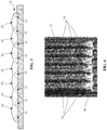
- FIG. 3 is a schematic side view of a portion of a completed welded article in an embodiment of the present disclosure.
- FIG. 4 is a top view of the welded article of FIG. 3 of alternating weld beads and fill beads forming the weld area on the substrate.
- FIG. 5 is a schematic top view of a welded article with a spiral weld bead.
- FIG. 6 is a schematic perspective view of a welded article with a corkscrew weld bead.
- arc scanning and build-up welds including one or more fill beads welded to a substrate and to one or more weld beads in a welded article.
- Embodiments of the present disclosure for example, in comparison to concepts failing to include one or more of the features disclosed herein, produce less of a heat-affected zone (HAZ), provide a more uniform heat input, produce less heat input to the substrate, provide a smaller fusion depth, produce less heat concentration in the substrate and the weld, produce a micro-crack-free build-up weld, produce a macro-crack-free build-up weld, produce a crack-free build-up weld, permit repair of mismachined parts from small to large by build-up weld, permit repair of worn parts from small to large by build-up weld, or combinations thereof.
- HZ heat-affected zone
- a set of weld beads 12 is non-overlappingly welded to a substrate 10 so that there are gaps 14 between the weld beads 12 .
- the weld beads 12 are preferably uniform or substantially uniform in shape along the length of the weld bead 12 .
- the weld beads 12 are preferably applied to the substrate 10 with a predetermined weld bead spacing between each pair of neighboring weld beads 12 such that the gaps 14 formed between the weld beads 12 are channels of a substantially uniform width.
- a fill bead 16 is deposited in each gap 14 between neighboring weld beads 12 .
- the fill bead 16 is preferably applied to the gap 14 with arc scanning to distribute heat from the arc laterally with respect to the weld direction along the surface of the gap 14 including the surface contour 20 of the first weld bead 12 , the exposed surface of the substrate 10 between the gap 14 and the neighboring weld bead 12 , and the surface contour 22 of the neighboring weld bead 12 .
- Each fill bead 16 is preferably welded to the substrate 10 and the neighboring weld beads 12 with complete fusion, without overlapping of neighboring weld beads 12 , and without overlapping of neighboring fill beads 16 .
- a weld area 18 is built up by filling all of the gaps 14 between weld beads 12 on the substrate 10 with fill beads 16 .
- the height of the fill beads 16 may be greater than, less than, or equal to the height of the weld beads 12 .
- the weld beads 12 extend past where the fill beads 16 terminate and so are visible at the bottom of the image.
- the weld is a build-up weld.
- a “build-up weld” is a weld to add material, namely a welding metal, to a substrate 10 .
- the build-up weld adds material to a substrate 10 to replace material lost from mismachining the substrate 10 during manufacture.
- the build-up weld adds material to substrate 10 to replace material lost from wear to the substrate 10 during service.
- arc scanning refers to moving the welding arc of an arc welder back and forth in an oscillatory or shaking manner while generally translating the arc along a weld direction during welding.
- the arc scanning may be automated or manual.
- crack-prone refers to a tendency of a material to form micro-cracks or macro-cracks when heated to a temperature near but below the melting temperature of the material.
- non-overlapping “non-overlappingly”, and “without overlapping” refer to two weld beads being located next to each other with little or no weld material bridging the space between the two weld beads on the substrate. In some embodiments, less than 1% of the weld material of neighboring weld beads overlaps. In some embodiments, none of the weld material of neighboring weld beads overlaps.
- Heat management during a build-up welding process produces a crack-free build-up weld, even on a crack-prone substrate material.
- the heat management significantly reduces the amount of heat applied to the substrate 10 and significantly reduces the size of the HAZ.
- the build-up welding process may be used to repair a worn component or article removed from service or a mismachined component or article.
- the build-up welding process preferably occurs with no preheating of the substrate 10 .
- the robust process provides a crack-free metal build-up weld on a crack-prone superalloy.
- the heat from the arc welding and from the weld beads 12 is better managed.
- the heat is more uniformly distributed on the substrate 10 and the heat concentration below the weld beads 12 is reduced in comparison to a conventional build-up weld process of applying a series of overlapping weld beads 12 to form the weld area, where each newly-placed weld bead 12 overlaps the previously-placed weld bead 12 .
- the weld beads 12 may be applied to the substrate 10 by a conventional straight weld without arc scanning.
- the weld beads 12 may be applied with arc scanning to distribute the heat from the arc laterally with respect to the weld direction for a width corresponding to or substantially corresponding to the width of the base of the weld bead 12 .
- the weld beads 12 are fully fused to the substrate 10 , which requires melting of a surface layer of the substrate 10 by the weld arc during the welding process.
- a filler material applied to the surface of the substrate 10 dilutes the substrate material and lowers the melting temperature at the surface of the substrate 10 .
- arc scanning during the welding of the weld beads 12 allows a more uniform distribution of heat across the substrate 10 below where the weld bead 12 is applied.
- Sufficient melting for full fusion is achieved with a lower temperature maximum in the substrate 10 with arc scanning than without arc scanning.
- the weld beads 12 may be placed in non-sequential order or a period of time may be allowed for the substrate 10 to cool between welding of certain weld beads 12 .
- the heat from the arc welding and from the fill beads 16 is better managed.
- the heat is more uniformly distributed on the substrate 10 and the neighboring weld beads 12 , and the heat concentration below the fill beads 16 is reduced in comparison to a process of applying the fill beads 16 without arc scanning.
- the fill beads are applied with arc scanning to distribute the heat from the arc laterally with respect to the weld direction for a width corresponding to or substantially corresponding to the width of the fill bead 16 .
- the fill beads 16 are fully fused to the substrate 10 and the flanking surfaces of the neighboring weld beads 12 , which requires melting of a surface layer of the substrate 10 and the flanking surfaces of the neighboring weld beads 12 by the weld arc during the welding process.
- a filler material applied to the surface of the substrate 10 and the flanking surfaces of the neighboring weld beads 12 lowers the melting temperature at the surface of the substrate 10 and the flanking surfaces of the neighboring weld beads 12 .
- Arc scanning during the welding of the fill beads 16 allows a more uniform distribution of heat across the substrate 10 and the flanking surfaces of the neighboring weld beads 12 below where the fill bead 16 is applied.
- the fill beads 16 may be placed in non-sequential order or a period of time may be allowed for the substrate 10 and weld beads 12 to cool between welding of certain fill beads 16 .
- the resulting build-up weld is preferably fully fused, pore-free, and crack-free.
- the build-up weld may be machined and the article or component may be heat treated after completion of the build-up weld and prior to being returned to or placed in service.
- the weld beads 12 may be located on a surface in any manner such that the weld beads 12 are non-overlapping and the weld beads 12 form at least one gap 14 , where each gap 14 is of an appropriate width to be filled by a fill bead 16 .
- the substrate 10 has a flat or substantially flat surface and the weld beads 12 are discontinuous straight beads arranged parallel to each other to form a straight channel between each pair of neighboring discontinuous straight beads.
- the substrate 10 has a flat or substantially flat surface and the weld bead 12 is a non-overlapping continuous curved bead, such as a spiral, as shown in FIG. 5 , that forms a continuous curved gap 14 between neighboring portions of the continuous curved bead.
- the substrate has a curved surface.
- the substrate 10 is cylindrical or substantially cylindrical and the weld beads 12 are discontinuous rings arranged parallel to each other on the curved surface to provide gaps 14 that are circular channels between each pair of neighboring rings.
- the substrate 10 is cylindrical or substantially cylindrical and the weld bead 12 is a non-overlapping continuous corkscrew around the curved surface of the cylinder that forms a continuous gap 14 in a corkscrew progression around the curved surface, as shown in FIG. 6 .
- the substrate 10 has an irregular or non-uniform surface shape.
- the method may have many applications, including, but not limited to, hardfacing, salvaging of mismachined new makes, service of in-service components or articles, or repair of in-service components or articles, including, but not limited to, turbine shrouds, turbine nozzles, or turbine buckets.
- the method is carried out manually. In other embodiments, the method is automated, such as by a robot or a computer. In some embodiments, the method builds up a weld on a damaged article to restore the dimensions to the component or article or otherwise repair the component or article.
- the fill beads 16 are formed with a high-speed arc scanning/shaking/oscillating welding process to build up more metal or fill cavities or cracks on crack-prone materials that are typically used in turbines, including, but not limited to, nozzles, buckets, and shrouds.
- the process provides a weld fusion depth of less than about 0.5 mm (about 0.020 in) so that the heat-affected zone (HAZ) does not have a chance to build up heat to a high enough temperature to affect the microstructure of the substrate 10 in the HAZ.
- the arc moving speed is preferably in the range of about 2 m/min to about 5 m/min (about 80 inches per minute (ipm) to about 200 ipm).
- the method includes placing a group of non-overlapping weld beads 12 with a center-to-center distance in the range of about 4 mm to about 5 mm (about 0.15 in to about 0.2 in) between any two neighboring weld beads 12 and depositing fill beads 16 to fill the gap 14 between each pair of weld beads 12 by using the arc scanning, shaking, or oscillating.
- the method allows the heat to be distributed more evenly on the substrate 10 when placing the weld beads 12 and the fill beads 16 .
- the arc which may be either tungsten inert gas (TIG) or metal inert gas (MIG), is maintained in a moving condition, more specifically in a high-speed shaking condition, at all times when making the fill beads 16 .
- TIG tungsten inert gas
- MIG metal inert gas
- the amplitude of the oscillation is preferably selected such that the arc welder deposits material along a path back and forth between the surface contour line 20 of the first weld bead 12 to the surface contour line 22 of the neighboring weld bead 12 while simultaneously translating in the welding direction to build up the fill bead 16 until the gap 14 is sufficiently filled.
- the weld beads 12 are built up on the substrate 10 without overlapping at a welding speed in the range of about 1.5 m/min to about 3 m/min (about 60 ipm to about 120 ipm).
- the heat is more evenly distributed by placing the weld beads 12 in non-overlapping locations of the welded area and then placing the fill beads 16 in the gaps 14 between the weld beads 12 .
- the weld beads 12 are spaced in the range of about 4 mm to about 6 mm (about 0.16 in to about 0.24 in) apart center-to-center.
- the fill beads 16 applied with arc scanning at welding speeds up to about 3 m/min (about 120 ipm), fill the gaps 14 generated between every pair of neighboring weld beads 12 .
- the fill beads 16 are also preferably non-overlapping.
- single weld deposits are made on a flat substrate 10 without overlapping or a spiral weld deposit is made on a curved surface of a cylinder without overlapping.
- the empty space between weld deposits created during the single weld deposits is then filled with arch scanning to apply the arc on those weld toes for a complete fusion to make a deposit layer.
- the fill beads 16 sufficiently fill the empty space between pairs of weld deposits with arc scanning that preferably covers the neighboring two half-sides of the two previously-made weld beads 12 , or for a curved surface the fill bead 16 fills the empty space between the weld bead 12 to complete a weld build-up on the surface of the substrate 10 .
- the arc scanning reduces the heat concentration of the substrate 10 at the gap 14 during the deposition of the fill bead 16 . Also, by the deposition of non-overlapping fill beads 16 in the gaps 14 , the heat from the fill beads 16 is more uniformly distributed on the substrate 10 and on a portion of the weld beads 12 , and the heat concentration below the fill beads 16 is reduced in comparison to applying a series of overlapping weld beads 12 or fill beads 16 to form the weld area, where each newly-placed weld bead 12 or fill bead 16 overlaps the previously-placed weld bead 12 or fill bead 16 .
- the fill beads 16 may be applied to fill the gaps 14 sequentially or alternatively in a non-sequential order to minimize the heat concentration and maximize the uniformity of the heat distribution on the substrate 10 and the weld beads 12 .
- the non-sequential order is a predetermined order selected to reduce or minimize the size of the HAZ.
- the substrate 10 includes a material that is generally considered to be unweldable for one reason or another. In some embodiments, the substrate 10 is a crack-prone superalloy.
- the welding wire is N263. In some embodiments, the welding wire is IN625. In some embodiments, the substrate 10 is R108. In some embodiments, the substrate 10 is GTD444.
- N263 refers to an alloy including a composition, by weight, of between about 19% and about 21% chromium (Cr), between about 19% and about 21% cobalt (Co), between about 5.6% and about 6.1% molybdenum (Mo), between about 1.9% and about 2.4% titanium (Ti), up to about 0.6% aluminum (Al), up to about 0.6% manganese (Mn), up to about 0.4% silicon (Si), up to about 0.2% copper (Cu), incidental impurities, and a balance of nickel (Ni).
- Cr chromium
- Co cobalt
- Mo molybdenum
- Ti titanium
- Al aluminum
- Mn manganese
- Si silicon
- Cu copper
- I625 refers to an alloy including a composition, by weight, of between about 20% and about 23% Cr, between about 8% and about 10% Mo, up to about 5% iron (Fe), between about 3.2% and about 4.2% niobium (Nb) plus tantalum (Ta), up to about 1% Co, up to about 0.5% Mn, up to about 0.5% Si, up to about 0.4% Al, up to about 0.4% Ti, up to about 0.1% carbon (C), incidental impurities, and a balance (at least 58%) of Ni.
- R108 refers to an alloy including a composition, by weight, of between about 9% and about 10% Co, between about 9.3% and about 9.7% tungsten (W), between about 8.0% and about 8.7% Cr, between about 5.25% and about 5.75% Al, between about 2.8% and about 3.3% Ta, between about 1.3% and about 1.7% hafnium (Hf), up to about 0.9% Ti (for example, between about 0.6% and about 0.9% Ti), up to about 0.6% Mo (for example, between about 0.4% and about 0.6% Mo), up to about 0.2% Fe, up to about 0.12% Si, up to about 0.1% Mn, up to about 0.1% Cu, up to about 0.1% C (for example, between about 0.07% and about 0.1% C), up to about 0.1% Nb, up to about 0.02% zirconium (Zr) (for example, between about 0.005% and about 0.02% Zr), up to about 0.02% boron (B) (for example, between about 0.01% and about 0.02% B), up to about 0.02% boron (
- GTD444 refers to an alloy including a composition, by weight, of about 9.75% Cr, about 7.5% Co, about 6.0% W, about 4.2% Al, about 4.8% Ta, about 3.5% Ti, about 1.5% Mo, about 0.08% C, about 0.009% Zr, about 0.009% B, incidental impurities, and a balance of Ni.
- Arc scanning, shaking, or oscillating at a high speed in the range of about 2 m/min to about 5 m/min (about 80 ipm to about 200 ipm) reduces the heat concentration so as to reduce the fusion depth of each weld to less than about 0.5 mm (about 0.020 in) so that the HAZ does not have a chance to be heated to a temperature where macro- or micro-cracks develop.
- a two-step welding process minimizes the cracking formation opportunity either on the weld or in the HAZ.
- the process may be implemented to salvage a turbine component, including, but not limited to, a nozzle, a bucket, or a shroud.
- the process may be implemented either on new materials or in repairing or servicing used materials.
- a conventional MIG (gas metal arc welding) or TIG (gas tungsten arc welding) weld without arc scanning to weld a bead of N263 on an R108 slab produced a crack in the HAZ that measured about 2.00 mm (about 0.079 in) in length.
- the process successfully welded an R108 slab substrate 10 with N263 as the welding wire.
- a conventional MIG weld without arc scanning was performed to deposit a set of weld beads 12 .
- the weld beads 12 each measured about 3.0 mm to about 3.6 mm (about 0.12 in to about 0.14 in) across and were spaced at about 4.1 mm to about 4.3 mm (about 0.16 in to about 0.17 in) apart (center-to-center).
- a set of fill beads 16 was deposited to fill in the gaps 14 between the weld beads 12 using a cold metal transfer (CMT) MIG welder with arc scanning at an arc scanning speed of about 3 m/min (about 120 ipm) while shaking the torch all the time.
- CMT cold metal transfer
- the welds were then evaluated for three different conditions: as welded, after a post-weld solution heat treatment at about 1120° C. (about 2050° F.) for about two hours, and after a post-weld solution heat treatment at about 1120° C. (about 2050° F.) for about two hours followed by an aging heat treatment at about 845° C. (about 1550° F.) for about four hours.
- the cut-up evaluation showed that the materials were crack-free in the welds and in the HAZs for the fill bead 16 welds.
- the fusion depth of the fill beads 16 was less than about 0.25 mm (about 0.010 in).
- the process successfully welded an R108 slab substrate 10 with IN625 as the welding wire.
- the welds were evaluated for three different conditions: as welded, after a post-weld solution heat treatment at about 1120° C. (about 2050° F.) for about two hours, and after a post-weld solution heat treatment at about 1120° C. (about 2050° F.) for about two hours followed by an aging heat treatment at about 845° C. (about 1550° F.) for about four hours.
- the cut-up evaluation showed that the materials were crack-free in the welds and in the HAZs for the fill bead 16 welds.
- the process successfully welded a GTD444 slab substrate 10 with N263 as the welding wire.
- the welds were evaluated for three different conditions: as welded, after a post-weld solution heat treatment at about 1120° C. (about 2050° F.) for about two hours, and after a post-weld solution heat treatment at about 1120° C. (about 2050° F.) for about two hours followed by an aging heat treatment at about 845° C. (about 1550° F.) for about four hours.
- the cut-up evaluation showed that the materials were crack-free in the welds and in the HAZs for the fill bead 16 welds.
Landscapes
- Engineering & Computer Science (AREA)
- Mechanical Engineering (AREA)
- Physics & Mathematics (AREA)
- Plasma & Fusion (AREA)
- Chemical & Material Sciences (AREA)
- Materials Engineering (AREA)
- Metallurgy (AREA)
- Organic Chemistry (AREA)
- Arc Welding In General (AREA)
Abstract
Description
Claims (18)
Priority Applications (3)
| Application Number | Priority Date | Filing Date | Title |
|---|---|---|---|
| US15/435,932 US10807179B2 (en) | 2017-02-17 | 2017-02-17 | Method of build-up welding |
| EP18155247.2A EP3415260A1 (en) | 2017-02-17 | 2018-02-06 | Methods of welding and welded articles |
| JP2018020627A JP7130383B2 (en) | 2017-02-17 | 2018-02-08 | Welding methods and welded articles |
Applications Claiming Priority (1)
| Application Number | Priority Date | Filing Date | Title |
|---|---|---|---|
| US15/435,932 US10807179B2 (en) | 2017-02-17 | 2017-02-17 | Method of build-up welding |
Publications (2)
| Publication Number | Publication Date |
|---|---|
| US20180236583A1 US20180236583A1 (en) | 2018-08-23 |
| US10807179B2 true US10807179B2 (en) | 2020-10-20 |
Family
ID=61167945
Family Applications (1)
| Application Number | Title | Priority Date | Filing Date |
|---|---|---|---|
| US15/435,932 Active 2038-09-30 US10807179B2 (en) | 2017-02-17 | 2017-02-17 | Method of build-up welding |
Country Status (3)
| Country | Link |
|---|---|
| US (1) | US10807179B2 (en) |
| EP (1) | EP3415260A1 (en) |
| JP (1) | JP7130383B2 (en) |
Families Citing this family (3)
| Publication number | Priority date | Publication date | Assignee | Title |
|---|---|---|---|---|
| JP7341783B2 (en) * | 2019-08-09 | 2023-09-11 | 株式会社神戸製鋼所 | Laminate-molded product manufacturing system, laminate-molded product manufacturing method |
| CN111421204B (en) * | 2020-03-05 | 2022-01-18 | 岭澳核电有限公司 | Surface overlaying method for thin-wall metal |
| CN113097655B (en) * | 2021-05-10 | 2023-05-30 | 厦门海辰储能科技股份有限公司 | Pole pieces, cell components and batteries |
Citations (20)
| Publication number | Priority date | Publication date | Assignee | Title |
|---|---|---|---|---|
| US3832522A (en) * | 1972-07-10 | 1974-08-27 | Kobe Steel Ltd | Welding process and apparatus |
| JPS577383A (en) | 1980-06-16 | 1982-01-14 | Nippon Kokan Kk <Nkk> | Shaking method of filler wire in tig welding |
| US4336440A (en) * | 1979-07-03 | 1982-06-22 | Westinghouse Electric Corp. | Weld tracking/electronic arc sensing system |
| CN1039201A (en) * | 1988-07-13 | 1990-01-31 | 天津石油化工公司建筑安装工程公司机械厂 | Serated built-up welding method |
| US5136139A (en) | 1989-11-29 | 1992-08-04 | Gilliland Malcolm T | Pulse MIG welder for welding thin-walled copper-nickel pipe |
| US5897801A (en) * | 1997-01-22 | 1999-04-27 | General Electric Company | Welding of nickel-base superalloys having a nil-ductility range |
| US20050109818A1 (en) * | 2003-11-21 | 2005-05-26 | Sachio Shimohata | Welding method |
| US7022938B2 (en) | 2001-08-09 | 2006-04-04 | Kabushiki Kaisha Toshiba | Repair method for structure and repair welding apparatus |
| US20130032577A1 (en) * | 2011-08-04 | 2013-02-07 | General Electric Company | Cladding system and method for applying a cladding to a power generation system component |
| US20130086911A1 (en) * | 2011-10-05 | 2013-04-11 | General Electric Company | Process and apparatus for overlay welding |
| FR2986451A1 (en) * | 2012-02-06 | 2013-08-09 | Air Liquide | Metal inert gas or metal active gas welding of two metal parts, comprises gradually melting metal constitutive of metal parts to weld along line of assembly by electric arc established between end of fusible wire and metal parts |
| US20130256287A1 (en) * | 2012-04-03 | 2013-10-03 | Lincoln Global, Inc. | Auto steering in a weld joint |
| US8742294B2 (en) | 2007-02-27 | 2014-06-03 | Sumitomo Light Metal Industries, Ltd. | MIG welded joint between aluminum and steel members and MIG welding process |
| US20150014284A1 (en) | 2012-01-11 | 2015-01-15 | Air Liquide Welding France | Hybrid mig-tig or mag-tig welding device |
| JP2016030283A (en) * | 2014-07-29 | 2016-03-07 | 岩谷産業株式会社 | Metallic member and method of manufacturing the same |
| US9321117B2 (en) * | 2014-03-18 | 2016-04-26 | Vermeer Manufacturing Company | Automatic system for abrasive hardfacing |
| US20160167172A1 (en) * | 2014-08-26 | 2016-06-16 | Liburdi Engineering Limited | Method of cladding, additive manufacturing and fusion welding of superalloys and materialf or the same |
| US20180207740A1 (en) * | 2017-01-26 | 2018-07-26 | Fanuc Corporation | Arc sensor adjustment device and arc sensor adjustment method |
| US20180257160A1 (en) * | 2015-09-14 | 2018-09-13 | Nippon Steel & Sumitomo Metal Corporation | Fillet welding method and fillet welded joint |
| US20190022786A1 (en) * | 2017-07-18 | 2019-01-24 | General Electric Company | Method for hardfacing a metal article |
Family Cites Families (3)
| Publication number | Priority date | Publication date | Assignee | Title |
|---|---|---|---|---|
| JPS61232068A (en) * | 1985-04-08 | 1986-10-16 | Mitsui Eng & Shipbuild Co Ltd | Arc welding |
| JPH04253571A (en) * | 1991-01-30 | 1992-09-09 | Kyodo Sanso Kk | Gas shielded metal arc welding method |
| ATE440692T1 (en) * | 2004-05-12 | 2009-09-15 | Siemens Ag | USE OF A SHELTERING GAS MIXTURE IN WELDING |
-
2017
- 2017-02-17 US US15/435,932 patent/US10807179B2/en active Active
-
2018
- 2018-02-06 EP EP18155247.2A patent/EP3415260A1/en active Pending
- 2018-02-08 JP JP2018020627A patent/JP7130383B2/en active Active
Patent Citations (20)
| Publication number | Priority date | Publication date | Assignee | Title |
|---|---|---|---|---|
| US3832522A (en) * | 1972-07-10 | 1974-08-27 | Kobe Steel Ltd | Welding process and apparatus |
| US4336440A (en) * | 1979-07-03 | 1982-06-22 | Westinghouse Electric Corp. | Weld tracking/electronic arc sensing system |
| JPS577383A (en) | 1980-06-16 | 1982-01-14 | Nippon Kokan Kk <Nkk> | Shaking method of filler wire in tig welding |
| CN1039201A (en) * | 1988-07-13 | 1990-01-31 | 天津石油化工公司建筑安装工程公司机械厂 | Serated built-up welding method |
| US5136139A (en) | 1989-11-29 | 1992-08-04 | Gilliland Malcolm T | Pulse MIG welder for welding thin-walled copper-nickel pipe |
| US5897801A (en) * | 1997-01-22 | 1999-04-27 | General Electric Company | Welding of nickel-base superalloys having a nil-ductility range |
| US7022938B2 (en) | 2001-08-09 | 2006-04-04 | Kabushiki Kaisha Toshiba | Repair method for structure and repair welding apparatus |
| US20050109818A1 (en) * | 2003-11-21 | 2005-05-26 | Sachio Shimohata | Welding method |
| US8742294B2 (en) | 2007-02-27 | 2014-06-03 | Sumitomo Light Metal Industries, Ltd. | MIG welded joint between aluminum and steel members and MIG welding process |
| US20130032577A1 (en) * | 2011-08-04 | 2013-02-07 | General Electric Company | Cladding system and method for applying a cladding to a power generation system component |
| US20130086911A1 (en) * | 2011-10-05 | 2013-04-11 | General Electric Company | Process and apparatus for overlay welding |
| US20150014284A1 (en) | 2012-01-11 | 2015-01-15 | Air Liquide Welding France | Hybrid mig-tig or mag-tig welding device |
| FR2986451A1 (en) * | 2012-02-06 | 2013-08-09 | Air Liquide | Metal inert gas or metal active gas welding of two metal parts, comprises gradually melting metal constitutive of metal parts to weld along line of assembly by electric arc established between end of fusible wire and metal parts |
| US20130256287A1 (en) * | 2012-04-03 | 2013-10-03 | Lincoln Global, Inc. | Auto steering in a weld joint |
| US9321117B2 (en) * | 2014-03-18 | 2016-04-26 | Vermeer Manufacturing Company | Automatic system for abrasive hardfacing |
| JP2016030283A (en) * | 2014-07-29 | 2016-03-07 | 岩谷産業株式会社 | Metallic member and method of manufacturing the same |
| US20160167172A1 (en) * | 2014-08-26 | 2016-06-16 | Liburdi Engineering Limited | Method of cladding, additive manufacturing and fusion welding of superalloys and materialf or the same |
| US20180257160A1 (en) * | 2015-09-14 | 2018-09-13 | Nippon Steel & Sumitomo Metal Corporation | Fillet welding method and fillet welded joint |
| US20180207740A1 (en) * | 2017-01-26 | 2018-07-26 | Fanuc Corporation | Arc sensor adjustment device and arc sensor adjustment method |
| US20190022786A1 (en) * | 2017-07-18 | 2019-01-24 | General Electric Company | Method for hardfacing a metal article |
Non-Patent Citations (4)
| Title |
|---|
| Machine translation of CN-1039201-A, Aug. 2019. * |
| Machine translation of France Patent document No. 2,986,451-A1, Aug. 2019. * |
| Machine translation of Japan Patent document No. 2016-030,283-A, Aug. 2019. * |
| Pickin et al., "Characterisation of the cold metal transfer (CMT) process and its application for low dilution cladding", Journal of Materials Processing Technology, vol. 211, pp. 496-502, 2011. |
Also Published As
| Publication number | Publication date |
|---|---|
| US20180236583A1 (en) | 2018-08-23 |
| EP3415260A1 (en) | 2018-12-19 |
| JP7130383B2 (en) | 2022-09-05 |
| JP2018164940A (en) | 2018-10-25 |
Similar Documents
| Publication | Publication Date | Title |
|---|---|---|
| CN102046320B (en) | Part of a metal part manufactured using the MIG method using pulsed current and metal wires | |
| US6673169B1 (en) | Method and apparatus for repairing superalloy components | |
| EP2950966B1 (en) | Deposition of superalloys using powdered flux and metal | |
| CN104428101B (en) | Use the method for the cladding and melting welding of the high temperature alloy of compounded mix powder | |
| KR20150113149A (en) | Selective laser melting/sintering using powdered flux | |
| EP2698223B1 (en) | A process of welding to repair thick sections using two arc welding devices and a laser device | |
| EP3219434B1 (en) | Repair of superalloys by weld forced crack and braze repair | |
| US20090014421A1 (en) | Weld Repair Method for a Turbine Bucket Tip | |
| KR20150114535A (en) | Localized repair of superalloy component | |
| KR20150106007A (en) | Localized repair of superalloy component | |
| JPH01315603A (en) | Repair methods for worn surfaces of turbine components | |
| US10807179B2 (en) | Method of build-up welding | |
| KR20150110799A (en) | Method of laser re-melt repair of superalloys using flux | |
| JP2004330302A (en) | Electron beam welding method with heat treatment after welding | |
| US9358629B1 (en) | Tungsten submerged arc welding using powdered flux | |
| EP3034229B1 (en) | Weld filler for superalloys | |
| US10603734B2 (en) | Method for hardfacing a metal article | |
| EP4711065A1 (en) | Weld repair of steel alloy components | |
| JP2001071086A (en) | Anvil for high speed four-surface forging apparatus and high speed four-surface forging apparatus | |
| JP2026054554A (en) | Welding repair of steel alloy components | |
| KR20260040376A (en) | Weld repair of steel alloy components | |
| CN117203009A (en) | Methods for welding gamma-reinforced superalloys and other crack-prone materials | |
| CN120170158A (en) | Method and apparatus for repairing the cutting edge of a hacksaw blade | |
| JP2005238247A (en) | Manufacturing method of square bar having cladding-by-welding layer |
Legal Events
| Date | Code | Title | Description |
|---|---|---|---|
| AS | Assignment |
Owner name: GENERAL ELECTRIC COMPANY, NEW YORK Free format text: ASSIGNMENT OF ASSIGNORS INTEREST;ASSIGNOR:LIN, DECHAO;REEL/FRAME:041287/0107 Effective date: 20170217 |
|
| STPP | Information on status: patent application and granting procedure in general |
Free format text: NON FINAL ACTION MAILED |
|
| STPP | Information on status: patent application and granting procedure in general |
Free format text: RESPONSE TO NON-FINAL OFFICE ACTION ENTERED AND FORWARDED TO EXAMINER |
|
| STPP | Information on status: patent application and granting procedure in general |
Free format text: NON FINAL ACTION MAILED |
|
| STPP | Information on status: patent application and granting procedure in general |
Free format text: EX PARTE QUAYLE ACTION MAILED |
|
| STPP | Information on status: patent application and granting procedure in general |
Free format text: RESPONSE TO EX PARTE QUAYLE ACTION ENTERED AND FORWARDED TO EXAMINER |
|
| STPP | Information on status: patent application and granting procedure in general |
Free format text: AWAITING TC RESP, ISSUE FEE PAYMENT VERIFIED |
|
| STCF | Information on status: patent grant |
Free format text: PATENTED CASE |
|
| AS | Assignment |
Owner name: GE INFRASTRUCTURE TECHNOLOGY LLC, SOUTH CAROLINA Free format text: ASSIGNMENT OF ASSIGNORS INTEREST;ASSIGNOR:GENERAL ELECTRIC COMPANY;REEL/FRAME:065727/0001 Effective date: 20231110 |
|
| MAFP | Maintenance fee payment |
Free format text: PAYMENT OF MAINTENANCE FEE, 4TH YEAR, LARGE ENTITY (ORIGINAL EVENT CODE: M1551); ENTITY STATUS OF PATENT OWNER: LARGE ENTITY Year of fee payment: 4 |