US10797519B2 - Contactless power feeding apparatus - Google Patents
Contactless power feeding apparatus Download PDFInfo
- Publication number
- US10797519B2 US10797519B2 US16/292,360 US201916292360A US10797519B2 US 10797519 B2 US10797519 B2 US 10797519B2 US 201916292360 A US201916292360 A US 201916292360A US 10797519 B2 US10797519 B2 US 10797519B2
- Authority
- US
- United States
- Prior art keywords
- movable electrode
- movable
- plate
- fixed electrode
- plates
- Prior art date
- Legal status (The legal status is an assumption and is not a legal conclusion. Google has not performed a legal analysis and makes no representation as to the accuracy of the status listed.)
- Expired - Fee Related, expires
Links
Images


Classifications
-
- H—ELECTRICITY
- H02—GENERATION; CONVERSION OR DISTRIBUTION OF ELECTRIC POWER
- H02J—ELECTRIC POWER NETWORKS; CIRCUIT ARRANGEMENTS OR SYSTEMS FOR SUPPLYING OR DISTRIBUTING ELECTRIC POWER; SYSTEMS FOR STORING ELECTRIC ENERGY
- H02J50/00—Circuit arrangements or systems for wireless supply or distribution of electric power
- H02J50/05—Circuit arrangements or systems for wireless supply or distribution of electric power using capacitive coupling
-
- H—ELECTRICITY
- H02—GENERATION; CONVERSION OR DISTRIBUTION OF ELECTRIC POWER
- H02J—ELECTRIC POWER NETWORKS; CIRCUIT ARRANGEMENTS OR SYSTEMS FOR SUPPLYING OR DISTRIBUTING ELECTRIC POWER; SYSTEMS FOR STORING ELECTRIC ENERGY
- H02J50/00—Circuit arrangements or systems for wireless supply or distribution of electric power
- H02J50/10—Circuit arrangements or systems for wireless supply or distribution of electric power using inductive coupling
-
- H—ELECTRICITY
- H02—GENERATION; CONVERSION OR DISTRIBUTION OF ELECTRIC POWER
- H02J—ELECTRIC POWER NETWORKS; CIRCUIT ARRANGEMENTS OR SYSTEMS FOR SUPPLYING OR DISTRIBUTING ELECTRIC POWER; SYSTEMS FOR STORING ELECTRIC ENERGY
- H02J50/00—Circuit arrangements or systems for wireless supply or distribution of electric power
- H02J50/40—Circuit arrangements or systems for wireless supply or distribution of electric power using two or more transmitting or receiving devices
- H02J50/402—Circuit arrangements or systems for wireless supply or distribution of electric power using two or more transmitting or receiving devices the two or more transmitting or the two or more receiving devices being integrated in the same unit, e.g. power mats with several coils or antennas with several sub-antennas
-
- H02J7/025—
-
- H—ELECTRICITY
- H05—ELECTRIC TECHNIQUES NOT OTHERWISE PROVIDED FOR
- H05K—PRINTED CIRCUITS; CASINGS OR CONSTRUCTIONAL DETAILS OF ELECTRIC APPARATUS; MANUFACTURE OF ASSEMBLAGES OF ELECTRICAL COMPONENTS
- H05K13/00—Apparatus or processes specially adapted for manufacturing or adjusting assemblages of electric components
- H05K13/04—Mounting of components, e.g. of leadless components
Definitions
- the present disclosure relates to a contactless power feeding apparatus.
- power feeding apparatuses which are referred to as contactless power feeding apparatuses or non-contact power feeding apparatuses, capable of transmitting electric power in a contactless manner without using any physical contact
- various equipment such as industrial equipment, transport equipment, and home appliances to electrically interconnect mutually-moving devices to transmit electric power.
- FIGS. 10A and 10B provide views illustrating a conventional contactless power feeding apparatus. Note that, FIG. 10A is a perspective view, while FIG. 10B is a schematic perspective view.
- reference numeral 951 denotes a pair of linearly-extending fixed electrodes disposed to be parallel to each other.
- Reference numeral 921 denotes a linearly-extending guide beam disposed between the pair of fixed electrodes 951 and in parallel with the fixed electrodes 951 .
- the fixed electrodes 951 and the guide beam 921 are fixed to a main body of an operating device that is not illustrated.
- Reference numeral 851 denotes a pair of movable electrodes that are slidable along the respective fixed electrodes 951 .
- Reference numeral 811 denotes a movable head that is slidable along the guide beam 921 , and couples the movable electrodes 851 to each other.
- a working head of the operating device that is not illustrated is attached to the movable head 811 . Electric power is fed from the main body to the working head through the fixed electrodes 951 and the movable electrodes 851 using an electric field coupling method.
- the fixed electrodes 951 each have a plurality of comb-like fixed electrode plates 954 .
- the fixed electrode plates 954 are linearly-extending oblong band-like flat plates disposed to be parallel to each other with a predetermined distance therebetween.
- the movable electrodes 851 each have a plurality of comb-like movable electrode plates 854 .
- the movable electrode plates 854 are rectangular flat plates disposed to be parallel to each other with a predetermined distance therebetween.
- the fixed electrodes 951 and the movable electrodes 851 are combined such that the fixed electrode plate 954 and the movable electrode plate 854 are alternately disposed, that is, the movable electrode plate 854 is inserted between the adjacent fixed electrode plates 954 .
- a minute gap is present between the fixed electrode plate 954 and the movable electrode plate 854 , such that the fixed electrode plate 954 is not in contact with the movable electrode plate 854 . Since the movable head 811 slides along the guide beam 921 via a linear guide not illustrated, even when the movable electrode 851 slides along the fixed electrode 951 , the minute gap between the fixed electrode plate 954 and the movable electrode plate 854 is maintained such that the non-contact state between the fixed electrode plate 954 and the movable electrode plate 854 is maintained. Further, since the opposed faces of the fixed electrode plates 954 and the movable electrode plates 854 each have a large area, the electrode area that functions through electric field coupling becomes large, enabling a large amount of electric power to be fed.
- Patent Document 1 Japanese Unexamined Patent Application Publication No. 2015-099880.
- An object of the present disclosure is to provide a highly reliable contactless power feeding apparatus that solves the above-mentioned problem of the conventional contactless power feeding apparatus, has a simple structure, can be easily produced at a low cost, and can stably feed a large amount of electric power by configuring each of the movable electrode units to be movable laterally.
- a contactless power feeding apparatus of the present disclosure includes a fixed electrode device and a movable electrode device that is movable with respect to the fixed electrode device, and the fixed electrode device and the movable electrode device can exchange electric power through electric field coupling.
- the fixed electrode device includes at least one fixed electrode plate extending in a longitudinal direction.
- the movable electrode device is movable along the fixed electrode plate in the longitudinal direction, and includes at least one movable electrode unit that is movable in a thickness direction of the fixed electrode plate.
- the movable electrode unit includes a pair of movable electrode plates opposed to both respective side faces of the fixed electrode plate, and a spacer member that holds the distance between the pair of movable electrode plates constant and brings the pair of movable electrode plates into conduction.
- At least both side faces of the fixed electrode plate are coated with a coating film formed of a dielectric.
- the spacer member and the pair of movable electrode plates are integrated into a single member.
- the fixed electrode device includes a plurality of the fixed electrode plates disposed in parallel to each other and in parallel in the plate thickness direction thereof
- the movable electrode device includes a plurality of the movable electrode units disposed in parallel in the plate thickness direction of the fixed electrode plates, and the movable electrode units are independently movable in the plate thickness direction of the fixed electrode plates.
- an elastic conductive member is disposed between the adjacent movable electrode units, the elastic conductive member being capable of expanding and contracting in the plate thickness direction of the fixed electrode plates and bringing the adjacent movable electrode units into conduction.
- each of the plurality of the movable electrode units is movably fitted to a unit connecting member extending in the thickness direction of the fixed electrode plates.
- the movable electrode device includes a connecting block having a plurality of holding grooves disposed in parallel in the plate thickness direction of the fixed electrode plates, and the plurality of the movable electrode units are movably fitted to the respective holding grooves and held in the respective holding grooves.
- the movable electrode units are independently movable in the lateral direction. Therefore, a more reliable contactless power feeding apparatus capable of stably feeding a large amount of electric power can be easily produced with a simple configuration at a low cost.
- FIG. 1 is a perspective view of a contactless power feeding apparatus in accordance with a first embodiment.
- FIG. 2 is a front view of the contactless power feeding apparatus in accordance with the first embodiment.
- FIG. 3 is a perspective view illustrating a state where a trolley and a rail in the contactless power feeding apparatus in accordance with the first embodiment are separated from each other.
- FIG. 4 is a partial exploded view of the trolley of the contactless power feeding apparatus in accordance with the first embodiment.
- FIG. 5 is a view illustrating an assembly process of the trolley of the contactless power feeding apparatus in accordance with the first embodiment.
- FIG. 6 is a view illustrating the relation between the capacitance and the electrode interval of the contactless power feeding apparatus in accordance with the first embodiment.
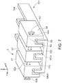
- FIG. 7 is a perspective view of a contactless power feeding apparatus in accordance with a second embodiment.
- FIG. 8 is a perspective view of a contactless power feeding apparatus in accordance with a third embodiment.
- FIG. 9 is a perspective view of a contactless power feeding apparatus in accordance with a fourth embodiment.
- FIGS. 10A and 10B are views of a conventional contactless power feeding apparatus, FIG. 10A is a perspective view, and FIG. 10B is a schematic sectional view.
- FIG. 1 is a perspective view of a contactless power feeding apparatus in accordance with a first embodiment
- FIG. 2 is a front view of the contactless power feeding apparatus in accordance with the first embodiment
- FIG. 3 is a perspective view illustrating a state where a trolley and a rail in the contactless power feeding apparatus in accordance with the first embodiment are separated from each other
- FIG. 4 is a partial exploded view of the trolley of the contactless power feeding apparatus according to the first embodiment
- FIG. 5 is a view illustrating an assembly process of the trolley of the contactless power feeding apparatus in accordance with the first embodiment
- FIG. 6 is a view illustrating the relation between the capacitance and the electrode interval of the contactless power feeding apparatus in accordance with the first embodiment.
- reference numeral 1 denotes a trolley that is a movable electrode device in the present embodiment. As illustrated in FIGS. 1 and 2 , the trolley is slidably combined with a rail 101 , which is a fixed electrode device in this embodiment, while maintaining a non-contact state with the rail 101 , to transmit electric power between the trolley 1 and the rail 101 .
- the trolley 1 and the rail 101 constitute the contactless power feeding apparatus of the present embodiment.
- the contactless power feeding apparatus can be used to form a power line for connecting a power source to power-consuming equipment in various equipment such as industrial equipment, transport equipment, and home appliances, and specifically, an alternating current (AC current) is fed in the non-contact manner through electric field coupling.
- AC current alternating current
- any of the trolley 1 and the rail 101 may be connected to the power source, and any of the trolley 1 and the rail 101 may be connected to the power-consuming equipment.
- the trolley 1 is connected to the power-consuming equipment and the rail 101 is connected to the power source, that is, the trolley 1 is on the power consumption side and the rail 101 is on the power source side.
- the rail 101 is an oblong member linearly extending in the longitudinal direction (X-axis direction), and is fixed to a main body of various equipment such as industrial equipment, transport equipment, and home appliances. Further, it is assumed that the rail is electrically connected to the power source through a conductive line, which is not illustrated.
- the rail 101 is not specifically limited, but is a long member. For convenience of illustration, however, in the example illustrated in FIGS. 1 and 2 , the dimension in the longitudinal direction is relatively short.
- the rail 101 includes an oblong band-like substrate 152 linearly extending in the longitudinal direction (X-axis direction), and guide plates 154 that are oblong band-like fixed electrode plates extending perpendicularly upward (positive Z-axis direction) from an upper face 152 a of the substrate 152 and extending linearly in the longitudinal direction.
- the substrate 152 and the guide plates 154 are, for example, members made of a conductive metal such as an aluminum alloy, but may be made of any type of conductive material.
- the number of the guide plates 154 may be any number, and for example, may be one, two, or four or more. Here, for convenience, the number of the guide plates 154 is three as illustrated in FIGS. 1 and 2 .
- All of the guide plates 154 are configured to be mutually conductive. Further, the substrate 152 and the guide plates 154 are separately-manufactured members, and may be interconnected physically and electrically using connecting members such as bolts. Here, as illustrated in FIGS. 1 and 2 , they are integrated into a single member.
- the guide plates 154 When viewed from the front or back (viewed in the X-axis longitudinal direction), the guide plates 154 are disposed in a comb-like manner, and linearly extend upward from the upper face 152 a of the substrate 152 , parallel to each other. When viewed from above or below (viewed in the Z-axis longitudinal direction), the guide plates 154 linearly extend in the longitudinal direction (X-axis direction), parallel to each other. Accordingly, upper faces 154 a of the respective guide plates 154 are parallel to the upper face 152 a of the substrate 152 , and are flush with each other. Side faces 154 b of the respective guide plates 154 are flat faces that are perpendicular to the upper face 152 a of the substrate 152 , and are parallel to each other. Further, the guide plates 154 have the same outer shape and dimensions (height, width, and length). Guide grooves 153 each formed between the adjacent guide plates 154 have the same outer shape and dimensions (height, width, and length).
- a coating film made of an insulating material (dielectric) is formed on each of the faces of the parts of the rail 101 , which are opposed to the respective parts of the trolley 1 , that is, at least the upper face 152 a of the substrate 152 as well as the upper faces 154 a and the side faces 154 b of the guide plates 154 on the surface of the rail 101 .
- the coating film is preferably a coating film made of anodized aluminum.
- the trolley 1 is a member that is slidable along the rail 101 in a state of being combined with the rail 101 .
- the trolley 1 is assumed to be fixed to a sliding member (not illustrated) that is slidable on the main body.
- the trolley 1 can slide in the longitudinal direction (X-axis direction) of the rail 101 in the state of being combined with the rail 101 , which is fixed to the main body.
- the trolley is assumed to be electrically connected to power-consuming equipment such as a motor and lighting through a conductive line not illustrated.
- the trolley 1 includes a plurality of movable electrode units 51 .
- the movable electrode units 51 correspond to the respective guide plates 154 of the rail 101 , and transmit electric power to the respective guide plates 154 by electric field coupling.
- the number of the movable electrode units 51 included in the trolley 1 may be any number such as one, two, or four or more.
- the number of the movable electrode units 51 is three, which corresponds to the number of the guide plates 154 illustrated in FIGS. 1 and 2 .
- the movable electrode units 51 are interconnected physically and electrically using a long rivet 62 that is a unit connecting member made of a conductive metal.
- the movable electrode units 51 are interconnected with a small gap 57 therebetween so as to be movable in the plate thickness direction of the guide plates 154 , that is, the lateral direction (Y-axis direction) in a floating state.
- the movable electrode units 51 each include a spacer member 52 and plate-like sliding plates 54 , which are a pair of movable electrode plates disposed on both sides of the spacer member 52 in the lateral direction.
- the spacer member 52 and the sliding plates 54 are members made of a conductive metal such as aluminum alloy, but may be made of any type of conductive material.
- the pair of sliding plates 54 are mutually conducting via the spacer member 52 .
- the spacer member 52 is connected to the pair of sliding plates 54 physically and electrically using short rivets 61 that are sliding-plate connecting members made of a conductive metal.
- the spacer member 52 and the pair of sliding plates 54 are physically and firmly interconnected so as to be unmovable with respect to each other.
- the spacer member 52 is provided with one long-rivet through hole 52 e and two short-rivet through holes 52 d, which penetrate the spacer member 52 in the thickness direction, that is, the lateral direction.
- Each of the sliding plates 54 is provided with one long-rivet through hole 54 e and two short-rivet through holes 54 d, which penetrate the sliding plate 54 in the thickness direction, that is, the lateral direction.
- the long-rivet through hole 52 e and the short-rivet through holes 52 d of the spacer member 52 are formed at positions that correspond mutually with the long-rivet through hole 54 e and the short-rivet through holes 54 d of the sliding plate 54 .
- inner side faces 54 b 1 of the sliding plates 54 are brought into contact with side faces 54 b on the both sides of the spacer member 52 in the lateral direction, the short-rivet through holes 52 d of the spacer member 52 are aligned with the short-rivet through holes 54 d of the sliding plates 54 , and shaft members 61 a of the short rivets 61 are inserted into the respective short-rivet through holes 52 d of the spacer member 52 and the respective short-rivet through holes 54 d of the sliding plates 54 .
- ends of the shaft members 61 a of the short rivets 61 each may be plastically deformed to form a head portion 61 b having a larger diameter than that of the shaft member 61 a, thereby fastening the spacer member 52 to the pair of sliding plates 54 .
- the head portions 61 b may be replaced with nuts. Besides nuts, any means capable of preventing the shaft members 61 a from escaping may be used. Through this, a movable electrode unit 51 in which the spacer member 52 is reliably connected to the pair of sliding plates 54 physically and electrically can be obtained.
- each of the movable electrode units 51 When viewed from the front or back (viewed in the X-axis longitudinal direction), each of the movable electrode units 51 is gate-shaped or U-shaped, and the pair of sliding plates 54 extends linearly downward (Z-axis negative direction) from respective both lateral ends of a lower face 52 a of the spacer member 52 to be parallel to each other.
- the sliding plates 54 When viewed from above or below (viewed in the Z-axis longitudinal direction), the sliding plates 54 linearly extend in the longitudinal direction (X-axis direction) to be parallel to each other. Accordingly, the lower face 54 a of each sliding plate 54 is parallel to the lower face 52 a of the spacer member 52 .
- each sliding plate 54 is flush with an upper face 52 c of the spacer member 52 , but may not be flush with the upper face 52 c.
- the inner side faces 54 b 1 of the sliding plates 54 are flat faces that are perpendicular to the lower face 52 a of the spacer member 52 and are parallel to each other.
- an outer side face 54 b 2 of each sliding plate 54 is desirably parallel to the inner side face 54 b 1 .
- the inner side face 54 b 1 and the outer side face 54 b 2 of the sliding plate 54 may be collectively described as the side faces 54 b of the sliding plate 54 .
- the sliding plates 54 have substantially the same outer shape and dimensions (height, width, and length).
- a sliding groove 53 is formed between the opposed sliding plates 54 .
- the outer shape and dimensions (height, width, and length) of each part of each movable electrode unit 51 are substantially the same.
- the plurality of (three in the illustrated example) movable electrode units 51 are disposed in parallel, the long-rivet through holes 52 e of the movable electrode units 51 are aligned with each other, and a shaft member 62 a of the long rivet 62 is inserted into the long-rivet through holes 54 e of all of the movable electrode units 51 .
- the shaft member 62 a is loosely fitted (movably fitted) into the long-rivet through holes 54 e.
- an end of the shaft member 62 a of the long rivet 62 is plastically deformed to form a head portion 62 b having a larger diameter than that of the shaft member 62 a, thereby coupling all of the movable electrode units 51 together.
- the head portion 62 b may be replaced with a nut. Besides the nut, any means capable of preventing the movable electrode units 51 from escaping may be used. Accordingly, all of the movable electrode units 51 can slide together in the longitudinal direction of the rail 101 .
- the small gap 57 is present between the adjacent movable electrode units 51 , and thus the movable electrode units 51 are loosely coupled to one another while being loosely fitted to the long rivet 62 so as to be independently movable in the lateral direction. Through this, the trolley 1 can be obtained.
- the movable electrode units 51 may be connected to respective ends of three conductive lines having the other ends connected to power-consuming equipment, or any one of the movable electrode units 51 may be connected to one end of one conductive line that has the other end connected to power-consuming equipment.
- each of the movable electrode units 51 is preferably connected to a respective end of the three conductive lines having the other ends connected to power-consuming equipment.
- each of the movable electrode units 51 of the trolley 1 straddles the corresponding guide plates 154 of the rail 101 , and the corresponding guide plates 154 enter the sliding grooves 53 of the movable electrode unit 51 in the non-contact state.
- the sliding plates 54 of the corresponding movable electrode units 51 enter into each guide groove 153 of the rail 101 in the non-contact state.
- a gap is present between the inner side face 54 b 1 of the sliding plate 54 and the side face 154 b of the guide plate 154 , which are opposed to each other, a gap is present between the lower face 52 a of the spacer member 52 and the upper face 154 a of the guide plate 154 , which are opposed to each other, and a gap is present between the lower face 54 a of the sliding plate 54 and the upper face 152 a of the substrate 152 , which are opposed to each other.
- the surfaces of the parts of each movable electrode unit 51 may be coated with a coating film made of an insulating material (dielectric).
- the side face 154 b of the guide plate 154 and the inner side face 54 b 1 of the sliding plate 54 are opposed to each other with a large surface area of the opposing faces and therefore, function as main electrode faces. More specifically, when viewed in the lateral direction (Y-axis longitudinal direction), overlapping portions of the side face 154 b of the guide plate 154 and the inner side face 54 b 1 of the sliding plate 54 on each side of the guide plate 154 function as electrode faces by electric field coupling.
- the mutually opposed faces of the parts of the rail 101 and the parts of the trolley 1 can also function as electrode faces by electric field coupling, but have a smaller area and are less functional as the electrode faces than the opposed faces of the side face 154 b of the guide plate 154 and the inner side face 54 b 1 of the sliding plate 54 .
- electrode faces by electric field coupling, but have a smaller area and are less functional as the electrode faces than the opposed faces of the side face 154 b of the guide plate 154 and the inner side face 54 b 1 of the sliding plate 54 .
- ⁇ denotes permittivity of the electrode gap
- S denotes the electrode area
- the relation between the capacitance C and the electrode gap d changes as indicated by a line A in FIG. 6 .
- the electrode gap d since the capacitance C lowers as the electrode gap d increases, in order to cause the side face 154 b of the guide plate 154 and the inner side face 54 b 1 of the sliding plate 54 opposed to the side face 154 b to efficiently function as the electrode faces, the electrode gap d must be maintained at a small value.
- the value of the electrode gap d is preferably 10 [ ⁇ m] or less, and more preferably 5 [ ⁇ m] or less.
- each movable electrode unit 51 straddles the guide plate 154 such that the inner side face 54 b 1 of each of the sliding plates 54 is opposed to each of the side faces 154 b of the guide plate 154 on both sides in the lateral direction. Accordingly, when the electrode gap d between one side face 154 b of the guide plate 154 and the inner side face 54 b 1 of the sliding plate 54 , which are opposed to each other, changes in the plate thickness direction of the guide plates 154 , the electrode gap d between the other side face 154 b of the guide plate 154 and the inner side face 54 b 1 of the sliding plate 54 , which are opposed to each other, changes in the opposite direction.
- the capacitance C between both side faces 154 b of the guide plate 154 and the inner side faces 54 b 1 of the pair of sliding plates 54 , which are opposed to each other changes, as represented by a line B in FIG. 6 , in response to a change in the electrode gap d between one side face 154 b of the guide plate 154 and the inner side face 54 b 1 of the sliding plate 54 , which are opposed to each other.
- the capacitance C between the both side faces 154 b of the guide plate 154 and the inner side faces 54 b 1 of the pair of sliding plates 54 , which are opposed to each other, is maintained at a practical and sufficiently large value at all times without greatly decreasing.
- the value of the gap 57 between the adjacent movable electrode units 51 is desirably set to the electrode gap d or more such that each movable electrode unit 51 is freely movable in the lateral direction.
- each movable electrode unit 51 straddles the guide plate 154 , and the inner side faces 54 b 1 of the pair of sliding plates 54 are opposed to the side faces 154 b of the guide plate 154 on both sides in the lateral direction, even when each movable electrode unit 51 moves in the plate thickness direction of the guide plate 154 , that is, the lateral direction, to change the electrode gap d between one side face 154 b of the guide plate 154 and the inner side face 54 b 1 of the sliding plate 54 , which are opposed to each other, the capacitance C between the pair of movable electrode units 51 and the guide plate 154 does not greatly decreases.
- the electrode area S is doubled for case in which the sliding plate 54 is disposed on only one side face 154 b of the guide plate 154 , a sufficiently large capacitance C can be maintained at all times. Accordingly, even when each of the movable electrode units 51 is floating in a movable manner in the lateral direction, a sufficiently large capacitance C can be maintained at all times.
- the coating film made of an insulating material (dielectric) even when the movable electrode unit 51 largely moves in the lateral direction to bring the inner side face 54 b 1 of the sliding plate 54 into contact with the side face 154 b of the guide plate 154 , electric continuity between the sliding plate 54 and the guide plate 154 never occurs. Consequently, the inner side face 54 b 1 of the sliding plate 54 and the side face 154 b of the guide plate 154 still function as electrode faces through electric field coupling via the dielectric.
- each of the movable electrode units 51 is floating in a movable manner in the lateral direction, it is not necessary to strictly position each movable electrode unit 51 with respect to the rail 101 in the lateral direction. Therefore, unlike the conventional contactless power feeding apparatus described in the “Background Art” section, an expensive linear guide is unnecessary, and thus costs can be reduced.
- the rail 101 is extremely long in particular, it is actually difficult to make the side face 154 b of the guide plate 154 completely flat over the entire length. Thus, the side face 154 b of the guide plate 154 undergoes a small displacement in the lateral direction. Even in such case, each of the movable electrode units 51 is floating in a movable manner in the lateral direction, and thus can address the displacement of the side face 154 b of the guide plate 154 in the lateral direction.
- the trolley 1 slides along the rail 101 , even when the movable electrode unit 51 moves in the lateral direction to bring the inner side face 54 b 1 of the sliding plate 54 into contact with the side face 154 b of the guide plate 154 , the sliding plate 54 moves in the opposite direction due to a reaction force from the guide plates 154 . Therefore, the trolley 1 does not continue to slide while maintaining contact between the inner side face 54 b 1 of the sliding plate 54 and the side face 154 b of the guide plate 154 . That is, the inner side face 54 b 1 of the sliding plate 54 is not in sliding-contact with the side face 154 b of the guide plate 154 over a long distance. Accordingly, the coating film made of the insulating material is not worn by the sliding-contact between the inner side face 54 b 1 of the sliding plate 54 and the side face 154 b of the guide plate 154 .
- the contactless power feeding apparatus includes the rail 101 and the trolley 1 that is movable with respect to the rail 101 , and can transmit electric power between the rail 101 and the trolley 1 by electric field coupling.
- the rail 101 includes at least one guide plate 154 extending in the longitudinal direction
- the trolley 1 is movable along the guide plate 154 in the longitudinal direction and includes at least one movable electrode unit 51 that is movable in the plate thickness direction of the guide plate 154
- the movable electrode unit 51 includes the pair of sliding plates 54 opposed to both respective side faces of the guide plate 154 , and the spacer member 52 that holds the distance between the pair of sliding plates 54 constant and brings the pair of sliding plates 54 into conduction.
- At least both side faces of the guide plates 154 are coated with the coating film formed of the dielectric. Accordingly, even when the movable electrode units 51 move significantly in the lateral direction to bring the sliding plate 54 into contact with the guide plate 154 , electric continuity between the sliding plate 54 and the guide plate 154 never occurs, and thus the sliding plate 54 and the guide plates 154 can maintain function as electrodes by electric field coupling via the dielectric.
- the rail 101 includes the plurality of guide plates 154 that are disposed in parallel to each other and in parallel in the plate thickness direction of the guide plates
- the trolley 1 includes the plurality of movable electrode units 51 disposed in parallel in the plate thickness direction of the guide plates 154
- the movable electrode units 51 are independently movable in the plate thickness direction of the guide plates 154 . This can increase the area of the electrodes, making it possible to feed a larger amount of electric power.
- each of the plurality of movable electrode units 51 is movably fitted to the long rivet 62 extending in the plate thickness direction of the guide plates 154 . Therefore, the movable electrode units 51 are independently movable in the plate thickness direction of the guide plates 154 .
- FIG. 7 is a perspective view of a contactless power feeding apparatus in accordance with a second embodiment.
- a rail 101 in this embodiment is the same as the rail 101 in the first embodiment, the description thereof is omitted.
- each of the movable electrode units 51 included in the trolley 1 is configured such that the spacer member 52 and the sliding plates 54 are integrated into a single member.
- the spacer member 52 and upper portions of the sliding plates 54 on both sides of the spacer member 52 are integrated into a sliding-plate combining body 55 .
- the sliding-plate combining body 55 has a long-rivet through hole 55 e.
- the short rivet 61 , the short-rivet through holes 52 d and the long-rivet through hole 52 e of the spacer member 52 , and the short-rivet through holes 54 d and the long-rivet through hole 54 e of the sliding plate 54 are omitted.
- the plurality of (three in the illustrated example) movable electrode units 51 are disposed in parallel, the long-rivet through holes 52 e of the movable electrode units 51 are aligned with one another, and the shaft member 62 a of the long rivet 62 is inserted into the long-rivet through holes 55 e of all of the movable electrode units 51 . Then, the end of the shaft member 62 a of the long rivet 62 is plastically deformed to form the head portion 62 b having a larger diameter than that of the shaft member 62 a, thereby coupling all of the movable electrode units 51 together. Accordingly, all of the movable electrode units 51 are slidable in the longitudinal direction of the rail 101 . At this time, the gap 57 is present between the adjacent movable electrode units 51 , and all of the movable electrode units 51 are loosely coupled together so as to be independently movable in the lateral direction. Through this, the trolley 1 can be obtained.
- the spacer member 52 and the pair of sliding plates 54 are integrated into a single member. Accordingly, the movable electrode units 51 can be easily manufactured with a high level of precision.
- FIG. 8 is a perspective view of a contactless feeding apparatus in accordance with a third embodiment.
- a rail 101 in this embodiment is the same as the rail in the first and second embodiments, the description thereof is omitted.
- each movable electrode unit 51 in the trolley 1 in this embodiment is the same as the movable electrode unit 51 in the second embodiment, a description thereof is omitted.
- an elastic conductive member 63 which is an electric unit connecting member for bringing adjacent movable electrode units 51 into conduction, is attached to the long rivet 62 , which is the unit connecting member for connecting the movable electrode units 51 to one another.
- the elastic conductive member 63 is attached around the portion of the shaft member 62 a of the long rivet 62 , which is exposed between the adjacent movable electrode units 51 , and both ends of the elastic conductive member 63 in the lateral direction (Y-axis direction) are in contact with respective side faces of the sliding-plate combining bodies 55 of the movable electrode units 51 which are located on both sides of the elastic conductive member.
- the elastic conductive member 63 may be made of any type of conductive material that can expand and contract in the lateral direction (Y-axis direction), including for example, foam metal, metallic coil spring, metallic mesh, and conductive rubber.
- the elastic conductive member 63 may be formed by inserting the shaft member 62 a into a through hole of a previously-produced tubular member, or by wrapping a long flexible plate-like member around the shaft member 62 a.
- the elastic conductive member 63 which can expand and contract in the plate thickness direction of the guide plates 154 and bring the adjacent movable electrode units 51 into conduction, is disposed between the adjacent movable electrode units 51 . Therefore, even when each of the movable electrode units 51 moves in the lateral direction, electric continuity between the adjacent movable electrode units 51 can be reliably maintained
- FIG. 9 is a perspective view of a contactless power feeding apparatus in accordance with a fourth embodiment.
- a rail 101 in this embodiment is the same as the rail 101 in the first to third embodiments, a description thereof is omitted.
- the spacer member 52 and the upper portions of the sliding plates 54 on both sides of the spacer member 52 are integrated into the sliding-plate combining body 55 , but unlike the second and third embodiments, the movable electrode units 51 are connected to one another using a connecting block 11 in place of the long rivet 62 . That is, in this embodiment, the connecting block 11 is used as the unit connecting member rather than the long rivet 62 .
- the connecting block 11 includes a rectangular flat plate-like top plate 14 extending in the longitudinal direction (X-axis direction) and the lateral direction (Y-axis direction), and a plurality of band plate-like unit holding plates 13 that perpendicularly extend from the lower face of the top plate 14 downward (Z-axis negative direction) and linearly extend in the longitudinal direction.
- the unit holding plates 13 are members for holding the sliding-plate combining body 55 of each movable electrode unit 51 from both sides, and a plurality of unit holding plates 13 (four in the illustrated view) is disposed with a quantity that is one more than the number of movable electrode units 51 (three in the illustrated example).
- a holding projection 13 a protrudes from the lower end of the unit holding plate 13 in the lateral direction.
- the holding projection 13 a protrudes from the lower end of the unit holding plate 13 located between adjacent movable electrode units 51 to both sides in the lateral direction, and protrudes from the lower ends of the unit holding plates 13 extending from both ends of the top plate 14 in the lateral direction to only one side in the lateral direction.
- a holding groove 12 extending in the longitudinal direction is formed between the adjacent unit holding plates 13 .
- Upper portions of the holding projections 13 a on both sides in the lateral direction in the holding groove 12 constitute holding recesses 12 a.
- the connecting block 11 is preferably an integral member made of a conductive material such as metal.
- groove-like held recesses 58 extending in the longitudinal direction are formed on both side faces of the sliding-plate combining body 55 of the movable electrode unit 51 .
- Upper portions of the held recesses 58 on the both side faces of the sliding-plate combining body 55 in the lateral direction constitute held projections 59 .
- Each movable electrode unit 51 is held by the connecting block 11 by inserting the sliding-plate combining body 55 into the corresponding holding groove 12 .
- the held projections 59 of the sliding-plate combining body 55 enter into the holding recesses 12 a of the holding groove 12
- the holding projections 13 a of the unit holding plates 13 enter into the held recesses 58 of the sliding-plate combining body 55 . Since the dimensions of each portion of the holding groove 12 in the lateral direction are set to be larger than the dimensions of the corresponding portion of the sliding-plate combining body 55 in the lateral direction, and preferably, the electrode gap d, each movable electrode unit 51 is loosely fitted into the holding groove 12 and is freely movable in the lateral direction.
- the sliding-plate combining body 55 is stored in the corresponding holding groove 12 and then, downwardly-extending stoppers 15 are attached to front and rear end faces of the top plate 14 at positions corresponding to the holding grooves 12 .
- the portions in the vicinity of the lower ends of the stoppers 15 engage with the front and rear end faces of the sliding-plate combining body 55 , thereby preventing the sliding-plate combining body 55 from escaping from the holding groove 12 .
- the trolley 1 can be obtained.
- the trolley 1 includes the connecting block 11 in which the plurality of holding grooves 12 disposed in parallel in the plate thickness direction of the guide plate 154 are formed, and each of the plurality of movable electrode units 51 is movably fitted into the respective holding groove 12 and held. Accordingly, the trolley 1 can be easily produced with high precision.
Landscapes
- Engineering & Computer Science (AREA)
- Computer Networks & Wireless Communication (AREA)
- Power Engineering (AREA)
- Manufacturing & Machinery (AREA)
- Microelectronics & Electronic Packaging (AREA)
- Current-Collector Devices For Electrically Propelled Vehicles (AREA)
Abstract
Description
C=ε(S/d). Equation (1)
Claims (7)
Applications Claiming Priority (2)
| Application Number | Priority Date | Filing Date | Title |
|---|---|---|---|
| JP2018041812A JP2019161726A (en) | 2018-03-08 | 2018-03-08 | Non-contact power supply device |
| JP2018-041812 | 2018-03-08 |
Publications (2)
| Publication Number | Publication Date |
|---|---|
| US20190280525A1 US20190280525A1 (en) | 2019-09-12 |
| US10797519B2 true US10797519B2 (en) | 2020-10-06 |
Family
ID=67843539
Family Applications (1)
| Application Number | Title | Priority Date | Filing Date |
|---|---|---|---|
| US16/292,360 Expired - Fee Related US10797519B2 (en) | 2018-03-08 | 2019-03-05 | Contactless power feeding apparatus |
Country Status (3)
| Country | Link |
|---|---|
| US (1) | US10797519B2 (en) |
| JP (1) | JP2019161726A (en) |
| CN (1) | CN110247481B (en) |
Families Citing this family (2)
| Publication number | Priority date | Publication date | Assignee | Title |
|---|---|---|---|---|
| JP2019207829A (en) | 2018-05-30 | 2019-12-05 | モレックス エルエルシー | socket |
| JP7358296B2 (en) * | 2020-05-19 | 2023-10-10 | 新光電気工業株式会社 | Contactless power supply device |
Citations (8)
| Publication number | Priority date | Publication date | Assignee | Title |
|---|---|---|---|---|
| US20020132589A1 (en) * | 2001-03-16 | 2002-09-19 | Tamagawa Seiki Kabushiki Kaisha | Rotary non-contact connector and non-rotary non-contact connector |
| US20060279831A1 (en) * | 2005-06-09 | 2006-12-14 | Mckinnell James | Micro-electro mechanical light modulator device |
| JP2015099880A (en) | 2013-11-20 | 2015-05-28 | 三星テクウィン株式会社Samsung Techwin Co., Ltd | Work machine |
| US20150228403A1 (en) * | 2012-07-17 | 2015-08-13 | Stichting National Lucht-En Ruimtevaart Laboratorium | Contactless power and data transfer |
| JP5980329B2 (en) | 2012-07-02 | 2016-08-31 | 富士機械製造株式会社 | Electrostatic coupling type non-contact power feeding device |
| JP6170055B2 (en) | 2012-09-20 | 2017-07-26 | 富士機械製造株式会社 | Non-contact power feeding device |
| US20170278646A1 (en) * | 2014-09-26 | 2017-09-28 | Sony Corporation | Switching apparatus and electronic apparatus |
| US20190252916A1 (en) * | 2018-02-15 | 2019-08-15 | Velodyne Lidar, Inc. | Systems and methods for transmitting data via a contactless cylindrical interface |
Family Cites Families (4)
| Publication number | Priority date | Publication date | Assignee | Title |
|---|---|---|---|---|
| JP2011259649A (en) * | 2010-06-11 | 2011-12-22 | Takenaka Komuten Co Ltd | Electrode structure for non-contact power supply system, and non-contact power supply system |
| JP2014524726A (en) * | 2011-08-16 | 2014-09-22 | コーニンクレッカ フィリップス エヌ ヴェ | A technique for efficient power transfer in capacitive wireless power transfer systems |
| JP6104231B2 (en) * | 2012-03-28 | 2017-03-29 | 富士機械製造株式会社 | Electrostatic coupling type non-contact power feeding device |
| CN104472030B (en) * | 2012-07-12 | 2018-02-06 | 富士机械制造株式会社 | Contactless power supply device |
-
2018
- 2018-03-08 JP JP2018041812A patent/JP2019161726A/en active Pending
-
2019
- 2019-03-05 US US16/292,360 patent/US10797519B2/en not_active Expired - Fee Related
- 2019-03-07 CN CN201910172395.6A patent/CN110247481B/en not_active Expired - Fee Related
Patent Citations (8)
| Publication number | Priority date | Publication date | Assignee | Title |
|---|---|---|---|---|
| US20020132589A1 (en) * | 2001-03-16 | 2002-09-19 | Tamagawa Seiki Kabushiki Kaisha | Rotary non-contact connector and non-rotary non-contact connector |
| US20060279831A1 (en) * | 2005-06-09 | 2006-12-14 | Mckinnell James | Micro-electro mechanical light modulator device |
| JP5980329B2 (en) | 2012-07-02 | 2016-08-31 | 富士機械製造株式会社 | Electrostatic coupling type non-contact power feeding device |
| US20150228403A1 (en) * | 2012-07-17 | 2015-08-13 | Stichting National Lucht-En Ruimtevaart Laboratorium | Contactless power and data transfer |
| JP6170055B2 (en) | 2012-09-20 | 2017-07-26 | 富士機械製造株式会社 | Non-contact power feeding device |
| JP2015099880A (en) | 2013-11-20 | 2015-05-28 | 三星テクウィン株式会社Samsung Techwin Co., Ltd | Work machine |
| US20170278646A1 (en) * | 2014-09-26 | 2017-09-28 | Sony Corporation | Switching apparatus and electronic apparatus |
| US20190252916A1 (en) * | 2018-02-15 | 2019-08-15 | Velodyne Lidar, Inc. | Systems and methods for transmitting data via a contactless cylindrical interface |
Also Published As
| Publication number | Publication date |
|---|---|
| JP2019161726A (en) | 2019-09-19 |
| US20190280525A1 (en) | 2019-09-12 |
| CN110247481A (en) | 2019-09-17 |
| CN110247481B (en) | 2022-10-18 |
Similar Documents
| Publication | Publication Date | Title |
|---|---|---|
| EP3156805B1 (en) | Probe pin and electronic device using same | |
| CN111602062B (en) | Probe, inspection tool, inspection unit, and inspection apparatus | |
| EP2871694B1 (en) | Battery cell and battery module using same | |
| US10797519B2 (en) | Contactless power feeding apparatus | |
| US20150036272A1 (en) | Electronic device and substrate unit | |
| US20130107436A1 (en) | Power supply unit and power supply system for servers | |
| JP2017147196A (en) | Power storage device | |
| CN106328878A (en) | Double-headed connecting device for electric automobile battery module | |
| US20160233601A1 (en) | Header, receptacle, connector, and method of manufacturing the header | |
| US7982368B2 (en) | Polymer actuator and device equipped with polymer actuator | |
| US20140329398A1 (en) | Contact, connector, and connecting device | |
| US20240243375A1 (en) | Voltage acquisition structure, and battery module having voltage acquisition structure | |
| CN111579834B (en) | Probe and connector suitable for high-current high-speed signal test | |
| KR20110059386A (en) | Cell Voltage Monitoring Terminal for Fuel Cell Stack | |
| CN218997142U (en) | Spring type probe | |
| US11108110B2 (en) | Battery holder and side frame thereof | |
| KR101306516B1 (en) | Wiring duct connection device | |
| JP2018056244A (en) | Pressure welding unit and power semiconductor device | |
| CN205248741U (en) | Bus -bar system coupler | |
| KR101569777B1 (en) | Multi-contact connector having electrical contact and this piece, plug, socket | |
| CN111579831A (en) | Probe and connector suitable for high-current high-speed signal test | |
| US11209461B2 (en) | Probe card device and neck-like probe thereof | |
| CN223756850U (en) | High-voltage-resistant test insulation mechanism | |
| CN212364374U (en) | Probe and connector suitable for high-current high-speed signal test | |
| CN210120048U (en) | An on-load tap-changer adjusting capacity contact device |
Legal Events
| Date | Code | Title | Description |
|---|---|---|---|
| FEPP | Fee payment procedure |
Free format text: ENTITY STATUS SET TO UNDISCOUNTED (ORIGINAL EVENT CODE: BIG.); ENTITY STATUS OF PATENT OWNER: LARGE ENTITY |
|
| AS | Assignment |
Owner name: MOLEX LLC, ILLINOIS Free format text: ASSIGNMENT OF ASSIGNORS INTEREST;ASSIGNOR:NIITSU, TOSHIHIRO;REEL/FRAME:049107/0684 Effective date: 20190507 |
|
| STPP | Information on status: patent application and granting procedure in general |
Free format text: NOTICE OF ALLOWANCE MAILED -- APPLICATION RECEIVED IN OFFICE OF PUBLICATIONS |
|
| STPP | Information on status: patent application and granting procedure in general |
Free format text: PUBLICATIONS -- ISSUE FEE PAYMENT VERIFIED |
|
| STCF | Information on status: patent grant |
Free format text: PATENTED CASE |
|
| FEPP | Fee payment procedure |
Free format text: MAINTENANCE FEE REMINDER MAILED (ORIGINAL EVENT CODE: REM.); ENTITY STATUS OF PATENT OWNER: LARGE ENTITY |
|
| LAPS | Lapse for failure to pay maintenance fees |
Free format text: PATENT EXPIRED FOR FAILURE TO PAY MAINTENANCE FEES (ORIGINAL EVENT CODE: EXP.); ENTITY STATUS OF PATENT OWNER: LARGE ENTITY |
|
| STCH | Information on status: patent discontinuation |
Free format text: PATENT EXPIRED DUE TO NONPAYMENT OF MAINTENANCE FEES UNDER 37 CFR 1.362 |
|
| FP | Lapsed due to failure to pay maintenance fee |
Effective date: 20241006 |